HLMP-C415-X0001中文资料
大庆451轮设备明细表

大庆451轮船舶设备明细表(大连造船厂、船号PC460 —1 )出厂日期:大庆451轮船舶设备明细表(大连造船厂、船号PC460 —1 )出厂日期:大庆451轮船舶设备明细表(大连造船厂、船号PC460 —1 )出厂日期:大庆451轮船舶设备明细表(大连造船厂、船号PC460 —1 )出厂日期:大庆451轮船舶设备明细表(大连造船厂、船号PC460 —1 )出厂日期:大庆451轮船舶设备明细表(大连造船厂、船号PC460 —1 )出厂日期:大庆451轮船舶设备明细表(大连造船厂、船号PC460 —1 )出厂日期:大庆451轮船舶设备明细表(大连造船厂、船号PC460 —1 )出厂日期:大庆451轮船舶设备明细表(大连造船厂、船号PC460 —1 )出厂日期:大庆451轮船舶设备明细表(大连造船厂、船号PC460 —1 )出厂日期:大庆451轮船舶设备明细表(大连造船厂、船号PC460 —1 )出厂日期:大庆451轮船舶设备明细表(大连造船厂、船号PC460 —1 )出厂日期:大庆451轮船舶设备明细表(大连造船厂、船号PC460 —1 )出厂日期:大庆451轮船舶设备明细表(大连造船厂、船号PC460 —1 )出厂日期:大庆451轮船舶设备明细表(大连造船厂、船号PC460 —1 )出厂日期:大庆451轮船舶设备明细表(大连造船厂、船号PC460 —1 )出厂日期:大庆451轮船舶设备明细表(大连造船厂、船号PC460 —1 )出厂日期:大庆451轮船舶设备明细表(大连造船厂、船号PC460 —1 )出厂日期:大庆451轮船舶设备明细表(大连造船厂、船号PC460 —1 )出厂日期:大庆451轮船舶设备明细表(大连造船厂、船号PC460 —1 )出厂日期:大庆451轮船舶设备明细表(大连造船厂、船号PC460 —1 )出厂日期:大庆451轮船舶设备明细表(大连造船厂、船号PC460 —1 )出厂日期:大庆451轮船舶设备明细表(大连造船厂、船号PC460 —1 )出厂日期:大庆451轮船舶设备明细表(大连造船厂、船号PC460 —1 ) 出厂日期:大庆451轮船舶设备明细表(大连造船厂、船号PC460 —1 )出厂日期:大庆451轮船舶设备明细表(大连造船厂、船号PC460 —1 )出厂日期:。
1秦皇岛市雷射电子科技有限公司

10400 12688
5350 4550
昭阳 E42G T5750 (DC12.0G-667)
T5750 (DC2.0G- 667) “酷睿 ”2双核 64 位笔记本电脑专用 CPU/14.1 ’ WXGA TFT 防眩光雾面宽屏液晶显示屏 /1G
(1*1G DDRII 667 )/ 160G HDD( 5400 转)/COMBO/56Kb Modem/WIRELESS LAN a+b+g
置 亮度 3500 流明 /分辨率 1024*768/ 对比度 500 : 1/支持 S 端子 /支持 VGA 端口 /支持 RGB 端口 /标准配置 亮度 2700 流明 /分辨率 1024*768/ 对比度 400 : 1/支持 S 端子 /支持 VGA 端口 /支持 RGB 端口 /标准配置 亮度 2700 流明 /分辨率 1024*768/ 对比度 400 : 1/支持 S 端子 /支持 VGA 端口 /支持 RGB 端口 /标准配置 亮度 2000 流明 /分辨率 800*600/ 对比度 500 : 1/支持 S 端子 /支持 VGA 端口 /支持 RGB 端口 /标准配置
标准服务
昭阳 E42G T5450 (DC1.6G- 667) “酷睿 ”2双核 64 位笔记本电脑专用 CPU/14.1’ WXGA TFT 防眩光雾面宽屏液晶显
示屏 /512M DDRII 667/ 160G HDD ( 5400 转) /COMBO/56Kb Modem/WIRELESS LAN a+b+g 无线局域网卡
2
文档来源为 :从网络收集整理 .word 版本可编辑 .欢迎下载支持 .
25
东芝
26
东芝
笔记本报价
CSNE151中文资料
CSNE151中⽂资料Representative photograph, actual product appearance may vary.Due to regional agency approval requirements, some products may not be available in your area. Please contact your regional Honeywell office regarding your product of choice. CSNE151CSN Series closed loop current sensor, measures AC, DC or impulse current, 25 amp-turns nominal, ± 36 amp-turns range, smaller housing, 1000 turnFeaturesCurrent sensing up to 1200 ampsMeasures ac, dc and impulse currentsCompetitive cost/performance ratioRapid responseHigh overload capabilityHigh level of electrical isolation between primary and secondary circuitsIndustrial operating temperature rangeSmall size and weightTypical ApplicationsVariable speed drivesOvercurrent protectionGround fault detectorsCurrent feedback control systemsRoboticsUPS and telecommunication power suppliesWelding power suppliesAutomotive - Battery management systemsWattmetersDescriptionThe CSN Series of closed loop current sensors are based on the principles of the Magnetoresistive or Hall effects, and the null balance or zero magnetic flux method (feedback system). The magnetic flux in the sensor core is constantly controlled at zero. The amount of current required to balance zero flux is the measure of the primary current flowing through the conductor, multiplied by the ratio of the primary to secondary windings. This closed loop current is the output from the device and presents an image of the primary current reduced by thenumber of secondary turns at any time. This current can be expressed as a voltage by passing it through a resistor.CSNE151CSN Series closed loop current sensor, measures AC, DC or impulse current, 25 amp-turns nominal, ± 36 amp-turns range, smaller housing, 1000 turnProduct SpecificationsSensor Type Closed Loop LinearSensed Current Type ac or dcSensed Current Range± 36 APackage Style Series Connect PCB MountOutput Type CurrentMaximum Continuous Current± 36 ASupply Current± 10 mA + outputSupply Voltage± 15.0 VdcOffset Current< ± 0.15 mAOffset Current Drift< ± 0.6 mACoil Resistance @ 70 °C110 OhmResponse Time< 1 µsCoil Turns1000Output Nominal25 mAOperating Temperature Range0 °C to 70 °C [32 °F to 158 °F]Storage Temperature Range-40 °C to 90 °C [-40 °F to 194 °F]Minimum Measuring Resistance100 OhmMaximum Measuring Resistance320 OhmHousing Material Glass-filled PBT (UL94-V0)Mounting PCB on 13 pinsPinout Style 5 pinAccuracy± 0.5 %Availability GlobalComment Standard 25 A sensor with 5 integral primary turns. UNSPSC Code411121UNSPSC Commodity411121 TransducersSeries Name CSN SeriesCSNE151CSN Series closed loop current sensor, measures AC, DC or impulse current, 25 amp-turns nominal, ± 36 amp-turns range, smaller housing, 1000 turnCSNE151CSN Series closed loop current sensor, measures AC, DC or impulse current, 25 amp-turns nominal, ± 36 amp-turns range, smaller housing, 1000 turn PERSONAL INJURYDO NOT USE these products as safety or emergency stop devices, or in any other application where failure of the product could result in personal injury.Failure to comply with these instructions could result in death or serious injury.MISUSE OF DOCUMENTATIONThe information presented in this product sheet (or catalog) is for reference only.DO NOT USE this document as product installation information.Complete installation, operation and maintenance information is provided in the instructions supplied with each product. Failure to comply with these instructions could result in death or serious injury.Copyright Honeywell Inc.1998-2006 All rights reserved.。
东方红1504拖拉机参数对比
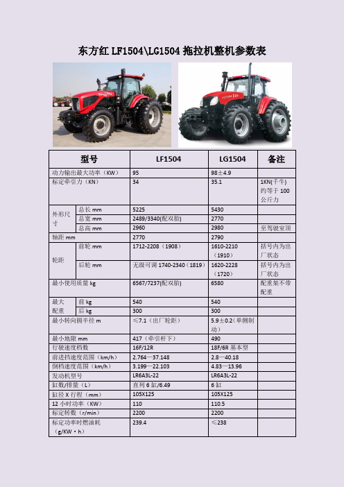
东方红LF1504\LG1504拖拉机整机参数表型号LF1504 LG1504备注动力输出最大功率(KW ) 95 98±4.9标定牵引力(KN )3435.11KN(千牛)约等于100公斤力 外形尺寸 总长mm 52255430 总宽mm 2489/3340(配双胎) 2770总高mm 2960 2980 至驾驶室顶 轴距mm27702790轮距前轮mm1712-2208(1908)1610-2210(1910)括号内为出厂状态 后轮mm无级可调1740-2340(1819) 1620-2228(1720) 括号内为出厂状态 最小使用质量kg 6567/7237(配双胎) 6580 配重架不带配重 最大 配重前kg 540 540 后kg300300最小转向圆半径m ≤7.1(出厂轮距) 5.9±0.2(单侧制动) 最小地隙mm 417(牵引杆下) 490行驶速度档数16F/12R 18F/6R 基本型 前进挡速度范围(km/h ) 2.764—37.148 2.8—40.18 倒档速度范围(km/h ) 3.199—22.103 4.83—13.96 发动机型号 LR6A3L-22 LR6A3L-22 缸数/排量(L ) 直列6缸/6.49 6缸 缸径X 行程(mm ) 105X125 105X125 12小时功率(KW ) 110 110.5 标定转数(r/min ) 2200 2200 标定功率时燃油耗(g/KW ·h )239.4≤238主离合器湿式、多片,电液操纵,电控动力换向干式、单片、全独立双作用离合器。
主离合脚踏板机械操纵,副离合器手柄机械操作后中央传动螺旋锥齿轮副螺旋锥齿轮副后差速器四个行星直齿锥齿轮,分体式差速器壳开式、四个行星直齿锥齿轮,后最终传动单级行星齿轮式单级行星齿轮式后差速锁湿式、多片,电液操纵锁销式,脚踏板机械操纵,结合状态可锁定前驱动桥中置传动轴,中央摆销中置整体式前中央传动螺旋圆锥齿轮副螺旋圆锥齿轮副前差速器限滑式限滑,闭式,四个行星直齿锥齿轮前最终传动单级行星齿轮式单级行星齿轮式分动箱湿式多片常压式离合器,弹簧压紧,电控液压分离中置式直齿圆柱齿轮,带机械操纵接合分离机构行走系机架无机架无机架轮胎规格(吋)前轮14.9—28 10PR 14.9—28后轮18.4—38 10PR 18.4—38 轮胎气压(kpa)运输时前轮200 147—196后轮200 147—196 耕地时前轮100~15098—118后轮100~15098—118 前轮定位前轮前束(mm)0~100~10前轮外倾角 1.5°1°主销内倾角7°5°30′主销后倾角6°0°前桥摆角11°每边11°每边转向系转向形式与液压提升及液压输出系统供油,全液压前轮转向;放相片角度、高度可调。
HLMP-EH15中文资料

T-13/4 (5 mm) Precision Optical Performance AlInGaP LED LampsData SheetFeatures• Well Defined Spatial Radiation Patterns• Viewing Angles: 6°, 15°, 23°, 30°• High Luminous Output• Colors:590 nm Amber605 nm Orange615 nm Reddish-Orange626 nm Red• High Operating Temperature:T J LED=+130°C• Superior Resistance to Moisture• Package Options:With or Without Lead Stand-OffsBenefits• Viewing Angles Match Traffic Management Sign Requirements• Colors Meet Automotive and Pedestrian Signal Specifications• Superior Performance in Outdoor Environments• Suitable for Autoinsertion onto PC Boards Applications• Traffic Management:Traffic SignalsPedestrian SignalsWork Zone Warning LightsVariable Message Signs• Commercial OutdoorAdvertising:SignsMarquees• Automotive:Exterior and Interior LightsDescriptionThese Precision Optical Perform-ance AlInGaP LEDs providesuperior light output for excellentreadability in sunlight and areextremely reliable. AlInGaP LEDtechnology provides extremelystable light output over longperiods of time. Precision OpticalPerformance lamps utilize thealuminum indium gallium phos-phide (AlInGaP) technology.These LED lamps are untinted,nondiffused, T-13/4 packagesincorporating second generationoptics producing well definedspatial radiation patterns atspecific viewing cone angles.SunPower SeriesHLMP-ELxxHLMP-EJxxHLMP-EHxxHLMP-EGxxThese lamps are made with anadvanced optical grade epoxy,offering superior high tempera-ture and high moisture resistanceperformance in outdoor signaland sign applications. The highmaximum LED junction tempera-ture limit of +130°C enables hightemperature operation in brightsunlight conditions. The packageepoxy contains both uv-a anduv-b inhibitors to reduce theeffects of long term exposure todirect sunlight.These lamps are available in twopackage options to give thedesigner flexibility with devicemounting.Device Selection GuideTypicalViewing Color and Luminous Angle Dominant Lamps Without Standoffs Lamps With Standoffs Intensity Iv (mcd) [1,2] 2θ1/2Wavelength on Leads on Leads@ 20 mA (Deg.)[4](nm), Typ.[3] (Outline Drawing A)(Outline Drawing B)Min.Max.HLMP-EL08-VY000HLMP-EL10-VY000360013800HLMP-EL08-VYK00*360013800HLMP-EL08-VXK00*360010700HLMP-EL08-VX400**360010700HLMP-EL08-VX000360010700HLMP-EL08-WZ000HLMP-EL10-WZ000470018400HLMP-EL08-XZ400**620018400 Amber 590HLMP-EL08-XZ000620018400HLMP-EL08-XZK00*620018400HLMP-EL08-XY000620013800HLMP-EL08-XYK00*620013800HLMP-EL08-X1K00*620024100HLMP-EL08-X1000HLMP-EL10-X1000620024100 6°[5]HLMP-EJ08-WZ000HLMP-EJ10-WZ000470018400 Orange 605HLMP-EJ08-X1000HLMP-EJ10-X1000620024100HLMP-EJ08-Y2000HLMP-EJ10-Y2000800031000HLMP-EH08-UX000HLMP-EH10-UX000275010700HLMP-EH08-VY000HLMP-EH10-VY000360013800 Red-Orange 615HLMP-EH08-WZ000HLMP-EH10-WZ000470018400HLMP-EH08-X1000HLMP-EH10-X1000620024100HLMP-EH08-Y2000HLMP-EH10-Y2000800031000HLMP-EG08-VW00036008300HLMP-EG08-VY000HLMP-EG10-VY000360013800HLMP-EG08-WZ000HLMP-EG10-WZ000470018400 Red 626HLMP-EG08-X1000HLMP-EG10-X1000620024100HLMP-EG08-YZ000800018400HLMP-EG08-Y1000800024100HLMP-EG08-Y2000HLMP-EG10-Y2000800031000 Notes:1. The luminous intensity is measured on the mechanical axis of the lamp package.2.The optical axis is closely aligned with the package mechanical axis.3. The dominant wavelength, λd, is derived from the CIE Chromaticity Diagram and represents the color of the lamp.4. θ1/2 is the off-axis angle where the luminous intensity is one half the on-axis intensity.5.The intensity of narrow viewing angle lamps is measured at the intensity peak.Part numbers in bold are recommended for new designs.*HLMP-xLxx-xxK00 are selected to amber color bins 2 and 4 only.Device Selection Guide (Continued)TypicalViewing Color and Luminous Angle Dominant Lamps Without Standoffs Lamps With Standoffs Intensity Iv (mcd) [1,2] 2θ1/2Wavelength on Leads on Leads@ 20 mA (Deg.)[4](nm), Typ.[3] (Outline Drawing A)(Outline Drawing B)Min.Max.HLMP-EL15-PS000HLMP-EL17-PS0007652900HLMP-EL15-QR00010002200HLMP-EL15-QRK00*10002200HLMP-EL15-QS00010002900 Amber 590HLMP-EL15-QS400**10002900HLMP-EL15-QSK00*10002900HLMP-EL15-QT000HLMP-EL17-QT00010003700 15°HLMP-EL15-QTK00*10003700HLMP-EL15-RU000HLMP-EL17-RU00013004800HLMP-EJ15-PS0007652900 Orange 605HLMP-EJ15-RU000HLMP-EJ17-RU00013004800HLMP-EJ15-SV000HLMP-EJ17-SV00016506300 Red-Orange 615HLMP-EH15-QT000HLMP-EH17-QT00010003700HLMP-EH15-RU000HLMP-EH17-RU00013004800HLMP-EG15-PS0007652900 Red 626HLMP-EG15-QT000HLMP-EG17-QT00010003700HLMP-EG15-RU000HLMP-EG17-RU00013004800HLMP-EL24-MQ0004501730HLMP-EL24-NR000HLMP-EL26-NR0005902200HLMP-EL24-PS000HLMP-EL26-PS0007652900HLMP-EL24-PSK00*7652900HLMP-EL24-PR400**7652200HLMP-EL24-PQK00*7651730 Amber 590HLMP-EL24-QR00010002200HLMP-EL24-QRK00*10002200 23°HLMP-EL24-QS00010002900HLMP-EL24-QSK00*10002900HLMP-EL24-QS400**10002900HLMP-EL24-QT000HLMP-EL26-QT00010003700HLMP-EL24-QTK00*10003700 Notes:1. The luminous intensity is measured on the mechanical axis of the lamp package.2.The optical axis is closely aligned with the package mechanical axis.3. The dominant wavelength, λd, is derived from the CIE Chromaticity Diagram and represents the color of the lamp.4. θ1/2 is the off-axis angle where the luminous intensity is one half the on-axis intensity.5.The intensity of narrow viewing angle lamps is measured at the intensity peak.Device Selection Guide (Continued)TypicalViewing Color and Luminous Angle Dominant Lamps Without Standoffs Lamps With Standoffs Intensity Iv (mcd) [1,2] 2θ1/2Wavelength on Leads on Leads@ 20 mA (Deg.)[4](nm), Typ.[3] (Outline Drawing A)(Outline Drawing B)Min.Max.Orange 605HLMP-EJ24-QT000HLMP-EJ26-QT00010003700HLMP-EJ24-RU000HLMP-EJ26-RU00013004800HLMP-EH26-PS0007652900 Red-Orange 615HLMP-EH24-QT000HLMP-EH26-QT00010003700 23ºHLMP-EH24-RU000HLMP-EH26-RU00013004800HLMP-EG24-PS000HLMP-EG26-PS0007652900 Red 626HLMP-EG24-QT000HLMP-EG26-QT00010003700HLMP-EG24-RU000HLMP-EG26-RU00013004800HLMP-EL30-MQ000HLMP-EL32-MQ0004501730HLMP-EL30-NR000HLMP-EL32-NR0005902200HLMP-EL30-PQ0007651730HLMP-EL30-PQK00*7651730 Amber 590HLMP-EL30-PR0007652200HLMP-EL30-PR400**7652200HLMP-EL30-PRK00*7652200HLMP-EL30-PS000HLMP-EL32-PS0007652900HLMP-EL30-PSK00*7652900 30°HLMP-EJ30-MQ0004501730 Orange 605HLMP-EJ30-NR000HLMP-EJ32-NR0005902200HLMP-EJ30-PS000HLMP-EJ32-PS0007652900HLMP-EH30-MQ000HLMP-EH32-MQ0004501730 Red-Orange 615HLMP-EH30-NR000HLMP-EH32-NR0005902200HLMP-EH30-PS000HLMP-EH32-PS0007652900HLMP-EG30-KN0002701010HLMP-EG30-MQ000HLMP-EG32-MQ0004501730HLMP-EG30-NQ0005901730HLMP-EG30-NR000HLMP-EG32-NR0005902200 Red 626HLMP-EG30-PQ0007651730HLMP-EG30-PR0007652200HLMP-EG30-PS000HLMP-EG32-PS0007652900 Notes:1. The luminous intensity is measured on the mechanical axis of the lamp package.2.The optical axis is closely aligned with the package mechanical axis.3. The dominant wavelength, λd, is derived from the CIE Chromaticity Diagram and represents the color of the lamp.4. θ1/2 is the off-axis angle where the luminous intensity is one half the on-axis intensity.5.The intensity of narrow viewing angle lamps is measured at the intensity peak.Part Numbering SystemHLMP-x x xx-x x x xxMechanical Options00: Bulk PackagingDD: Ammo PackYY: Flexi-Bin; Bulk PackagingZZ: Flexi-Bin; Ammo PackColor Bin Selections0: No color bin limitation4: Amber color bin 4 onlyK: Amber color bins 2 and 4 onlyMaximum Intensity Bin0: No Iv bin limitationMinimum Intensity BinViewing Angle & Lead Stand Offs08: 6 deg without lead stand offs10: 6 deg with lead stand offs15: 15 deg without lead stand offs17: 15 deg with lead stand offs24: 23 deg without lead stand offs26: 23 deg with lead stand offs30: 30 deg without lead stand offs32: 30 deg with lead stand offsColorG: 626 nm RedH: 615 nm Red-OrangeJ: 605 nm OrangeL: 590 nm AmberPackageE: 5 mm RoundNOTES:1. ALL DIMENSIONS ARE IN MILLIMETERS (INCHES).2. LEADS ARE MILD STEEL, SOLDER DIPPED.3. TAPERS SHOWN AT TOP OF LEADS (BOTTOM OF LAMP PACKAGE) INDICATE AN EPOXY MENISCUS THAT MAY EXTEND ABOUT 1 mm (0.040 in.) DOWN THE LEADS.4. RECOMMENDED PC BOARD HOLE DIAMETERS:• LAMP PACKAGE A WITHOUT STAND-OFFS: FLUSH MOUNTING AT BASE OF LAMP PACKAGE = 1.143/1.067 (0.044/0.042).• LAMP PACKAGE B WITH STAND-OFFS: MOUNTING AT LEAD STAND-OFFS = 0.965/0.889 (0.038/0.035).5. FOR DOME HEIGHTS ABOVE LEAD STAND-OFF SEATING PLANE, d, LAMP PACKAGE B, SEE TABLE.BPackage DimensionsA(0.039)(0.039)PART NO.d HLMP-XX1012.37 ± 0.25 (0.487 ± 0.010)HLMP-XX1712.42 ± 0.25 (0.489 ± 0.010)HLMP-XX2612.52 ± 0.25 (0.493 ± 0.010)HLMP-XX3211.96 ± 0.25 (0.471 ± 0.010)Electrical/Optical Characteristics at T A = 25°CParameter SymbolMin.Typ.Max.UnitsTest Conditions Forward VoltageI F = 20 mAAmber (λd = 590 nm) 2.02Orange (λd = 605 nm)V F 1.98 2.4VRed-Orange (λd = 615 nm) 1.94Red (λd = 626 nm) 1.90Reverse Voltage V R 520VI F = 100 µAPeak Wavelength:Peak of Wavelength of Amber (λd = 590 nm)592Spectral Distribution Orange (λd = 605 nm)λPEAK 609nmat I F = 20 mARed-Orange (λd = 615 nm)621Red (λd = 626 nm)635Spectral Halfwidth∆λ1/217nmWavelength Width at Spectral Distribution 1/2 Power Point at I F = 20 mASpeed of Response τs 20ns Exponential Time Constant, e -t/τCapacitanceC 40pF V F = 0, f = 1 MHzThermal Resistance R θJ-PIN240°C/WLED Junction-to-Cathode LeadLuminous Efficacy [1]Emitted LuminousAmber (λd = 590 nm)480Power/Emitted Radiant Orange (λd = 605 nm)ηv370lm/WPowerRed-Orange (λd = 615 nm)260Red (λd = 626 nm)150Note:Absolute Maximum Ratings at T A = 25°CDC Forward Current [1,2,3]............................................................50 mA Peak Pulsed Forward Current [2,3]..............................................100 mA Average Forward Current [3].........................................................30 mA Reverse Voltage (I R = 100 µA).........................................................5 V LED Junction Temperature..........................................................130°C Operating Temperature ..............................................-40°C to +100°C Storage Temperature ..................................................-40°C to +120°C Dip/Drag Soldering Temperature...........................260°C for 6 seconds Through-the-Wave Preheat Temperature......................................145°C Through-the-Wave Solder Temperature.................245°C for 3 seconds [1.59 mm (0.060 in.) below seating plane]Notes:1. Derate linearly as shown in Figure 4.2. For long term performance with minimal light output degradation, drive currentsbetween 10 mA and 30 mA are recommended. For more information on recommended drive conditions, please refer to Application Brief I-024 (5966-3087E).3. Operating at currents below 1 mA is not recommended. Please contact your local representative for further information.sFigure 2. Forward Current vs.Forward Voltage.Figure 3. Relative Luminous Intensity vs. Forward Current.Figure 4. Maximum Forward Current vs. Ambient Temperature. Derating Based on T JMAX = 130°C.Figure 1. Relative Intensity vs. Peak Wavelength.I F – F O R W A R D C U R R E N T – m AT A – AMBIENT TEMPERATURE – °CR E L A T I V E I N T E N S I T Y – %1000θ – ANGULAR DISPLACEMENT – DEGREES8060507020-20-15103040-1051015202590-25-5WAVELENGTH – nmR E L A T I V E I N T E N S I T YR E L A T I V E L U M I N O U S I N T E N S I T Y (N O R M A L I Z E D A T 20 m A )00I F – DC FORWARD CURRENT – mA 403.02.01.51.00.520602.5C U R R E NT – m AV F – FORWARD VOLTAGE – VBin Name Min.Max.K 310400L 400520M 520680N680880P 8801150Q 11501500R 15001900S 19002500T 25003200U 32004200V 42005500W 55007200X 72009300Y 930012000Z 12000160001160002100022100027000Intensity Bin Limits (mcd at 20 mA)Tolerance for each bin limit is ± 15%.Bin Name Min.Max.1584.5587.02587.0589.54589.5592.06592.0594.5Amber Color Bin Limits (nm at 20 mA)Tolerance for each bin limit is ± 0.5 nm.Note:1.Bin categories are established for classification of products. Products Figure 7. Representative Spatial Radiation Pattern for 23° Viewing Angle Lamps.R E L A T I V E I N T E N S I T Y – %1000θ – ANGULAR DISPLACEMENT – DEGREES806050702010304090-20-15-10510152025-25-5R E L A T I V E I N T E N S I T Y – %1000θ – ANGULAR DISPLACEMENT – DEGREES806050702010304090-20-15-10510152025-25-5R E L A T I V E I N T E N S I T Y – %1000θ – ANGULAR DISPLACEMENT – DEGREES806050702010304090-20-15-10510152025-25-5Figure 6. Representative Spatial Radiation Pattern for 15° Viewing Angle Lamps.Data subject to change.Copyright © 2001 Agilent Technologies, Inc. August 13, 2001。
IG541使用手册

1 概述
1.1 产品特点
IG-541(混合气体)灭火系统是应用氮气 48.8%~53.2%,氩气 37.2%~42.9%,二 氧化碳 7.6%~8.4%组成的混合气体作为灭火剂,在防护区内,按照可燃物种类,在规 定的时间内,使 IG-541 气体浓度达到国家设计规范规定的设计浓度。
该灭火系统是将 IG-541 贮存在 70L 或 80L 的高压(17.2MPa/50℃)钢瓶内,成为 灭 火 剂 瓶 组 ,按 防 护 区 灭 火 的 需 要 量 ,把 灭 火 剂 瓶 组 和 输 送 管 网 组 合 在 一 起 ,通 过 火 灾 报警控制器,实现自动、手动和机械应急操作,对防护区喷放灭火剂,实施灭火。
1.3 本产品不适用于扑救下列火灾(GB50370-2005);
1)硝化纤维、硝酸钠等过氧化剂或含氧化剂的化学制品火灾; 2)钾、镁、钠、钛、镐、铀等活泼金属火灾; 3)氢化钾、氢化钠等金属氢化物火灾; 4)过氧化氢、联胺等能自动分解的化学物质火灾; 5)可燃固体物质的深位火灾。
1.4 品种、规格、型号
I
4.16 启动瓶组架及其附件 ....................................... 26 4.17 灭火系统标识牌 ........................................... 27 4.17.1 系统铭牌 ............................................... 27 4.17.2 瓶组间标识牌 ........................................... 27 4.17.3 防护区警告牌 ........................................... 27 4.18 气控管路及管接件 ......................................... 28 4.19 灭火剂输送管及管接件 ..................................... 28 5 安装调试 .................................................... 31 5.1 安装技术准备 .............................................. 31 5.2 灭火设备安装 .............................................. 31 5.3 灭火剂输送管网(包括喷嘴)安装............................. 32 5.4 火灾探测器、自动报警控制器安装............................. 32 5.5 系统调试 .................................................. 32 6 故障分析与排除 .............................................. 33 7 使用、操作 .................................................. 34 7.1 自动控制 .................................................. 34 7.2 手动控制 .................................................. 34 7.3 机械应急操作 .............................................. 34 7.4 系统的再充装和复位 ........................................ 34 8 保养、维修 .................................................. 35 8.1 日常(运行)时的维护、保养................................. 35 8.2 月季度维护、保养 .......................................... 35 8.3 年度维护、保养 ............................................ 35 8.4 长年维护管理 .............................................. 35 8.5 维修 ...................................................... 35 9 运输、贮存 .................................................. 36 9.1 运输注意事项 .............................................. 36 9.2 贮存环境要求 .............................................. 36 10 售后服务 ................................................... 37 10.1 质保期服务 ............................................... 37 10.2 技术服务 ................................................. 37 10.3 备品及维修配件 ........................................... 37
LH1540中文资料
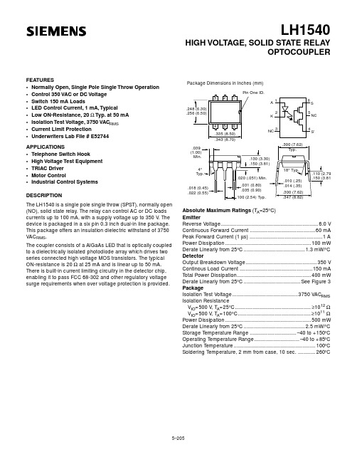
Absolute Maximum Ratings (T A =25 ° C) EmitterReverse Voltage...................................................................6.0 V Continuous Forward Current .............................................60 mA Peak Forward Current (1 µ s)..................................................1 A Power Dissipation...........................................................100 mW Derate Linearly from 25 ° C..........................................1.3 mW/ ° C DetectorOutput Breakdown Voltage.................................................350 V Continous Load Current ..................................................150 mA Total Power Dissipation...................................................400 mW Derate Linearly from 25 ° C.......................................See Figure 3 PackageIsolation Test Voltage.............................................3750 VAC RMS Isolation ResistanceV IO =500 V , T A =25 ° C.................................................... ≥ 10 12 Ω V IO =500 V , T A =100 ° C.................................................. ≥ 10 11 Ω Power Dissipation...........................................................500 mW Derate Linearly from 25 ° C..........................................2.5 mW/ ° C Storage Temperature Range ................................–40 to +150 ° C Operating Temperature Range...............................–40 to +85 ° C Junction Temperature........................................................100 ° C Soldering Temperature, 2 mm from case, 10 sec.............260 °CFEATURES•Normally Open, Single Pole Single Throw Operation •Control 350 VAC or DC Voltage •Switch 150 mA Loads•LED Control Current, 1 mA, Typical•Low ON-Resistance, 20 Ω Typ. at 50 mA •Isolation Test Voltage, 3750 VAC RMS •Current Limit Protection•Underwriters Lab File # E52744APPLICATIONS•Telephone Switch Hook•High Voltage Test Equipment •TRIAC Driver •Motor Control•Industrial Control Systems DESCRIPTION(NO), solid state relay. The relay can control AC or DC loads currents up to 100 mA, with a supply voltage up to 350 V . The device is packaged in a six pin 0.3 inch dual-in line package. This package offers an insulation dielectric withstand of 3750 VAC RMS .The coupler consists of a AlGaAs LED that is optically coupled to a dielectrically isolated photodiode array which drives two series connected high voltage MOS transistors. The typical ON-resistance is 20 Ωat 25 mA and is linear up to 50 mA. There is built-in current limiting circuitry in the detector chip, enabling it to pass FCC 68-302 and other regulatory voltage surge requirements when over voltage protection is provided.元器件交易网Characteristics (T A =25 ° C)Description Symbol Min.Typ.Max.Unit Test ConditionEmitter Forward VoltageV F 1.25 1.5V I F =10 mAV F Temperature Coefficient ∆ V F / ∆ T –2.2mV/ ° CReverse Current I R 110 µ AV R =6 VJunction Capacitance C J 15pF V F =0 V, f=1 MHz Dynamic Resistance ∆ V F / ∆ I F 6W I F =10 mA Switching Time t R , t F1µ sI F =10 mADetectorOutput Breakdown Voltage V B 350V I B =50 µ AOutput Off-State Leakage Current I T(OFF) .02200nA V T =± 100 V, I F =0 mA Feed through Capacitance, pins 4 to 6C T 55pF I F =0, f=1 KHz,V L =1 VP-P Current Limit I LMT170210250mAI F =5 mA, t=5 msPackageLED Forward Current for Turn-on I FTh 12mA I L =100 mA, t=10 ms LED Forward Current for Turn-off I FOFF 0.20.9mA V L = ± 300 V, I L =<5 µ A ON-resistance R ON 122025W I F =5 mA, I L =50 mA Turn-on Time t ON 1.2 2.0ms I F =5 mA, V L =+50 V R L =1 k ΩTurn-off Timet OFF0.52.0msFigure 2. Forward current vs. forward voltage元器件交易网Figure 6. Change in ON-resistance vs. temperature Figure 7. Change in ON-resistancevs. LED currentFigure 11. Change in t OFF vs. temperatureFigure 12. Timing test circuit and timing waveform元器件交易网。
HLMP-K155DE001中文资料

Package DimensionsA 1.52 (0.060)1.02 (0.040)BNote:1. θ1/2 is the off axis angle from lamp centerline where the luminous intensity is 1/2 the on-axis value. Part Numbering SystemHLMP-x1xx-x x x xxMechanical Option00: Bulk01: Tape & Reel, Crimped Leads02: Tape & Reel, Straight LeadsA1, B1: Right Angle Housing, Uneven LeadsA2, B2: Right Angle Housing, Even LeadsDD, DH: Ammo PackColor Bin Optioms0: Full color bin distributionMaximum Iv Bin Options0: Open (No max. limit)Others: Please refer to the Iv bin tableMinimum Iv Bin OptionsPlease refer to the Iv bin tableLens Option50: Tinted, Diffused55: Untinted, NondiffusedPackage OptionsD: T-13/4 (5 mm)K: T-1 (3 mm)Absolute Maximum Ratings at T A = 25°CPeak Forward Current[1]......................................................................................................................300 mA Average Forward Current.......................................................................................................................20 mA DC Current[2].........................................................................................................................................30 mA Power Dissipation.................................................................................................................................87 mW Reverse Voltage (I R = 100 µA)....................................................................................................................5 V Transient Forward Current (10 µs Pulse)[3].........................................................................................500 mA LED Junction Temperature.....................................................................................................................110°C Operating Temperature Range...................................................................................................-20 to +100°C Storage Temperature Range.......................................................................................................-55 to +100°C Lead Soldering Temperature [1.6 mm (0.063 in.) from body]...........................................260°C for 5 seconds Notes:1. Maximum I PEAK at f = 1 kHz, DF = 6.7%.2. Derate linearly as shown in Figure 4.3. The transient peak current is the maximum non-recurring peak current the device can withstand without damaging the LED die andwire bonds. It is not recommended that the device be operated at peak currents beyond the Absolute Maximum Peak Forward Current.Electrical/Optical Characteristics at T A = 25°CSymbol Description Min.Typ.Max.Unit Test Condition V F Forward Voltage 1.6 1.8V I F = 1 mAV R Reverse Breakdown Voltage 5.015.0V I R = 100 µAλp Peak Wavelength645nm Measurement at Peakλd Dominant Wavelength637nm Note 1∆λ1/2Spectral Line Halfwidth20nmτS Speed of Response30ns Exponential TimeConstant, e-t/T SC Capacitance30pF V F = 0, f = 1 MHzRθJ-PIN Thermal Resistance260[3]°C/W Junction to Cathode Lead210[4]290[5]ηV Luminous Efficacy80Im/W Note 2Notes:1. The dominant wavelength, λd, is derived from the CIE chromaticity diagram and represents the color of the device.2. The radiant intensity, I e, in watts per steradian, may be found from the equation I e = l V/ηV, where I V is the luminous intensity incandelas and ηV is luminous efficacy in lumens/watt.3. HLMP-D150.4. HLMP-D155.5. HLMP-K150/-K155.Figure 3. Relative Luminous Intensity vs. DC Forward Current.Figure 4. Maximum Forward DC Current vs. Ambient Temperature. Derating Based on T J Max. = 110 °C.Figure 5. Relative Luminous Intensity vs. Angular Displacement. HLMP-D150.Figure 6. Relative Luminous Intensity vs. Angular Displacement. HLMP-K150.6Maximum tolerance for each bin limit is ±18%.Mechanical Option MatrixMechanicalOption Code Definition00Bulk Packaging, minimum increment 500 pcs/bag01Tape & Reel, crimped leads, minimum increment 1300 pcs for T-13/4, 1800 pcs for T-102Tape & Reel, straight leads, minimum increment 1300 pcs for T-13/4, 1800 pcs for T-1A1T-1, Right Angle Housing, uneven leads, minimum increment 500 pcs/bagA2T-1, Right Angle Housing, even leads, minimum increment 500 pcs/bagB1T-13/4, Right Angle Housing, uneven leads, minimum increment 500 pcs/bagB2T-13/4, Right Angle Housing, even leads, minimum increment 500 pcs/bagDD Ammo Pack, straight leads with minimum 2K incrementDH Ammo Pack, straight leads with minimum 2K incrementNote:All categories are established for classification of products. Products may not be available in all categories. Please contact your local Agilent representative for further clarification/information./semiconductors For product information and a complete list of distributors, please go to our web site.For technical assistance call:Americas/Canada: +1 (800) 235-0312 or (408) 654-8675Europe: +49 (0) 6441 92460China: 10800 650 0017Hong Kong: (+65) 271 2451India, Australia, New Zealand: (+65) 271 2394 Japan: (+81 3) 3335-8152(Domestic/Interna-tional), or 0120-61-1280(Domestic Only) Korea: (+65) 271 2194Malaysia, Singapore: (+65) 271 2054Taiwan: (+65) 271 2654Data subject to change.Copyright © 2001 Agilent Technologies, Inc. Obsoletes 5968-1438ENDecember 11, 20015988-2229EN。
- 1、下载文档前请自行甄别文档内容的完整性,平台不提供额外的编辑、内容补充、找答案等附加服务。
- 2、"仅部分预览"的文档,不可在线预览部分如存在完整性等问题,可反馈申请退款(可完整预览的文档不适用该条件!)。
- 3、如文档侵犯您的权益,请联系客服反馈,我们会尽快为您处理(人工客服工作时间:9:00-18:30)。
DescriptionThese non-diffused lamps are designed to produce a bright light source and smooth radiationpattern. A slight tint is added to the lens for easy color identification.This lamp has been designed with aHLMP-C115, HLMP-C117, HLMP-C123, HLMP-C215, HLMP-C223,HLMP-C315, HLMP-C323, HLMP-C415, HLMP-C423, HLMP-C515,HLMP-C523, HLMP-C615, HLMP-C623Features•Very high intensity •Exceptional uniformity •Microtint lens for color identification•Consistent viewability All colors: AlGaAs RedHigh Efficiency Red Yellow Orange GreenEmerald Green •15° and 25° family•Tape and reel options available •Binned for color and intensity Applications•Ideal for backlighting front panels*•Used for lighting switches •Adapted for indoor and outdoor signsAgilentT-13/4 Super Ultra-Bright LED LampsData Sheet20mil lead frame, enhanced flange, and tight meniscus controls, making it compatible with radial lead automated insertion equipment.Selection GuidePart Number Luminous Intensity Iv (mcd) Color2θ1/2[1]Standoff Leads HLMP-Min.Max.DH AS AlGaAs15No C115290.0–C115-O00xx290.0–C115-OP0xx290.01000.0Yes C117-OP0xx290.01000.025No C12390.2–C123-L00xx90.2–Red15No C215138.0–C215-M00xx138.0–C215-MN0xx138.0400.025No C22390.2–C223-L00xx90.2–C223-MN0xx138.0400.0 Yellow15No C315147.0–C315-L00xx147.0–C315-LM0xx147.0424.025No C32396.2–C323-K00xx96.2–C323-KL0xx96.2294.0 Orange15No C415138.0–C415-M00xx138.0–C415-M0D0xx138.0–C415-MN0xx138.0400.025No C42390.2–C423-L00xx90.2–C423-LM0xx90.2276.0 Green15No C515170.0–C515-L00xx170.0C515-LM0xx170.0490.025No C52369.8–C523-J00xx69.8–C523-KL0xx111.7340.0 Emerald Green15No C61517.0–C615-G00xx17.0–25No C623 6.7–C623-E00xx 6.7–Part Numbering SystemHLMP - C x xx - x x x xxMechanical Options00: Bulk01: Tape & Reel, Crimped Leads02: Tape & Reel, Straight LeadsB2: Right Angle Housing, Even LeadsUQ: Ammo Pack, Horizontal LeadsColor Bin Options0: Full Color Bin DistributionD: Color Bins 4 & 5 onlyMaximum Iv Bin Options0: Open (No Maximum Limit)Others: Please refer to the Iv Bin TableMinimum Iv Bin OptionsPlease refer to the Iv Bin TableViewing Angle & Standoffs Options15: 15 Degree, without Standoffs17: 15 Degree, with Standoffs23: 25 Degree, without StandoffsColor Options1. AS AlGaAs Red2. High Efficiency Red3. Yellow4. Orange5. Green6. Emerald GreenPackage OptionsC: T-1 3/4 (5 mm)Absolute Maximum Ratings at T A = 25°CHighHighDH AS Efficiency Performance AlGaAs Red and Green and ParameterRed Orange Yellow Emerald Green Units DC Forward Current [1]30302030mA Transient Forward Current [2]500500500500mA (10 µsec Pulse)Reverse Voltage (Ir = 100 µA)5555V LED Junction Temperature 110110110110°C Operating Temperature Range –20 to +100–55 to +100–20 to +100°C Storage Temperature Range –55 to +100°CWave Soldering Temperature 250°C for 3 seconds [1.59 mm (0.063 in.) from body]Lead Solder Dipping Temperature 260°C for 5 seconds[1.59 mm (0.063 in.) from body]Notes:1. See Figure 5 for maximum current derating vs. ambient temperature.2. The transient current is the maximum nonrecurring peak current the device can withstand without damaging the LED die and wire bond.Package DimensionsHLMP-Cx15 and HLMP-Cx23HLMP-Cx17(0.039)NOTES:1. ALL DIMENSIONS ARE IN MILLIMETERS (INCHES).2. LEADS ARE MILD STEEL, SOLDER DIPPED.3. AN EPOXY MENISCUS MAY EXTEND ABOUT 0.5 mm (0.020 in.) DOWN THE LEADS.± 0.20± 0.008)Electrical Characteristics at T A = 25°CForward Reverse Capacitance Speed of ResponseVoltage Breakdown C (pF)Thermalτs (ns)Vf (Volts)Vr (Volts)Vf = 0Resistance Time Constant@ If = 20 mA@ Ir = 100 µA f = 1 MHz RθJ-PIN e-t/τsPart Number Typ.Max.Min.Typ.(°C/W)Typ.HLMP-C115 1.8 2.253021030HLMP-C117HLMP-C123HLMP-C215 1.9 2.651121090HLMP-C223HLMP-C315 2.1 2.651521090HLMP-C323HLMP-C415 1.9 2.654210280HLMP-C423HLMP-C515 2.2 3.0518210260HLMP-C523HLMP-C615 2.2 3.0518210260HLMP-C623Optical Characteristics at T A = 25°CLuminous Color,ViewingIntensity Peak Dominant Angle LuminousIv (mcd)Wavelength Wavelength2θ1/2Efficacy@ 20 mA[1]λpeak (nm)λd[2] (nm)(Degrees)[3]ηvPart Number Min.Typ.Typ.Typ.Typ.(lm/w) HLMP-C1152906006456371180HLMP-C117HLMP-C1239020026HLMP-C215138300635626171459017023HLMP-C315146300583585175009617025HLMP-C415138300600602173809017023HLMP-C515170300568570205956917028HLMP-C61517455585602065662728Notes:1. The luminous intensity, Iv, is measured at the mechanical axis of the lamp package. The actual peak of the spatial radiation pattern may not bealigned with this axis.2. The dominant wavelength, λd, is derived from the CIE Chromaticity Diagram and represents the color of the device.3. 2θ1/2 is the off-axis angle where the luminous intensity is 1/2 the on-axis intensity.Figure 1. Relative intensity vs. wavelength.Figure 2. Forward current vs. forward voltage (non-resistor lamp).Figure 3. Relative luminous intensity vs. forward current.WAVELENGTH – nmR E L A T I V E I N T E N S I T Y1.00.50I F – F O R W A R DC U R R E N T – m AV F – FORWARD VOLTAGE – VI F – F O R W A R D C U R R E N T – m AV F – FORWARD VOLTAGE – VHIGH EFFICIENCY RED, ORANGE,YELLOW, AND HIGH PERFORMANCEGREEN, EMERALD GREENR E L A T I V E L U M I N O U S I N TE N S I T Y (N O R M A L I Z E D A T 20 m A )I F – DC FORWARD CURRENT – mA R E L A T I V E L U M I N O U S I N T E N S I T Y (N O R M A L I Z E D A T 20 m A )0I DC – DC CURRENT PER LED – mA10201.60.80.4515301.2250.20.61.01.4HER, ORANGE, YELLOW, AND HIGH PERFORMANCE GREEN, EMERALD GREENFigure 5. Maximum forward dc current vs. ambient temperature. Derating based on T j MAX = 110°C.Figure 4. Relative efficiency (luminous intensity per unit current) vs. peak current.Figure 6. Relative luminous intensity vs. angular displacement. 15 degree family.R E L A T I V E E F F I C I E N C Y (N O R M A L I Z E D A T 20 m A )0I PEAK – PEAK FORWARD CURRENT – mA0.60.8300201001.21.00.20.45020010DH As AlGaAs REDηP E A K – R E L A T I V E E F F I C I E N C Y (N O R M A L I Z E D A T 20 m A )I PEAK – PEAK FORWARD CURRENT – mAHER, ORANGE, YELLOW, HIGHPERFORMANCE GREEN, EMERALD GREENI F – F O R W A R D C U R R E NT – m AT A – AMBIENT TEMPERATURE – °C DH As AlGaAs REDI F – F O R W A R D C U R R E N T – m AT A – AMBIENT TEMPERATURE – °CHER, ORANGE, YELLOW, AND HIGH PERFORMANCE GREEN, EMERALD GREEN N O R M A L I Z E D L U M I N O U S I N T E N S I T Y10ANGULAR DISPLACEMENT – DEGREES0.80.60.50.70.2450.10.30.4403530252010515-5-10-15-20-25-30-35-40-450.9Figure 7. Relative luminous intensity vs. angular displacement. 25 degree family.Intensity Bin Limits Intensity Range (mcd)ColorBin Min.Max.L 101.5162.4M 162.4234.6N 234.6340.0O 340.0540.0P 540.0850.0Q 850.01200.0R 1200.01700.0Red/OrangeS 1700.02400.0T 2400.03400.0U 3400.04900.0V 4900.07100.0W 7100.010200.0X 10200.014800.0Y 14800.021400.0Z 21400.030900.0L 173.2250.0M 250.0360.0N 360.0510.0O 510.0800.0P 800.01250.0YellowQ 1250.01800.0R 1800.02900.0S 2900.04700.0T 4700.07200.0U 7200.011700.0V 11700.018000.0W18000.027000.0N O R M A L I Z E D L U M I N O U S I N T E N S I T Y10ANGULAR DISPLACEMENT – DEGREES0.80.60.50.70.2450.10.30.4403530252010515-5-10-15-20-25-30-35-40-450.9Intensity Bin Limits, continuedIntensity Range (mcd) Color Bin Min.Max.E7.612.0F12.019.1G19.130.7H30.749.1I49.178.5J78.5125.7K125.7201.1L201.1289.0 Green/M289.0417.0 Emerald Green N417.0680.0O680.01100.0P1100.01800.0Q1800.02700.0R2700.04300.0S4300.06800.0T6800.010800.0U10800.016000.0V16000.025000.0W25000.040000.0 Maximum tolerance for each bin limit is ± 18%.Color CategoriesLambda (nm)Color Category #Min.Max.6561.5564.55564.5567.5 Green4567.5570.53570.5573.52573.5576.51582.0584.53584.5587.0 Yellow2587.0589.54589.5592.05592.0593.01597.0599.52599.5602.03602.0604.5 Orange4604.5607.55607.5610.56610.5613.57613.5616.58616.5619.5 Tolerance for each bin limit is ± 0.5 nm.Mechanical Option MatrixMechanical Option Code Definition00Bulk Packaging, minimum increment 500 pcs/bag01Tape & Reel, crimped leads, minimum increment 1300 pcs/bag02Tape & Reel, straight leads, minimum increment 1300 pcs/bagB2Right Angle Housing, even leads, minimum increment 500 pcs/bagUQ Ammo Pack, horizontal leads, in 1K minimum incrementNote:All categories are established for classification of products. Products may not be available in all categories. Please contact your local Agilent representative for further clarification/information./semiconductorsFor product information and a complete list ofdistributors, please go to our web site.For technical assistance call:Americas/Canada: +1 (800) 235-0312 or(916) 788-6763Europe: +49 (0) 6441 92460China: 10800 650 0017Hong Kong: (+65) 6756 2394India, Australia, New Zealand: (+65) 6755 1939Japan: (+81 3) 3335-8152 (Domestic/Interna-tional), or 0120-61-1280 (Domestic Only)Korea: (+65) 6755 1989Singapore, Malaysia, Vietnam, Thailand,Philippines, Indonesia: (+65) 6755 2044Taiwan: (+65) 6755 1843Data subject to change.Copyright © 2004 Agilent Technologies, Inc.Obsoletes 5965-6165ENovember 11, 20045988-2149EN。