HLMP-Q106GG012中文资料
数据手册_HR6P60HL_Datasheet_C V2.2
关于芯片的开发环境
海尔 MCU 芯片具有完整的软/硬件开发环境,并受知识产权保护。选择上海海尔集成电路有限公司或其指 定的第三方公司的汇编器、编译器、编程器、硬件仿真器开发环境,必须遵循与芯片相关的规定和说明。
注:在产品开发时,如遇到不清楚的地方,请用下述联系方式与上海海尔集成电路有限公司联系。
V2.2 版权所有©上海海尔集成电路有限公司
关于芯片的 ESD 防护措施
海尔 MCU 芯片具有满足工业级 ESD 标准保护电路。 建议用户根据芯片存储/应用的环境采取适当静电防护 措施。应注意应用环境的湿度;建议避免使用容易产生静电的绝缘体;存放和运输应在抗静电容器、抗静 电屏蔽袋或导电材料容器中;包括工作台在内的所有测试和测量工具必须保证接地;操作者应该佩戴静电 消除手腕环手套,不能用手直接接触芯片等。
HR6P60HL 数据手册
海尔 MCU 芯片使用注意事项
关于芯片的上/下电 海尔 MCU 芯片具有独立电源管脚。当 MCU 芯片应用在多电源供电系统时,应先对 MCU 芯片上电,再 对系统其他部件上电;反之,下电时,先对系统其他部件下电,再对 MCU 芯片下电。若操作顺序相反则
可能导致芯片内部元件过压或过流,从而导致芯片故障或元件退化。具体可参照芯Hale Waihona Puke 的数据手册说明。关于芯片的时钟
海尔 MCU 芯片具有内部和外部时钟源。内部时钟源会随着温度、电压变化而偏移,可能会影响时钟源精 度;外部时钟源采用陶瓷、晶体振荡器电路时,建议使能起振延时;使用 RC 振荡电路时,需考虑电容、 电阻匹配; 采用外部有源晶振或时钟输入时, 需考虑输入高/低电平电压。 具体可参照芯片的数据手册说明。
3. 2
第 4 章 4. 1 4. 2 4. 3 4. 4 4. 5
本特利使用说明书.

BH5000网络化实时监测诊断系统 ====使用指南 ====版本:V4.6.0.4北京博华信智科技发展有限公司2014年 04月目录1前言 .................................................................................................................. 1 1.1标识 (2)1.2BH5000网络化实时监测系统概 ................................................................... 2 1.2.1实时监测系统功能 .......................................................................................... 2 1.2.2实时监测系统特性 (3)1.3BH5000客户端软件概述 (4)2客户端软件的安装和配置 .............................................................................. 5 2.1客户端软件的安装 (5)2.2客户端软件的配置 (7)3基本操作指南 ................................................................................................ 10 3.1系统登录 ........................................................................................................ 10 3.2界面总览 ........................................................................................................ 10 3.3菜单栏 ............................................................................................................ 11 3.4快捷工具栏 .................................................................................................... 13 3.5功能模块抽屉式菜单栏 ................................................................................ 14 3.6导航栏 ............................................................................................................ 15 3.7绘图工具栏 .................................................................................................... 15 3.8操作页 ............................................................................................................ 16 3.9信息页 ............................................................................................................ 16 3.10图谱操作 ........................................................................................................ 17 3.10.1图谱新增毫秒显示 ........................................................................................ 17 3.10.2游标 ................................................................................................................ 17 3.10.3标注 ................................................................................................................ 17 3.10.4同步标注 ........................................................................................................ 18 3.10.5标点 ................................................................................................................ 18 3.10.6趋势操作 ........................................................................................................ 19 3.10.7复位 ................................................................................................................ 19 3.10.8打印 ................................................................................................................ 20 3.10.9保存图形 ........................................................................................................ 20 3.10.10切换 ................................................................................................................ 21 3.10.11显示报警线 .................................................................................................... 22 3.10.12纵坐标自动调整 ............................................................................................ 22 3.10.13锁定坐标 ........................................................................................................ 23 3.10.14手动修改坐标 (23)3.10.15图谱放大,关联更新 (24)3.10.16滚轮放大 (24)3.10.17自定义图谱布局 (25)3.10.18三维图谱 (26)3.10.19双击时间戳画图 (27)3.11设备树显示报警 ............................................................................................ 27 3.12设备树启停车状态显示 ................................................................................ 27 3.13设备树显示断网状态 .................................................................................... 28 3.14设备切换 ........................................................................................................ 28 3.15背景提示图 .................................................................................................... 29 3.16服务器状态切换 .. (30)3.17设备采集状态设置 (33)4旋转机械专用图谱 ........................................................................................ 34 4.1机组概貌图 .................................................................................................... 34 4.2振动监测 ........................................................................................................ 35 4.3振动历史比较图 ............................................................................................ 37 4.4单多值棒图 .................................................................................................... 38 4.5轴心轨迹 ........................................................................................................ 39 4.6轴心位置 ........................................................................................................ 42 4.7启停车图形 .................................................................................................... 43 4.8综合分析 ........................................................................................................ 45 4.9运行状态图 .................................................................................................... 49 4.10其它参数趋势图 ............................................................................................ 51 4.11全频谱 ............................................................................................................ 52 4.12二维全息谱图 ................................................................................................ 53 4.13三维全息谱图 ................................................................................................ 54 4.14旋转报警查询 (55)4.15现场动平衡 (57)5临时在线专用图谱 ........................................................................................ 59 5.1机组概貌图 .................................................................................................... 59 5.2动平衡响应分析 ............................................................................................ 59 5.3试车分析 ........................................................................................................ 60 5.4振动监测 ........................................................................................................ 62 5.5振动历史比较图 ............................................................................................ 62 5.6单多值棒图 (62)5.7轴心轨迹 (63)5.8轴心位置 ........................................................................................................ 63 5.9综合分析 ........................................................................................................ 63 5.10运行状态图 .................................................................................................... 63 5.11其他参数趋势图 ............................................................................................ 63 5.12旋转报警查询 ................................................................................................ 63 5.13全频谱图 ........................................................................................................ 63 5.14二维全息谱图 ................................................................................................ 63 5.15三维全息谱图 ................................................................................................ 63 5.16现场动平衡 (64)5.17倒谱图 (64)6往复机械专用图谱 ........................................................................................ 64 6.1机组概貌图 .................................................................................................... 64 6.2运行状态图 .................................................................................................... 65 6.3历史比较图 .................................................................................................... 67 6.4单值棒图 ........................................................................................................ 68 6.5活塞杆沉降 /偏摆监测 .................................................................................. 70 6.6活塞杆轨迹图 ................................................................................................ 71 6.7振动监测 ........................................................................................................ 72 6.8多参数分析 .................................................................................................... 74 6.9示功图 ............................................................................................................ 75 6.10综合监测 ........................................................................................................ 76 6.11其它参数趋势图 ............................................................................................ 77 6.12往复报警查询 ................................................................................................ 79 6.13应力监测 (80)6.14冲击诊断 (81)7风电专用图谱 ................................................................................................ 83 7.1机组概貌图 .................................................................................................... 83 7.2趋势分析 ........................................................................................................ 84 7.3冲击诊断 ........................................................................................................ 86 7.4转子类故障诊断 ............................................................................................ 89 7.5倒谱图 ............................................................................................................ 90 7.6单多值棒图 .................................................................................................... 92 7.7其它参数趋势图 ............................................................................................ 93 7.8风电报警查询 (94)8机泵专用图谱 ................................................................................................ 95 8.1机组概貌图 .................................................................................................... 96 8.2趋势分析 ........................................................................................................ 97 8.3冲击诊断 ........................................................................................................ 98 8.4转子类故障诊断 .......................................................................................... 101 8.5倒谱图 .......................................................................................................... 103 8.6单多值棒图 .................................................................................................. 104 8.7其它参数趋势图 (105)8.8机泵报警查询 (106)9在线报告报表 .............................................................................................. 108 9.1监测诊断报告 .............................................................................................. 108 9.2机组月报表 .................................................................................................. 110 9.3厂级报表 ...................................................................................................... 113 9.4振动参数报表 .............................................................................................. 113 10案例库模块 .................................................................................................. 115 10.1案例录入 ...................................................................................................... 115 10.1.1添加案例 ...................................................................................................... 117 10.1.2修改案例 ...................................................................................................... 121 10.1.3取消案例 ...................................................................................................... 121 10.2案例查询 ...................................................................................................... 121 10.2.1案例查询 ...................................................................................................... 122 10.2.2导出word .................................................................................................... 122 10.3案例审核 ...................................................................................................... 123 10.3.1案例查询 ...................................................................................................... 123 10.3.2修改案例 ...................................................................................................... 124 10.3.3审核案例 ...................................................................................................... 124 10.4检维修记录管理 .......................................................................................... 125 10.4.1添加检维修记录 .......................................................................................... 126 10.4.2修改检维修记录 .......................................................................................... 126 10.4.3删除检维修记录 .......................................................................................... 126 10.4.4导出word .................................................................................................... 127 10.5开停车记录管理 .......................................................................................... 127 10.5.1查询原始开停车记录 .................................................................................. 127 10.5.2添加开停车记录 .......................................................................................... 128 10.5.3修改开停车记录 (128)10.5.4删除开停车记录 .......................................................................................... 128 10.5.5开停车记录查询 (129)10.6基于案例诊断 (129)10.6.1诊断条件 (129)10.6.2相似度判断 .................................................................................................. 129 11系统维护和系统故障诊断 .......................................................................... 130 11.1客户端无法登陆 .......................................................................................... 130 11.2客户端看不到概貌图 .................................................................................. 131 11.3客户端提示请选择测点 .............................................................................. 131 11.4添加图谱出错 .............................................................................................. 131 11.5客户端查看不到历史数据库或不保存历史数据 ...................................... 131 11.6客户端图谱单位不正确 .............................................................................. 132 11.7客户端测点缸号不正确 .............................................................................. 132 11.8客户端不报警 .............................................................................................. 132 12附录 .............................................................................................................. 132 12.1旋转机械振动机理和诊断方法 .................................................................. 133 12.1.1机械设备振动监测的主要参数和定义 ...................................................... 133 12.1.2机械设备振动分析常用手段 . (138)1前言状态监测与故障诊断是在设备运行中或在基本不拆卸的情况下, 通过各种手段,掌握设备的运行状态,判定设备产生故障的部位和原因,并预测、预报设备未来的运行状态。
HLMP-Q106FG011中文资料

Agilent Subminiature High Performance TS AlGaAs Red LED Lamps Data SheetFeatures•Subminiature flat top package Ideal for backlighting and light piping applications•Subminiature dome package Diffused dome for wide viewing angleNon-diffused dome for high brightness•Wide range of drive currents500 µA to 50 mA •Ideal for space limited Applications •Axial leads•Available with lead configurations for surface mount and through hole PC board mountingDescriptionFlat Top PackageThe HLMP-Pxxx Series flat top lamps use an untinted, non-diffused, truncated lens toprovide a wide radiation pattern that is necessary for use in backlighting applications. The flat top lamps are also ideal for use as emitters in light pipe applications.Dome PackagesThe HLMP-Qxxx Series dome lamps, for use as indicators, use a tinted, diffused lens to provide a wide viewing angle with high on-off contrast ratio. High brightness lamps use anuntinted, nondiffused lens to provide a high luminous inten-sity within a narrow radiation pattern.Lead ConfigurationsAll of these devices are made by encapsulating LED chips onaxial lead frames to form molded epoxy subminiature lamppackages. A variety of package configuration options isavailable. These include special surface mount lead configura-tions, gull wing, yoke lead, or Z-bend. Right angle lead bends at 2.54 mm (0.100 inch) and 5.08mm (0.200 inch) center spacing are available for through hole mounting. For more information refer to Standard SMT and Through Hole Lead BendOptions for Subminiature LED Lamps data sheet.TechnologyThese subminiature solid state lamps utilize a highly optimized LED material technology,transparent substrate aluminum gallium arsenide (TS AlGaAs).This LED technology has a very high luminous efficiency,capable of producing high light output over a wide range of drive currents (500 µA to 50mA). The color is deep red at a dominant wavelength of 644nm deep red. TS AlGaAs is a flip-chip LED technology, dieattached to the anode lead and wire bonded to the cathode lead.Available viewing angles are 75°, 35°, and 15°.HLMP-P106/P156HLMP-Q102/Q152HLMP-Q106/Q156Device Selection GuideViewing Angle Deep Red Typical Iv Typical IvPackage Description 2 q1/2R d = 644 nm I F = 500 µa I F = 20 mA Package Outline Domed, Diffused Tinted,35HLMP-Q102100BStandard CurrentDomed, Diffused Tinted,35HLMP-Q1522BLow CurrentDomed, Nondiffused15HLMP-Q106400BUntinted, Standard CurrentDomed, Nondiffused15HLMP-Q1567BUntinted, Low CurrentFlat Top, Nondiffused,75HLMP-P106130AUntinted, Standard CurrentFlat Top, Nondiffused75HLMP-P1562AUntinted, Low CurrentOrdering InformationHLMX-XXXX-X X X X XPackagingOptionColor BinSelectionMax. Iv BinMin. Iv Bin4 x 4 Prod.PartNumberFigure 1. Proper right angle mounting to a PC board to prevent protruding anode tab from shorting to cathode c onnection.Package Dimensions A) Flat Top LampsB) Diffused and Nondiffused Dome LampsNO. CATHODE DOWN.YES. ANODE DOWN.* REFER TO FIGURE 1 FOR DESIGN CONERNS.2.082.34(0.082)(0.092)2.082.34(0.082)(0.092)0.53 (0.021)2.211.96(0.087)(0.077)NOTES:1. ALL DIMENSIONS ARE IN MILLIMETRES (INCHES).2. PROTRUDING SUPPORT TAB IS CONNECTED TO ANODE LEAD.3. LEAD POLARITY FOR THESE TS AlGaAs SUBMINIATURE LAMPS IS OPPOSITE TO THE LEAD POLARITY OF SUBMINIATURE LAMPS USING OTHER LED TECHNOLOGIES.Absolute Maximum Ratings at T A = 25°CParameters TitleDC Forward Current[1]50 mAPeak Forward Current[2]300 mAAverage Forward Current[2,3]30 mATransient Forward Current (10 µs Pulse)[4]500 mAPower Dissipation100 mWReverse Voltage 5 VJunction Temperature110°COperating Temperature-55°C to +100°CStorage Temperature-55°C to +100°CLead Soldering Temperature260°C for 5 seconds[1.6 mm (0.063 in.) from body]Reflow Soldering Temperature260°C for 20 secondsNotes:1. Derate linearly as shown in Figure 6.2. Refer to Figure 7 to establish pulsed operating conditions.3. Maximum IAVG at f = 1 kHz, DF = 10%.4. The transient peak current is the maximum non-recurring peak current the device can withstandwithout damaging the LED die and wire bonds. It is not recommended that the device beoperated at peak currents above the Absolute Maximum Peak Forward Current.Optical Characteristics at T A = 25°CLuminous Intensity Total Flux Peak Color, Dominant Viewing Angle LuminousI V (mcd)f V (mlm)Wavelength Wavelength2q1/2Efficacy Part Number@ 20 mA[1]@ 20 mA[2]l peak (nm)l d[3] (nm)Degrees[4]h v[5] HLMP-Min.Typ.Typ.Typ.Typ.Typ.(lm/w) Q106-R00xx1004002806546441585Q102-N00xx25100-6546443585P106-Q00xx631302806546447585Optical Characteristics at T A = 25°CLuminous Intensity Total Flux Peak Color, Dominant Viewing Angle Luminous Part Number I V (mcd)f V (mlm)Wavelength Wavelength2f1/2Efficacy (Low Current)@ 0.5 mA[1]@ 0.5 mA[2]l peak (nm)l d[3] (nm)Degrees[4]h v[5] HLMP-Min.Typ.Typ.Typ.Typ.Typ.(lm/w) Q156-H00xx 2.5710.56546441585Q152-G00xx 1.62-6546443585P156-EG0xx0.63210.56546447585 Notes:1. The luminous intensity, Iv, is measured at the mechanical axis of the lamp package. The actual peak of the spatial radiation pattern may not bealigned with this axis.2. f v is the total luminous flux output as measured with an integrating sphere.3. The dominant wavelength, l d, is derived from the CIE Chromaticity Diagram and represents the color of the device.4. q1/2 is the off-axis angle where the liminous intensity is 1/2 the peak intensity.5. Radiant intensity, I v, in watts/steradian, may be calculated from the equation I v = I v/h v, where I v is the luminous intensity in candelas and h v is theluminous efficacy in lumens/watt.Electrical Characteristics at T A = 25°CCapacitanceSpeed of Response Forward Voltage Reverse Breakdown C (pF)t s (ns)Part V F (Volts)V R (Volts)V F = 0,Thermal Time Constant Number @ I F = 20 mA @ I R = 100 µA f = 1 MHz Resistance e -t/t s HL MP-Typ. M ax.Min. Typ.Typ.R q J-PIN (°C/W)Typ.Q106 1.9 2.45202017045Q102 1.9 2.45202017045P1061.92.45202017045Electrical Characteristics at T A = 25°C Part CapacitanceSpeed of Response Number Forward Voltage Reverse Breakdown C (pF)t s (ns)(Low V F (Volts)V R (Volts)V F = 0,Thermal Time Constant Current)@ I F = 0.5 mA @ I R = 100 µA f = 1 MHz Resistance e -t/t s HL M P-Typ. M ax.M in. Typ.Typ.R q J-PIN (°C/W)Typ.Q156 1.6 1.95202017045Q152 1.6 1.95202017045P1561.61.95202017045Figure 5. Relative efficiency vs. peak forward current.Figure 7. Maximum average current vs. peak forward current.Figure 6. Maximum forward DC current vs.ambient temperature. Derating based on T J MAX = 110°C.ηV – R E L A T I V E E F F I C I E N C Y (N O R M A L I Z E D A T 20 m A )53000.0I PEAK – PEAK FORWARD CURRENT – mA 102050100212000.10.20.30.40.50.60.70.80.91.01.11.2Figure2. Relative intensity vs. wavelength.Figure 4. Relative luminous intensity vs. DC forward current.Figure 3. Forward current vs. forward voltage.R E L A T I V E I N T E N S I T Y 600100010-3WAVELENGTH – nm70050010-210-11.0R E L A T I V E L U M I N O U S I N T E N S I T Y (N O R M A L I Z E D A T 20 m A )20.50.01I F – DC FORWARD CURRENT – mA51020502.42.01.00.20.10.0510.5I F – F O R W A R D C U R R E N T – m A1.03.5300201V F – FORWARD VOLTAGE – V1.52.02.53.02001005010520.5I A V G = A V E R A G E F O R W A R D C U R R E N T – m AI PEAK – PEAK FORWARD CURRENT – mAI F – F O R W A R D C U R R E N T – m AT A – AMBIENT TEMPERATURE – °CN O R M A L I Z E D I N T E N S I T Y1.00ANGULAR DISPLACEMENT – DEGREES0.80.60.50.70.2100°90°0.10.30.480°70°60°50°40°20°10°0°30°10°20°30°40°50°60°70°80°90°100°0.9Figure 8. HLMP-Q106/-Q156.N O R M A L I Z E D I N T E N S I T Y1.00ANGULAR DISPLACEMENT – DEGREES0.80.60.50.70.2100°90°0.10.30.480°70°60°50°40°20°10°0°30°10°20°30°40°50°60°70°80°90°100°0.9Figure 9. HLMP-Q102/-Q152N O R M A L I Z E D I N T E N S I T Y1.00ANGULAR DISPLACEMENT – DEGREES0.80.60.50.70.2100°90°0.10.30.480°70°60°50°40°20°10°0°30°10°20°30°40°50°60°70°80°90°100°0.9Figure 10. HLMP-P106/-P156.Intensity Bin LimitsBin Min.Max.E0.63 1.25F 1.00 2.00G 1.60 3.20H 2.50 5.00J 4.008.00K 6.3012.50L10.0020.00M16.0032.00N25.0050.00P40.0080.00Q63.00125.00R100.00200.00S160.00320.00T250.00500.00U400.00800.00V630.001250.00W1000.002000.00X1600.003200.00Y2500.005000.00Color Bin LimitsPackage Bin Min.Max.Red0Full DistributionMechanical Option00Straight Leads, Bulk Packaging, Quantity of 500 Parts11Gull Wing Leads, 12 mm Tape on 7 in. Dia. Reel, 1500 Parts per Reel 12Gull Wing Lead, Bulk Packaging, Quantity of 500 Parts14Gull Wing Leads, 12 mm Tape on 13 in. Dia. Reel, 6000 Parts per Reel 21Yoke Leads, 12 mm Tape on 7 in. Dia. Reel, 1500 Parts per Reel22Yoke Leads, Bulk Packaging, Quantity of 500 Parts24Yoke Leads, 12 mm Tape on 13 in. Dia. Reel, 6000 Parts per Reel31Z-Bend Leads, 12 mm Tape on 7 in. Dia. Reel, 1500 Parts per Reel32Z-Bend Leads, Bulk Packaging, Quantity of 500 Parts34Z-Bend Leads, 12 mm Tape on 13 in. Dia. Reel, 6000 Parts per Reel Note:All Categories are established for classification of products. Products may not be available in all categories. Please contact your local Agilent representative for further clarification/information./semiconductors For product information and a complete list of distributors, please go to our web site.For technical assistance call:Americas/Canada: +1 (800) 235-0312 or (916) 788-6763Europe: +49 (0) 6441 92460China: 10800 650 0017Hong Kong: (+65) 6756 2394India, Australia, New Zealand: (+65) 6755 1939 Japan: (+81 3) 3335-8152(Domestic/Interna-tional), or 0120-61-1280(Domestic Only) Korea: (+65) 6755 1989Singapore, Malaysia, Vietnam, Thailand, Philippines, Indonesia: (+65) 6755 2044 Taiwan: (+65) 6755 1843Data subject to change.Copyright © 2005 Agilent Technologies, Inc. Obsoletes 5930-2437EJanuary 18, 20055989-1711EN。
艾默生UPS电源专项培训-6脉冲和12脉冲技术差别
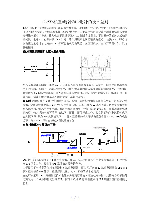
120KVA 机型6脉冲和12脉冲的技术差别6脉冲指以6个可控硅(晶闸管)组成的全桥整流,由于有6个开关脉冲对6个可控硅分别控制,所以叫6脉冲整流。
一般三相电使用6脉冲整流时,由于晶闸管只在交流电压波形幅值大于直流母线电压时才导通,输入电流不连续呈脉冲状,谐波含量很高,不加额外的滤波方式如无源滤波(电感)、有源滤波(PFC )时,输入反馈回电网的谐波电流总THD 超过30%,即总谐波电流含量超过总电流的33%,有可能造成配电线缆、变压器发热,空气开关误动作,发电机喘振等。
6脉冲整流原理图和电流电压效果图:加入无源滤波器即校正电感后,才可将输入电流谐波含量降至10%左右。
但这仅仅是满载情况下的指标。
实际上,越是轻载情况,6脉冲整流器的输入谐波电流含量就越大,比如50%负载情况下,6脉冲整流器的输入谐波电流总含量超过56%;25%负载情况下,则超过78%。
也就是说,谐波的绝对值基本不随负载量的减轻而减少。
12脉冲是指在原有6脉冲整流的基础上,在输入端增加移相变压器后在增加一组6脉冲整流器,使直流母线电流由12个可控硅整流完成,因此又称为12脉冲整流。
它使整流器导通角大幅增加,输入电流更平滑,谐波电流含量减少,一般可达到10%左右,在增加无源电感滤波后,输入谐波电流可降至4%以下。
而且,即使轻载工作,其良好的输入电流特性也不会大幅下降。
比如50%负载情况下,12脉冲整流器的输入谐波电流总含量<12%;25%负载情况下,则<15%。
可以有效减少谐波的绝对值。
12脉冲整流UPS 原理如下图:自动旁路移相变压器L+L-电池开关内置手动维修旁路UPS 1电池SCRSCR6脉冲整流器6脉冲整流器UPS 中有并联冗余的2个6脉冲整流器,所以,其工作时即使有一个整流器故障,也不会影响UPS 正常工作,提高了UPS 系统的故障容错能力。
由于使用了全功率的移相变压器和6脉冲整流器,所以同厂家的12脉冲整流器的UPS 比6脉冲整流器的UPS 体积、重量都要大至少1/3。
AEC-Q100 G 中文版

基于集成电路应力测试认证的失效机理内容列表AEC-Q100 基于集成电路应力测试认证的失效机理附录1:认证家族的定义附录2:Q100设计、架构及认证的证明附录3:邦线测试的塑封开启附录4:认证计划和结果的最低要求附录5:决定电磁兼容测试的零件设计标准附录6:决定软误差测试的零件设计标准附件AEC-Q100-001 邦线切应力测试AEC-Q100-002 人体模式静电放电测试AEC-Q100-003 机械模式静电放电测试AEC-Q100-004 集成电路闩锁效应测试AEC-Q100-005 可写可擦除的永久性记忆的耐久性、数据保持及工作寿命的测试 AEC-Q100-006 热电效应引起的寄生闸极漏电流测试AEC-Q100-007 故障仿真和测试等级AEC-Q100-008 早期寿命失效率(ELFR)AEC-Q100-009 电分配的评估AEC-Q100-010 锡球剪切测试AEC-Q100-011 带电器件模式的静电放电测试AEC-Q100-012 12V系统灵敏功率设备的短路可靠性描述感谢任何涉及到复杂技术的文件都来自于各个方面的经验和技能,为此汽车电子委员会由衷承认并感谢以下对该版文件有重要贡献的人:固定会员:准会员:特邀会员:其他支持者:注意事项AEC文件中的材料都是经过了AEC技术委员会所准备、评估和批准的。
AEC文件是为了服务于汽车电子工业,无论其标准是用在国内还是国际上,都可排除器件制造商和采购商之间各方面的不一致性,推动产品的提高和可交换性,还能帮助采购商在最小的时间耽搁内选择和获得来自那些非AEC成员的合适的产品。
AEC文件并不关注其采纳的内容是否涉及到专利、文章、材料或工艺。
AEC 没有认为对专利拥有者承担责任,也没有认为要对任何采用AEC文件者承担义务。
汽车电子系统制造商的观点主要是AEC文件里的信息能为产品的说明和应用提供一种很完美的方法。
如果没有在本文件见到所陈述的要求,就不能声称与本文件具有一致性。
HPMLDL系列服务器

HPMLDL系列服务器hpML系列服务器HP ProLiant ML110G7(C8R00A)参数规格差不多参数产品类型工作组级产品类别塔式产品结构4U处理器CPU类型奔腾双核CPU型号奔腾双核G860CPU频率3GHzHP ProLiant ML330 G6(600911-AA1)参数规格差不多参数产品类型企业级产品类别塔式产品结构5U处理器CPU类型Intel 至强5600CPU型号Xeon E5620CPU频率 2.4GHz智能加速主2.666GHz频标配CPU1颗数量最大CPU2颗数量制程工艺32nm三级缓存12MB总线规格QPI 5.86GT/sCPU核心四核HP ProLiant ML330 G6(B9D22A)参数规格差不多参数产品类型企业级产品类别塔式产品结构5U处理器CPU类型Intel 至强5600 CPU型号Xeon E5606CPU频率 2.13GHz标配CPU1颗数量最大CPU2颗数量制程工艺32nm三级缓存8MB总线规格QPI 4.8GT/sHP ProLiant ML330 G6(600911-AA1)参数规格差不多参数产品类型企业级产品类别塔式产品结构5U处理器CPU类型Intel 至强5600CPU型号Xeon E5620CPU频率 2.4GHz智能加速主2.666GHz频标配CPU1颗数量最大CPU2颗数量制程工艺32nm三级缓存12MB总线规格QPI 5.86GT/sCPU核心四核HP ProLiant ML350 G6(638180-AA1)参数规格差不多参数产品类别塔式产品结构5U处理器CPU类型Intel 至强5600CPU型号Xeon E5606CPU频率 2.13GHz标配CPU1颗数量最大CPU2颗数量制程工艺32nm三级缓存8MB总线规格QPI 4.8GT/sCPU核心四核CPU线程四线程数主板HP ProLiant ML350 G6(600431-AA5)参数规格差不多参数产品类别塔式产品结构5U处理器CPU类型Intel 至强5600CPU型号Xeon E5620CPU频率 2.4GHz智能加速主2.666GHz频标配CPU1颗数量最大CPU2颗数量制程工艺32nm三级缓存12MB总线规格QPI 5.86GT/sCPU核心四核CPU线程八线程数HP ProLiant ML350 G6(594869-AA1)参数规格差不多参数产品类别塔式产品结构5U处理器CPU类型Intel 至强5600CPU型号Xeon E5620CPU频率 2.4GHz智能加速主2.666GHz频标配CPU1颗数量最大CPU2颗数量制程工艺32nm三级缓存12MB总线规格QPI 5.86GT/sCPU核心四核CPU线程八线程数HP ProLiant ML310e Gen8(686146-AA5)参数规格差不多参数产品类型企业级产品类别塔式产品结构4U处理器CPU类型Intel 至强E3-1200 v2 CPU型号Xeon E3-1220 v2CPU频率 3.1GHz标配CPU1颗数量最大CPU4颗数量制程工艺22nm三级缓存8MB总线规格DMI 5GT/sHP ProLiant ML310e Gen8(686147-AA5)参数规格差不多参数产品类型企业级产品类别塔式产品结构4U处理器CPU类型Intel 至强E3-1200 v2 CPU型号Xeon E3-1240 v2CPU频率 3.4GHz智能加速主3.8GHz频标配CPU1颗数量最大CPU4颗数量制程工艺22nm三级缓存8MBHP ProLiant ML350e Gen8(C3Q10A)参数规格差不多参数产品类型企业级产品类别塔式产品结构5U处理器CPU类型Intel 至强E5-2400 CPU型号Xeon E5-2403CPU频率 1.8GHz标配CPU1颗数量最大CPU4颗数量制程工艺32nm三级缓存10MB总线规格QPI 6.4GT/sHP ProLiant ML350e Gen8(C3Q08A)参数规格差不多参数产品类型企业级产品类别塔式产品结构5U处理器CPU类型Intel 至强E5-2400 CPU型号Xeon E5-2407CPU频率 2.2GHz标配CPU1颗数量最大CPU4颗数量制程工艺32nm三级缓存10MB总线规格QPI 6.4GT/sHP ProLiant ML350e Gen8(C3Q09A)参数规格差不多参数产品类型企业级产品类别塔式产品结构5U处理器CPU类型Intel 至强E5-2400 CPU型号Xeon E5-2420CPU频率 1.9GHz标配CPU1颗数量最大CPU4颗数量制程工艺32nm三级缓存15MB总线规格QPI 6.4GT/sHP ProLiant ML350e Gen8(C3F91A)参数规格差不多参数产品类型企业级产品类别塔式产品结构5U处理器CPU类型Intel 至强E5-2400 CPU型号Xeon E5-2430CPU频率 2.2GHz标配CPU1颗数量最大CPU4颗数量制程工艺32nm三级缓存15MB总线规格QPI 6.4GT/sHP ProLiant ML350p Gen8(646675-AA1)参数规格差不多参数产品类别塔式产品结构5U处理器CPU类型Intel 至强E5-2600 CPU型号Xeon E5-2609CPU频率 2.4GHz标配CPU1颗数量最大CPU2颗数量制程工艺32nm三级缓存10MB总线规格QPI 6.4GT/sHP ProLiant ML350p Gen8(668271-AA5)参数规格差不多参数产品类别塔式产品结构5U处理器CPU类型Intel 至强E5-2600 CPU型号Xeon E5-2620CPU频率2GHz智能加速主2.5GHz频标配CPU1颗数量最大CPU2颗数量制程工艺32nm。
霍尼韦尔商业开关与传感器说明书
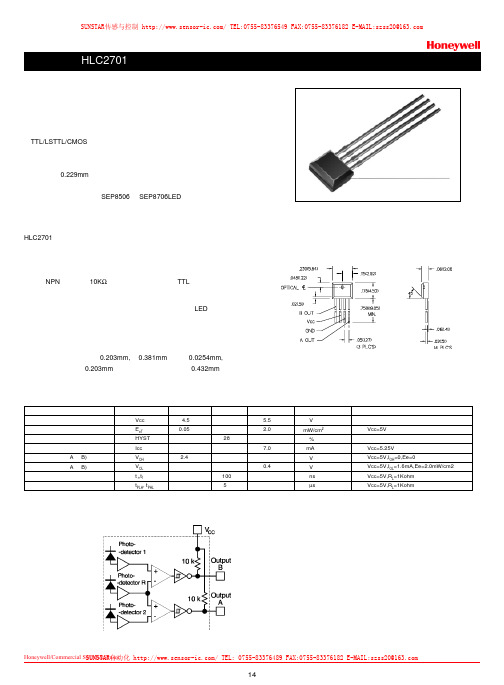
14Honeywell/Commercial Switch&Sensor 霍尼韦尔商业开关与传感器特点侧接收塑料封装TTL/LSTTL/CMOS 兼容反向逻辑输出线性或旋转编码器应用分辨率为0.229mm具有灵敏度温度补偿机械结构上和光谱上与SEP8506和SEP8706LED 相匹配HLC2701专为感测机械运动的速度和方向而设计。
应用包括旋转编码器或线位移编码器。
特别适用于光学鼠标中的编码器。
探测器为单片集成电路包括两个非常靠近的光电二极管、放大器和施密特触发器输出单元。
输出为NPN 集电极带10K Ω上拉电阻,可直接驱动TTL 负载。
探测器中具有灵敏度温度补偿电路,来补偿由于温度变化LED输出功率的漂移。
集成电路封装在一个模压不透光的黑色塑料壳中,可以透射红外能量,而阻挡可见光的透射。
集成电路的敏感区每个宽0.203mm,高0.381mm ,间隔0.0254mm,中心到中心的间隔为0.203mm ,外部边缘到边缘的距离为0.432mm 。
电参数参数供电电压导通辐射阈值迟滞供电电流高电平输出电压(A 和B)低电平输出电压(A 和B)输出上升时间和下降传播延迟,低-高,高-低符号Vcc E eT HYST Icc V OH V OL t r ,t f t PLH , t PHL 最小值 4.5 0.05 2.4典型值 28 100 5最大值 5.5 2.0 7.0 0.4 单位V mW/cm2 % mA V V ns µs 测试条件Vcc=5V Vcc=5.25V Vcc=5V,I OH =0,Ee=0Vcc=5V,I OL =1.6mA,Ee=2.0mW/cm2Vcc=5V,R L =1Kohm Vcc=5V,R L =1Kohm 功能框图外形尺寸图,单位为英寸(毫米)SUNSTAR传感与控制/TEL:0755-********FAX:0755-********E-MAIL:**************SUNSTAR自动化/TEL:0755-********FAX:0755-********E-MAIL:**************公司由传感器销售部、仪表销售部、工程部和总务部四个部组成。
ENA1P-B28-L00128L中文资料(bourns)中文数据手册「EasyDatasheet - 矽搜」

- 1、下载文档前请自行甄别文档内容的完整性,平台不提供额外的编辑、内容补充、找答案等附加服务。
- 2、"仅部分预览"的文档,不可在线预览部分如存在完整性等问题,可反馈申请退款(可完整预览的文档不适用该条件!)。
- 3、如文档侵犯您的权益,请联系客服反馈,我们会尽快为您处理(人工客服工作时间:9:00-18:30)。
Agilent Subminiature High Performance TS AlGaAs Red LED Lamps Data SheetFeatures•Subminiature flat top package Ideal for backlighting and light piping applications•Subminiature dome package Diffused dome for wide viewing angleNon-diffused dome for high brightness•Wide range of drive currents500 µA to 50 mA •Ideal for space limited Applications •Axial leads•Available with lead configurations for surface mount and through hole PC board mountingDescriptionFlat Top PackageThe HLMP-Pxxx Series flat top lamps use an untinted, non-diffused, truncated lens toprovide a wide radiation pattern that is necessary for use in backlighting applications. The flat top lamps are also ideal for use as emitters in light pipe applications.Dome PackagesThe HLMP-Qxxx Series dome lamps, for use as indicators, use a tinted, diffused lens to provide a wide viewing angle with high on-off contrast ratio. High brightness lamps use anuntinted, nondiffused lens to provide a high luminous inten-sity within a narrow radiation pattern.Lead ConfigurationsAll of these devices are made by encapsulating LED chips onaxial lead frames to form molded epoxy subminiature lamppackages. A variety of package configuration options isavailable. These include special surface mount lead configura-tions, gull wing, yoke lead, or Z-bend. Right angle lead bends at 2.54 mm (0.100 inch) and 5.08mm (0.200 inch) center spacing are available for through hole mounting. For more information refer to Standard SMT and Through Hole Lead BendOptions for Subminiature LED Lamps data sheet.TechnologyThese subminiature solid state lamps utilize a highly optimized LED material technology,transparent substrate aluminum gallium arsenide (TS AlGaAs).This LED technology has a very high luminous efficiency,capable of producing high light output over a wide range of drive currents (500 µA to 50mA). The color is deep red at a dominant wavelength of 644nm deep red. TS AlGaAs is a flip-chip LED technology, dieattached to the anode lead and wire bonded to the cathode lead.Available viewing angles are 75°, 35°, and 15°.HLMP-P106/P156HLMP-Q102/Q152HLMP-Q106/Q156Device Selection GuideViewing Angle Deep Red Typical Iv Typical IvPackage Description 2 q1/2R d = 644 nm I F = 500 µa I F = 20 mA Package Outline Domed, Diffused Tinted,35HLMP-Q102100BStandard CurrentDomed, Diffused Tinted,35HLMP-Q1522BLow CurrentDomed, Nondiffused15HLMP-Q106400BUntinted, Standard CurrentDomed, Nondiffused15HLMP-Q1567BUntinted, Low CurrentFlat Top, Nondiffused,75HLMP-P106130AUntinted, Standard CurrentFlat Top, Nondiffused75HLMP-P1562AUntinted, Low CurrentOrdering InformationHLMX-XXXX-X X X X XPackagingOptionColor BinSelectionMax. Iv BinMin. Iv Bin4 x 4 Prod.PartNumberFigure 1. Proper right angle mounting to a PC board to prevent protruding anode tab from shorting to cathode c onnection.Package Dimensions A) Flat Top LampsB) Diffused and Nondiffused Dome LampsNO. CATHODE DOWN.YES. ANODE DOWN.* REFER TO FIGURE 1 FOR DESIGN CONERNS.2.082.34(0.082)(0.092)2.082.34(0.082)(0.092)0.53 (0.021)2.211.96(0.087)(0.077)NOTES:1. ALL DIMENSIONS ARE IN MILLIMETRES (INCHES).2. PROTRUDING SUPPORT TAB IS CONNECTED TO ANODE LEAD.3. LEAD POLARITY FOR THESE TS AlGaAs SUBMINIATURE LAMPS IS OPPOSITE TO THE LEAD POLARITY OF SUBMINIATURE LAMPS USING OTHER LED TECHNOLOGIES.Absolute Maximum Ratings at T A = 25°CParameters TitleDC Forward Current[1]50 mAPeak Forward Current[2]300 mAAverage Forward Current[2,3]30 mATransient Forward Current (10 µs Pulse)[4]500 mAPower Dissipation100 mWReverse Voltage 5 VJunction Temperature110°COperating Temperature-55°C to +100°CStorage Temperature-55°C to +100°CLead Soldering Temperature260°C for 5 seconds[1.6 mm (0.063 in.) from body]Reflow Soldering Temperature260°C for 20 secondsNotes:1. Derate linearly as shown in Figure 6.2. Refer to Figure 7 to establish pulsed operating conditions.3. Maximum IAVG at f = 1 kHz, DF = 10%.4. The transient peak current is the maximum non-recurring peak current the device can withstandwithout damaging the LED die and wire bonds. It is not recommended that the device beoperated at peak currents above the Absolute Maximum Peak Forward Current.Optical Characteristics at T A = 25°CLuminous Intensity Total Flux Peak Color, Dominant Viewing Angle LuminousI V (mcd)f V (mlm)Wavelength Wavelength2q1/2Efficacy Part Number@ 20 mA[1]@ 20 mA[2]l peak (nm)l d[3] (nm)Degrees[4]h v[5] HLMP-Min.Typ.Typ.Typ.Typ.Typ.(lm/w) Q106-R00xx1004002806546441585Q102-N00xx25100-6546443585P106-Q00xx631302806546447585Optical Characteristics at T A = 25°CLuminous Intensity Total Flux Peak Color, Dominant Viewing Angle Luminous Part Number I V (mcd)f V (mlm)Wavelength Wavelength2f1/2Efficacy (Low Current)@ 0.5 mA[1]@ 0.5 mA[2]l peak (nm)l d[3] (nm)Degrees[4]h v[5] HLMP-Min.Typ.Typ.Typ.Typ.Typ.(lm/w) Q156-H00xx 2.5710.56546441585Q152-G00xx 1.62-6546443585P156-EG0xx0.63210.56546447585 Notes:1. The luminous intensity, Iv, is measured at the mechanical axis of the lamp package. The actual peak of the spatial radiation pattern may not bealigned with this axis.2. f v is the total luminous flux output as measured with an integrating sphere.3. The dominant wavelength, l d, is derived from the CIE Chromaticity Diagram and represents the color of the device.4. q1/2 is the off-axis angle where the liminous intensity is 1/2 the peak intensity.5. Radiant intensity, I v, in watts/steradian, may be calculated from the equation I v = I v/h v, where I v is the luminous intensity in candelas and h v is theluminous efficacy in lumens/watt.Electrical Characteristics at T A = 25°CCapacitanceSpeed of Response Forward Voltage Reverse Breakdown C (pF)t s (ns)Part V F (Volts)V R (Volts)V F = 0,Thermal Time Constant Number @ I F = 20 mA @ I R = 100 µA f = 1 MHz Resistance e -t/t s HL MP-Typ. M ax.Min. Typ.Typ.R q J-PIN (°C/W)Typ.Q106 1.9 2.45202017045Q102 1.9 2.45202017045P1061.92.45202017045Electrical Characteristics at T A = 25°C Part CapacitanceSpeed of Response Number Forward Voltage Reverse Breakdown C (pF)t s (ns)(Low V F (Volts)V R (Volts)V F = 0,Thermal Time Constant Current)@ I F = 0.5 mA @ I R = 100 µA f = 1 MHz Resistance e -t/t s HL M P-Typ. M ax.M in. Typ.Typ.R q J-PIN (°C/W)Typ.Q156 1.6 1.95202017045Q152 1.6 1.95202017045P1561.61.95202017045Figure 5. Relative efficiency vs. peak forward current.Figure 7. Maximum average current vs. peak forward current.Figure 6. Maximum forward DC current vs.ambient temperature. Derating based on T J MAX = 110°C.ηV – R E L A T I V E E F F I C I E N C Y (N O R M A L I Z E D A T 20 m A )53000.0I PEAK – PEAK FORWARD CURRENT – mA 102050100212000.10.20.30.40.50.60.70.80.91.01.11.2Figure2. Relative intensity vs. wavelength.Figure 4. Relative luminous intensity vs. DC forward current.Figure 3. Forward current vs. forward voltage.R E L A T I V E I N T E N S I T Y 600100010-3WAVELENGTH – nm70050010-210-11.0R E L A T I V E L U M I N O U S I N T E N S I T Y (N O R M A L I Z E D A T 20 m A )20.50.01I F – DC FORWARD CURRENT – mA51020502.42.01.00.20.10.0510.5I F – F O R W A R D C U R R E N T – m A1.03.5300201V F – FORWARD VOLTAGE – V1.52.02.53.02001005010520.5I A V G = A V E R A G E F O R W A R D C U R R E N T – m AI PEAK – PEAK FORWARD CURRENT – mAI F – F O R W A R D C U R R E N T – m AT A – AMBIENT TEMPERATURE – °CN O R M A L I Z E D I N T E N S I T Y1.00ANGULAR DISPLACEMENT – DEGREES0.80.60.50.70.2100°90°0.10.30.480°70°60°50°40°20°10°0°30°10°20°30°40°50°60°70°80°90°100°0.9Figure 8. HLMP-Q106/-Q156.N O R M A L I Z E D I N T E N S I T Y1.00ANGULAR DISPLACEMENT – DEGREES0.80.60.50.70.2100°90°0.10.30.480°70°60°50°40°20°10°0°30°10°20°30°40°50°60°70°80°90°100°0.9Figure 9. HLMP-Q102/-Q152N O R M A L I Z E D I N T E N S I T Y1.00ANGULAR DISPLACEMENT – DEGREES0.80.60.50.70.2100°90°0.10.30.480°70°60°50°40°20°10°0°30°10°20°30°40°50°60°70°80°90°100°0.9Figure 10. HLMP-P106/-P156.Intensity Bin LimitsBin Min.Max.E0.63 1.25F 1.00 2.00G 1.60 3.20H 2.50 5.00J 4.008.00K 6.3012.50L10.0020.00M16.0032.00N25.0050.00P40.0080.00Q63.00125.00R100.00200.00S160.00320.00T250.00500.00U400.00800.00V630.001250.00W1000.002000.00X1600.003200.00Y2500.005000.00Color Bin LimitsPackage Bin Min.Max.Red0Full DistributionMechanical Option00Straight Leads, Bulk Packaging, Quantity of 500 Parts11Gull Wing Leads, 12 mm Tape on 7 in. Dia. Reel, 1500 Parts per Reel 12Gull Wing Lead, Bulk Packaging, Quantity of 500 Parts14Gull Wing Leads, 12 mm Tape on 13 in. Dia. Reel, 6000 Parts per Reel 21Yoke Leads, 12 mm Tape on 7 in. Dia. Reel, 1500 Parts per Reel22Yoke Leads, Bulk Packaging, Quantity of 500 Parts24Yoke Leads, 12 mm Tape on 13 in. Dia. Reel, 6000 Parts per Reel31Z-Bend Leads, 12 mm Tape on 7 in. Dia. Reel, 1500 Parts per Reel32Z-Bend Leads, Bulk Packaging, Quantity of 500 Parts34Z-Bend Leads, 12 mm Tape on 13 in. Dia. Reel, 6000 Parts per Reel Note:All Categories are established for classification of products. Products may not be available in all categories. Please contact your local Agilent representative for further clarification/information./semiconductors For product information and a complete list of distributors, please go to our web site.For technical assistance call:Americas/Canada: +1 (800) 235-0312 or (916) 788-6763Europe: +49 (0) 6441 92460China: 10800 650 0017Hong Kong: (+65) 6756 2394India, Australia, New Zealand: (+65) 6755 1939 Japan: (+81 3) 3335-8152(Domestic/Interna-tional), or 0120-61-1280(Domestic Only) Korea: (+65) 6755 1989Singapore, Malaysia, Vietnam, Thailand, Philippines, Indonesia: (+65) 6755 2044 Taiwan: (+65) 6755 1843Data subject to change.Copyright © 2005 Agilent Technologies, Inc. Obsoletes 5930-2437EJanuary 18, 20055989-1711EN。