SFRD-VER-42-2.0_Product Release Compatibility List(WOC9.1R1)
eKTH3900_Product Spec_draft_1221
Trademark Acknowledgments:IBM is a registered trademark and PS/2 is a trademark of IBM.Windows is a trademark of Microsoft Corporation.ELAN and ELAN logo are trademarks of ELAN Microelectronics Corporation.Copyright © 2010 by ELAN Microelectronics CorporationAll Rights ReservedELAN Korea Electronics Co., LtdRm No. 1101, Incheon Business Center, 636, Kojan-dong, Namdong-gu INCHEON, KOREA Tel : 82-32-814-7730Fax : 82-32-813-7730Shenzhen, Ltd.3F, SSMEC Bldg., Gaoxin S. Ave. IShenzhen Hi-tech Industrial Park(South Area), ShenzhenCHINA 518057Tel: +86 755 2601-0565Fax: +86 755 2601-0500elan-sz@Shanghai, Ltd.#34, First Fl., 2nd Bldg.,Lane 122, Chunxiao Rd.Zhangjiang Hi-Tech ParkShanghai, CHINA 201203Tel: +86 21 5080-3866Fax: +86 21 5080-4600elan-sh@eKTH3900Capacitive Touchpad Controller 1 Contents1CONTENTS (1)2GENERAL DESCRIPTION (1)3FEATURES (2)4BLOCK DIAGRAM (3)5466 6.16.26.379 810 911 9.11013 1114 11.111.2eKTH3900Capacitive Touchpad ControllerSpecification Revision History0.0 Draft 2012/12/21eKTH3900Capacitive Touchpad Controller2 General DescriptionThe eKTH3900 is a single-chip capacitive touch panel controller with high resolution ADC and powerful DSP. With mighty computing power, the controller can take care of lots of touch panel algorithm, even the multi-finger identification or gesture reorganization. It adopts mutual capacitance approaches which support true multi-touch capability. It provides high voltage (up to 12V) driving signals for a touch sensor. With the high voltage, it provides excellent noise immunity.eKTH3900Capacitive Touchpad Controller3 Features• Mutual Capacitive Sensing Techniques• Up to 10-finger detection and simultaneous tracking• Up to 100 Hz report rate• Sensor size up to 12 inch diagonal supported at 5mm electrode pitch (EKTH3912AY)eKTH3900Capacitive Touchpad Controller4 Block DiagramAs shown in the block diagram below and as per our general description, the eKTH3900 uses a modified Harvard architecture in such a way that the memory is organized into two separate fields, namely, Program ROM and Data RAM. As the memories are separate, the central processing unit can read/write data at the same time.eKTH3900Capacitive Touchpad Controller 5 Pin DescriptioneKTH3900Capacitive Touchpad ControllerTX[44:01] AO Touch panel driving traces. (EKTH3915SU)RX[35:01] RX[74:40] AI Touch panel sensing traces. (EKTH3915SU)TX[44:01] AO Touch panel driving traces. (EKTH3918SU)RX[78:01] AI Touch panel sensing traces. (EKTH3918SU)Rsvd N/A ReservedeKTH3900Capacitive Touchpad Controller6 Pinout6.1 EKTH3912AY BGA132 Pinout6.2 EKTH3915SU BGA168 Pinout8 •Product Specification (DRAFT) 12.21.20126.3EKTH3918SU BGA168 Pinout7 Absolute Maximum Ratings10 •Product Specification (DRAFT) 12.21.20128 Electrical CharacteristicsDC Electrical CharacteristicsVCCIO: 1.8V~3.6V ;VCC33: 3.0V~3.6V9 Power-on Sequence12 •Product Specification (DRAFT) 12.21.20129.1 Power Off and then Power On SequenceVCC3310 Application Circuits14 •Product Specification (DRAFT) 12.21.201211 Package Outlines11.1 B GA132 Package Outline (5x10x0.8mm)16 •Product Specification (DRAFT) 12.21.201211.2BGA168 Package Outline (5x13x0.8mm)eKTH3900 Capacitive Touchpad ControllerProduct Specification (DRAFT) 12.21.2012• 17(This specification is subject to change without further notice)。
S32G RDB2 Linux板级开发包 Uboot 定制说明书

CAS training Rev.4, 9/2021 S32G RDB2 Linux板级开发包Uboot 定制by John Li (nxa08200)本文说明S32G RDB2板Linux板级开发包BSP30 的Uboot细节,以帮助客户了解S32G 的Uboot是如何运行的,以及如何修改到客户的新板上。
阅读本文之前请先阅读文档Automotive SW – S32G2 reference Software\Linux\《S32G_LinuxBSP30.0.0_User_Manual.pdf》,预先熟悉一下S32G的编译环境,本文部分内容与之重复。
《S32G_LinuxBSP30.0.0_Release_Notes.pdf》,为release notes。
本文推荐必读有第1,2章,第三章的第3.6节,为平台相关必须了解的信息。
第三章其余部分为Linux背景知识介绍,可以选择阅读。
注意本文是使用默认的no-security uboot 直接启动的方式为说明的,security ATF boot 的方式另文说明,注意使用ATF后部分需要定制的部分在ATF中,uboot会简单很多。
请注意本文为培训和辅助文档,本文不是目录1S32G Linux文档说明 (2)2创建S32G RDB2 Linux板级开发包编译环境 (2)2.1创建yocto编译环境: (2)2.2独立编译 (8)3FSL Uboot 定制 (11)3.1FDT支持 (12)3.2DM(driver model)支持 (17)3.3Uboot目录结构 (29)3.4Uboot编译 (31)3.5Uboot初始化流程 (32)3.6Uboot 定制 (38)3.7Uboot debug信息 (84)S32G Uboot21S32G Linux 文档说明根据文档搭建Yocto 编译环境和standalone 编译环境。
参考Release Noes 的What’s New 一章了解最新的BSP 相对于前一版本的更新。
Solaris 8 (SPARC 平台版) 发行说明说明书

Solaris8(SP ARC平台版)10/00发行说明更新Sun Microsystems,Inc.901San Antonio RoadPalo Alto,CA94303-4900U.S.A.部件号码806-6267–102000年10月Copyright2000Sun Microsystems,Inc.901San Antonio Road,Palo Alto,California94303-4900U.S.A.版权所有。
本产品或文档受版权保护,其使用、复制、发行和反编译均受许可证限制。
未经Sun及其授权者事先的书面许可,不得以任何形式、任何手段复制本产品及其文档的任何部分。
包括字体技术在内的第三方软件受Sun供应商的版权保护和许可证限制。
本产品的某些部分可能是从Berkeley BSD系统衍生出来的,并获得了加利福尼亚大学的许可。
UNIX是通过X/Open Company,Ltd.在美国和其他国家独家获准注册的商标。
Sun、Sun Microsystems、Sun标志、、AnswerBook、AnswerBook2、Java,JDK,DiskSuite,JumpStart,HotJava,Solstice AdminSuite,Solstice AutoClient,SunOS,OpenWindows,XView,和Solaris是Sun Microsystems,Inc.在美国和其他国家的商标、注册商标或服务标记。
所有SPARC商标均按许可证使用,它们是SPARC International,Inc.在美国和其他国家的商标或注册商标。
带有SPARC商标的产品均以Sun Microsystems,Inc.开发的体系结构为基础。
PostScript是Adobe Systems,Incorporated的商标或注册商标,它们可能在某些管辖区域注册。
Netscape Navigator(TM)是Netscape Communications Corporation的商标或注册商标。
驱动芯片TC426

2002-2012 Microchip Technology Inc.
Hale Waihona Puke DS21415D-page 1
TC426/TC427/TC428
Functional Block Diagram
V+
≈500 μA ≈2.5 μA
TC426 TC427 TC428
Noninverting Output (TC427) Input GND NOTE: TC428 has one inverting and one noninverting driver. Ground any unused driver input.
Absolute Maximum Ratings*
Supply Voltage ..................................................... +20V Input Voltage, Any Terminal ................................... VDD + 0.3V to GND – 0.3V Power Dissipation (TA 70°C) PDIP........................................................ 730 mW CERDIP .................................................. 800 mW SOIC ....................................................... 470 mW Derating Factor PDIP....................................................... 8 mW/°C CERDIP .............................................. 6.4 mW/°C SOIC ...................................................... 4 mW/°C Operating Temperature Range C Version ........................................ 0°C to +70°C I Version ....................................... -25°C to +85°C E Version...................................... -40°C to +85°C M Version ................................... -55°C to +125°C Storage Temperature Range.............. -65°C to +150°C
STMicroelectronics DfuSe USB设备固件升级用户手册说明书
UM0412User manual Getting started with DfuSe USB device firmware upgradeSTMicroelectronics extensionIntroductionThis document describes the demonstration user interface that was developed to illustrateuse of the STMicroelectronics device firmware upgrade library. A description of this library,including its application programming interface, is contained in the “DfuSe applicationprogramming interface” document and installed with the DfuSe software.July 2009Doc ID 13379 Rev 41/22Contents UM0412Contents1Getting started . . . . . . . . . . . . . . . . . . . . . . . . . . . . . . . . . . . . . . . . . . . . . . 51.1System requirements . . . . . . . . . . . . . . . . . . . . . . . . . . . . . . . . . . . . . . . . . 51.2Package contents . . . . . . . . . . . . . . . . . . . . . . . . . . . . . . . . . . . . . . . . . . . . 61.3DfuSe demonstration installation . . . . . . . . . . . . . . . . . . . . . . . . . . . . . . . . 61.3.1Software installation . . . . . . . . . . . . . . . . . . . . . . . . . . . . . . . . . . . . . . . . . 61.3.2Hardware installation . . . . . . . . . . . . . . . . . . . . . . . . . . . . . . . . . . . . . . . . 6 2DFU file . . . . . . . . . . . . . . . . . . . . . . . . . . . . . . . . . . . . . . . . . . . . . . . . . . . 123User interface description . . . . . . . . . . . . . . . . . . . . . . . . . . . . . . . . . . . 133.1DfuSe demonstration . . . . . . . . . . . . . . . . . . . . . . . . . . . . . . . . . . . . . . . . 133.2DFU file manager . . . . . . . . . . . . . . . . . . . . . . . . . . . . . . . . . . . . . . . . . . . 153.2.1“Want to do” dialog box . . . . . . . . . . . . . . . . . . . . . . . . . . . . . . . . . . . . . 153.2.2File generation dialog box . . . . . . . . . . . . . . . . . . . . . . . . . . . . . . . . . . . 163.2.3File extraction dialog box . . . . . . . . . . . . . . . . . . . . . . . . . . . . . . . . . . . . 174Step-by-step procedures . . . . . . . . . . . . . . . . . . . . . . . . . . . . . . . . . . . . 194.1DfuSe demonstration procedures . . . . . . . . . . . . . . . . . . . . . . . . . . . . . . . 194.1.1How to upload a DFU file . . . . . . . . . . . . . . . . . . . . . . . . . . . . . . . . . . . . 194.1.2How to download a DFU file . . . . . . . . . . . . . . . . . . . . . . . . . . . . . . . . . 194.2DFU file manager procedures . . . . . . . . . . . . . . . . . . . . . . . . . . . . . . . . . 204.2.1How to generate DFU files from S19/Hex/Bin files . . . . . . . . . . . . . . . . 204.2.2How to extract S19/Hex/Bin files from DFU files . . . . . . . . . . . . . . . . . . 20 5Revision history . . . . . . . . . . . . . . . . . . . . . . . . . . . . . . . . . . . . . . . . . . . 212/22 Doc ID 13379 Rev 4UM0412List of tables List of tablesTable 1.DfuSe demo dialog box description . . . . . . . . . . . . . . . . . . . . . . . . . . . . . . . . . . . . . . . . . . 14 Table 2.File generation dialog box description . . . . . . . . . . . . . . . . . . . . . . . . . . . . . . . . . . . . . . . . 16 Table 3.Multi bin injection dialog box description . . . . . . . . . . . . . . . . . . . . . . . . . . . . . . . . . . . . . . 17 Table 4.File extraction dialog box description . . . . . . . . . . . . . . . . . . . . . . . . . . . . . . . . . . . . . . . . . 18 Table 5.Document revision history . . . . . . . . . . . . . . . . . . . . . . . . . . . . . . . . . . . . . . . . . . . . . . . . . 21Doc ID 13379 Rev 43/22List of figures UM0412 List of figuresFigure 1.System properties dialog box. . . . . . . . . . . . . . . . . . . . . . . . . . . . . . . . . . . . . . . . . . . . . . . . 5 Figure 2.Selecting the installation location . . . . . . . . . . . . . . . . . . . . . . . . . . . . . . . . . . . . . . . . . . . . . 7 Figure 3.Driver selection option . . . . . . . . . . . . . . . . . . . . . . . . . . . . . . . . . . . . . . . . . . . . . . . . . . . . . 8 Figure 4.Driver selection. . . . . . . . . . . . . . . . . . . . . . . . . . . . . . . . . . . . . . . . . . . . . . . . . . . . . . . . . . . 9 Figure 5.Installation from disk . . . . . . . . . . . . . . . . . . . . . . . . . . . . . . . . . . . . . . . . . . . . . . . . . . . . . 10 Figure 6.Progress message . . . . . . . . . . . . . . . . . . . . . . . . . . . . . . . . . . . . . . . . . . . . . . . . . . . . . . . 10 Figure 7.Warning message. . . . . . . . . . . . . . . . . . . . . . . . . . . . . . . . . . . . . . . . . . . . . . . . . . . . . . . . 11 Figure 8.Installation finish. . . . . . . . . . . . . . . . . . . . . . . . . . . . . . . . . . . . . . . . . . . . . . . . . . . . . . . . . 11 Figure 9.DfuSe demo dialog box . . . . . . . . . . . . . . . . . . . . . . . . . . . . . . . . . . . . . . . . . . . . . . . . . . . 13 Figure 10.Edit option byte dialog box . . . . . . . . . . . . . . . . . . . . . . . . . . . . . . . . . . . . . . . . . . . . . . . . . 15 Figure 11.“Want to do” dialog box. . . . . . . . . . . . . . . . . . . . . . . . . . . . . . . . . . . . . . . . . . . . . . . . . . . . 15 Figure 12.“Generation” dialog box . . . . . . . . . . . . . . . . . . . . . . . . . . . . . . . . . . . . . . . . . . . . . . . . . . . 16 Figure 13.“Multi bin injection” dialog box . . . . . . . . . . . . . . . . . . . . . . . . . . . . . . . . . . . . . . . . . . . . . . 17 Figure 14.“Extract” dialog box. . . . . . . . . . . . . . . . . . . . . . . . . . . . . . . . . . . . . . . . . . . . . . . . . . . . . . . 17 4/22 Doc ID 13379 Rev 4UM0412Getting started Doc ID 13379 Rev 45/221 Getting started1.1 System requirementsIn order to use the DfuSe demonstration with the Windows operating system, a recentversion of Windows, such as Windows 98SE, Millennium, 2000, XP or VISTA, must beinstalled on the PC.The version of the Windows OS installed on your PC may be determined by right-clicking onthe “My Computer” icon in the desktop, then clicking on the “Properties” item in thedisplayed PopUpMenu. The OS type is displayed in the “System properties” dialog boxunder the “System” label in the “General” tabsheet (see Figure 1).Figure 1.System properties dialog boxGetting started UM04126/22 Doc ID 13379 Rev 41.2 Package contentsThe following items are supplied in this package:Software contents1. STTube driver consisting of the two following files:–STTub30.sys: Driver to be loaded for demo board.–STDFU.inf: Configuration file for driver.2. DfuSe_Demo_V3.0_Setup.exe: Installation file which installs the DfuSe applicationsand source code on your computer.Hardware contentsThis tool is designed to work with all STMicroelectronics devices which supports the Device Firmware Upgrade via an USB interface. For more details, please contact your STrepresentative or visit the ST web site ( ).1.3 DfuSe demonstration installation1.3.1 Software installationRun DfuSe_Demo_V3.0_Setup.exe file: the InstallShield Wizard will guide you to installDfuSe applications and source code on your computer. When the software is successfullyinstalled, click the “Finish” button. Y ou can then explore the driver directory.The driver files are located in the “Driver” folder in your install path (C:\Programfiles\STMicroelectronics\DfuSe).The source code for the Demo application and DfuSe library is located in the “C:\ProgramFiles\STMicroelectronics\DfuSe\Sources” folder.Documentation is located in the “C:\Program Files\STMicroelectronics\DfuSe\Sources\Doc”folder.1.3.2 Hardware installation●Connect the device to a spare USB port on your PC.●The “Found New Hardware Wizard” then starts. Select the “Install from a list or specific location” as shown below and then click “Next”.UM0412Getting startedDoc ID 13379 Rev 47/22Figure 2.Selecting the installation location ●Select “Don’t search. I will choose the driver to install” as shown below and then click“Next”.Getting started UM04128/22 Doc ID 13379 Rev 4Figure 3.Driver selection option ●If a driver is already installed, the model list will show the compatible hardware models, else click “Have Disk...” to locate the driver files.UM0412Getting startedDoc ID 13379 Rev 49/22Figure 4.Driver selection ●In the “Install From Disk” dialog box, click “Browse...” to specify the driver files location,the driver directory is located in your install path (C:\Programfiles\STMicroelectronics\DfuSe\Driver), then click “OK”.The PC autoselects the correct INF file, in this case STDFU.INF . Once Windows has found the required driver .INF file, the compatible hardware model will be displayed in the model list. Click “Next” to proceed.Getting started UM041210/22 Doc ID 13379 Rev 4Figure 5.Installation from disk●When Windows is performing the driver installation, a warning dialog will be displayed indicating that the driver has not passed Windows logo testing, click “continue Anyway”to continue.Figure 6.Progress messageUM0412Getting startedDoc ID 13379 Rev 411/22Figure 7.Warning message●Windows should then display a message indicating that the installation was successful. Click “Finish” to complete the installation.Figure 8.Installation finishDFU file UM041212/22 Doc ID 13379 Rev 42 DFU fileUsers that have purchased DFU devices require the ability to upgrade the firmware of thesedevices. Traditionally, firmware is stored in Hex, S19 or Binary files, but these formats do not contain the necessary information to perform the upgrade operation, they contain only the actual data of the program to be downloaded. However, the DFU operation requires more information, such as the product identifier, vendor identifier, Firmware version and the Alternate setting number (Target ID) of the target to be used, this information makes the upgrade targeted and more secure. To add this information, a new file format should be used, to be called DFU file format. For more details refer to the “DfuSe File Format Specification” document (UM0391).3 User interface descriptionThis section describes the different user interfaces available in the DfuSe package, andexplains how to use them to perform DFU operations such as Upload, Download andfirmware file management.demonstration3.1 DfuSeFirmware upgrades need to be able to be performed without any special training, even bynovice users. Hence, the user interface was designed to be as robust and simple to use aspossible (see Figure9). The numbers in Figure9 refer to the description in Table1 listingthe available controls in the DfuSe Demonstration interface.1234561178910121314151617Doc ID 13379 Rev 413/2214/22 Doc ID 13379 Rev 4If the microcontroller in use in an STM32F105xx or an STM32F107xx, the DfuSe demo shows a new feature that consists in reading the option byte data over the exported “Option byte” memory part. A double click on the related item in the memory map (Item 6 inTable 1/Figure 9) opens a new dialog box that displays the read option bytes. Y ou can use this box to edit and apply your own configuration (see Figure 10).The tool is able to detect the capabilities of the selected memory part (read, write and erase). In case of an unreadable memory (readout protection activated), it indicates the memory read status and prompts to ask whether to deactivate the read protection or not.Table 1.DfuSe demo dialog box descriptionControlDescription1Lists the available DFU and compatible HID devices, the selected one is the one currently used.Compatible HID device is a HID class device providing the HID detach feature (USAGE_P AGE 0xFF00 and USAGE_DETACH 0x0055) in its report descriptor.Example:0xa1, 0x00, // Collection(Physical)0x06, 0x00, 0xFF, // Vendor defined usage page - 0xFF000x85, 0x80, // REPORT_ID (128)0x09, 0x55, // USAGE (HID Detach)0x15, 0x00, // LOGICAL_MINIMUM (0)0x26, 0xFF, 0x00, // LOGICAL_MAXIMUM (255)0x75, 0x08, // REPORT_SIZE (8 bits)0x95, 0x01, // REPORT_COUNT (1)0xB1, 0x82, // FEATURE (Data,Var,Abs,Vol)0xC0, // END_COLLECTION (Vendor defined)2Device identifiers for DFU mode; PID, VID and Version.3Device identifiers for Application mode; PID, VID and Version.4Send Enter DFU mode command. Target will switch from Application to DFU mode or send a HID Detach if the device is a compatible HID device.5Send Leave DFU mode command. Target will switch from DFU to Application mode.6Memory mapping, Double click each item to view more details about the memory part.7Choose destination DFU file, the uploaded data will be copied into this file.8Start Upload operation.9Size of the transferred data during the current operation (Upload/Upgrade).10Duration time of the current operation (Upload/Upgrade).11Available targets in the loaded DFU file.12Choose source DFU file, the downloaded data will be loaded from this file.13Start upgrade operation (Erase then download).14Verify if data was successfully uploaded.15Show the progress of the operation.16Abort current operation.17Exit application.Doc ID 13379 Rev 415/22Figure 10.Edit option byte dialog box3.2DFU file manager3.2.1“Want to do” dialog boxWhen DFU file manager application is executed, the “Want to do” dialog box appears, the user has to choose the file operation he wants to do. Select the first Radio button togenerate a DFU file from an S19, Hex or Bin file, or the second to extract an S19, Hex or Bin file from a DFU file (see Figure 11).Figure 11.“Want to do” dialog boxSelect “I want to GENERATE a DFU file from S19, HEX or BIN files” radio button if you want to generate a DFU file from S19, Hex or Binary files.16/22 Doc ID 13379 Rev 4Select “I want to EXTRACT S19, HEX or BIN files from a DFU one” radio button if you want to extract an S19, Hex or Binary file from a DFU file.3.2.2 File generation dialog boxIf the first choice was selected, click the OK button to display the “File Generation dialog box”. This interface allows the user to generate a DFU file from an S19, Hex or Bin file.Because S19, Hex and Bin files do not contain the target specification, the user must enter the Device properties (VID, PID and version), the T arget ID and the target name before generating the DFU file.Table 2.File generation dialog box descriptionControl Description1Vendor identifier 2Product identifier 3Firmware version4Available images to be inserted in the DFU file 5T arget identifier number 6Open S19 or Hex file 7Open Binary files 8T arget name9Delete selected image from the images list 10Generate DFU file 11Cancel and exit applicationDoc ID 13379 Rev 417/223.2.3 File extraction dialog boxIf the second choice in the “Want to do” dialog box was selected, Click the OK button to display the “File extraction” dialog box. This interface allows you to generate an S19, Hex or Bin file from a DFU file.Table 3.Multi bin injection dialog box descriptionControl Description1Path of the last opened binary file2Open binary files. A binary file could be a file of any format (Wave, video, T ext, etc.)3Start address of the loaded file 4Add file to the file list 5Delete file from file list 6File list7Confirm file selection 8Cancel and exit operationTable 4.File extraction dialog box descriptionControl Description 1Device vendor identifier2Device product identifier3Firmware version4Open DFU file5Image list in the loaded DFU file6T ype of the file to be generated7 Extract image to S19, Hex or Bin file8Cancel and exit application18/22 Doc ID 13379 Rev 4UM0412Step-by-step proceduresDoc ID 13379 Rev 419/224 Step-by-step procedures4.1 DfuSe demonstration procedures4.1.1How to upload a DFU file1.Run the “DfuSe demonstration” application (Start -> All Programs ->STMicroelectronics -> DfuSe -> DfuSe Demonstration).2. Click “Choose” button (Item 7 in Table 1/Figure 9) to select a DFU file.3. Select the memory target(s) in the memory mapping list (Item 6 in Table 1/Figure 9).4.Click “Upload” button (Item 8 in Table 1/Figure 9) to start uploading memory content to the selected DFU file.4.1.2 How to download a DFU file1.Run the “DfuSe demonstration” application (Start -> All Programs -> STMicroelectronics -> DfuSe -> DfuSe Demonstration).2. Click the “Choose” button (Item 12 in Table 1/Figure 9) to select a DFU file. thedisplayed Information such as VID, PID, Version and target number is read from the DFU file.3. Check the “Optimize upgrade duration” checkbox to ignore FF blocks during the upload.4. Check the “Verify after download” checkbox if you want to launch the verification process after downloading data.5.Click the “Upgrade” button (Item 13 in Table 1/Figure 9) to start upgrading file content to the memory.6. Click the “Verify” button (Item 14 in Table 1/Figure 9) to verify if the data wassuccessfully downloaded.Step-by-step procedures UM0412 4.2 DFU file manager procedures4.2.1 How to generate DFU files from S19/Hex/Bin files1.Run the “DFU File Manager” application (Start -> All Programs -> STMicroelectronics -> DfuSe-> DFU File Manager).2. Select “I want to GENERATE a DFU file from S19, HEX or BIN files” item in the “Wantto do” dialog box(Table11) then click “OK”.3. Create a DFU image from an S19/Hex or binary file.a) Set a non used Target ID number (Item 5 in Table2/Figure12).b) Fill the VID, PID, Version and the target namec) To create the image from an S19 or Hex file, click the “S19 or Hex” button (Item 6in Table2/Figure4) and select your file, a DFU image will be created for eachadded file.d) To create the image from one or more binary files, click the “Multi Bin” button (Item7 in Table2/Figure12) to show the “Multi Bin Injection” dialog box (Figure 13.).Click the Browse button (Item 2 in Table3/Figure13) to select a binary file(*.bin) orother format of file (Wave, Video, T ext,...).Set the start address in the address field (Item 3 in T able3/Figure13).Click the “Add to list” button (Item 4 in T able3/Figure13) to add the selectedbinary file with the given address.To delete an existing file, select it, then click the “Delete” button (Item 5 inTable3/Figure13).Redo the same sequence to add other binary files,Click “OK” to validate.4. Repeat step (3.) to create other DFU images.5. To create the DFU file, click “Generate”.4.2.2 How to extract S19/Hex/Bin files from DFU files1.Run “DFU File Manager” application (Start -> All Programs -> STMicroelectronics ->DfuSe -> DFU File Manage).2. Select “I want to EXTRACT S19, HEX or BIN files from a DFU one” radio button in the“Want to do” dialog box (Figure11) then click “OK”.3. Extract an S19/Hex or binary file from a DFU file.a) Click the Browse button (Item 4 in Table4/Figure14) to select a DFU file. Thecontained images will be listed in the images list (Item 4 in Table4/Figure14).b) Select an image from the images list.c) Select Hex, S19 or Multiple Bin radio button (Item 6 in Table4/Figure14).d) Click the “Extract” button (Item 7 in Table4/Figure14) to extract the selectedimage.4. Repeat step (3.) to extract other DFU images.20/22 Doc ID 13379 Rev 4UM0412Revision history Doc ID 13379 Rev 421/225 Revision historyTable 5.Document revision history DateRevision Changes 06-Jun-20071Initial release.02-Jan-20082Added Section 4.24-Sep-20083Updated Figure 9 to Figure 14.02-Jul-20094DfuSe demo upgraded to version V3.0.Section 3.1: DfuSe demonstration updated:–Figure 9: DfuSe demo dialog box updated–New feature added for STM32F105/107xx devices–Figure 10: Edit option byte dialog box addedUpdated in Section 3.2: DFU file manager :–Figure 11: “Want to do” dialog box–Figure 12: “Generation” dialog box–Figure 13: “Multi bin injection” dialog box–Figure 14: “Extract” dialog boxUM0412Please Read Carefully:Information in this document is provided solely in connection with ST products. STMicroelectronics NV and its subsidiaries (“ST”) reserve the right to make changes, corrections, modifications or improvements, to this document, and the products and services described herein at any time, without notice.All ST products are sold pursuant to ST’s terms and conditions of sale.Purchasers are solely responsible for the choice, selection and use of the ST products and services described herein, and ST assumes no liability whatsoever relating to the choice, selection or use of the ST products and services described herein.No license, express or implied, by estoppel or otherwise, to any intellectual property rights is granted under this document. If any part of this document refers to any third party products or services it shall not be deemed a license grant by ST for the use of such third party products or services, or any intellectual property contained therein or considered as a warranty covering the use in any manner whatsoever of such third party products or services or any intellectual property contained therein.UNL ESS OTHERWISE SET FORTH IN ST’S TERMS AND CONDITIONS OF SAL E ST DISCL AIMS ANY EXPRESS OR IMPL IED WARRANTY WITH RESPECT TO THE USE AND/OR SAL E OF ST PRODUCTS INCL UDING WITHOUT L IMITATION IMPL IED WARRANTIES OF MERCHANTABILITY, FITNESS FOR A PARTICULAR PURPOSE (AND THEIR EQUIVALENTS UNDER THE LAWS OF ANY JURISDICTION), OR INFRINGEMENT OF ANY PATENT, COPYRIGHT OR OTHER INTELLECTUAL PROPERTY RIGHT. UNL ESS EXPRESSL Y APPROVED IN WRITING BY AN AUTHORIZED ST REPRESENTATIVE, ST PRODUCTS ARE NOT RECOMMENDED, AUTHORIZED OR WARRANTED FOR USE IN MILITARY, AIR CRAFT, SPACE, LIFE SAVING, OR LIFE SUSTAINING APPLICATIONS, NOR IN PRODUCTS OR SYSTEMS WHERE FAILURE OR MALFUNCTION MAY RESULT IN PERSONAL INJURY, DEATH, OR SEVERE PROPERTY OR ENVIRONMENTAL DAMAGE. ST PRODUCTS WHICH ARE NOT SPECIFIED AS "AUTOMOTIVE GRADE" MAY ONLY BE USED IN AUTOMOTIVE APPLICATIONS AT USER’S OWN RISK.Resale of ST products with provisions different from the statements and/or technical features set forth in this document shall immediately void any warranty granted by ST for the ST product or service described herein and shall not create or extend in any manner whatsoever, any liability of ST.ST and the ST logo are trademarks or registered trademarks of ST in various countries.Information in this document supersedes and replaces all information previously supplied.The ST logo is a registered trademark of STMicroelectronics. All other names are the property of their respective owners.© 2009 STMicroelectronics - All rights reservedSTMicroelectronics group of companiesAustralia - Belgium - Brazil - Canada - China - Czech Republic - Finland - France - Germany - Hong Kong - India - Israel - Italy - Japan - Malaysia - Malta - Morocco - Philippines - Singapore - Spain - Sweden - Switzerland - United Kingdom - United States of America22/22 Doc ID 13379 Rev 4。
AT4202 04 08 多路温度测试仪用户手册说明书

用户手册User’s GuideAT4202/04/08多路温度测试仪Rev.B4固件说明:适用于主程序RevA2.0及以上的版本@Instruments常州安柏精密仪器有限公司.江苏省常州市钟楼区宝龙61-3层销售服务电子邮件: *****************技术支持电子邮件: ****************©2005-2015 Applent Instruments Ltd.AT4202/4204/4208 用户手册2声明根据国际版权法,未经常州安柏精密仪器有限公司(Applent Instruments Inc.)事先允许和书面同意,不得以任何形式复制本文内容。
安全信息为避免可能的电击和人身安全,请遵循以下指南进行操作。
免责声明用户在开始使用仪器前请仔细阅读以下安全信息,对于用户由于未遵守下列条款而造成的人身安全和财产损失,安柏仪器将不承担任何责任。
仪器接地 为防止电击危险,请连接好电源地线。
不可在爆炸性气体环境使用仪器不可在易燃易爆气体、蒸汽或多灰尘的环境下使用仪器。
在此类环境使用任何电子设备,都是对人身安全的冒险。
不可打开仪器外壳非专业维护人员不可打开仪器外壳,以试图维修仪器。
仪器在关机后一段时间内仍存在未释放干净的电荷,这可能对人身造成电击危险。
不要超出本说明书指定的方式使用仪器超出范围,仪器所提供的保护措施将失效。
警告:不要加直流电压或电流到测试端,否则会损坏仪器。
安全标志:设备由双重绝缘或加强绝缘保护废弃电气和电子设备 (WEEE) 指令 2002/96/EC切勿丢弃在垃圾桶内有限担保和责任范围 3有限担保和责任范围常州安柏精密仪器有限公司(以下简称Applent)保证您购买的每一台AT4202/4204/4208在质量和计量上都是完全合格的。
此项保证不包括保险丝以及因疏忽、误用、污染、意外或非正常状况使用造成的损坏。
本项保证仅适用于原购买者,并且不可转让。
自发货之日起,Applent提供玖拾(90)天保换和贰年免费保修,此保证也包括VFD或LCD。
SF技术白皮书v2

技术白皮书Symantec Storage Solution™ V4STORAGE SOLUTION存储及高可用解决方案(VERSION: GA 2.0)概述:VERITAS虚拟化产品优化存储架构 (4)1. Qoss (5)1.1 当今的在线存储 (5)1.1.1 技术选择 (5)1.1.2 新一类磁盘阵列 (5)1.1.3 问题综述 (5)1.2传统的文件管理策略 (6)1.2.1 文件系统和存储设备 (6)1.2.2 多个文件系统的局限性 (6)1.2.3 更微妙的影响:在文件系统中不同的数据类型 (7)1.3 VERITAS Storage Foundation多卷文件系统 (7)1.3.1 VERITAS卷管理器 (7)1.3.2 VxVM卷组 (8)1.4 在多卷文件系统中的文件位置 (9)1.4.1 定义数据分配策略并使之与卷相结合 (9)1.4.2 采取策略将元数据从用户数据中分离 (10)1.4.3 多用户数据卷 (11)1.4.4 为文件系统日志分配卷 (11)1.4.5 在多卷文件系统中管理存储空间 (12)1.5 在多卷文件系统中控制存储分配 (12)1.5.1 控制文件位置 (13)1.5.2 控制文件组的定位 (13)1.6 文件重定位 (14)1.6.1 文件重定位标准 (15)1.6.2 定义文件重定位策略 (15)1.6.3 对重定位文件造成影响的分析 (18)1.6.4 自动文件重定位 (19)1.7 分配策略和存储检查点 (20)1.8 封装卷 (21)1.9 QoSS带来的好处 (21)1.10 应用——特殊的文件重定位 (22)1.11 结论 (23)2 Storage Checkpoint:为用户和管理员准备的“回滚”键 (24)2.1 概述 (24)2.2 存储检查点 (24)2.2.1 业务优势 (24)2.2.2 技术优势 (24)2.3 存储检查点最佳运用实例一览 (25)2.3.1 可用性 (25)2.3.2 安装 (25)2.3.3 命名 (25)2.3.4 空间管理 (25)2.3.5 加载 (25)2.3.6集群 (25)2.4 结论 (25)2.5 附录 (25)2.5.1 使用检查点 (25)2.5.2用于检查点管理的Perl Script程序(与cron同时使用) (26)3 Portable Data Container:在异构平台之间共享数据 (33)3.1 VERITAS 可迁移数据容器 (33)3.2 Oracle可迁移表空间 (34)3.3 利用VERITAS PDC操纵Oracle可迁移表空间 (34)3.3.1 自包含数据集合 (34)3.4 生成Oracle可传送数据集合 (34)3.4.1 转换字节顺序 (34)3.4.2 传送数据 (34)3.4.3 提取目标数据库系统 (35)3.5 总结 (35)4 Storage Foundation For Database:数据库存储性能解决方案 (36)4.1 灵活的存储基础架构 (36)4.1.1 VERITAS 企业管理员控制台 (36)4.1.2 自动优化数据库读写Direct I/O (36)4.1.3 动态多路径 (36)4.2 数据库加速 (36)4.3 数据库文件迁移 (36)4.3.1 存储服务的质量 (37)4.3.2 在线存储迁移 (37)4.4(Extent-Based)的存储空间分配 (37)4.5 脱机处理 (37)4.6存储映射 (37)4.7 解决真实世界的性能问题 (39)4.8总结 (44)5 FlashSnap:基于“卷”的跨平台快照技术 (45)6 Intelligent Storage Provisioning(ISP):自动化的存储管理 (46)7 成功案例 (47)概述:VERITAS虚拟化产品优化存储架构IT技术的不断创新和提高可以推动业务的发展。
Flex System Fabric SI4093系统互连模块产品指南(撤回产品)说明书
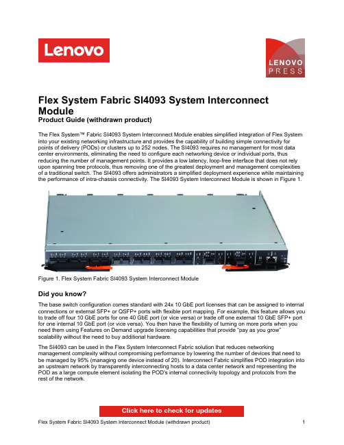
Flex System Fabric SI4093 System Interconnect ModuleProduct Guide (withdrawn product)The Flex System™ Fabric SI4093 System Interconnect Module enables simplified integration of Flex System into your existing networking infrastructure and provides the capability of building simple connectivity for points of delivery (PODs) or clusters up to 252 nodes. The SI4093 requires no management for most data center environments, eliminating the need to configure each networking device or individual ports, thus reducing the number of management points. It provides a low latency, loop-free interface that does not rely upon spanning tree protocols, thus removing one of the greatest deployment and management complexities of a traditional switch. The SI4093 offers administrators a simplified deployment experience while maintaining the performance of intra-chassis connectivity. The SI4093 System Interconnect Module is shown in Figure 1.Figure 1. Flex System Fabric SI4093 System Interconnect ModuleDid you know?The base switch configuration comes standard with 24x 10 GbE port licenses that can be assigned to internal connections or external SFP+ or QSFP+ ports with flexible port mapping. For example, this feature allows you to trade off four 10 GbE ports for one 40 GbE port (or vice versa) or trade off one external 10 GbE SFP+ port for one internal 10 GbE port (or vice versa). You then have the flexibility of turning on more ports when you need them using Features on Demand upgrade licensing capabilities that provide “pay as you grow”scalability without the need to buy additional hardware.The SI4093 can be used in the Flex System Interconnect Fabric solution that reduces networking management complexity without compromising performance by lowering the number of devices that need to be managed by 95% (managing one device instead of 20). Interconnect Fabric simplifies POD integration into an upstream network by transparently interconnecting hosts to a data center network and representing the POD as a large compute element isolating the POD's internal connectivity topology and protocols from the rest of the network.Click here to check for updatesTable 3. Supported transceivers and direct-attach cablesDescription Partnumber FeaturecodeMaximumquantitysupportedSerial console cablesFlex System Management Serial Access Cable Kit90Y9338A2RR1 SFP transceivers - 1 GbELenovo 1000BASE-T SFP Transceiver (does not support 10/100 Mbps)00FE333A5DL14 Lenovo 1000BASE-SX SFP Transceiver81Y1622326914 Lenovo 1000BASE-LX SFP Transceiver90Y9424A1PN14 SFP+ transceivers - 10 GbELenovo 10GBASE-SR SFP+ Transceiver46C3447505314 Lenovo 10GBASE-LR SFP+ Transceiver90Y9412A1PM14 Optical cables for 1 GbE SX SFP and 10 GbE SR SFP+ transceiversLenovo 1m LC-LC OM3 MMF Cable00MN502ASR614 Lenovo 3m LC-LC OM3 MMF Cable00MN505ASR714 Lenovo 5m LC-LC OM3 MMF Cable00MN508ASR814 Lenovo 10m LC-LC OM3 MMF Cable00MN511ASR914 Lenovo 15m LC-LC OM3 MMF Cable00MN514ASRA14 Lenovo 25m LC-LC OM3 MMF Cable00MN517ASRB14 Lenovo 30m LC-LC OM3 MMF Cable00MN520ASRC14 SFP+ direct-attach cables - 10 GbELenovo 1m Passive SFP+ DAC Cable90Y9427A1PH14 Lenovo 1.5m Passive SFP+ DAC Cable00AY764A51N14 Lenovo 2m Passive SFP+ DAC Cable00AY765A51P14 Lenovo 3m Passive SFP+ DAC Cable90Y9430A1PJ14 Lenovo 5m Passive SFP+ DAC Cable90Y9433A1PK14 Lenovo 7m Passive SFP+ DAC Cable00D6151A3RH14 QSFP+ transceiver and cables - 40 GbELenovo 40GBASE-SR4 QSFP+ Transceiver49Y7884A1DR2 Lenovo 40GBASE-iSR4 QSFP+ Transceiver00D9865ASTM2 Lenovo 40GBASE–eSR4 QSFP+ Transceiver00FE325A5U92 Lenovo 40GBASE-LR4 QSFP+ Transceiver00D6222A3NY2 Optical cables for 40 GbE QSFP+ SR4/iSR4/eSR4 transceiversLenovo 10m QSFP+ MTP-MTP OM3 MMF Cable90Y3519A1MM2 Lenovo 30m QSFP+ MTP-MTP OM3 MMF Cable90Y3521A1MN2 Lenovo 10m QSFP+ MTP-MTP OM3 MMF Cable (replaces 90Y3519)00VX003AT2U2 Lenovo 30m QSFP+ MTP-MTP OM3 MMF Cable (replaces 90Y3521)00VX005AT2V2 Optical breakout cables for 40 GbE QSFP+ iSR4/eSR4 transceiversLenovo 1m MTP-4xLC OM3 MMF Breakout Cable00FM412A5UA2 Lenovo 3m MTP-4xLC OM3 MMF Breakout Cable00FM413A5UB2 Lenovo 5m MTP-4xLC OM3 MMF Breakout Cable00FM414A5UC2 QSFP+ breakout cables - 40 GbE to 4x10 GbEFigure 2. Location of the I/O bays in the Flex System chassisThe SI4093 module can be installed in bays 1, 2, 3, and 4 of the Flex System chassis. A supported adapter card must be installed in the corresponding slot of the compute node. Each adapter can use up to four lanes to connect to the respective I/O module bay. The SI4093 is able to use up to three of the four lanes.Prior to Networking OS 7.8, with four-port adapters, an optional Upgrade 1 (95Y3318) was required for the SI4093s to allow communications on all four ports. With eight-port adapters, both optional Upgrade 1(95Y3318) and Upgrade 2 (95Y3320) were required for the module to allow communications on six adapter ports, and two remaining ports are not used. With Networking OS 7.8 or later, there is no need to buy additional module upgrades for 4-port and 8-port adapters if the total number of port licenses on the SI4093 does not exceed the number of external (upstream network ports) and internal (compute node network ports) connections used.In compute nodes that have an integrated dual-port 10 GbE network interface controller (NIC), NIC ports are routed to bays 1 and 2 with a specialized periscope connector, and the adapter card is not required. However, when needed, the periscope connector can be replaced with the adapter card. In this case, integrated NIC will be disabled.Table 4 shows compatibility information for the SI4093 and Flex System chassis.Table 4. Flex System chassis compatibilityDescription Partnumber EnterpriseChassis withCMMEnterpriseChassis withCMM2Carrier-gradeChassis withCMM2Flex System Fabric SI4093 System InterconnectModule95Y3313Yes Yes NoThe midplane connections between the adapters installed in the compute nodes to the switch bays in the chassis are shown diagrammatically in the following figure. The figure shows both half-wide compute nodes, such as the x240 with two adapters, and full-wide compute nodes, such as the x440 with four adapters.Figure 3. Logical layout of the interconnects between I/O adapters and I/O modulesTable 5 shows the connections between adapters installed in the compute nodes to the I/O bays in the chassis.Table 5. Adapter to I/O bay correspondenceI/O adapter slotin the compute node Port on the adapter Corresponding I/O module bay in the chassisBay 1Bay 2Bay 3Bay 4Slot 1Port 1YesPort 2YesPort 3YesPort 4YesPort 5YesPort 6YesPort 7*Port 8*Slot 2Port 1YesPort 2YesPort 3YesPort 4YesPort 5YesPort 6YesPort 7*Port 8*Slot 3(full-wide compute nodes only)Port 1YesPort 2Yes Port 3YesPort 4Yes Port 5YesPort 6Yes Port 7*Port 8*Slot 4(full-wide compute nodes only)Port 1YesPort 2Yes Port 3YesPort 4Yes Port 5YesPort 6Yes Port 7*Port 8** Ports 7 and 8 are routed to I/O bays 1 and 2 (Slot 1 and Slot 3) or 3 and 4 (Slot 2 and Slot 4), but these ports cannot be used with the SI4093.The following table lists the adapters that are supported by the I/O module.Table 6. Network adaptersDescription Part number Feature code50 Gb EthernetThinkSystem QLogic QL45212 Flex 50Gb 2-Port Ethernet Adapter7XC7A05843B2VT7XC7A05845B2VVThinkSystem QLogic QL45262 Flex 50Gb 2-Port Ethernet Adapter withiSCSI/FCoE25 Gb EthernetThinkSystem QLogic QL45214 Flex 25Gb 4-Port Ethernet Adapter7XC7A05844B2VU10 Gb EthernetEmbedded 10Gb Virtual Fabric Adapter (2-port)†None NoneFlex System CN4022 2-port 10Gb Converged Adapter88Y5920A4K3Flex System CN4052 2-port 10Gb Virtual Fabric Adapter00JY800*A5RPFlex System CN4052S 2-port 10Gb Virtual Fabric Adapter00AG540ATBTFlex System CN4052S 2-port 10Gb Virtual Fabric Adapter Advanced01CV780AU7XFlex System CN4054 10Gb Virtual Fabric Adapter (4-port)90Y3554*A1R1Flex System CN4054R 10Gb Virtual Fabric Adapter (4-port)00Y3306*A4K2Flex System CN4054S 4-port 10Gb Virtual Fabric Adapter00AG590ATBSFlex System CN4054S 4-port 10Gb Virtual Fabric Adapter Advanced01CV790AU7YFlex System CN4058S 8-port 10Gb Virtual Fabric Adapter94Y5160A4R6Flex System EN4172 2-port 10Gb Ethernet Adapter00AG530A5RN1 Gb EthernetEmbedded 1 Gb Ethernet controller (2-port)**None NoneFlex System EN2024 4-port 1Gb Ethernet Adapter49Y7900A10Y* Withdrawn from marketing† The Embedded 10Gb Virtual Fabric Adapter is built into selected compute nodes.** The Embedded 1 Gb Ethernet controller is built into selected compute nodes.The adapters are installed in slots in each compute node. Figure 4 shows the locations of the slots in the x240 Compute Node. The positions of the adapters in the other supported compute nodes are similar.Figure 4. Location of the I/O adapter slots in the Flex System x240 Compute NodeConnectors and LEDsFigure 5. Front panel of the Flex System Fabric SI4093 System Interconnect ModuleNetwork cabling requirementsThe network cables that can be used with the SI4093 module are shown in Table 7.Table 7. SI4093 network cabling requirementsTransceiver Standard Cable Connector 40 Gb Ethernet40GBASE-SR4 QSFP+ Transceiver (49Y7884)40GBASE-SR410 m or 30 m MTP fiber optics cables supplied by Lenovo(see Table 3); support for up to 100 m with OM3 multimodefiber or up to 150 m with OM4 multimode fiberMTP40GBASE-iSR4 QSFP+ Transceiver (00D9865)40GBASE-SR410 m or 30 m MTP fiber optics cables or MTP-4xLCbreakout cables up to 5 m supplied by Lenovo (see Table3); support for up to 100 m with OM3 multimode fiber or upto 150 m with OM4 multimode fiberMTP40GBASE-eSR4 QSFP+ Transceiver (00FE325)40GBASE-SR410 m or 30 m MTP fiber optics cables or MTP-4xLCbreakout cables up to 5 m supplied by Lenovo (see Table3); support for up to 300 m with OM3 multimode fiber or upto 400 m with OM4 multimode fiberMTP40GBASE-LR4 QSFP+Transceiver (00D6222)40GBASE-LR41310 nm single-mode fiber cable up to 10 km LCDirect attach cable40GBASE-CR4QSFP+ to QSFP+ DAC cables up to 7 m; QSFP+ to 4xSFP+ DAC break-out cables up to 5 m for 4x 10 GbESFP+ connections out of a 40 GbE port (see Table 3)QSFP+ 10 Gb Ethernet10GBASE-SR SFP+ Transceiver (46C3447)10GBASE-SR Up to 30 m with fiber optic cables supplied by Lenovo (seeTable 3); 850 nm OM3 multimode fiber cable up to 300 mor up to 400 m with OM4 multimode fiberLC10GBASE-LR SFP+Transceiver (90Y9412)10GBASE-LR1310 nm single-mode fiber cable up to 10 km LC Direct attach cable10GSFP+Cu SFP+ DAC cables up to 7 m (see Table 3)SFP+ 1 Gb Ethernet1000BASE-T SFPTransceiver (00FE333)1000BASE-T UTP Category 5, 5E, and 6 up to 100 meters RJ-451000BASE-SX SFP Transceiver (81Y1622)1000BASE-SX Up to 30 m with fiber optic cables supplied by Lenovo (seeTable 3); 850 nm multimode fiber cable up to 550 m (50 µ)or up to 220 m (62.5 µ)LC1000BASE-LX SFPTransceiver (90Y9424)1000BASE-LX1310 nm single-mode fiber cable up to 10 km LC Management ports1 GbE management port1000BASE-T UTP Category 5, 5E, and 6 up to 100 meters RJ-45External RS-232 management port RS-232DB-9-to-mini-USB or RJ-45-to-mini-USB console cable(comes with optional Management Serial Access Cable,90Y9338)Mini-USBWarrantyThe SI4093 carries a 1-year, customer-replaceable unit (CRU) limited warranty. When installed in a chassis, these I/O modules assume your system’s base warranty and any warranty service upgrade.Physical specificationsFigure 6. SI4093 connectivity topology - Link Aggregation Figure 7. SI4093 connectivity topology - Virtual Link AggregationFigure 8. SI4093 in the 10 GbE networkTable 8. Components that are used in 10 GbE solution with the SI4093 (Figure 8)Diagram reference Description PartnumberQuantityFlex System Virtual Fabric solutionFlex System CN4054 10Gb Virtual Fabric Adapter90Y3554 1 per compute nodeFlex System Fabric SI4093 System Interconnect Module95Y3313 2 per chassisFlex System Fabric SI4093 System Interconnect Module (Upgrade 1)*95Y3318 1 per SI4093RackSwitch G8264, G8316, or G8332* The Upgrade 1 might not be needed with flexible port mapping if the total number of the internal and external ports used on the SI4093 is less or equal to 24.Note: You also need SFP+/QSFP+ modules and optical cables or SFP+/QSFP+ DAC cables (not shown in Table 8; see Table 3 for details) for the external 10 Gb Ethernet connectivity.SI4093 in the converged FCoE networkSI4093 supports Data Center Bridging (DCB), and it can transport FCoE frames. These interconnect modules provide an inexpensive solution for transporting encapsulated FCoE packets to the Fibre Channel Forwarder (FCF), which is functioning as both an aggregation switch and an FCoE gateway. Vendor-specific examples of this scenario are shown in Figure 9, Figure 10, and Figure 11. The solution components that are used in the scenarios that are shown in Figure 9, Figure 10, and Figure 11 are listed in Table 9, Table 10, and Table 11, respectively.Figure 9. SI4093 in the FCoE network with the RackSwitch G8264CS as an FCFFigure 10. SI4093 in the FCoE network with the Brocade VDX 6730 as an FCFFigure 11. SI4093 in the FCoE network with the Cisco Nexus 5548/5596 as an FCF Table 9. SI4093 with the G8264CS as an FCF (Figure 9)Diagram reference Description PartnumberQuantityFlex System FCoE solutionFlex System CN4054 10Gb Virtual Fabric Adapter90Y3554 1 per compute node Flex System CN4054 Virtual Fabric Adapter Upgrade90Y3558 1 per VFAFlex System Fabric SI4093 System Interconnect Module95Y3313 2 per chassisFlex System Fabric SI4093 System Interconnect Module (Upgrade 1)*95Y3318 1 per SI4093RackSwitch G8264CSBrocade or Cisco MDS SAN fabricStorage systemsIBM DS3000 / DS5000IBM DS8000IBM Storwize V3700 / V5000 / V7000 / SAN Volume ControllerIBM XIV* The Upgrade 1 might not be needed with flexible port mapping if the total number of the internal and external ports used on the SI4093 is less or equal to 24.Table 10. SI4093 with the Brocade VDX 6730 as an FCF (Figure 10)Diagram reference Description PartnumberQuantityFlex System FCoE solutionFlex System CN4054 10Gb Virtual Fabric Adapter90Y3554 1 per compute nodeFlex System CN4054 Virtual Fabric Adapter Upgrade90Y3558 1 per VFAFlex System Fabric SI4093 System Interconnect Module95Y3313 2 per chassisFlex System Fabric SI4093 System Interconnect Module (Upgrade 1)*95Y3318 1 per SI4093Brocade VDX 6730 Converged SwitchBrocade SAN fabricStorage systemsDS3000 / DS5000DS8000®Storwize V3700 / V5000 / V7000 / SAN Volume ControllerXIV* The Upgrade 1 might not be needed with flexible port mapping if the total number of the internal and external ports used on the SI4093 is less or equal to 24.Table 11. SI4093 with the Cisco Nexus 5548/5596 as an FCF (Figure 11)Diagram reference Description PartnumberQuantityFlex System FCoE solutionFlex System CN4054 10Gb Virtual Fabric Adapter90Y3554 1 per compute nodeFlex System CN4054 Virtual Fabric Adapter Upgrade90Y3558 1 per VFAFlex System Fabric SI4093 System Interconnect Module95Y3313 2 per chassisFlex System Fabric SI4093 System Interconnect Module (Upgrade 1)*95Y3318 1 per SI4093Cisco Nexus 5548/5596 SwitchCisco MDS SAN fabricStorage systemsDS3500 / DS5000DS8000®Storwize V3700 / V5000 / V7000 / SAN Volume ControllerXIV* The Upgrade 1 might not be needed with flexible port mapping if the total number of the internal and external ports used on the SI4093 is less or equal to 24.Note: You also need SFP+ modules and optical cables or SFP+ DAC cables (not shown in Table 9, Table 10, and Table 11; see Table 3 for details) for the external 10 Gb Ethernet connectivity.Lenovo provides extensive FCoE testing to deliver network interoperability. For a full listing of supported FCoE and iSCSI configurations, see the System Storage Interoperation Center (SSIC) website at:/systems/support/storage/ssicFigure 12. SI4093 in the Flex System Interconnect Fabric solutionThe solution components that are used in the scenario that is shown in Figure 12 is listed in Table 12. Table 12. SI4093 in the Flex System Interconnect Fabric solution (Figure 12)Diagram reference Description PartnumberQuantityRack and PDU infrastructure42U 1200mm Deep Dynamic Rack93604PX10U 12 C19/12 C13 32A 3 Phase PDU46M414321U Quick Install Filler Panel Kit25R55592Top of Rack switchesRackSwitch G8264CS (Rear-to-Front)7309DRX23m Passive DAC SFP+ Cable90Y9430161m Passive DAC SFP+ Cable90Y942710Flex System Enterprise Chassis with SI4093 modulesFlex System Enterprise Chassis with 2x2500W PSU8721A1G3Flex System Enterprise Chassis 2500W Power Module43W904912Flex System Fabric SI4093 System Interconnect Module95Y33136Flex System Fabric SI4093 System Interconnect Module (Upgrade 1)*95Y33186Flex System Chassis Management Module68Y70303Flex System Enterprise Chassis 80mm Fan Module Pair43W90786Management application (optional)Switch Center, per install with 1 year software subscription and support for 20switches00AE2261* Upgrade 1 is required for x222 compute nodes or compute nodes with 4-port network adapters installed. Upgrade 1 is not required if 2-port LOM on the compute node other than x222 is used for network connectivity.Note: Cables or SFP+ modules for the upstream network connectivity are not included.Related publications and linksTrademarksLenovo and the Lenovo logo are trademarks or registered trademarks of Lenovo in the United States, other countries, or both. A current list of Lenovo trademarks is available on the Web athttps:///us/en/legal/copytrade/.The following terms are trademarks of Lenovo in the United States, other countries, or both:Lenovo®Flex SystemRackSwitchThinkSystem®VMready®The following terms are trademarks of other companies:Intel® is a trademark of Intel Corporation or its subsidiaries.Other company, product, or service names may be trademarks or service marks of others.。