Antennas
2158 IEEE TRANSACTIONS ON ANTENNAS AND PROP
[11] F. D’Agostino, F. Ferrara, C. Gennarelli, R. Guerriero, and G. Riccio, “An effective technique for reducing the truncation error in the nearfield-far-field trnasformation with plane-polar scanning,” Progr. Electromagn. Res., vol. 73, pp. 213–238, 1996.
[3] M. G. Cote an of bistatic electromagnetic scattering measurements by spherical near-field scanning,” in Proc. AMTA Symp., 1993, p. 191.
[13] F. Ferrara, C. Gennarelli, R. Guerriero, G. Riccio, and C. Savarese, “Extrapolation of the outside near-field data in the cylindrical scanning,” Electromagnetics, vol. 28, pp. 333–345, 2008.
ASA 3000 Active Antenna Splitter 2 x 1 8 说明书
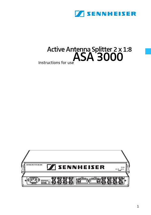
Active Antenna Splitter 2 x 1:8ASA 3000Instructions for useContentsSafety information (3)Delivery includes (3)Operating elements (4)Connection diagram (5)Trouble shooting (9)Accessories (10)Specifications (11)Manufacturer declarations (12)Brief descriptionWith the 2 x 1:8 active antenna splitter, up to eight recei-vers (EM 3031) or twin receivers (EM 3032, EM 3532) can be operated with only one pair of diversity antennas. Each diversity section is fitted with a wideband input module which can be exchanged for a selective input module. Due to the built-in antenna boosters, the signals are routed without loss the the connected receivers.The active antenna splitter allows you to make receiver systems with up to 16 channels.Areas of application:y Multi-channel RF installations (fixed or mobile)y Permanent installations in small conference centres and similar venuesSafety informationThe 2 x 1:8 active antenna splitter must only be set up and connected by an electrical engineering expert.Never open electronic units! This must only be done by authorized personnel and is all the more important for units connected to AC outlets. If units are opened by custo-mers in breach of this instruction, the warranty becomes null and void!Make sure that the air vents of the unit are not covered or blocked. Keep the unit away from central heating radiators and electric heaters!Set up the unit on an even surface or mount it into a rack! Lay the cables in such a way that no-one can stumble over them!Keep liquids and small parts which conduct electricity away from the unit! Use a damp cloth for cleaning the unit. Do not use any solvents or cleansing agents!Delivery includesy 1 active antenna splitter, 2 x 1:8y 1 mains cabley 1 rack-mounting kity 1 set of self-adhesive plastic feety 2 telescopic antennasy 1 instruction manualFor accessories, please refer to page10.Operating elements³·LED DC FEED ANT B (green)»LED POWER (red)¿Threaded holes for rack-mounting´BNC sockets for antenna outputs, diversity section “B”, B1 to B8²Exchangeable wideband input module with BNC antenna input for diversity sec-tion “B” ANT. B¶Catch for input modulesºExchangeable wideband input module with BNC antenna input for diversity sec-tion “A” ANT. A¾BNC sockets for antenna outputs, diversity section “A”, A1 to A8µIEC mains socket¸Switches DC-Feed ANT A and DC-Feed ANT B for turning the DC supply voltage for active antennas and antenna boosters on and off(switches are located inside the input module slots ² and º)Connection diagramThe below connection diagram shows the connections for an 8- or 16-channel system.Putting the unit into operationSetting up the unitThe unit is suitable for use as table top or can be mounted into a rack.̈Fix the unit to a 19" rack by using the supplied rack-mounting kit.̈To set up the unit on an even, horizontal surface, fix the four self-adhesive plastic feet to the base of the unit.Note:Some furniture surfaces have been treated with varnish, polish or synthetics which might cause stains when they come into contact with other synthetics. Despite a tho-rough testing of the synthetics used by us, we cannot rule out the possibility of discoloration, since we don’t know your furniture. To protect your furniture, we recommend placing the unit on a non-slip pad.Connecting the antennas̈You can connect the following antenna types to the BNC Array sockets ᕦ andº of the input modules:y two GZA1036 or A2003-UHF passive antennas ory two A12 active antennas ory two GZA1036 passive antennas with AB1036 antenna boosters.The ASA 3000 routes the antenna signals without loss to the respective antenna outputs.Notes:for active antennas or antenna boosters turned on. Thetwo LEDs DC FEED ANT A³ and DC FEED ANT B · lightup green.If you use passive antennas only, the DC supply voltage can be turned off. To do so, remove the two input modu-les (see “Exchanging the input modules” on page 7) andset the two switches DC-Feed ANT A and DC-Feed ANT B¸ to position “OFF”.Connecting the receiversUp to eight receivers, e.g. EM 3031, or eight twin receivers,e.g. EM 3032 or EM 3532, can be connected.̈Use BNC cables to connect the receivers to the BNC sockets ´ and ¾ as follows:First receiver:Diversity section “A” to A1, diversity section “B” to B1.Second receiver:Diversity section “A” to A2, diversity section “B” to B2.etc.Connecting the mains cablëConnect the mains cable to the IEC mains socket µ and to the mains.The ASA 3000 has no power switch. The unit is ready for operation as soon as it is connected to the mains.Note:The ASA 3000 can be connected to any mains power supply with 100V to 240V AC (50 to 60Hz).Exchanging the input modulesThe unit is fitted with two wideband input modules (470 to 870 MHz) which are suitable for most applications. Howe-ver, to ensure optimum reception reliability, we recom-mend using two selective input modules (60-MHz window)(see “Accessories” on page10).When using the selective input modules:y Make sure that all transmitters and receivers of your transmission system operate within the frequency win-dow of the selective input modules!When using the wideband input modules:y Use an active antenna (e.g. A12AD antenna) or an antenna with antenna booster (e.g. GZA 1036 antenna with AB 1036 antenna booster).To exchange the input modules:̈Use a crosstip screwdriver to loosen the screw of the Array catch for the input modules ¶.̈To remove the input modules ² and º, plug a BNC con-nector into the input modules‘ BNC sockets and pull hard (!) at the BNC connector.̈Insert the new input modules and tighten the screw ofthe catch ¶.Trouble shootingThe LED POWER » does not light upThe unit is not powered.Disturbed reception or no receptionPossible causes:y Transmitting antennas are not within the reception area Arrayy Transmitters or receivers are not turned ony Transmitter batteries are not inserted or batteries are lowy The antennas are not connected correctlyy The connecting cables are defectivey Too high cable attenuation due to too long antenna cables or wrong type of antenna cabley The selected transmission and receiving frequencies are not within the frequency window of the selective input modules (optional) and antenna boosters (optional)y When using active antennas or antenna boosters, the supply voltage must be turned on (see “Connecting the antennas” on page6). The two LEDs DC FEED ANT A³and DC FEED ANT B · light up green.If the LEDs do not light up even though the two switchesDC-Feed ANT A and DC-Feed ANT B¸ are set to position“ON”, the antenna inputs are short-circuited.AccessoriesThe following accessories are available from Sennheiser:Cat. No.A 2003 UHF Active antenna 03658 A 12 AD UHF Active antenna 04645GZA 1036Passive antenna 02243 AB 1036Antenna booster03598 IM 3000Selective input module 05241 GZL 1019 A1BNC-BNC coaxial cable, length 1 m 02324 GZL 1019 A5BNC-BNC coaxial cable, length 5 m 02325 GZL 1019 A10BNC-BNC coaxial cable, length 10 m 02326SpecificationsRF characteristics / active diversity antenna splitter Antenna splitter: 2 x 1:8, active Frequency range: 470–870MHz Distribution attenuation: +3/-1 dB Nominal impedanceof the inputs/outputs:50 ΩConnections inputs A/B:BNC sockets Connections outputsA1-A8/B1-B8:BNC sokkets Booster supply 12 V, 200 mA max. each, at the inputs A and B:short circuit-proofOverall unitSupply voltage range: nom. 100–240V AC,50–60Hz Power consumption: max. 15W Weight:approx. 3kg Dimensions: 19", 1 U Temperature range: -10 to +55 °C Selective input module (optional)Variable two-circuit bandpass filterFrequency range: 470–870 MHz Insertion loss: < 1.5 dB Bandwidth -1 dB:≥40 MHz Bandwidth -3 dB:≤60 MHz Bandwidth -10 dB:≤100 MHz Far-off selection:≥50 dB DC feed:max. 0.5 A, 20 V Input:BNC socket, 50 ΩOutput:IEC connector11Sennheiser electronic GmbH & Co. KG30900 Wedemark, GermanyPrinted in Germany Publ. 05/07 093248 / A03。
华工射频电路与天线(一)课程
Research Institute of Antennas & RF Techniques射频电路与天线(一)RF Circuits and Antennas 第1讲绪论褚庆昕华南理工大学电子与信息学院天线与射频技术研究所TEL: 22236201-601Email:qxchu@1.1RF/MW典型应用的频谱Research Institute of Antennas & RF Techniques So u thC h i n a U n i v e r s i t yo fT e c h n o l o g y 1.2RF/MW 的特点频率高¾通信系统中相对带宽Δf/f通常为一定值,所以频率f越高,越容易实现更大的带宽Δf,从而信息的容量就越大。
¾例如,对于1%的相对带宽,600MHz频率下宽带为6MHz(一个电视频道的带宽),而60GHz频率下带宽为600MHz(100个电视频道!)。
¾因此,RF/MW的一个最广泛应用就是无线通信。
Research Institute of Antennas & RF TechniquesSo u thC h i n a U n i v e r s i t yo fT e c h n o l o g y 微波接力通信Research Institute of Antennas & RF Techniques So ut hC h i n a U n i v e r s i t yo fT e c h n o l o g y 蜂窝电话系统Research Institute of Antennas & RF Techniques So u t h C h i n a U n i v e r s i t y o f T e c h n o l o g y 波长短¾天线与RF 电路的特性是与其电尺寸l /λ相关的。
ATE Corporation AS-05 Antenna Set 30 MHz to 18 GHz

Main Features•30 MHz to 18 GHz frequency range •Excellent Antenna Factor•Tripod adapter for easy vertical-horizontal polarization change •Individual calibration•Robust, rustproof aluminium construction •LightweightAS-05 is a compact size broadband Antenna System composed of a BC-01 Biconical Dipole, LP-04 Log Periodic Dipole Array and DR-01 Double Ridged horn Antenna designed for radiated emissions and immunity testing. It can be used in conjunction with any receiver or spectrum analyzer.Its ideal companion is the EMI Receiver Unit 9060 and 9180 that can be easily mounted on the antenna mast (*).(*)The direct connection between antenna and PMM Receiver Unit eliminates additional sources of uncertainties due to coaxial cable attenuation and scattering. For further information please consult our brochure “Fully CISPR-Compliant Digital EMC/EMI receivers 10 Hz to 18 GHz”.Antenna Set 30 MHz to 18 GHzProvided by: (800)404-ATECAdvanced Test Equipment Rentals®Ordering Information:AS-05 antenna set 30 MHz to 18 GHz with individual calibration reports.AS-05/TC antenna set 30 MHz to 18 GHz with typical calibration reports.Includes: BC-01 biconical antenna; LP-04 Log-periodic antenna; DR-01Double-rideged antenna; TR-01 wooden tripod; RF cable, 6 GHz, N(m)-N(m), 5 m; Soft carrying case; Rigid carrying case (for DR-01), Operating manual; Calibration reports*.* Individual calibration reports are provided with AS-05.AS-05/TC does not include individual calibration but typical antenna factor.Optional accessories:Additional TR-01 Wooden tripod extensible 60 - 180 cm with antenna mounting adapter for fast horizontal to vertical polaritazion changing. Additional RF cable, 3 GHz, N(m)-N(m), 5 m.Sales Office:Via Leonardo da Vinci, 21/2320090 Segrate (Milano) - ITALY Phone: +39 02 2699871Fax: +39 02 26998700Headquarter:Via Benessea, 29/B17035 Cisano sul Neva (SV) - ITALY Phone: +39 0182 58641Fax: +39 0182 586400E-Mail:**************************Internet: www.narda-sts.itRelated ProductsReceiversAntennasCalibrations service• 7010/00: EMI receiver 150 kHz to 1 GHz • 7010/01: EMI receiver 9 kHz to 1 GHz • 7010/03: EMI receiver 9 kHz to 3 GHz • 9010: EMI receiver 10 Hz to 30 MHz • 9010F: EMI receiver 10 Hz to 30 MHz• 9010/03P: EMI receiver 10 Hz to 300 MHz • 9010/30P: EMI receiver 10 Hz to 3 GHz • 9010/60P: EMI receiver 10 Hz to 6 GHz • 9030: EMI Receiver 30 MHz to 3 GHz • 9060: EMI Receiver 30 MHz to 6 GHz •FR-4003: Field Receiver 9 kHz to 30 MHz• LP-02: Log Periodic Antenna 200 MHz to 3 GHz • LP-03: Log Periodic Antenna 800 MHz to 6 GHz • TR-01: Antenna Tripod• VDH-01: Van der Hoofden test-head 20 kHz to 10 MHz • Antenna Set AS-02 (BC01+LP02+TR01)• Antenna Set AS-03 (BC01+LP02+LP03+TR01) • Antenna Set AS-04 (BC01+LP04+TR01)• RA01: Rod Antenna 9 kHz to 30 MHz• RA01-HV: Rod Antenna 150 kHz to 30 MHz •RA01-MIL: Rod Antenna 9 kHz to 30 MHz• Ansi 63,5 Antenna Factor • SAE ARP 958-D• Free-Space Antenna FactorSPECIFICATIONSFrequency range GainAntenna factor Max input power Connector Dimensions (L x H x W)Weight Colour Impedance ConstructionBC-0130 to 200 MHz -15 +2 dBi typical 8 to 14 dB/m typical 100 W N-female 65 x 65 x 137 cm1,8 kg RAL 703550 Ω nominal AluminiumA S 05-F E N -60801 - S p e c i fi c a t i o n s s u b j e c t t o c h a n g e s w i t h o u t p r i o r n o t i c eAS-05Antenna set 30 MHz to 18 GHzLP-04200 MHz to 6 GHz 6 dBi typical 12 to 40 dB/m typical100 W N-female 78 x 10 x 75 cm 1,1 kg RAL 703550 Ω nominal AluminiumDR-016 to 18 GHz 9 to 16 dBi typical 36 to 41 dB/m typical 150 W N-female 55 x 44 x 177 mm 0,25 kg RAL 703550 Ω nominal AluminiumBC-01 - Antenna Factor 106141822A F (d B /m )3090150210MHz MHz MHz MHz LP-04 - Antenna Factor 155253545A F (d B /m )1356GHzGHz GHz GHz DR-01 - Antenna Factor3634384042A F (d B /m )6101418GHzGHz GHz GHz。
航空专业英语
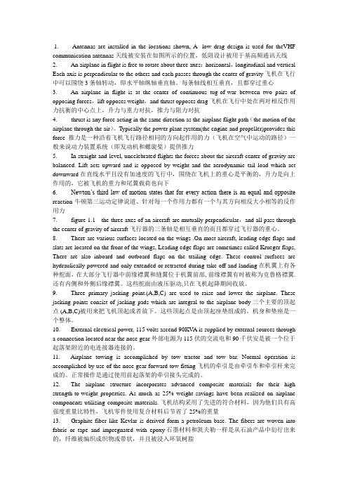
1. Antennas are installed in the locations shown, A low drag design is used for theVHF communication antennas天线被安装在如图所示的位置,低阻设计被用于基高频通讯天线2. An airplane in flight is free to rotate about three axes:horizontal,longitudinal and vertical Each axis is perpendicular to the others and each passes through the center of gravity飞机在飞行中可以围绕3条轴转动,即水平轴纵轴垂直轴。
每条轴线相互垂直,且都穿过重心3. An airplane in flight is at the center of continuous tug-of-war between two pairs of opposing forces,lift opposes weight,and thrust opposes drag飞机在飞行中处在两对相反作用力抗衡的中心点上,升力与重力对抗,推力与阻力对抗4. thrust is any force acting in the same direction as the airplane flight path(the motion of the airplane through the air)。
Typically the power plant system(the engine and propeller)provides this force推力是一种沿着飞机飞行路径相同的方向起作用的力(飞机在空气中运动的路径)一般来说动力装置系统(即发动机和螺旋桨)提供推力5. In straight-and-level, uncelebrated flights the forces about the aircraft center of gravity are balanced. Lift acts upward and is opposed by weight and the aerodynamic tail load which act downward 在直线水平且没有加速度的飞行中,围绕在飞机上的重心是平衡的,升力是向上作用的,它被飞机的重力和尾翼载荷也向下6. Newton’s third law of motion states that for every action there is an equal and opposite reaction牛顿第三运动定律说道、针对每一个作用力都有一个与其方向相反大小相等的反作用力7. figure 1.1 the three axes of an aircraft are mutually perpendicular,and all pass through the center of gravity of aircraft飞行器的三条轴是相互垂直的而且都穿过飞行器的重心。
微 带 天 线

Cavity mode: TM
E x ( x, y , z ) = −
z
π x )sin (nπ y )cos E z ( x, y, z ) = E0 sin (m a b
mnp
mode : H z ( x , y , z ) = 0
1 mπ pπ ( ) E0 cos(maπ x )sin (nbπ y )sin pdπ z h2 a d 1 π π x )cos(nπ y )sin pπ z E y ( x, y, z ) = − 2 (nbπ ) p E0 sin (m d a b d h jωε π x )cos(nπ y )cos pπ z H x ( x, y, z ) = 2 (nbπ ) E0 sin (m a b d h jωε π )E0 cos(maπ x )sin (nbπ y )cos pdπ z H y ( x, y , z ) = − 2 ( m a h
9-1
CHAPTER 9
Microstrip Antennas (PATCH ANTENNAS)
微帶天線
C. A. Balanis, Antenna Theory, Ch. 14 W. Stutzman, Antenna Theory and Design, Ch 5 (5.8) Y.-T. Lo and S.-W. Lee, Antenna Handbook, Ch. 10 Kin-Lu Wong, Design of Nonplaanar Microstrip Antennas and Transmission Lines
相位阵列天线(PhasedArrayAntenna)

自由空間中的Hertz偶極天線
6- 25
25
電磁波
第6章
天線(Antennas)
Hertz天線電磁場分析:步驟5
所求為外界之電場,該處無電流
H E= jw 0
ˆ r 1 E= jw 0 r 2 sinq r 0
ˆ rq q 0
ˆ r sinqf f r sinqH f
電磁波
第6章
天線(Antennas)
第6章 天線
6- 1
1
電磁波
第6章
天線(Antennas)
• 6-1 輻射功率場型、增益、波束(Radiation Power Pattern, Gain, and Beams) • • • • • • 6-2 Hertz偶極天線(Hertz Dipole Antenna) 6-3 遠場近似法(Far-Field Approximation) 6-4 半波長偶極天線 6-5 天線陣列(Antenna Arrays) 6-6 八木天線(Yagi-Uda Antennas) 6-7 孔口天線(Aperture Antennas)
1 I 0 ( dz )e jk0r 1 E r= cos q + 2 3 2 0 jwr v p ,0 r
I 0 (dz)e jk0r 0 k0 1 1 Eq= sinq j + 2+ 3 4 0 r r jk0 r
6- 26
26
• 6-1 輻射功率場型、增益、波束(Radiation Power Pattern, Gain, and Beams) • • • • • • 6-2 Hertz偶極天線(Hertz Dipole Antenna) 6-3 遠場近似法(Far-Field Approximation) 6-4 半波長偶極天線 6-5 天線陣列(Antenna Arrays) 6-6 八木天線(Yagi-Uda Antennas) 6-7 孔口天線(Aperture Antennas)
CommScope 296mm Profile Panel Antennas 安装说明说明书

D701-0013 Revision D, October 2016296mm Profile Panel AntennasGeneral This instruction manual contains all necessary information required to assist in the correct installation ofPanel Antennas of 296mm (11.7”) width to a 75 –115mm (3”-4.5”) diameter pipe when using themounting kit with clamp bracket. These antennas can be supplied with either fixed electrical beamdowntilt (FET), manually adjustable electrical downtilt (MET) or AISG-compatible remotely controlled electrical downtilt (RET). Mechanical downtilt is also available if required, depending on the type ofmounting kit selected.Following symbols can be found next to text outlining important information.Please follow the procedure marked with this symbol precisely.Non-compliance may lead to damage of the product.Handy tips when installing product.Unpacking Make sure that the antenna and the accessory items listed below are provided and have not beendamaged during transport.∙Antenna∙Mounting kit (mounting kit components for each configuration are shown in Figures 2 and 3).∙Hex key 6mm AF (supplied with adjustable downtilt antennas only).Mounting KitType850mm – 1200mm(33.5” –43.3”) Antennas1200mm – 1575mm(43.3” –62”) Antennas1575mm – 2700mm(62” –106.3”) AntennasFixed Downtilt F-042-GL-E F-042-GL-E F-042-GL-E MechanicalDowntiltT-045-GL-E T-041-GL-E T-029-GL-E Tilt range 0︒, 2︒ -10︒ in 1︒ steps 0︒ - 12︒ in 1︒ steps 0︒ - 8︒ in 1︒ steps MountingBracket SpacingDim A (Fig 4)716mm (28.2”)976mm (38.4”)1400mm (55.1”) Table 1: Mounting Kit Part Numbers for Different AntennasDo not install near power lines. Power lines,telephone lines, and guy wires look the same.Assume any wire or line can electrocute you.Do not install on a wet or windy day or whenlightning or thunder is in the area. Do not usemetal ladder.Wear shoes with rubber soles and heels.Wear protective clothing including along-sleeved shirt and rubber gloves.Installation Instructions∙ Ensure a torque spanner is used when tightening fasteners, see the mounting kit diagrams on the following pages for the correct torque recommendations.∙ Ensure antenna is installed with the connectors at the bottom.Assemble mounting kits as per Figure 2 and 3 of this document.1.Attach the mounting kit assembly to the antenna, before trying to clamp the brackets to the pole. 2. Downtilt angles in 1︒ increments can be obtained with the correct adjustment ofthe tilt arm bracket.∙ Downtilt can be achieved by aligning the corresponding hole in the tilt arm to the pivot bracket which mates against the mounting pole, as shown in Figure 4. The first hole is for 1︒ downtilt*, with each consecutive hole resulting in an increased inclination of 1︒.( *Note for the T-045-GL-E kit the tilt is 0︒ then 2︒ - 10︒ in 1︒ steps.)∙ For finer downtilt angle adjustments the distance in between the top and bottom mounting bracket on the pole can be adjusted.∙ For 0︒ downtilt the tilt arm may be stowed as show in Figure 4. ∙ An inclinometer or other angular measuring device may be used to verify downtilt angle as required.Figure 1: Correctly Assembled Mounting Kit Using Clamp Bracket for MechanicallyAdjustable Downtilt AntennaInstallation Instructions – Adjustable Downtilt Mounting Kit T-029-GL-E, T-041-GL-E, T-045-GL-E Upper Mounting Bracket Assembly ( To Suit Pipes OD 75-115 mm) Lower Mounting Bracket Assembly (To Suit Pipes OD 75-115 mm)Figure 2: Exploded Assembly for Upper Mounting Bracket using Clamp BracketFigure 3: Exploded Assembly for Lower Mounting Bracket using Clamp Bracket (This configuration should also be used for the upper Mounting Bracket when 0° tilt is required)Figure 4: Typical Example of Upper Bracket Placement for Various DowntiltsAOPTIONAL : THE TILT ARM AND EXTRA HARDWARECAN BE STOWED IN THE POSITION SHOWN WHEN IN 0° DOWNTILT CONFIGURATION USING A CLAMP BRACKET.Operation of AntennasFET Antennas The beam downtilt is factory set.MET Antennas The beam downtilt below the horizon is adjusted by rotating the hex socket located at the bottom of the antenna - Figure 5). Turning the hex socket in a clockwise directionincreases the beam downtilt below the horizon. Turning the hex socket in an anti-clockwise direction decreases the beam downtilt below the horizon. Beam downtiltsetting in degrees below boresight can be read off the scale at the base of the antenna.The downtilt setting is read from the face of the antenna bottom end cap at the pointwhere the scale protrudes.AISG Compliant RET Antennas AISG Compliant antennas are compatible with AISG compliant control unit equipment. For operation of downtilt using AISG compliant controllers see the controller documentation. Where manual override of RET control is provided at the antenna bottom end cap, operation is identical to that described above for MET antennas. WARNING: During downtilt adjustment ensure the hex socket is not turned past the minimum and maximum positions as shown on the downtilt indicator scale. Forcing the hex adjustment beyond this point may lead to damage of the downtilt mechanism. Using power drills and electric screwdrivers to adjust downtilt may also lead to damage of the downtilt mechanism.。
- 1、下载文档前请自行甄别文档内容的完整性,平台不提供额外的编辑、内容补充、找答案等附加服务。
- 2、"仅部分预览"的文档,不可在线预览部分如存在完整性等问题,可反馈申请退款(可完整预览的文档不适用该条件!)。
- 3、如文档侵犯您的权益,请联系客服反馈,我们会尽快为您处理(人工客服工作时间:9:00-18:30)。
Smart-802.11b MAC protocol for use with SmartAntennasHarkirat Singh and Suresh SinghEmail:{harkirat,singh}@Department of Computer SciencePortland State UniversityPortland,OR97207Abstract—Smart antennas enable a receiver to determine the Direction of Arrival(DOA)of multiple transmissions as well as to form nulls in some number of directions to maximize SINR(Signal to Interference and Noise Ratio)of the received signal.We utilize the benefits of these capabilities to develop a simple modified version of the popular802.11b protocol.This protocol exhibits high throughput under a variety of network conditions and is fair.The performance of the protocol is examined exhaustively using joint simulation in OPNET and Matlab.I.I NTRODUCTIONSmart antennas(or adaptive array antennas)have some unique properties that enable us to achieve high throughputs in ad hoc network scenarios.A transmitter equipped with a smart antenna can form a directed beam towards its receiver and a receiver can similarly form a directed beam towards the sender,thus resulting in very high gain.A receiver can also identify the direction of multiple simultaneous transmitters by running DOA algorithms and use this information to determine the directions in which it should place the nulls.Placing nulls effectively cancels out the impact of interfering transmitters.In this paper we develop a simple802.11b based MAC protocol called Smart-802.11b that explicitly uses these three properties of smart antennas(beamforming,DOA,and nulling)to achieve high throughputs.The two protocols developed in this paper are called Smart-Aloha([1],[2])and Smart-802.11b,and,as the name implies, these two protocols are modifications to the well-known Aloha and802.11b protocols.In both cases,we have added func-tionality at the MAC layer to allow it to directly control the antenna:the MAC layer controls the direction of the beam and the direction of the nulls.In addition,the antenna provides the MAC layer with DOA information for all transmissions it can hear along with signal strength information.The main results of our paper are that our protocols show a very high throughput while maintaining fairness.The conclusion is that by appropriately exploiting the benefits of smart antennas,the capacity of wireless networks can be increased dramatically. We use smart antenna model similar to our previous work [1],[2].The remainder of this paper is organized as follows. In the next section we summarizes the previous work in this and related areas.In section III we describe the two This work is funded by the NSF under grant ANIR-0125728.protocols called Smart-Aloha and Smart-802.11b.Section IVpresents our OPNET-based simulation results and we provide acomparison with the omnidirectional case.We also analyze thefairness of our protocol in section IV-C.Finally,we summarizethe main results in section V.II.L ITERATURE R EVIEWTable I presents the main throughput results of the MACprotocols designed for directional antenna equipped nodes.It isimportant to note that,most of the MAC protocols summarizedin the Table I do not fully exploit the nulling and beamformingcapabilities of the smart antenna.The salient features of our work are:1)We use realistic antenna model,we develop liner array ofantenna elements in Matlab and interface it with OPNETsimulation.2)We use nulling as well as DOA capabilities of the smartantennas.3)We do not use additional channel for the tones.4)Smart-802.11b does not use combination of omnidirec-tional/directional RTS and CTS as used by previousMAC protocols.III.D ESCRIPTION OF THE P ROTOCOLS Consider the case when a node a needs to transmit a packetto node b which is its one-hop neighbor.We assume that aknows the angular direction of b(as in[3])and it can thereforeform a beam in the direction of b.However,to maximizeSINR,b should also form a beam towards a and form nullsin the direction of all other transmitters.In order to do this,b needs to know two things–first,that a is attempting to transmit to it,and second,the angular direction of all theother transmitters that interfere at b.The two protocols wediscuss answer these two questions somewhat differently aswe describe next.A.Smart-AlohaSmart-Aloha is a slightly modified version of the standard Slotted-Aloha protocol.To transmit a packet,a transmitter forms a beam towards its receiver and begins transmission. However,it prefaces its packet transmission with the transmis-sion of a short(8-byte)pure tone(this is a simple sinusoid).Prior Work Characteristics of Maximum Throughput Simulation Expts.[3]Switched beamantenna RandomTopology Mesh Topology450beamwidth,10dB gain,250m(N=25,4hops)range for omni,900m directional MMAC DMAC802.11MMAC DMAC802.11 4CBR sources,75kbps–2Mbps each1000kbps400200800300200(5x)(2x)(1x)(4x)(1.5x)(1x) [4]Multi-beam antenna Fully connected Multi-hop(1,2,4beams each)(20nodes)(100nodes,5hops)300beamwidth,2Mbps channel1beam24124slotted(8ms slot),16Kbit packet12Mbps306060150300(Throughput converted to(Max over ROMA,UxDMA)bps from pkts/slot/net)[5]Adaptive antenna;4x4,8x84x48x8planar arrays,TDMA-802.11,1-hop(55nodes)8pkts/packet time9packets/packet time [6]Switched beam Proposed DRTS/DCTS CSMA/CA600beamwidth(50nodes)3.5Mbps 2.52[7]Circular adaptive antenna array25nodes(grid)225nodes(grid)beamwidth640,8dB gain No PC Global PC Local PC No PC Global PC Local PC(PC–Power Control)(Improvement over802.11) 1.3x 1.7x 2.1x 2.6x 4.75x 5.25x [8]Ideal adaptive antenna Protocol Beamwidth20nodes,no nulling O–Omnidirectional(20nodes,degree=7.5)D–Directional900600300100 (Improvement over omni case)ORTS/DCTS35%57%100%142%DRTS/DCTS64%107%143%186% Packet transmission is DRTS/OCTS28%43%n/a57%directional at sender/receiver ORTS/OCTS29%50%86%121%STDMA n/a400%n/a400% [9]6-element circular antenna array(No Mobility)(10fixed patterns–no adaptation)Omni Rx directional DVCS DVCS–Ideal450beamwidth,100nodes,1500m2Tx Omnidirectional Tx,Rx Directional2-ray propagation model,no nulling400kbps800kbs 1.4Mbps 2.2MbpsTABLE IS UMMARY OF D IRECTIONAL MAC PROTOCOL PERFORMANCE.a b ca because s signal at dFig.1.False beamforming.Idle nodes remain in an omni-directional mode and receive a complex sum of all such tones(note that the tones are identical for all nodes and thus we cannot identify the nodes based on the tone)and run a DOA algorithm to identify the direction and strength of the various signals.An idle node then beamforms in the direction of the maximum received signal strength and forms nulls in other directions and receives the transmitted packet.If the receiver node was the intended destination for the packet,it immediately sends an ACK using the already formed directed beam.On the other hand,if the packet was intended for some other node,then the receiver discards it.A sender waits for an ACK immediately after transmission of the packet and if it does not receive the ACK,it enters backoff in the standard way.Thus,the Smart-Aloha protocol followsa Tone/Packet/Ack sequence.The intuition behind the receiver beamforming in the direc-tion of the maximum signal is that,because of the directivity ofthe antenna,there is a high probability that it is the intendedrecipient for the packet.However,we note that in cases,asin Figure1,the receiver d incorrectly beamforms towardsa because a’s signal is stronger than b’s.While this is not a serious problem in most cases,we can envision scenarioswhere the b−→d transmission gets starved due to a largevolume of a−→c traffic.An optimization we have thereforeimplemented is a single-entry cache scheme which works asfollows:•If a node beamforms incorrectly in a given timeslot,it remembers that direction in a single-entry cache.•In the next slot,if the maximum signal strength is again in the direction recorded in the single-entry cache,then the node ignores that direction and beamforms towards the second strongest signal.–If the node receives a packet correctly(i.e.,it was the intended recipient),it does not change the cache.–If it receives a packet incorrectly,it updates the cache with this new direction.•If there is no packet in a slot from the direction recorded in the cache,the cache is reset.3This simple mechanism ensures that in cases similar to Figure 1,connections are not starved.However,we can construct more complex scenarios where a single-entry cache will fail to prevent starvation.In these cases,more sophisticated multiple-entry caching schemes are required.However,in our simula-tions,we only use the single-entry caching scheme because the probability of more complex scenarios resulting in starvation are very rare.B.Smart-802.11bThe second protocol we have developed,Smart-802.11b, is based on the802.11b standard with some changes as noted below.As in the case of the Smart-Aloha protocol,transmitters beamform towards their receivers and transmit a short sender-tone to initiate communication.However,unlike Smart-Aloha, the transmitter does not immediately follow the tone with a packet.Instead,it waits for a receiver-tone and only then transmits its packet.After transmission of a packet,it waits for the receipt of an ACK.If there is no ACK,it enters backoff as in802.11b.Figure2provides a state diagram of our tone-based protocol.The behavior of the protocol in various states can be summarized as follows:Receive receiver--tone, Send DataFig.2.State diagram of the Smart-802.11b protocol.Idle:In case a node has no packet to send,it will remain in the Idle state and set its antenna to operate in the omni-directional mode.If it receives a sender–tone from some other node,it will move into the Data Receive Wait state.On the other hand,if it wishes to send data,it will beamform in the direction of the receiver.It chooses a random number between[0..CW]and sets the CW(Contention Window)timer1.When the CW timer expires,it sends a sender–tone in the direction of the receiver and moves to the ACK Wait state.If,before the CW timer expires,the node receives a sender–tone from 1The random number selected is multiplied with20µsec.another node,it will freeze its CW timer and move to Data Receive wait state.Data Receive Wait:A node will move to this state in the event it receives a sender–tone.The node will beamform towards the sender and then randomly defer transmitting the receiver–tone by choosing a random waiting period between[0..32]×20µsec.The reason for deferring the reply is to minimize the chance of several receiver–tones colliding at the sender2.After transmitting a receiver–tone,the node remains in this state for2τ(twice the maximum propagation delay+tone transmission time).If it does not hear a transmission,it returns to the Idle state.If it hears the start of a transmission,it remains in this state and receives the packet.It then discards the packet if the packet was meant for some other node If,however,the packet was meant for it,then it sends an ACK.Ack Wait:If the sender node receives a receiver–tone before the tone RTT timer goes off(which is twice the tone transmission time plus propagation delay)it will transmit the data packet.Reception of a valid ACK will move the node to the idle state,and if packets are there in the queue then it will schedule the one at the head of the queue.The node will move to Backoff state under two conditions1)a receiver–tone did not arrive,2)an ACK was not received following transmission of the data packet.Backoff:The node computes a random Backoff interval (as in802.11)and remains in backoff for this time period (it also resets its antenna to omni-directional mode).If, however,a sender-tone is received,it freezes the backoff timer and enters the Data Receive Wait state.If the node is in backoff,upon expiration of the timer,it retransmits the sender–tone,increments the retransmit counter,and enters the ACK Wait state.A packet is discarded after the retransmit counter exceeds Max Retransmit=7,as in the IEEE802.11standard.The reception of a data packet by a node may be interfered with transmissions of sender–tones,receiver–tones,or other data packets(since our protocol does not take care of hid-den terminals).A node engaged in receiving a data packet can dynamically form nulls towards new interferers,but this process takes some time(we model this time as the length of a sender–tone).Thus,the data packet will have errors due to this interference.We combat this error by relying on FEC (Forward Error Correcting)codes as used in IEEE802.11e, where(224,208)shortened Reed Solomon(RS)codes are used.In802.11e,a MAC packet is split into blocks of208 octets and each block is separately coded using a RS encoder. A(48,32)RS code,which is also a shortened RS code,is used for the MAC header,and CRC-32is used for the Frame Check Sequence(FCS).Note that any RS block can correct up to8 octet errors.4Simulation ParametersBackground Noise +ambient Noise -143dB Propagation model Free space Bandwidth 1,000kHz Min frequency 2,402MHz Data Rate 2000kbps Carrier Sensing Threshold +3dB Minimum SINR 9dB Bit Error Based on BPSKModulation curveMaximum radio range 250m Packet Size 16KB Simulation time 200secSingle HopNumber of nodes 20Area 100x100mMultihopNumber of nodes 100Area 1500X1500TABLE IIOPNET SIMULATION PARAMETERS .IV.P ERFORMANCE S TUDYA.Simulation ModelFor our simulation,we built linear array antenna in Matlab and interfaced it with the radio pipe line stage of OPNET.We implemented Smart-Aloha into OPNET and modified the existing 802.11b implementation in OPNET to create Smart-802.11b.The modifications included adding the two-tones (sender and receiver)as well as changing the FEC to the 802.11e specification.The remainder of the simulation parameters are detailed in Table II.For every new packet that is generated at the node,a destination is chosen from the set of logical neighbors.Logical neighbors are those nodes which are within the transmission range of the radio.B.Simulation ResultsWe studied the performance of our protocol for a single-hop case with 20nodes and 5-hop case with 100nodes using of 16KB packets.We used 16antenna elements (for an effective beamwidth of 400).Figure 3plots the aggregate one-hop throughput as a function of arrival rate for the one-hop case.We note that 802.11b achieves a maximum throughput of 1Mbps while Smart-802.11b achieves a high of 8.5Mbps and Smart-Aloha achieves a high of approximately 10.5Mbps.In fact,the throughput of Smart-802.11b and Smart-Aloha increases with arrival rate because of good spatial reuse of the channel.Figure 4plots the aggregate throughput of our protocol for the 100-node 5-hop case.802.11b reaches a maximum throughput of well below 0.5Mbps while Smart-802.11b reaches a maximum of 50Mbps and Smart-Aloha reaches a maximum throughput of 60Mbps.Again,the better spatial reuse of the channel given the directivity of the antenna is the reason for this performance improvement.2Notethat our tones do not carry information about the sender and thereceiver so if all the nodes who receive a sender–tone (and are in idle state)respond immediately then the sender will detect a collision.Fig.3.Single-hop case with 20nodes.Fig.4.Five-hop case with 100nodes.C.Fairness of Smart-Aloha and Smart-802.11bWe performed a study of the fairness properties of the two new protocols and 802.11b presented here using prior work [10],[11],[12]as a guide.Since our goal was to examine the fairness of the MAC protocol (as opposed to the fairness of TCP flows),we considered the single hop flows illustrated in Figure 5.The dotted lines between two nodes in the figures indicates that the two nodes can hear one another.The arrows indicate the direction of flows and we used 2Mbit/sec CBR traffic for each flow with 512byte packets.The maximum channel capacity is also 2Mbit/sec and the remaining parameters were set as per Table II.Table III shows the data rate achieved by each flow in each of the three topologies from Figure 5.In Topology 1,nodes 1and 2are within range of one another and node 1is in fact in the second symmetric lobe formed by node 2towards node 3.In the case of Smart-802.11b,this causes node 2to5Fig.5.Topologies used for fairness study.Topology1Flow802.11b Smart-802.11b Smart-Aloha(Mbps)(Mbps)(Mbps)0−→10.6610.919 1.9572−→30.663 1.282 1.978Topology2Flow802.11b Smart-802.11b Smart-Aloha0−→10.0890.871 1.9582−→30.1080.908 1.8274−→50.5670.860 1.931Topology3Flow802.11b Smart-802.11b Smart-Aloha0−→10.4270.745 1.5732−→30.4330.914 1.4594−→50.4300.924 1.896TABLE IIIA VERAGE DATA RATES OF DIFFERENT FLOWS.sometimes incorrectly send a receiver-tone to node2resulting in lower throughput for the0−→1flow.Smart-Aloha is not affected by this because node1is closer to node0and forms a bean towards0while forming a null towards2using the DOA information.In the case of Topology2,the threeflows are equally sharing the channel because,unlike in Topology 1,the second lobe of a transmitter(such as node2)does not face unintended receivers(node1).Finally,due to the symmetry of Topology3,all theflows are equally affected by the second lobe and thus exhibit similar throughputs.In addition to the topologies discussed above,we studied other topologies including the star topology with four transmitters sending to one common receiver(as in[12]).We note that all theflows shared the channel equally in this case as well.V.C ONCLUSIONThis paper presents two simple tone-based protocols for use with smart antenna systems.These protocols do not explicitly combat hidden terminals yet they show very high throughput,exceeding that of many other protocols.We also demonstrate that our protocols share the channel fairly among multiple competingflows.In many ways our approach here is contrary to the current trend of designing increasingly complex MAC protocols for directional antenna systems.The overall conclusion is that smart antennas can indeed be used to great benefit in ad hoc networks and can enhance the performance of the popular slotted-aloha and802.11b protocols.A CKNOWLEDGMENTSWe would like to thank OPNET for their technical support.R EFERENCES[1]Harkirat Singh and Suresh Singh,“Doa-aloha:Slotted aloha for ad hocnetworking using smart antennas,”in IEEE VTC Fall’03,6–9Oct 2003.[2]Harkirat Singh and Suresh Singh,“A mac protocol based on adaptivebeamforming for ad hoc networks,”in IEEE Pimrc’03,7–10Sep2003.[3]Romit Roy Choudhury,Xue Yang,Ram Ramanathan,and Nitin H.Vaidya,“Using directional antennas for medium access control in ad hoc networks,”in ACM/SIGMOBILE MobiCom2002,23–28Sep2002.[4]Lichun Bao and J.J.Garcia-Luna-Aceves,“Transmission schedulingin ad hoc networks with directional antennas,”in ACM/SIGMOBILE MobiCom2002,23–28Sep2002.[5]S.Bellofiore,J.Foutz,indarajula,I.Bahceci,C.A.Balanis,A.S.Spanias,J.M.Capone,and T.M.Duman,“Smart antenna systemanalysis,integration,and performance for mobile ad-hoc networks (manets),”IEEE Transaction on Antennas and Propagation,vol.50, no.5,pp.571–581,May2002.[6]T.ElBatt and B.Ryu,“On the channel reservation schemes for ad hocnetworks utilizing directional antennas,”in WPMC’02,2002.[7]N.Fahmy,T.D.Todd,and V.Kezys,“Ad hoc networks with smartantennas using802.11-based protocols,”in IEEE ICC’02.[8]G.Marvin Sanchez,“Multiple access protocols with smart antennasn multihop ad hoc rural-area networks,”M.S.thesis,Royal Institute of Technology,Sweeden,Radio Communication Systems Laboratory, Department of Signals,Sensors and Sytems,June2002.[9]Rajiv Bagrodia Mineo Takai,Jay Martin and Aifeng Ren,“Directionalvirtual carrier sensing for directional antennas in mobile ad hoc net-works,”in ACM/SIGMOBILE MobiHoc2002,Oct2002.[10]T.Nandagopal,T-E.Kim,X.Gao,and V.Bharghavan,“Achieving maclayer fairness in wireless packet networks,”in ACM MOBICOM’00, August2000,pp.87–98.[11] B.Bensaou,Y.Wang,and C.C.Ko,“Fair medium access in802.11based wireless ad-hoc networks,”in ACM MOBIHOC’00,August2000, pp.99–106.[12]V.Bharghavan,A.Demers,S.Shenker,and L.Zhang,“Macaw:A mediaaccess protocol for wireless lans,”in ACM SIGCOMM’94,August1994, pp.212–225.。