HelloM3_ek-lm4f232 Schematic Rev A
MT3339
Pin Assignment and Descriptions .............................................................................................. 9 2.1 2.2 Pin assignment (top view) .................................................................................................... 9 Pin descriptions .................................................................................................................... 9
ห้องสมุดไป่ตู้
Description Update TFBGA ball map and pin description Update pin-mux and strap information Update RF part description Update System overview Update RF part electrical characteristics Update analog part electrical characteristics Update RF LDO electrical characteristics Update power scheme Add RTC domain power scheme Modify according to YC Chien’s suggestion Update by JN Yang about UART baud rate and SPI/I2C clock rate Update RF related description Update system overview by Andy Lee Update host interface related description Update power scheme Update block diagram Update crystal frequency range Update external LNA related information Update power scheme diagram and EEPROM I2C interface timing diagram Update power related description Update footprint size Change minimum input power to 2.7V Sync PIN naming of DC characteristic table and change minimum input power to 2.8V Update power scheme and RF information Update description of 32K_OUT pin Add ECLK and SYNC description Add 1.2V IO characteristic for TIMER and 32K_OUT and update serial flash size to 128Mb Remove description about factory testing and internal SRAM size Remove description about strap function tcxo on/off 1. Update RTC leakage information to typ 2. Update package dimensions information Update RF related descriptions 1. Remove Vcc description in 6.3.1 2. Add strap pin tldo_sw_sel description Change MAX of VIH for TIMER and 32K_OUT to 3.6V Change description in 5.20 about CLDO off Add RF LNA MIN of VGA gain and MAX of noise figure © 2011 MediaTek Inc. Page 2 of 37
NuMicro N9H30系列开发板用户手册说明书

NuMicro®FamilyArm® ARM926EJ-S BasedNuMaker-HMI-N9H30User ManualEvaluation Board for NuMicro® N9H30 SeriesNUMAKER-HMI-N9H30 USER MANUALThe information described in this document is the exclusive intellectual property ofNuvoton Technology Corporation and shall not be reproduced without permission from Nuvoton.Nuvoton is providing this document only for reference purposes of NuMicro microcontroller andmicroprocessor based system design. Nuvoton assumes no responsibility for errors or omissions.All data and specifications are subject to change without notice.For additional information or questions, please contact: Nuvoton Technology Corporation.Table of Contents1OVERVIEW (5)1.1Features (7)1.1.1NuMaker-N9H30 Main Board Features (7)1.1.2NuDesign-TFT-LCD7 Extension Board Features (7)1.2Supporting Resources (8)2NUMAKER-HMI-N9H30 HARDWARE CONFIGURATION (9)2.1NuMaker-N9H30 Board - Front View (9)2.2NuMaker-N9H30 Board - Rear View (14)2.3NuDesign-TFT-LCD7 - Front View (20)2.4NuDesign-TFT-LCD7 - Rear View (21)2.5NuMaker-N9H30 and NuDesign-TFT-LCD7 PCB Placement (22)3NUMAKER-N9H30 AND NUDESIGN-TFT-LCD7 SCHEMATICS (24)3.1NuMaker-N9H30 - GPIO List Circuit (24)3.2NuMaker-N9H30 - System Block Circuit (25)3.3NuMaker-N9H30 - Power Circuit (26)3.4NuMaker-N9H30 - N9H30F61IEC Circuit (27)3.5NuMaker-N9H30 - Setting, ICE, RS-232_0, Key Circuit (28)NUMAKER-HMI-N9H30 USER MANUAL3.6NuMaker-N9H30 - Memory Circuit (29)3.7NuMaker-N9H30 - I2S, I2C_0, RS-485_6 Circuit (30)3.8NuMaker-N9H30 - RS-232_2 Circuit (31)3.9NuMaker-N9H30 - LCD Circuit (32)3.10NuMaker-N9H30 - CMOS Sensor, I2C_1, CAN_0 Circuit (33)3.11NuMaker-N9H30 - RMII_0_PF Circuit (34)3.12NuMaker-N9H30 - RMII_1_PE Circuit (35)3.13NuMaker-N9H30 - USB Circuit (36)3.14NuDesign-TFT-LCD7 - TFT-LCD7 Circuit (37)4REVISION HISTORY (38)List of FiguresFigure 1-1 Front View of NuMaker-HMI-N9H30 Evaluation Board (5)Figure 1-2 Rear View of NuMaker-HMI-N9H30 Evaluation Board (6)Figure 2-1 Front View of NuMaker-N9H30 Board (9)Figure 2-2 Rear View of NuMaker-N9H30 Board (14)Figure 2-3 Front View of NuDesign-TFT-LCD7 Board (20)Figure 2-4 Rear View of NuDesign-TFT-LCD7 Board (21)Figure 2-5 Front View of NuMaker-N9H30 PCB Placement (22)Figure 2-6 Rear View of NuMaker-N9H30 PCB Placement (22)Figure 2-7 Front View of NuDesign-TFT-LCD7 PCB Placement (23)Figure 2-8 Rear View of NuDesign-TFT-LCD7 PCB Placement (23)Figure 3-1 GPIO List Circuit (24)Figure 3-2 System Block Circuit (25)Figure 3-3 Power Circuit (26)Figure 3-4 N9H30F61IEC Circuit (27)Figure 3-5 Setting, ICE, RS-232_0, Key Circuit (28)Figure 3-6 Memory Circuit (29)Figure 3-7 I2S, I2C_0, RS-486_6 Circuit (30)Figure 3-8 RS-232_2 Circuit (31)Figure 3-9 LCD Circuit (32)NUMAKER-HMI-N9H30 USER MANUAL Figure 3-10 CMOS Sensor, I2C_1, CAN_0 Circuit (33)Figure 3-11 RMII_0_PF Circuit (34)Figure 3-12 RMII_1_PE Circuit (35)Figure 3-13 USB Circuit (36)Figure 3-14 TFT-LCD7 Circuit (37)List of TablesTable 2-1 LCD Panel Combination Connector (CON8) Pin Function (11)Table 2-2 Three Sets of Indication LED Functions (12)Table 2-3 Six Sets of User SW, Key Matrix Functions (12)Table 2-4 CMOS Sensor Connector (CON10) Function (13)Table 2-5 JTAG ICE Interface (J2) Function (14)Table 2-6 Expand Port (CON7) Function (16)Table 2-7 UART0 (J3) Function (16)Table 2-8 UART2 (J6) Function (16)Table 2-9 RS-485_6 (SW6~8) Function (17)Table 2-10 Power on Setting (SW4) Function (17)Table 2-11 Power on Setting (S2) Function (17)Table 2-12 Power on Setting (S3) Function (17)Table 2-13 Power on Setting (S4) Function (17)Table 2-14 Power on Setting (S5) Function (17)Table 2-15 Power on Setting (S7/S6) Function (18)Table 2-16 Power on Setting (S9/S8) Function (18)Table 2-17 CMOS Sensor Connector (CON9) Function (19)Table 2-18 CAN_0 (SW9~10) Function (19)NUMAKER-HMI-N9H30 USER MANUAL1 OVERVIEWThe NuMaker-HMI-N9H30 is an evaluation board for GUI application development. The NuMaker-HMI-N9H30 consists of two parts: a NuMaker-N9H30 main board and a NuDesign-TFT-LCD7 extensionboard. The NuMaker-HMI-N9H30 is designed for project evaluation, prototype development andvalidation with HMI (Human Machine Interface) function.The NuMaker-HMI-N9H30 integrates touchscreen display, voice input/output, rich serial port serviceand I/O interface, providing multiple external storage methods.The NuDesign-TFT-LCD7 can be plugged into the main board via the DIN_32x2 extension connector.The NuDesign-TFT-LCD7 includes one 7” LCD which the resolution is 800x480 with RGB-24bits andembedded the 4-wires resistive type touch panel.Figure 1-1 Front View of NuMaker-HMI-N9H30 Evaluation BoardNUMAKER-HMI-N9H30 USER MANUAL Figure 1-2 Rear View of NuMaker-HMI-N9H30 Evaluation Board1.1 Features1.1.1 NuMaker-N9H30 Main Board Features●N9H30F61IEC chip: LQFP216 pin MCP package with DDR (64 MB)●SPI Flash using W25Q256JVEQ (32 MB) booting with quad mode or storage memory●NAND Flash using W29N01HVSINA (128 MB) booting or storage memory●One Micro-SD/TF card slot served either as a SD memory card for data storage or SDIO(Wi-Fi) device●Two sets of COM ports:–One DB9 RS-232 port with UART_0 used 75C3232E transceiver chip can be servedfor function debug and system development.–One DB9 RS-232 port with UART_2 used 75C3232E transceiver chip for userapplication●22 GPIO expansion ports, including seven sets of UART functions●JTAG interface provided for software development●Microphone input and Earphone/Speaker output with 24-bit stereo audio codec(NAU88C22) for I2S interfaces●Six sets of user-configurable push button keys●Three sets of LEDs for status indication●Provides SN65HVD230 transceiver chip for CAN bus communication●Provides MAX3485 transceiver chip for RS-485 device connection●One buzzer device for program applicationNUMAKER-HMI-N9H30 USER MANUAL●Two sets of RJ45 ports with Ethernet 10/100 Mbps MAC used IP101GR PHY chip●USB_0 that can be used as Device/HOST and USB_1 that can be used as HOSTsupports pen drives, keyboards, mouse and printers●Provides over-voltage and over current protection used APL3211A chip●Retain RTC battery socket for CR2032 type and ADC0 detect battery voltage●System power could be supplied by DC-5V adaptor or USB VBUS1.1.2 NuDesign-TFT-LCD7 Extension Board Features●7” resolution 800x480 4-wire resistive touch panel for 24-bits RGB888 interface●DIN_32x2 extension connector1.2 Supporting ResourcesFor sample codes and introduction about NuMaker-N9H30, please refer to N9H30 BSP:https:///products/gui-solution/gui-platform/numaker-hmi-n9h30/?group=Software&tab=2Visit NuForum for further discussion about the NuMaker-HMI-N9H30:/viewforum.php?f=31 NUMAKER-HMI-N9H30 USER MANUALNUMAKER-HMI-N9H30 USER MANUAL2 NUMAKER-HMI-N9H30 HARDWARE CONFIGURATION2.1 NuMaker-N9H30 Board - Front View Combination Connector (CON8)6 set User SWs (K1~6)3set Indication LEDs (LED1~3)Power Supply Switch (SW_POWER1)Audio Codec(U10)Microphone(M1)NAND Flash(U9)RS-232 Transceiver(U6, U12)RS-485 Transceiver(U11)CAN Transceiver (U13)Figure 2-1 Front View of NuMaker-N9H30 BoardFigure 2-1 shows the main components and connectors from the front side of NuMaker-N9H30 board. The following lists components and connectors from the front view:NuMaker-N9H30 board and NuDesign-TFT-LCD7 board combination connector (CON8). This panel connector supports 4-/5-wire resistive touch or capacitance touch panel for 24-bits RGB888 interface.Connector GPIO pin of N9H30 FunctionCON8.1 - Power 3.3VCON8.2 - Power 3.3VCON8.3 GPD7 LCD_CSCON8.4 GPH3 LCD_BLENCON8.5 GPG9 LCD_DENCON8.7 GPG7 LCD_HSYNCCON8.8 GPG6 LCD_CLKCON8.9 GPD15 LCD_D23(R7)CON8.10 GPD14 LCD_D22(R6)CON8.11 GPD13 LCD_D21(R5)CON8.12 GPD12 LCD_D20(R4)CON8.13 GPD11 LCD_D19(R3)CON8.14 GPD10 LCD_D18(R2)CON8.15 GPD9 LCD_D17(R1)CON8.16 GPD8 LCD_D16(R0)CON8.17 GPA15 LCD_D15(G7)CON8.18 GPA14 LCD_D14(G6)CON8.19 GPA13 LCD_D13(G5)CON8.20 GPA12 LCD_D12(G4)CON8.21 GPA11 LCD_D11(G3)CON8.22 GPA10 LCD_D10(G2)CON8.23 GPA9 LCD_D9(G1) NUMAKER-HMI-N9H30 USER MANUALCON8.24 GPA8 LCD_D8(G0)CON8.25 GPA7 LCD_D7(B7)CON8.26 GPA6 LCD_D6(B6)CON8.27 GPA5 LCD_D5(B5)CON8.28 GPA4 LCD_D4(B4)CON8.29 GPA3 LCD_D3(B3)CON8.30 GPA2 LCD_D2(B2)CON8.31 GPA1 LCD_D1(B1)CON8.32 GPA0 LCD_D0(B0)CON8.33 - -CON8.34 - -CON8.35 - -CON8.36 - -CON8.37 GPB2 LCD_PWMCON8.39 - VSSCON8.40 - VSSCON8.41 ADC7 XPCON8.42 ADC3 VsenCON8.43 ADC6 XMCON8.44 ADC4 YMCON8.45 - -CON8.46 ADC5 YPCON8.47 - VSSCON8.48 - VSSCON8.49 GPG0 I2C0_CCON8.50 GPG1 I2C0_DCON8.51 GPG5 TOUCH_INTCON8.52 - -CON8.53 - -CON8.54 - -CON8.55 - -NUMAKER-HMI-N9H30 USER MANUAL CON8.56 - -CON8.57 - -CON8.58 - -CON8.59 - VSSCON8.60 - VSSCON8.61 - -CON8.62 - -CON8.63 - Power 5VCON8.64 - Power 5VTable 2-1 LCD Panel Combination Connector (CON8) Pin Function●Power supply switch (SW_POWER1): System will be powered on if the SW_POWER1button is pressed●Three sets of indication LEDs:LED Color DescriptionsLED1 Red The system power will beterminated and LED1 lightingwhen the input voltage exceeds5.7V or the current exceeds 2A.LED2 Green Power normal state.LED3 Green Controlled by GPH2 pin Table 2-2 Three Sets of Indication LED Functions●Six sets of user SW, Key Matrix for user definitionKey GPIO pin of N9H30 FunctionK1 GPF10 Row0 GPB4 Col0K2 GPF10 Row0 GPB5 Col1K3 GPE15 Row1 GPB4 Col0K4 GPE15 Row1 GPB5 Col1K5 GPE14 Row2 GPB4 Col0K6GPE14 Row2GPB5 Col1 Table 2-3 Six Sets of User SW, Key Matrix Functions●NAND Flash (128 MB) with Winbond W29N01HVS1NA (U9)●Microphone (M1): Through Nuvoton NAU88C22 chip sound input●Audio CODEC chip (U10): Nuvoton NAU88C22 chip connected to N9H30 using I2Sinterface–SW6/SW7/SW8: 1-2 short for RS-485_6 function and connected to 2P terminal (CON5and J5)–SW6/SW7/SW8: 2-3 short for I2S function and connected to NAU88C22 (U10).●CMOS Sensor connector (CON10, SW9~10)–SW9~10: 1-2 short for CAN_0 function and connected to 2P terminal (CON11)–SW9~10: 2-3 short for CMOS sensor function and connected to CMOS sensorconnector (CON10)Connector GPIO pin of N9H30 FunctionCON10.1 - VSSCON10.2 - VSSNUMAKER-HMI-N9H30 USER MANUALCON10.3 - Power 3.3VCON10.4 - Power 3.3VCON10.5 - -CON10.6 - -CON10.7 GPI4 S_PCLKCON10.8 GPI3 S_CLKCON10.9 GPI8 S_D0CON10.10 GPI9 S_D1CON10.11 GPI10 S_D2CON10.12 GPI11 S_D3CON10.13 GPI12 S_D4CON10.14 GPI13 S_D5CON10.15 GPI14 S_D6CON10.16 GPI15 S_D7CON10.17 GPI6 S_VSYNCCON10.18 GPI5 S_HSYNCCON10.19 GPI0 S_PWDNNUMAKER-HMI-N9H30 USER MANUAL CON10.20 GPI7 S_nRSTCON10.21 GPG2 I2C1_CCON10.22 GPG3 I2C1_DCON10.23 - VSSCON10.24 - VSSTable 2-4 CMOS Sensor Connector (CON10) FunctionNUMAKER-HMI-N9H30 USER MANUAL2.2NuMaker-N9H30 Board - Rear View5V In (CON1)RS-232 DB9 (CON2,CON6)Expand Port (CON7)Speaker Output (J4)Earphone Output (CON4)Buzzer (BZ1)System ResetSW (SW5)SPI Flash (U7,U8)JTAG ICE (J2)Power ProtectionIC (U1)N9H30F61IEC (U5)Micro SD Slot (CON3)RJ45 (CON12, CON13)USB1 HOST (CON15)USB0 Device/Host (CON14)CAN_0 Terminal (CON11)CMOS Sensor Connector (CON9)Power On Setting(SW4, S2~S9)RS-485_6 Terminal (CON5)RTC Battery(BT1)RMII PHY (U14,U16)Figure 2-2 Rear View of NuMaker-N9H30 BoardFigure 2-2 shows the main components and connectors from the rear side of NuMaker-N9H30 board. The following lists components and connectors from the rear view:● +5V In (CON1): Power adaptor 5V input ●JTAG ICE interface (J2) ConnectorGPIO pin of N9H30Function J2.1 - Power 3.3V J2.2 GPJ4 nTRST J2.3 GPJ2 TDI J2.4 GPJ1 TMS J2.5 GPJ0 TCK J2.6 - VSS J2.7 GPJ3 TD0 J2.8-RESETTable 2-5 JTAG ICE Interface (J2) Function●SPI Flash (32 MB) with Winbond W25Q256JVEQ (U7); only one (U7 or U8) SPI Flashcan be used●System Reset (SW5): System will be reset if the SW5 button is pressed●Buzzer (BZ1): Control by GPB3 pin of N9H30●Speaker output (J4): Through the NAU88C22 chip sound output●Earphone output (CON4): Through the NAU88C22 chip sound output●Expand port for user use (CON7):Connector GPIO pin of N9H30 FunctionCON7.1 - Power 3.3VCON7.2 - Power 3.3VCON7.3 GPE12 UART3_TXDCON7.4 GPH4 UART1_TXDCON7.5 GPE13 UART3_RXDCON7.6 GPH5 UART1_RXDCON7.7 GPB0 UART5_TXDCON7.8 GPH6 UART1_RTSCON7.9 GPB1 UART5_RXDCON7.10 GPH7 UART1_CTSCON7.11 GPI1 UART7_TXDNUMAKER-HMI-N9H30 USER MANUAL CON7.12 GPH8 UART4_TXDCON7.13 GPI2 UART7_RXDCON7.14 GPH9 UART4_RXDCON7.15 - -CON7.16 GPH10 UART4_RTSCON7.17 - -CON7.18 GPH11 UART4_CTSCON7.19 - VSSCON7.20 - VSSCON7.21 GPB12 UART10_TXDCON7.22 GPH12 UART8_TXDCON7.23 GPB13 UART10_RXDCON7.24 GPH13 UART8_RXDCON7.25 GPB14 UART10_RTSCON7.26 GPH14 UART8_RTSCON7.27 GPB15 UART10_CTSCON7.28 GPH15 UART8_CTSCON7.29 - Power 5VCON7.30 - Power 5VTable 2-6 Expand Port (CON7) Function●UART0 selection (CON2, J3):–RS-232_0 function and connected to DB9 female (CON2) for debug message output.–GPE0/GPE1 connected to 2P terminal (J3).Connector GPIO pin of N9H30 Function J3.1 GPE1 UART0_RXDJ3.2 GPE0 UART0_TXDTable 2-7 UART0 (J3) Function●UART2 selection (CON6, J6):–RS-232_2 function and connected to DB9 female (CON6) for debug message output –GPF11~14 connected to 4P terminal (J6)Connector GPIO pin of N9H30 Function J6.1 GPF11 UART2_TXDJ6.2 GPF12 UART2_RXDJ6.3 GPF13 UART2_RTSJ6.4 GPF14 UART2_CTSTable 2-8 UART2 (J6) Function●RS-485_6 selection (CON5, J5, SW6~8):–SW6~8: 1-2 short for RS-485_6 function and connected to 2P terminal (CON5 and J5) –SW6~8: 2-3 short for I2S function and connected to NAU88C22 (U10)Connector GPIO pin of N9H30 FunctionSW6:1-2 shortGPG11 RS-485_6_DISW6:2-3 short I2S_DOSW7:1-2 shortGPG12 RS-485_6_ROSW7:2-3 short I2S_DISW8:1-2 shortGPG13 RS-485_6_ENBSW8:2-3 short I2S_BCLKNUMAKER-HMI-N9H30 USER MANUALTable 2-9 RS-485_6 (SW6~8) FunctionPower on setting (SW4, S2~9).SW State FunctionSW4.2/SW4.1 ON/ON Boot from USB SW4.2/SW4.1 ON/OFF Boot from eMMC SW4.2/SW4.1 OFF/ON Boot from NAND Flash SW4.2/SW4.1 OFF/OFF Boot from SPI Flash Table 2-10 Power on Setting (SW4) FunctionSW State FunctionS2 Short System clock from 12MHzcrystalS2 Open System clock from UPLL output Table 2-11 Power on Setting (S2) FunctionSW State FunctionS3 Short Watchdog Timer OFFS3 Open Watchdog Timer ON Table 2-12 Power on Setting (S3) FunctionSW State FunctionS4 Short GPJ[4:0] used as GPIO pinS4Open GPJ[4:0] used as JTAG ICEinterfaceTable 2-13 Power on Setting (S4) FunctionSW State FunctionS5 Short UART0 debug message ONS5 Open UART0 debug message OFFTable 2-14 Power on Setting (S5) FunctionSW State FunctionS7/S6 Short/Short NAND Flash page size 2KBS7/S6 Short/Open NAND Flash page size 4KBS7/S6 Open/Short NAND Flash page size 8KBNUMAKER-HMI-N9H30 USER MANUALS7/S6 Open/Open IgnoreTable 2-15 Power on Setting (S7/S6) FunctionSW State FunctionS9/S8 Short/Short NAND Flash ECC type BCH T12S9/S8 Short/Open NAND Flash ECC type BCH T15S9/S8 Open/Short NAND Flash ECC type BCH T24S9/S8 Open/Open IgnoreTable 2-16 Power on Setting (S9/S8) FunctionCMOS Sensor connector (CON9, SW9~10)–SW9~10: 1-2 short for CAN_0 function and connected to 2P terminal (CON11).–SW9~10: 2-3 short for CMOS sensor function and connected to CMOS sensorconnector (CON9).Connector GPIO pin of N9H30 FunctionCON9.1 - VSSCON9.2 - VSSCON9.3 - Power 3.3VCON9.4 - Power 3.3V NUMAKER-HMI-N9H30 USER MANUALCON9.5 - -CON9.6 - -CON9.7 GPI4 S_PCLKCON9.8 GPI3 S_CLKCON9.9 GPI8 S_D0CON9.10 GPI9 S_D1CON9.11 GPI10 S_D2CON9.12 GPI11 S_D3CON9.13 GPI12 S_D4CON9.14 GPI13 S_D5CON9.15 GPI14 S_D6CON9.16 GPI15 S_D7CON9.17 GPI6 S_VSYNCCON9.18 GPI5 S_HSYNCCON9.19 GPI0 S_PWDNCON9.20 GPI7 S_nRSTCON9.21 GPG2 I2C1_CCON9.22 GPG3 I2C1_DCON9.23 - VSSCON9.24 - VSSTable 2-17 CMOS Sensor Connector (CON9) Function●CAN_0 Selection (CON11, SW9~10):–SW9~10: 1-2 short for CAN_0 function and connected to 2P terminal (CON11) –SW9~10: 2-3 short for CMOS sensor function and connected to CMOS sensor connector (CON9, CON10)SW GPIO pin of N9H30 FunctionSW9:1-2 shortGPI3 CAN_0_RXDSW9:2-3 short S_CLKSW10:1-2 shortGPI4 CAN_0_TXDSW10:2-3 short S_PCLKTable 2-18 CAN_0 (SW9~10) Function●USB0 Device/HOST Micro-AB connector (CON14), where CON14 pin4 ID=1 is Device,ID=0 is HOST●USB1 for USB HOST with Type-A connector (CON15)●RJ45_0 connector with LED indicator (CON12), RMII PHY with IP101GR (U14)●RJ45_1 connector with LED indicator (CON13), RMII PHY with IP101GR (U16)●Micro-SD/TF card slot (CON3)●SOC CPU: Nuvoton N9H30F61IEC (U5)●Battery power for RTC 3.3V powered (BT1, J1), can detect voltage by ADC0●RTC power has 3 sources:–Share with 3.3V I/O power–Battery socket for CR2032 (BT1)–External connector (J1)●Board version 2.1NUMAKER-HMI-N9H30 USER MANUAL2.3 NuDesign-TFT-LCD7 -Front ViewFigure 2-3 Front View of NuDesign-TFT-LCD7 BoardFigure 2-3 shows the main components and connectors from the Front side of NuDesign-TFT-LCD7board.7” resolution 800x480 4-W resistive touch panel for 24-bits RGB888 interface2.4 NuDesign-TFT-LCD7 -Rear ViewFigure 2-4 Rear View of NuDesign-TFT-LCD7 BoardFigure 2-4 shows the main components and connectors from the rear side of NuDesign-TFT-LCD7board.NuMaker-N9H30 and NuDesign-TFT-LCD7 combination connector (CON1).NUMAKER-HMI-N9H30 USER MANUAL 2.5 NuMaker-N9H30 and NuDesign-TFT-LCD7 PCB PlacementFigure 2-5 Front View of NuMaker-N9H30 PCB PlacementFigure 2-6 Rear View of NuMaker-N9H30 PCB PlacementNUMAKER-HMI-N9H30 USER MANUALFigure 2-7 Front View of NuDesign-TFT-LCD7 PCB PlacementFigure 2-8 Rear View of NuDesign-TFT-LCD7 PCB Placement3 NUMAKER-N9H30 AND NUDESIGN-TFT-LCD7 SCHEMATICS3.1 NuMaker-N9H30 - GPIO List CircuitFigure 3-1 shows the N9H30F61IEC GPIO list circuit.Figure 3-1 GPIO List Circuit NUMAKER-HMI-N9H30 USER MANUAL3.2 NuMaker-N9H30 - System Block CircuitFigure 3-2 shows the System Block Circuit.NUMAKER-HMI-N9H30 USER MANUALFigure 3-2 System Block Circuit3.3 NuMaker-N9H30 - Power CircuitFigure 3-3 shows the Power Circuit.NUMAKER-HMI-N9H30 USER MANUALFigure 3-3 Power Circuit3.4 NuMaker-N9H30 - N9H30F61IEC CircuitFigure 3-4 shows the N9H30F61IEC Circuit.Figure 3-4 N9H30F61IEC CircuitNUMAKER-HMI-N9H30 USER MANUAL3.5 NuMaker-N9H30 - Setting, ICE, RS-232_0, Key CircuitFigure 3-5 shows the Setting, ICE, RS-232_0, Key Circuit.NUMAKER-HMI-N9H30 USER MANUALFigure 3-5 Setting, ICE, RS-232_0, Key Circuit3.6 NuMaker-N9H30 - Memory CircuitFigure 3-6 shows the Memory Circuit.NUMAKER-HMI-N9H30 USER MANUALFigure 3-6 Memory Circuit3.7 NuMaker-N9H30 - I2S, I2C_0, RS-485_6 CircuitFigure 3-7 shows the I2S, I2C_0, RS-486_6 Circuit.NUMAKER-HMI-N9H30 USER MANUALFigure 3-7 I2S, I2C_0, RS-486_6 Circuit3.8 NuMaker-N9H30 - RS-232_2 CircuitFigure 3-8 shows the RS-232_2 Circuit.NUMAKER-HMI-N9H30 USER MANUALFigure 3-8 RS-232_2 Circuit3.9 NuMaker-N9H30 - LCD CircuitFigure 3-9 shows the LCD Circuit.NUMAKER-HMI-N9H30 USER MANUALFigure 3-9 LCD Circuit3.10 NuMaker-N9H30 - CMOS Sensor, I2C_1, CAN_0 CircuitFigure 3-10 shows the CMOS Sensor,I2C_1, CAN_0 Circuit.NUMAKER-HMI-N9H30 USER MANUALFigure 3-10 CMOS Sensor, I2C_1, CAN_0 Circuit3.11 NuMaker-N9H30 - RMII_0_PF CircuitFigure 3-11 shows the RMII_0_RF Circuit.NUMAKER-HMI-N9H30 USER MANUALFigure 3-11 RMII_0_PF Circuit3.12 NuMaker-N9H30 - RMII_1_PE CircuitFigure 3-12 shows the RMII_1_PE Circuit.NUMAKER-HMI-N9H30 USER MANUALFigure 3-12 RMII_1_PE Circuit3.13 NuMaker-N9H30 - USB CircuitFigure 3-13 shows the USB Circuit.NUMAKER-HMI-N9H30 USER MANUALFigure 3-13 USB Circuit3.14 NuDesign-TFT-LCD7 - TFT-LCD7 CircuitFigure 3-14 shows the TFT-LCD7 Circuit.Figure 3-14 TFT-LCD7 CircuitNUMAKER-HMI-N9H30 USER MANUAL4 REVISION HISTORYDate Revision Description2022.03.24 1.00 Initial version NUMAKER-HMI-N9H30 USER MANUALNUMAKER-HMI-N9H30 USER MANUALImportant NoticeNuvoton Products are neither intended nor warranted for usage in systems or equipment, anymalfunction or failure of which may cause loss of human life, bodily injury or severe propertydamage. Such applications are deemed, “Insecure Usage”.Insecure usage includes, but is not limited to: equipment for surgical implementation, atomicenergy control instruments, airplane or spaceship instruments, the control or operation ofdynamic, brake or safety systems designed for vehicular use, traffic signal instruments, all typesof safety devices, and other applications intended to support or sustain life.All Insecure Usage shall be made at customer’s risk, and in the event that third parties lay claimsto Nuvoton as a result of customer’s Insecure Usage, custome r shall indemnify the damagesand liabilities thus incurred by Nuvoton.。
EKI-LM4F232中文资料(ti)中文数据手册「EasyDatasheet - 矽搜」

TI的产品或服务与陈述的或超越TI针对该产品或服务的空隙所有的快递和相关TI产品或服务的任何默示担保规定的参数不同的转售,是一种不公平和欺诈性商业行 为. TI是不负责或承担任何此类陈述.
其硬件产品的TI保证产品性能在销售时根据TI的标准保修时间的规范.测试和其它质量控制方法仅适用,且TI认为有必要支持这项保证.除非政府强制要求 ,否则没有必要对每种产品的所有参数进行测试.
TI对应用帮助或客户产品设计不承担任何责任.客户负责他们的产品和应用中使用TI组件.为了尽量减少与客户产品和应用相关的风险,客户应提供 充分的设计与操作安全措施.
描写
Stellaris LM4F232评估套件 凯尔的RealView® MDK-ARM(32 KB
代码大小限制)
Stellaris LM4F232评估套件
IAR Systems的嵌入式工作台
Байду номын сангаас
®
(32 KB的代码大小限制)
Stellaris LM4F232评估套件 Sourcery Codebench完成(30天有限)
TI不声明或保证任何许可,明示或暗示的,是任何TI专利权,版权,口罩工作的权利,或其他TI知识产权有关的任何组合,机器或过程中授予在TI产品或服务被使用 .有关第三方的产品或服务通过TI发布的信息不会从TI构成许可使用这种产品或服务或保证或认可.要使用这些信息可能需要获得的专利或第三方,或是从TI获得关 于TI专利或其他知识产权的许可的其他知识产权的第三方许可证.
ROHM BD34301EKV 32位D A转换器IC说明书

32bit D/A Converter I C ‘BD34301EKV’for Hi-Fi Audio EquipmentApril 1, 2021ROHM Co., Ltd.Marketing Communications Dept.*MUS-IC TM is a trademark or registered trademark of ROHM Co., Ltd.*Please note that this document is current as of the date of publicationROHM's first, most advanced MUS-IC TM series DAC chip enablesexpressive playback of classical musicAudio SoCSpeakersHigh Fidelity Audio Equipment and ROHM’s ApproachRadio/TV TunerRecording Media (Audio Source)Power Supply ICReleased Sep 2017We are developing a variety of products for high-fidelity audio equipmentAnalog Signal Digital Signal Control SignalMedia DecoderAmplifierAnalog DesignAudio DeviceSound Processor (Digital)MCUD/A ConverterSound Processor (Analog)Sound ProcessorReleased Oct 2016AmplifierReleased Mar 2018Digital DesignSpeakersClass D Speaker AmplifierClass AB Speaker AmpSupports high-fidelity, high-res audioSupports high-res audioSupports high-fidelity, high-res audio Supports high-fidelity, high-res audio12345Listening Evaluation ResultsConventional New ProductClarityRealityExpansionResolutionLocalizationBass feeling stereotacticDistortion feelingPowerfulnessAchieving Optimum Sound Quality Using ROHM’s Vertically Integrated Production System and Sound Quality Design TechnologyIC Layout, PhotomaskManufacturingWafer Formation ProcessDie and Lead FrameFinished IC ChipROHM’s Vertically Integrated Production SystemThe parameters in each process confirmedto have an effect on sound quality are shown belowLead FrameIC LayoutBonding WirePackageAt various steps in our vertically integrated production process, we have identified 28 parametersthat affect sound quality and adjusted them one by one to create the desired soundEx) Sound Processors for Hi-Fi AudioPlayer (Audio Source)PlayerPreamp (Volume Control)Sound ProcessorMain AmpPower AmpSpeakersIntegrated AmpMaintains information even at low volumeCheck sound quality through actual listening evaluation basedon a set of indicatorsPackageCircuit Design12 parameters6 parameters6 parameters1 parameter3 parametersVerify the sound quality in a dedicated listening room (At the Yokohama Technology Center)ROHM’s High -End Audio Device Brand: ROHM Musical Device [MUS-IC]For more information, please visit ROHM’s Musical Device ‘MUS -IC TM ’ web page.https:///mus-ic/MUS-IC TMCreated by combining the ‘Sound Quality Design Technology ’with ROHM’s corporate mission of ‘Quality First ’, ‘Vertically Integrated Production System ’, and ‘Contribution to the Musical Culture ’, MUS-IC TM (official name: ROHM Musical Device‘MUS -IC TM ’) is an audio device brand that represents the ultimate IC solutions developed by ROHM’s team of experienced and dedicated engineers.Quality FirstQ ualityContributing to Music CultureF or everyonemoved by musicSound QualityDesign TechnologyS oundVertically Integrated Production SystemC raftsmanshipDevelopment ConceptMUS-IC TMProduct OverviewROHM's first top-shelf MUS-IC TM series of DAC chips enables expressive playback of classical musicKey CharacteristicsNo. of Outputs: 2ch (stereo)Resolution: 32bitSampling Frequency: 32kHz to 768kHzS/N Ratio: 130dB (typ.)THD+N: -115dB (typ.)DSD Clock: 2.8MHz, 5.6MHz,11.2MHz, 22.4 MHzFIR Filter: Preset, Custom, External Segment We will begin selling the BD34301EKV DAC chip along with an evaluationBD34301EKV-EVK-001 Evaluation BoardEnables immediateevaluation of the soundquality of the BD34301EKV Please refer to the evaluation board user’s guide for details.The BD34301EKV delivers superior performance in audio equipment by improving sound quality in ways that cannotbe defined by numerical characteristicsDeliver sound quality characteristics that allow one to hear elementssuch as ‘spatial reverberation’, ‘quietness’, and ‘dynamic range’D/A Conversion Circuit⚫Minimizes the power supplyimpedance of each current segment ⚫Optimized wiring layout⇒Reduces the clock delay (thatdetermines the timing operation of each current segment) as much as possibleDigital Signal Processing Circuit⚫The FIR filter (a key function) isdesigned to faithfully process even the smallest signals⇒Achieves a rejection band attenuation (a filter performance index) of -150dB or lessEfforts to improve sound quality performanceBD34301EKV MUS-IC TM 32bit D/A Converter ICFeature 1: Achieves best-in-class sound quality characteristics ideal for classical musicFeature 2: Customizable digital filter allows designers to tailor the sound to audio equipment The BD34301EKV includes a customizable digital filter -a key feature of the digital signal processing circuit -supporting the creation of the ideal sound sought by audio equipmentmanufacturersFIR Filter Specifications⚫Select from preset / custom / external settings⚫The filter’s calculation coefficients and oversampling rate can alsobe customized with the program function⇒Configure unique digital filters to easily achieve different sound qualitytunings for each audio deviceCustomizable digital filters help reduce development loadand create the ideal sound sought by manufacturersReduce the power supply wiring impedance of each currentsegment as much as possibleSound quality improvement effect: Improved bass power and depth,resulting in better sound range balanceEliminating the common impedance from each current segment to the power supply pin makes it possible to align the matching characteristics of the current segments-120-110-100-90-80-70-60-50-40-30-20-100-100-90-80-70-60-50-40-30-20-10T H D +N (d B )Input Level (dBFS)THD+N vs Input LevelBD34301EKVWiring ImpedanceCurrent SegmentCurrent Segment Current SegmentMinimize clock skew and optimize slew rateSound quality improvement effect: Increased realism and resolution alongwith bassClockCurrent SegmentCurrent SegmentCurrent SegmentCurrent Segment time Level (L→H)Fastest ClockClock WaveformSlowest ClockMinimize clock skew between current segmentsMaterial of bonding wires connecting the chip to the lead frameMinimize stress on chips in IC packagesAu CuSound improvement effect: More natural reverberation , with a more delicateinstrumental toneSelect the best bonding wires material for the device because its material that connecting the device to the lead frame is affected the sound qualityBonding WireSelect the IC package and wafer processing method that minimize stress . At the same time, adopt a completelysymmetrical chip layout for the current segment circuit.Sound improvement effect: Reduced sound peculiarities, resulting in amore natural soundCurrent OutputPins Current OutputPinsChipIC PackageCompletely symmetricalLch Rch 電流セグメントLchRchCurrent Segment Examples of Sound Quality Improvement Effects Based on Sound Quality Design Tech.P . 10© 2021 ROHM Co., Ltd. Sales InformationThe BD34301EKV enables evaluation and adoption for a wide range of customerMUS-IC TM Sales⚫Supporting documents required for evaluation are now available on ROHM’s website:https:///products/audio-video/audio-converters/audio-dacs/bd34301ekv-product/documents⚫An evaluation board (BD34301EKV-EVK-001) is also available together with IC through online distributors Part No: BD34301EKVSales Launch Date: From December 2020Reference Price:$80.5 /pc. (excluding tax)Production Status: In mass production Evaluation Board Sales Part No: BD34301EKV-EVK-001Sales Launch Date: From February 2021Reference Price: Please refer to each online distributor websitePlease consider the BD34301EKV MUS-IC TM 32bit D/A converter IC for your next design Electronic Components and Parts Search | DigiKey ElectronicsSearch results for: bd34301ekv ROHM Semiconductor –Mouserbd34301ekv -Search Results | Farnell DE© 2021 ROHM Co., Ltd.Notes•The content specified herein is for the purpose of introducing ROHM’s products (hereinafter “Products”).•If you wish to use any such Product, please be sure to refer to the specifications, which can be obtained from ROHM upon request.•Great care was taken in ensuring the accuracy of the information specified in this document. However, should you incur any damage arising from any inaccuracy or misprint of such information, ROHM shall bear no responsibility for such damage.•The technical information specified herein is intended only to show the typical functions of and examples of application circuits for the Products.•ROHM does not grant you, explicitly or implicitly, any license to use or exercise intellectual property or other rights held by ROHM and other parties.•ROHM shall bear no responsibility whatsoever for any dispute arising from the use of such technical information.•If you intend to export or ship overseas any Product or technology specified herein that may be controlled under the Foreign Exchange and the Foreign Trade Law, you will be required to obtain a license or permit under the Law.•The content specified in this document is correct as of April 2021.© 2021 ROHM Co., Ltd.P. 12。
22-SCM-232序列转换模块固件v2.004释放说明书

Release Note 22-SCM-232 Serial Converter Module Firmware v2.004This release note describes major revision 2, minor revision 4 of firmware for the 22-SCM-232 converter.IntroductionThe following information is included in this document: EnhancementsThis section describes the enhancement provided in this revision of firmware:•The Diamond LED now flashes red to indicate that a PCCC (Programmable Controller Communications Command) control timeout has occurred, and will continue flashing red until it receives another DF1 message.Corrected AnomaliesThis section describes the anomaly corrected in this revision of firmware:•Corrects the way the 22-SCM-232 module flash updates a 22-COMM-E communication adapter that previously would cause the module to intermittently fail.For information about:See page:Enhancements 1Corrected Anomalies 1Determining Firmware Revision 2Firmware Flashing 4Restrictions 6Compatible Revisions 6Rockwell Automation Support 7Product Satisfaction Return 7222-SCM-232 Serial Converter Module Firmware v2.004Determining Firmware Revision This section describes procedures to determine the firmware revision of your 22-SCM-232 converter.Using the External LCD HIM (22-HIM-**)22-SCM-232 Serial Converter Module Firmware v2.0043Using DriveExplorer Lite/Fullunch DriveExplorer and go online with the drive that is connected tothe 22-SCM-232 converter.2.In the DriveExplorer treeview, click on 22-SCM-232 Serial Module asshown in Figure 1.3.Click the information icon to display the converter’s properties screen.4.The “Revision:” field shows the present revision (for example, 2.003) ofthe converter firmware.Figure 1 Information Icon in DriveExplorer WindowTIP: When clicking on the 22-SCM-232 converter using version 5.01 orhigher DriveExplorer Lite/Full, the converter firmware revision is alsoshown in the right pane of the DriveExplorer window.Step 4422-SCM-232 Serial Converter Module Firmware v2.004Using DriveExecutiveunch DriveExecutive and go online with the drive that is connected tothe 22-SCM-232 converter.2.In the DriveExecutive treeview, click on 22-SCM-232 as shown inFigure 2.3.Click the information icon to display the converter’s Properties screen.4.The “Revision:” field shows the present revision (for example, 2.003) ofthe converter firmware.Figure 2 Information Icon in DriveExecutive WindowFirmware FlashingThis section describes procedures to flash upgrade your converter firmware. Flash kits for drives, communications adapters, and peripherals are provided on the Allen-Bradley Web Updates site located at / support/abdrives/webupdate.Step 4ATTENTION: Risk of permanent equipment damage exists. Once a flash update has been started, do not remove power from the drive until after the download has completed and the Diamond LED status indicator on the22-SCM-232 becomes FLASHING GREEN. If power is removed before this occurs, the 22-SCM-232 may be permanently damaged. A22-SCM-232 that has been damaged in this way cannot be repaired.22-SCM-232 Serial Converter Module Firmware v2.0045Installing the Flash Kit1.Install the flash kit utility from the Allen-Bradley Web Updates site forthe 22-SCM-232 converter. (This also automatically installs the latest version of the ControlFLASH utility on your computer.)2.You are now ready to use DriveExplorer, DriveExecutive orControlFLASH to update the converter. Follow the instructions in the appropriate section below.Using DriveExplorer Lite/Full1.With the Flash Kit installed (see Installing the Flash Kit), launchDriveExplorer and go online with the drive that is connected to the22-SCM-232 converter.2.In the DriveExplorer treeview, click on 22-SCM-232 Serial Module.Then click the information icon as shown in Figure 1 to display theconverter’s properties screen.3.On the 22-SCM-232 properties screen, click the Details tab.Important:This update may cause the 22-SCM-232 parameters to revert to their default values. You may want to save yourconfiguration using DriveExplorer or the HIM CopyCatfeature before upgrading.4.To start the flash update, click the Flash Update… button. Follow thescreen prompts until the flash update procedure completes and displays the new firmware revision (v2.004).Using DriveExecutive1.With the Flash Kit installed (see Installing the Flash Kit), launchDriveExecutive and go online with the drive that is connected to the 22-SCM-232 converter.2.In the DriveExecutive treeview, click on 22-SCM-232. Then click theinformation icon as shown in Figure 2 to display the converter’sProperties screen.3.On the 22-SCM-232 Properties screen, click the Component Details tab.Important:This update may cause the 22-SCM-232 parameters to revert to their default values. You may want to save yourconfiguration using DriveExecutive or the HIM CopyCatfeature before upgrading.4.To start the flash update, click the Flash Update button. Follow thescreen prompts until the flash update procedure completes and displays the new firmware revision (v2.004).622-SCM-232 Serial Converter Module Firmware v2.004Using ControlFLASH1.With the Flash Kit installed (see Installing the Flash Kit on page5),launch ControlFLASH by selecting Start > (All) Programs > FlashProgramming Tools > ControlFLASH.2.Choose the 22-SCM-232 v2.004 update from the list of availableupdates.Important:This update may cause the 22-SCM-232 parameters to revertto their default values. You may want to save yourconfiguration using the HIM CopyCat feature,DriveExplorer or DriveExecutive before upgrading.3.Follow the screen prompts until the flash procedure completes anddisplays the new firmware revision (v2.004).Restrictions No restrictions apply to this revision of firmware.Compatible Revisions To use this revision of firmware, update your system tools as follows:Update this:To this version or later:DriveExplorer Lite/Full 4.01DriveExecutive 3.01PowerFlex 4-Class Drive all versions compatibleExternal LCD HIM (22-HIM-**)all versions compatibleRSLinx Classic 2.4322-SCM-232 Serial Converter Module Firmware v2.0047Rockwell AutomationSupportRockwell Automation provides technical information on the web to assist you in using our products. At , you can find technical manuals, a knowledge base of Frequently Asked Questions (FAQs), technical and application notes, sample code and links to software service packs, and a MySupport feature that you can customize to make the best use of these tools.Rockwell Automation also provides complimentary phone support for drives, communication adapters, and peripherals. If you experience a problem with the 22-SCM-232 converter, please review the information in its User Manual. For further help in getting your converter operational, contact a Customer Support representative: For an additional level of technical phone support for installation, configuration and troubleshooting, we offer TechConnect Support programs. For more information, contact your local distributor or Rockwell Automation representative, or visit . Product Satisfaction Return Rockwell Automation tests all products to ensure that they are fully operational when shipped from the manufacturing facility. However, if your product is not functioning and needs to be returned: United States (1) 262.512.8176Monday – Friday, 7am – 6pm CST Outside United States Please contact your local Rockwell Automation representative for any technical support issues.United States Contact your distributor. You must provide a Customer Support case number (see phone number above to obtain one) to your distributor to complete the return process.Outside United States Please contact your local Rockwell Automation representative for return procedure.U.S.Allen-BradleyDrivesTechnicalSupport-Tel:(1)262.512.8176,Fax:(1)262.512.2222,Email:*****************,Online:/support/abdrivesPublication 22SCM-RN001A-EN-P – June, 2006Copyright © 2006 Rockwell Automation, Inc. All rights reserved. Printed in USA.。
斑马技术公司DS8108数字扫描仪产品参考指南说明书

Atmel 2322I 可编程串行存储器数据手册说明书
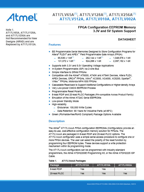
Features●EE Programmable Serial Memories Designed to Store Configuration Programs forAltera ® FLEX ® and APEX ™ Field Programmable Gate Arrays (FPGA)●Supports both 3.3V and 5.0V Operating Voltage Applications ●In-System Programmable (ISP) via 2-wire Bus ●Simple Interface to SRAM FPGAs●Compatible with the Atmel ® AT6000, AT40K and AT94K Devices, Altera FLEX,APEX Devices, ORCA ® FPGAs, Xilinx ® XC3000, XC4000, XC5200, Spartan ®, Virtex ™ FPGAs, Motorola MPA1000 FPGAs●Cascadable Read-back to Support Additional Configurations or Higher-density Arrays ●Very Low-power CMOS EEPROM Process ●Programmable Reset Polarity●8-lead PDIP and 20-lead PLCC Packages (Pin-compatible Across Product Family)●Emulation of the Atmel AT24C Serial EEPROMs ●Low-power Standby Mode ●High-reliabilityEndurance: 100,000 Write CyclesData Retention: 90 Years for Industrial Parts (at 85 C)●Green (Pb/Halide-free/RoHS Compliant) Package Options AvailableDescriptionThe Atmel ® AT17LVxxxA FPGA configuration EEPROMs (Configurators) provide an easy-to-use, cost-effective configuration memory solution for FPGAs. The AT17LVxxxA are packaged in 8-lead PDIP and 20-lead PLCC options. TheAT17LVxxxA configurator uses a simple serial-access procedure to configure one or more FPGA devices. The user can select the polarity of the reset function by programming four EEPROM bytes. These devices support a write protection mechanism within its programming mode.The AT17LVxxxA configurators can be programmed with industry-standardprogrammers, the Atmel ATDH2200E Programming Kit, or the Atmel ATDH2225 ISP Cable.Table 1.AT17LVxxxA Packages65,536 x 1-bit (1)131,072 x 1-bit (1)262,144 x 1-bit (1)524,288 x 1-bit 1,048,576 x 1-bit 2,097,152 x 1-bitAT17LV65A (1), AT17LV128A (1), AT17LV256A (1)AT17LV512A, AT17LV010A, AT17LV002AFPGA Configuration EEPROM Memory3.3V and 5V System SupportDATASHEETNote 1.AT17LV65A, AT17LV128A, and AT17LV256A areNot Recommended for New Designs (NRND) and are Replaced by AT17LV512A.AT17LV65A/128A/256A/512A/002A [DATASHEET]Atmel-2322I-FPGA-AT17LV65A-128A-256A-512A-002A-Datasheet_10201421.Pin Configuration and DescriptionsTable 1-1.Pin Descriptions3AT17LV65A/128A/256A/512A/002A [DATASHEET]Atmel-2322I-FPGA-AT17LV65A-128A-256A-512A-002A-Datasheet_102014Table 1-2.Pin ConfigurationsNotes:1.The nCASC feature is not available on the AT17LV65A (NRND) device.2.The AT17LV65A, AT17LV128A, and AT17LV256A are not recommended for new designs.Figure 1-1.Pinouts (1)Notes: 1. Drawings are not to scale.2. This pin is only available on the AT17LV65A/128A/256A (NRND).3. This pin is only available on the AT17LV512A/010A/002A.4. The nCASC feature is not available on the AT17LV65A (NRND).8-lead PDIP(Top View)DATA DCLK(WP (2)) RESET/OEnCSV CC SER_EN nCASC (4) (A2)GND1234876520-lead PLCC(Top View)N CD A T AN CV C CN CSER_EN NC NCNC (READY (3))NCDCLK WP1(3)NC NC(WP (2)) RESET/OEn C SG N DN C(A 2) n C A S C (4)N C3212019910111213456781817161514AT17LV65A/128A/256A/512A/002A [DATASHEET]Atmel-2322I-FPGA-AT17LV65A-128A-256A-512A-002A-Datasheet_10201442.Block DiagramFigure 2-1.Block DiagramNotes:1.This pin is only available on AT17LV65A/128A/256A (NRND).2.This pin is only available on AT17LV512A/010A/002A.3.The nCASC feature is not available on the AT17LV65A (NRND).(WP (1))5AT17LV65A/128A/256A/512A/002A [DATASHEET]Atmel-2322I-FPGA-AT17LV65A-128A-256A-512A-002A-Datasheet_1020143.Device DescriptionThe control signals for the configuration EEPROM (nCS, RESET/OE and DCLK) interface directly with the FPGA device control signals. All FPGA devices can control the entire configuration process and retrieve data from the configuration EEPROM without requiring an external controller.The configuration EEPROM’s RESET/OE and nCS pins control the tri-state buffer on the DATA output pin and enable the address counter and the oscillator. When RESET/OE is driven Low, the configuration EEPROM resets its address counter and tri-states its DATA pin. The nCS pin also controls the output of the AT17LVxxxA configurator. If nCS is held High after the RESET/OE pulse, the counter is disabled and the DATA output pin is tri-stated. When nCS is driven subsequently Low, the counter and the DATA output pin are enabled. When RESET/OE is driven Low again, the address counter is reset and the DATA output pin is tri-stated, regardless of the state of the nCS.When the configurator has driven out all of its data and nCASC is driven Low, the device tri-states the DATA pin to avoid contention with other configurators. Upon power-up, the address counter is automatically reset.This is the default setting for the device. Since almost all FPGAs use RESET Low and OE High, this document will describe RESET/OE.4.FPGA Master Serial Mode SummaryThe I/O and logic functions of any SRAM-based FPGA are established by a configuration program. Theprogram is loaded either automatically upon power-up, or on command, depending on the state of the FPGA mode pins. In Master mode, the FPGA automatically loads the configuration program from an external memory. The AT17LVxxxA Serial Configuration EEPROM has been designed for compatibility with the Master Serial mode.This document discusses the Altera FLEX FPGA device interfaces.5.Control of ConfigurationMost connections between the FPGA device and the AT17LVxxxA Serial EEPROM are simple and self-explanatory.●The DATA output of the AT17LVxxxA configurator drives DIN of the FPGA devices.●The master FPGA DCLK output or external clock source drives the DCLK input of the AT17LVxxxA configurator.●The nCASC output of any AT17LVxxxA configurator drives the nCS input of the next configurator in a cascaded chain of EEPROMs.●SER_EN must be connected to V CC (except during ISP).AT17LV65A/128A/256A/512A/002A [DATASHEET]Atmel-2322I-FPGA-AT17LV65A-128A-256A-512A-002A-Datasheet_10201466.Cascading Serial Configuration EEPROMsFor multiple FPGAs configured as a daisy-chain, or for FPGAs requiring larger configuration memories, cascaded configurators provide additional memory.After the last bit from the first configurator is read, the next clock signal to the configurator asserts its nCASC output low and disables its DATA line driver. The second configurator recognizes the low level on its nCS input and enables its DATA output.After configuration is complete, the address counters of all cascaded configurators are reset if the RESET/OE on each configurator is driven to a Low level.If the address counters are not to be reset upon completion, then the RESET/OE input can be tied to a High level.The AT17LV65A (NRND) does not have the nCASC feature to perform cascaded configurations.7.AT17LVxxxA Reset PolarityThe AT17LVxxxA configurator allows the user to program the polarity of the RESET/OE pin as either RESET/OE or RESET/OE. This feature is supported by industry-standard programmer algorithms.8.Programming ModeThe programming mode is entered by bringing SER_EN Low. In this mode the chip can be programmed by the 2-wire serial bus. The programming is done at V CC supply only. Programming super voltages are generated inside the chip.9.Standby ModeThe AT17LVxxxA enters a low-power standby mode whenever nCS is asserted High. In this mode,the configurator consumes less than 150μA of current at 3.3V. The output remains in a high-impedance state regardless of the state of the RESET/OE input.7AT17LV65A/128A/256A/512A/002A [DATASHEET]Atmel-2322I-FPGA-AT17LV65A-128A-256A-512A-002A-Datasheet_10201410.Electrical Specifications10.1Absolute Maximum Ratings*10.2Operating ConditionsTable 10-1.Operating Conditions10.3DC CharacteristicsTable 10-2.DC Characteristics for V CC = 3.3V ± 10%Note:1.The AT17LV65A, AT17LV128A, and AT17LV256A are not recommended for new designs.Operating Temperature . . . . . . . . . . . .-40︒C to +85︒C Storage Temperature. . . . . . . . . . . . .-65︒C to +150︒C Voltage on Any Pinwith Respect to Ground . . . . . . . . .-0.1V to V CC +0.5V Supply Voltage (V CC ) . . . . . . . . . . . . . . -0.5V to +7.0V Maximum Soldering Temp. (10s @ 1/16 in.) . . .260︒C ESD (R ZAP = 1.5K, C ZAP = 100 pF)2000V*Notice:Stresses beyond those listed under AbsoluteMaximum Ratings may cause permanent damage to the device. This is a stress rating only and functional operation of the device at these or any other conditions beyond those listed underoperating conditions is not implied. Exposure to Absolute Maximum Rating conditions for extended periods of time may affect device reliability.AT17LV65A/128A/256A/512A/002A [DATASHEET]Atmel-2322I-FPGA-AT17LV65A-128A-256A-512A-002A-Datasheet_1020148Table 10-3.DC Characteristics for V CC = 5.0V ± 10%Note:1.The AT17LV65A, AT17LV128A, and AT17LV256A are not recommended for new designs.10.4AC CharacteristicsTable 10-4.AC Characteristics for V CC = 3.3V ± 10%Notes:1.AC test lead = 50pF.2.Float delays are measured with 5pF AC loads. Transition is measured ± 200mV from steady-state active levels.3.The AT17LV65A, AT17LV128A, and AT17LV256A are not recommended for new designs.9AT17LV65A/128A/256A/512A/002A [DATASHEET]Atmel-2322I-FPGA-AT17LV65A-128A-256A-512A-002A-Datasheet_102014Notes:1.AC test lead = 50pF.2.Float delays are measured with 5pF AC loads. Transition is measured ± 200mV from steady-state active levels.3.The AT17LV65A, AT17LV128A, and AT17LV256A are not recommended for new designs.Table 10-6.AC Characteristics for V CC = 5.0V ± 10%Notes:1.AC test lead = 50pF.2.Float delays are measured with 5pF AC loads. Transition is measured ± 200mV from steady-state active levels.3.The AT17LV65A, AT17LV128A, and AT17LV256A are not recommended for new designs.AT17LV65A/128A/256A/512A/002A [DATASHEET]Atmel-2322I-FPGA-AT17LV65A-128A-256A-512A-002A-Datasheet_10201410Notes:1.AC test lead = 50pF.2.Float delays are measured with 5pF AC loads. Transition is measured ± 200mV from steady-state active levels.3.The AT17LV65A, AT17LV128A, and AT17LV256A are not recommended for new designs.Figure 10-1.AC WaveformsFigure 10-2.AC Waveforms when CascadingnCSRESET/OEDCLKDATAnCSRESET/OEDCLKDATAnCASL11AT17LV65A/128A/256A/512A/002A [DATASHEET]Atmel-2322I-FPGA-AT17LV65A-128A-256A-512A-002A-Datasheet_10201410.5Thermal Resistance CoefficientsTable 10-8.Thermal Resistance CoefficientsNotes:1.Airflow = 0ft/min.2.The AT17LV65A, AT17LV128A, and AT17LV256A are not recommended for new designs.AT17LV65A/128A/256A/512A/002A [DATASHEET]Atmel-2322I-FPGA-AT17LV65A-128A-256A-512A-002A-Datasheet_1020141211.1Ordering Code Detail11.2Ordering InformationNotes:e 512-Kbit density parts to replace Altera EPC1441.e 1-Mbit density parts to replace Altera EPC1e 2-Mbit density parts to replace Altera EPC2.4.The AT17LVxxxA do not support JTAG programming. They use a 2-wire serial interface for in-system programming.A T 17L V 512A -10P UAtmel DesignatorProduct FamilyDevice DensitySpecial PinoutsProduct Variation65 = 65 kilobit 128 = 128 kilobit 256 = 256 kilobit 512 = 512 kilobit010 = 1 Mbit 002 = 2 MbitA = AlteraBlank = Xilinx/Atmel/Other17LV = FPGA EEPROM Configuration MemoryPackage Device GradeU = Green, Industrial Temperature Range (-40°C to +85°C)10 = Default ValuePackage OptionP = 8P3, 8-lead PDIP J =20J, 20-lead PLCC12.18P3 – PDIPAT17LV65A/128A/256A/512A/002A [DATASHEET]13Atmel-2322I-FPGA-AT17LV65A-128A-256A-512A-002A-Datasheet_102014AT17LV65A/128A/256A/512A/002A [DATASHEET]Atmel-2322I-FPGA-AT17LV65A-128A-256A-512A-002A-Datasheet_1020141412.220J – PLCC15AT17LV65A/128A/256A/512A/002A [DATASHEET]Atmel-2322I-FPGA-AT17LV65A-128A-256A-512A-002A-Datasheet_10201413.Revision HistoryX X X X X XAtmel Corporation1600 Technology Drive, San Jose, CA 95110 USAT: (+1)(408) 441.0311F: (+1)(408) 436.4200|© 2014 Atmel Corporation. / Rev.: Atmel-2322I-FPGA-AT17LV65A-128A-256A-512A-002A-Datasheet_102014.Atmel ®, Atmel logo and combinations thereof, Enabling Unlimited Possibilities ®, and others are registered trademarks or trademarks of Atmel Corporation in U.S. and other countries. Other terms and product names may be trademarks of others.DISCLAIMER: The information in this document is provided in connection with Atmel products. No license, express or implied, by estoppel or otherwise, to any intellectual property right is granted by this document or in connection with the sale of Atmel products. EXCEPT AS SET FORTH IN THE ATMEL TERMS AND CONDITIONS OF SALES LOCATED ON THE ATMEL WEBSITE, ATMEL ASSUMES NO LIABILITY WHATSOEVER AND DISCLAIMS ANY EXPRESS, IMPLIED OR STATUTORY WARRANTY RELATING TO ITS PRODUCTS INCLUDING, BUT NOT LIMITED TO, THE IMPLIED WARRANTY OF MERCHANTABILITY, FITNESS FOR A PARTICULAR PURPOSE, OR NON-INFRINGEMENT. IN NO EVENT SHALL ATMEL BE LIABLE FOR ANY DIRECT, INDIRECT, CONSEQUENTIAL, PUNITIVE, SPECIAL OR INCIDENTAL DAMAGES (INCLUDING, WITHOUT LIMITATION, DAMAGES FOR LOSS AND PROFITS, BUSINESS INTERRUPTION, OR LOSS OF INFORMATION) ARISING OUT OF THE USE OR INABILITY TO USE THIS DOCUMENT, EVEN IF ATMEL HAS BEEN ADVISED OF THE POSSIBILITY OF SUCH DAMAGES. Atmel makes no representations or warranties with respect to the accuracy or completeness of the contents of this document and reserves the right to make changes to specifications and products descriptions at any time without notice. Atmel does not make any commitment to update the information contained herein. Unless specifically provided otherwise, Atmel products are not suitable for, and shall not be used in, automotive applications. Atmel products are not intended,authorized, or warranted for use as components in applications intended to support or sustain life.SAFETY-CRITICAL, MILITARY, AND AUTOMOTIVE APPLICATIONS DISCLAIMER: Atmel products are not designed for and will not be used in connection with any applications where the failure of such products would reasonably be expected to result in significant personal injury or death (“Safety-Critical Applications”) without an Atmel officer's specific written consent. Safety-Critical Applications include, without limitation, life support devices and systems, equipment or systems for the operation of nuclear facilities and weapons systems.Atmel products are not designed nor intended for use in military or aerospace applications or environments unless specifically designated by Atmel as military-grade. Atmel products are not designed nor intended for use in automotive applications unless specifically designated by Atmel as automotive-grade.。
FM中文数据手册

产品资料
最终数据表,包括保证最小和最大限度的电气规格。产品数据表取代所有以 前的文件版本。
注意
每个案例已经确保这个数据表内容的准确性,富迪不能接受任何错误的责 任。富迪有权对其产品作为其发展计划的一部分,使技术的变化。
5
图解
图 1:LQFP 引脚配置................................................................................................9
图 16:IIS 的上升沿锁存,LRCK 高为右声道,0 个周期的延迟.....................31
图 17:模拟到数字转换器框图...............................................................................32
图 10:IIS 的下降沿锁存,LRCK 高左声道,0 个周期的延迟..........................28
图 11:IIS 的下降沿锁存,LRCK 高为右声道,1 个周期的延迟.....................28
图 12:IIS 的下降沿锁存,LRCK 高为右声道,0 个周期的延迟.....................29
2
目录
1. 简介............................................................. 9 1.1 概述......................................................... 9 1.2 个主要特点................................................... 9 1.3 引脚配置(LQFP)............................................ 10 1.4 设备终端功能................................................ 11 1.5 内部硬件框图................................................ 14 1.6 系统应用程序框图............................................ 15