华瑞牌热敏版使用说明
热敏版的六大技术特征

热敏版的六大技术特征目前的数字印刷技术主要有三种:卤化银技术、高感光技术、以及最新推出的热敏技术。
卤化银技术包括卤化银扩散转移版、感可见光激光,光波在蓝和红之间。
根据此技术,爱克发向市场推出两种铝基数字式直接印版Litiostar plus 和Silver LithSDB版。
杜邦-豪森推出一种聚酯基的数字式直接印版、感红的Setprint-HN-LL版。
宝丽光推出一种银盐复合技术,即CTX技术,它是用卤化银技术和乳剂涂到感紫外光的PS版上。
爱克法推出一种光聚合型胶印版,OzasolN90A版,也是数字式直接印版,感光速度快,感绿又感蓝。
最近,市场上出现了一种最新式的数字胶印版,人们称之为热敏版。
热敏版的感光范围830~1064nm,甚至更宽。
其印版技术包括熔化、烧蚀、转移、交联、光电子分解等。
无论通过上述哪种技术成像后,再经过显影便得到印版。
由于版材的不同,有些需要经过湿加工。
1、化学不溶性通过激光热,使活性层中的聚合物交联,产生化学不溶性,形成负像,经过IR 曝光受热产生酸,催化聚合物粘合剂进行化学交联,使曝光区有选择性的进行交联。
预加热程序能够使多分子反应后获得足够高的交联度。
因此,这样的版要获得高印程,在预加热工艺后采用传统的湿加工和后烤版,即可得到。
预加热的宽容度要小,加热箱的控制性要好。
2、物理不溶性该技术是通过活性层受热产生物理不溶性物质。
活性层中含一均匀的分散热塑流水聚合物乳胶粒子,它能快速溶解,但经IR-激光曝光,热塑聚合物粒子受热聚结抑制了聚合层的溶解度,这种粒子的双重性能产生高质量的图像。
该技术的优点是明室化,质量稳定,同时可内外鼓印版图文输出成像,属印图板,湿加工后再烤版,能得到高印程的版。
爱克发的RD-9版材的感光波长范围830~1100nm,兼有内外鼓记录成像技术,但目前尚未商品化。
3、化学溶解型这种技术是通过活性层受热,产生化学溶解物质,无需加热,获得阳图版,完全明室化,湿加工后再烤版,印程高。
操作手册热敏打印机 C-56 E 热敏打印机 C-56说明书

Operator Manual Thermal Printer C-56EReleaseChanges© 2005 - 2018 by HENGSTLERThis document is protected by copyright by HENGSTLER GmbH.This document may not be changed, altered, duplicated or reproduced in any manner, or provided or transmitted to any third persons or organizations, without the prior written approval of HENGSTLER.We reserve the right to make technical changes, modifications or improvements without prior notice.Hengstler and the Hengstler logo are registered trademarks of Hengstler GmbH. Other brand and product names used herein are trademarks or registered trademarks of their respective companies. HENGSTLER GmbHUhlandstr. 4978554 Aldingen / GermanyTel. +49 (0) 7424-89 0Fax +49 (0) 7424-89 500eMail:******************ContentsR ELEASE (2)C HANGES (2)1.0Introduction (4)1.1A DDITIONAL L ITERATURE (4)2.0Important Information and Safety Instructions (5)2.1G ENERAL I NFORMATION (5)2.2S YSTEM-S PECIFIC S AFETY I NSTRUCTIONS AND S YMBOLS (5)2.3P RINTER I NSTALLATION (6)3.0Layout and Function (7)3.1S TRUCTURE OF THE C-56T HERMAL P RINTER (7)3.2F UNCTIONS OF THE P RINTER (8)4.0Operation (10)4.1S TART UP OF THE S YSTEM (10)4.2L OADING OF P APER (10)5.0Troubleshooting (11)5.1C LEARING P APER J AMS (12)5.2R EPLACEMENT OF C OMPONENTS (13)6.0Technical Data (14)6.1G ENERAL D ATA (14)6.2C ONFIGURATION OF THE I NTERFACES (15)6.3P APER S PECIFICATIONS (16)6.4D ATA SPECIFIC TO P RINTING (16)6.5O RDER N UMBERS FOR S PARE M ODULES: (16)1.0IntroductionThank you for selecting the Hengstler C-56 printer! We are proud of this feature-rich product, which was designed using all our expertise and experience, and we are confident that you will be pleased with the advanced features and outstanding performance.This Operator Manual is designed to help you with the proper installation, connection to your host computer system and start-up of the C-56 thermal printer system. All necessary details will be further explained in the following sections. Please read this manual carefully before starting up the thermal printer. If you have any further questions, please do not hesitate to contact our head office or one of our branch offices.The thermal printer does not require any servicing and is intended primarily for printing documents and receipts, at a printing speed up to 220 mm/sec for the 24 VDC version, and up to 160 mm/sec for the 12 VDC version, when powered by an appropriate power supply and when printing on endless thermal paper with paper weight ranging from 50 to 60 g/m2. The paper width may vary from 58 to 60 mm (2.28" to 2.36"). While documents may be any length greater than 120 mm, most documents will fall in the range of 120 to 297 mm.The horizontal and vertical print density is 203 dpi so that graphics, such as logos etc. can be printed with good quality.The printer mechanism has been designed in particular for application in self-service gasoline pumps in service stations, in terminals and vending applications. The modular design enables the main components to be replaced in less than 2 minutes. The controller integrated in the printer mechanism controls all printing functions and is provided with an USB 1.1 port for the host computer. Driver software is available that supports the Windows XP/7/8/10 and Linux operating systems. In addition, the printer can also be activated directly in ASCII mode through ESC/FS sequences; a detailed description of the different sequences is contained in the Emulation Manual.1.1 Additional LiteratureC-56 Emulation Manual D 684 017Paper Specification (English) Paper Specification (German) D 684 012 D 684 010Dimensional Drawing D 684 048 etc; see the C-56 download area at www.hengstler.de2.0 Important Information and Safety Instructions2.1 General InformationThe company Hengstler GmbH will not accept any liability for direct or consequential damages arising due to improper use of the thermal printer and, in particular, due to non-compliance with this operating manual or to improper handling and maintenance. The supply of technical documentation does not imply any authorization by Hengstler GmbH to make additions, repairs or modifications.This documentation may not be copied, nor shall its contents be disclosed or used commercially unless this has otherwise been explicitly agreed. The user is responsible for proper handling and installation of the printer. The printer should only be shipped in its original packing.2.2 System-Specific Safety Instructions and SymbolsHengstler GmbH will not accept any liability for the safe operation of the C-56 thermal printer unless Hengstler original products are used exclusively and the following instructions and recommendations are heeded.General warning for cases where the user or service personnel may be in danger.General notes and hints for operating the system safely.2.3 Printer InstallationThe C-56 printer uses electrically conductive housing materials which help to eliminate electrostatic charging during printing. In order to protect the printer from damages caused by externally applied charges, e.g. when electrostatically charged customers grab the receipt at the printer chute, the printer must be grounded. The mou nting holes of the printer’s base unit can be utilized for this where a ground wire with lug may be inserted in one of the two screw points.If the printer is mounted in an electrically conductive and already grounded panel, additional wiring can be omitted if sufficient electrical contact is ensured through the mounting points.3.0 Layout and FunctionAll modules of the C-56 thermal printer mechanism are delivered in operating condition. After connecting the printer to a USB 1.1 or 2.0 port on the host system (PC) and to a properly rated 24 VDC or 12 VDC power supply3.1 Structure of the C-56 Thermal PrinterFig.1Thermal printer, front view left handThe C-56 Thermal Printer is composed of three main units: thermal printer with integrated Controller, basic unit with paper tray and two hinge pins, and an eject chute supported by the basic unit. These hinge pins secure the printer mechanism on the basic unit. If both hinge pins are retracted in part, the printer mechanism can be re -moved. If only one hinge pin is retracted, the printer mechanism can be pivoted around the remaining hinge pin. The Eject Chute is provided with guides that engage in the basic unit firmly and with high dimensional accuracy. The paper roll lies in the paper tray loosely. The sensitive side of the thermal paper must be outside or beUSB or RS232 Interface,DC power connector on controller boardThermal printer mechanismHinge pinThermal paper rollMounting holesEject chute Base unit with paper trayOptional Paper Pre-End Sensor connectionPrinthead up lever3.2 Functions of the PrinterThe printhead of the C-56 printer mechanism has a horizontal resolution of 203 dpi (dots per inch). Thus, the 448 dots allow printing of lines with a maximum width of 56 mm. The stepper motor affects the paper feed by means of a platen that is rotated via gearing. The transmission ratio of this gearing has been selected in such a way that the vertical dot resolution is also 203 dpi; this corresponds to a paper movement of 0.125 mm. All functions of the printer mechanism are controlled by the integrated Controller.Fig. 2 Diagram of paper transportThe paper is inserted into the printer through the upper and lower paper guides and led over the platen. As soon as the reflective LED sensor L1a in the upper guide detects the front paper edge, 'automatic paper insertion' will start and the paper is transported until its front edge can be seized in the eject chute. The LED L2 signals thatAs an alternative, the reflective LED sensor L1b may be installed instead of the sensor L1a. It will detect the paper edges and recognize position identification marks (Black Marks) on the back side of the paper. The ejected paper is cut when the user pulls it from the printer, thereby tearing it straight over the cutter. The shape of the triangle cutter knife provides for a clean cut. The further paper transport will be carried out by program control.Optional reflective LED sensor L3 detects the presence of paper in the eject chute. The status of L3 can determined via the Query command and is reported as part of the C-56 status bytes. See the C-56 Emulation Manual D 684 017 for details on querying this sensor and the format of the response.Optional reflective LED sensor L4 is located on the left outside of the paper reservoir and detects when the diameter of the paper roll decreases below a fixed dimension, indicating that paper is low. This is a hardware alternative to the default paper low system, which requires thermal paper with black marks at the end of the paper roll. The status of L4 can determined via the Query command and is reported as part of the C-56 status bytes. See the C-56 Emulation Manual D 684 017 for details on querying this sensor and the format of the response.Fig. 2a C-56 with Hardware Paper Low Sensor4.0 OperationOnce the C-56 thermal printer is connected to the power supply and the host's interface port, and the driver (if needed) is installed, the printer is ready for use.4.1 Start up of the SystemFig. 3 Connections of the thermal printer to the system1. The connection to power supply is to be doneexclusively by means of the supplied cable. Make sure that the power supply is alwaysswitched off before the connector is plugged in or removed. The locking tab of the connector should always be directed towards the paper insert side.2. Connect the a) mini - USB port of the printermechanism with a USB – interface, or b) micro - RS232 port with a RS232 interface of your PC, using the supplied USB / RS232 cable. On USB, Windows will then automaticallyrecognize the new connected device and install the appropriate driver software.3. Install the driver software on the host system (PC).Please, consider the coordination of the drivers with the operating systems and respect the current instructions supplied together with the drivers.4.2 Loading of PaperFig. 4 Loading of the paper roll1. Pull the protective sheathing from the paper rolland cut the paper end at right angles to the direction of feed as far as possible. Truncated, lacerated or folded paper edges can produce a paper jam during automatic insertion. Also perforations of the paper web or rounded edgesare not acceptable.2. Lay the paper roll into the paper tray as shown inthe illustration. The thermal sensitive paper surface must be situated outside or on top.3. Insert the paper into the printer mechanism. Assoon as the sensor in the paper guide detects paper, the controller starts the automatic paper insertion.4. Cut off the paper appearing in the eject chute bypulling it straight out.Mini - USBLocking tab Connector Power SupplyMicro – RS232Be sure to use the supplied cable tie to secure the RS-232 cable and avoid possible damage to this connector.5.0 TroubleshootingThe paper path in the printer mechanism is almost straight so that proper paper feed and guiding will prevent paper jams (see also Fig. 2). The following malfunctions if any will be recognized and signaled by the integrated controller:5.1 Clearing Paper JamsIn order to clear a paper jam, detach the document that is already present in the eject chute and retract the remaining paper manually. Paper scraps remaining in the area between the print mechanism and eject chute can be removed after the printer is tilted open.Fig. 5 Open paper path for removing paper In case there is still paper between the printhead and the platen, remove the friction between head and platen by pressing down the lever and then pull the paper back by hand.Never actuate this lever during the printingoperation or else the printhead will overheat.Fig. 6 Tilt the printer mechanism open for paper removal If a partly printed document remains in the printer mechanism, e.g. in the event of a paper end signal due to a tear, and it does not appear in the eject chute, the printer mechanism will have to be tilted open and the document be taken out by hand. Note that additional care must be taken concerning wire routing if the optional chute sensor or hardware paper-low sensor are installed.1.2.3.4.Push to lift printheadDrivepinionPartlyprintedpaperLED L2Hinge pin5.2 Replacement of ComponentsThe C-56 thermal printer does not require any servicing. It has been designed such that its main modules represented in the illustration below can be replaced also by the operational staff after short briefing, within less than 2 minutes. The modules do not require any adjustment. Note that additional care must be taken concerning wire routing if the optional chute sensor or hardware paper-low sensor are installed.Fig. 7 Modular structure of the C-56 thermal printer with 4 main componentsThe eject chute is pushed into the guiding supports on the basic unit and cannot be removed when the printer mechanism is installed. It represents the only access to the printer for the customer. The hinge pins are inserted into the collars onto the basic unit in the sense illustrated above and then are pushed against the tilt position. Only in this position, the printer mechanism can be placed onto the basic unit, and when the hinge pins are snapped into the operating position, the printer will be locked on the basic unit. The two holes on the front of the basic unit serve for installing the C-56 thermal printer in vending applications etc.6.0 Technical Data 6.1 General DataEMC: EN55022 - EmissionWarning! The C-56 thermal printer is a class "A" appliance.It can produce radio interference in residential areas so that the user may be forcedto take adequate remedial measures.EN55024 - EMS ImmunityElectrostatic discharges and burst effects may cause short printing interruptions.But the automatic recovery function will restore the original state of the thermalprinting mechanism.Additional action regarding lightning and overvoltage protection will be needed, ifcables and wires are installed outside of a building.However, this standard can be met only if original units, components, and cablesare applied and the installation instructions are respected.When operating the printer from a DC building power supply, or when the DCpower cable exceeds 3 meters in length, appropriate EMI filters must be used.External interference caused by ESD or EMI can temporarily cause corruptedprinting or data loss.6.2 Configuration of the InterfacesNote: +5V is only connected in special versions6.3 Paper SpecificationsRecommended Paper Quality: Thermal papers 50 to 60 g/m2;thermosensitive surface on outside; see Paper Specification D 684 012Converting: Paper roll Roll width: 58 to 60 mm (2.28" to 2.36")Roll diameter: up to 100 mm (4")Typical: 75 mm (3") or 100 mm (4")The paper pre-end mark is to be printed on the coated paper side. For further dataregarding the printing of pre-end marks or 'Black Marks' please refer to the PaperSpecifications D 684 012.6.4 Data specific to Printing6.5 Order Numbers for Spare ModulesThermal Printer mechanism RS232 E2684001 Thermal Printer mechanism USB E2684002 Paper tray (contains 10 pieces) E2684009 Eject chute standard (contains 10 pieces) E2684005 Eject chute short (contains 10 pieces) E1684019 Hinge pin (contains 10 pieces) E2684012 DC power supply cable E1684009 USB Data Cable 0684102 RS232 Data Cable 0684103。
华光热敏CTP版的使用方法
强邦热敏CTP版推荐使用方法(简要)强邦热敏CTP版具体使用步骤:1.开包取出版材版从包装盒中取出版材时,动作要轻缓,以免划伤版材表面。
2.曝光将版材放入制版机时,动作亦要轻缓,以免划伤版材表面。
3.显影条件基本推荐参数:显影温度23-25度,显影速度25-45秒。
基本原则是将版材表面非图文部分冲洗干净的同时,又保证图文部分网点的还原在印刷要求范围以内即可。
注意:每天上班时,必须检查补充液桶的液位,即时更换,以免补充液的耗尽,影响版材正常显影过程。
4.显影后版材的处置要经常用放大镜或相关仪器检查版面,以防止版面偶尔出现空白处冲洗不干净。
上机印刷前,版材之间要用衬纸隔开,以免划伤。
避光放置。
5.强邦热敏CTP版的存放注意事项应存放于23-25度恒温、恒湿条件下。
版材开包后须避光保存。
6. 对于润版液(水斗液)的要求醇(酒精)含量:不高于8%PH值:—电导值:800—1300μs/cm2水斗液槽温度:9-16度水硬度:稀释水斗液液用水硬度应控制在600~780mg/L;➢强邦热敏阳图CTP版推荐制版条件●安全光环境:强邦热敏阳图CTP版可以在明室下进行制版操作,但由于日光中含有一定的红外光成分,版材应尽量不要曝露于日光下。
●温湿度环境:热、湿等外界条件可能会使版材发生化学变化,建议版材使用环境温度在20-26℃,相对湿度在40-70%较为适宜。
●版材取放:整个制版过程中应戴细棉纱手套,打开包装盒抽取版材时应避免版材边角或纸边划伤或蹭伤版面。
●推荐制版条件,见表2:表2 强邦阳图热敏CTP版推荐制版条件三、首次使用强邦阳图热敏版的测试准备包括检查确认版材型号、尺寸、厚度,然后对制版机和显影机进行调试,测定色调复制校正曲线,再进行制版操作。
➢制版机调试(必要时可咨询制版机供应商)(1)制版机工作环境应保持清洁,内部鼓及滚筒上应无异物;(2)制版机参数确定:见表3表3 主流制版机参数确定➢显影机调试(必要时可咨询显影机供应商)(1)清洗显影机:排出槽内旧显影液,清洗毛刷辊,胶辊及显影槽,换掉旧的过滤芯;充入清水,循环清洗5分钟,排出废水;换上新的过滤芯,然后加入新显影液备用。
HH801B双输入J K T E数字热敏仪产品说明书
OPERATING INSTRUCTIONSMODEL HH801B DUAL INPUT J/K/T/EDIGITAL THERMOMETERMADE IN TAIWANFEATURES:Highly accurate thermometer with 0.1% basic accuracy.Three displays for easy observations.Thermocouple offset adjustment.Four thermocouple types K/J/T/E for common use.Robust protective holster.Auto-Power Off and Backlight functions.MIN/MAX/AVG/REL/HOLD/ functions.SAFETY INFORMATIONIt is recommended that you read the safety and opera-tion instructions before using the thermometer.WARNINGTo avoid electrical shock, do not use this instrument when working voltages at the measurement surfaceover 24V AC or DC.WARNINGTo avoid damage or burns, do not make temperaturemeasurement in microwave ovens.CAUTIONRepeated sharp flexing can break the thermocouple leads. To prolong lead life, avoid sharp bends in theleads, especially near the connector.The symbol on the instrument indicates that the opera-tor must refer to an explanation in this manual.SPECIFICATIONSELECTRICALTemperature Scale: Celsius or Fahrenheit user-selectable Measurement Range:Thermocouple RangeK-TYPE(0.1°C)-200°C to 1372°C, -328°F to 1999°F J-TYPE(0.1°C)-210°C to 1200°C, -346°F to 1999°F T-TYPE(0.1°C)-200°C to 400°C, -328°F to 752°F E-TYPE(0.1°C)-220°C to 1000°C, -364°F to 1832°F Auto range: 0.1°C/1°C, 0.1°F/1°FAccuracy:Accuracy is specified for operating tempera-tures over the range of 18°C to 28°C (64°F to 82°F), for 1 year, not including thermocouple error.±(0.1%rdg+1°C) on -60°C to 1372°C ±(0.1%rdg+2°C) on -60°C to -220°C ±(0.1%rdg+2°F) on -76°F to 1999°F ±(0.1%rdg+4°F) on -76°F to -364°FENVIRONMENTALAmbient Operating Ranges:0°C to 50°C (32°F to 122°F) <80% R.H.Storage Temperature:-20°C to 60°C (-4°F to 140°F) <70% R.H.GENERALDisplay:3_digit liquid crystal display (LCD) with a maximum reading of 1999.Polarity:Automatic, positive implied, negative polarity indication.Overrange:“OL” or “-OL” is displayed.Zero:Automatic.Low battery indication: The “” is displayed when the battery voltage drops below the operating level.Measurement rate: 1 sample/second.Accuracy:Stated accuracy at 23°C±5°C, <75% R.H.Dimensions:160mm (H) x 83mm (W) x 38mm(D).Weight: approx. 265g including batteries.OPERATING INSTRUCTIONS1.“” Power ButtonThe“”key turns the thermometer on or off.In the MAX/MIN record mode the meter cannot be poweredoff.With the power off,push and hold this key for more than 4seconds to disable auto power-off and turn the meter on.2. “HOLD” ButtonPress the “HOLD”key to enter the Data Hold mode,the “HOLD”annunciator is displayed.When HOLD mode is selected,the thermometer holds the present readings and stops all further measurements.Press the “HOLD”key again to cancel HOLD mode and allow the thermometer to resume taking measure-ments.In the MAX/MIN recording mode,press the “HOLD”key to stop the recording.Press “HOLD”key again to resume recording.(Previously recorded read-ings are not erased.)3. ”/°F” ButtonPress “”button to toggle ON or OFF the backlight.The backlight will switch-off automatically after 30sec-onds.Readings are displayed in either degrees Celsius (°C)or degrees Fahrenheit (°C).When the thermometer is turned on,it is set to the temperature scale that was in use when the thermometer was last turned off.To change the temperature scale,press the “/°F ”button for more than 2 seconds.4.“REL” ButtonPress the “REL”key to enter the Relative mode,zero the display,and store the displayed reading as a refer-ence value.The annunciator REL will appear on the LCD.Press the “REL”key for more than 2seconds to exit the relative mode.The relative value can also be entered by the user.(See “SET mode”later in this man-ual).When the desired Relative value has been entered,press the “SET”key to set Relative value as a reference value. Press “REL” key again to exit the relative mode.In the Relative mode,the value (can not be greater than ±2,000counts)shown on the LCD is always the difference between the stored reference and the present reading.5. “Type” Button: K/J/T/E Thermocouple TypeThe “TYPE”key selects the thermocouple type to be used as an input.When the thermometer is turned on,it is set to the type that was in use when the thermometer was last turned off.6. “MAX/MIN” Button: Record modePress “MAX/MIN”key to enter the MAX/MIN Re-cording mode,(displays the Maximum reading,Mini-mum reading,“MAX-MIN”reading and Average read-ing stored in record mode).In this mode the automatic power-off feature is disabled and “”key and all func-tion keys are disabled.The beeper emits a tone when a new maximum or minimum value is recorded.Push “MAX/MIN”key to cycle through the MAX,MIN,MAX-MIN and AVG readings.If overload is re-corded,the averaging function is stopped and average value displays “-OL”.In this mode,press the “HOLD”key to stop the recording of readings,all values are held,press again to resume recording.To prevent accidental loss of MAX,MIN,“MAX-MIN”and AVG data,this mode can only be cancelled by pressing and holding the MAX/MIN key for 2seconds to exit and erase recorded readings.7.“Hi/Lo” Button: LIMITS modePress the “Hi/Lo”key to enter the Hi/Lo LIMITS comparative mode,“LIMIT”is displayed.When the in-put temperature value is above the Hi value,the beeper emits a continuous tone and “Hi”is displayed.When in-put temperature value is below the Lo value,the beeper emits a pulsed tone and “Lo”is displayed.Press the “Hi/Lo”LIMIT key again to exit the Hi/Lo LIMITmode.8.“ ” ButtonThe ” ”key increases the value of the selected digit.(See “SET mode” later in this manual.)9.“TC OFFSET” ButtonThis button allows the user to adjust the Cold Junc-tion Compensation offset up to ±5.0counts.This value is used to compensate for thermocouple sensor error.When a value is entered,the readings displayed on the LCD will be automatically adjusted to include this off-set. (See “SET mode” later in this manual.)10. “ ” ButtonThe “ ”key moves to the next digit on the display (See “SET mode” later in this manual.)11.“ ” ButtonThe “ ”key decreases the value of the selected digit (See “SET mode” later in this manual.)12. “SET” ButtonAllows user to set the Relative value,Hi/Lo Limits value and Cold Junction Compensation value. Press “SET”key to enter SET mode.The LCD displays“SET”and set annunciator is show in the upper right.Set Relative value:Press “SET” key to enter SET mode, then Press “REL” button to set relative value. SET”, “REL” and “T1” annunciators are displayed.Press “_”or ” ”to increase or decrease the value of the flashing digit,press “ ”to advance to the next digit Use “_”or ” ”to set positive or negative for this rela-tive value.Then press the ”ENTER”key to set the rela-tive value for T1.Follow the same procedure for T2. In this Relative SET mode,the value can not be greater than ±1999.9counts.If this value more than ±1999.9counts,“Err”displayed and a valid offset must be en-tered.Set Hi/Lo Limit value:Press “SET”key to enter SET mode,then Press Hi/Lo button to set Hi/Lo Limit value.“SET”,“LIMIT”, “Hi”and “T1” annunciator are displayed.Press “_”or ” ”to increase or decrease the value of the flashing digit,press “ ”to advance to the next digit Use “ ”or ” ”to set positive or negative for this Hi/Lo Limit value.Then press the “ENTER”key to store the Hi limit value for T1.Follow the same procedure for T2In this Hi/Lo Limit SET mode,the value can not be greater than ±1999.9counts.If this value more than ±1999.9counts,“Err”displayed and a valid limit must be entered.Set Cold Junction Compensation (TC OFFSET):Press SET key to enter SET mode,then Press TC OFFSET button to set TC OFFSET value.First,“CJC”is displayed on LCD.The meter will then enter SET TC OFFSET mode.“SET”and “T1”annunciator are displayed.Press “ ”or ” ”to increase or decrease the value of the flashing digit,press “ ”to advance to the next digit Press “ ”or ” ”to set positive or negative for this TC OFFSET value.Then press the “ENTER”key to store the TC OFFSET value for T1,next enter the TC OFFSET value for T2.In this TC OFFSET SET mode,the value can not be greater than ±5.0counts.If this value more than ±5.0counts,“Err”displayed and a valid offset must be entered.M4468/0310Where Do I Find Ever y thing I Need fo r Pr o cess Measurement and Contr o l?OM E GA…Of Course!Shop online at TEMPERATUREⅪ ߜ Thermocouple, RTD & Thermistor Probes, Connectors, Panels & AssembliesⅪ ߜ Wire: Thermocouple, RTD & Thermistor Ⅺ ߜ Calibrators & Ice Point References Ⅺ ߜ Recorders, Controllers & Process Monitors Ⅺ ߜ Infrared PyrometersPRESSURE, STRAIN AND FORCEⅪ ߜ Transducers & Strain Gages Ⅺ ߜ Load Cells & Pressure Gages Ⅺ ߜ Displacement Transducers Ⅺ ߜ Instrumentation & AccessoriesFLOW/LEVELⅪ ߜ Rotameters, Gas Mass Flowmeters & Flow Computers Ⅺ ߜ Air Velocity Indicators Ⅺ ߜ Turbine/Paddlewheel Systems Ⅺ ߜ Totalizers & Batch ControllerspH/CONDUCTIVITYⅪ ߜ pH Electrodes, Testers & Accessories Ⅺ ߜ Benchtop/Laboratory Meters Ⅺ ߜ Controllers, Calibrators, Simulators & Pumps Ⅺ ߜ Industrial p H & Conductivity EquipmentDATA ACQUISITIONⅪ ߜ Data Acquisition & Engineering SoftwareⅪ ߜ Communications-Based Acquisition System s Ⅺ ߜ Plug-in Cards for Apple, IBM & Compatibles Ⅺ ߜ Data Logging Systems Ⅺ ߜ Recorders, Printers & PlottersHEATERSⅪ ߜ Heating CableⅪ ߜ Cartridge & Strip Heaters Ⅺ ߜ Immersion & Band Heaters Ⅺ ߜ Flexible Heaters Ⅺ ߜ Laboratory HeatersENVIRONMENTALMONITORING AND CONTROLⅪ ߜ Metering & Control Instrumentation Ⅺ ߜ Refractometers Ⅺ ߜ Pumps & Tubing Ⅺ ߜ Air, Soil & Water Monitors Ⅺ ߜ Industrial Water & Wastewater Treatment Ⅺ ߜ pH, Conductivity & Dissolved Oxygen InstrumentsIt is the policy of OMEGA Engineering, Inc.to comply with all worldwide safety and EMC/EMIregulations that apply. OMEGA is constantly pursuing certification of its products to the European New Approach Directives. OMEGA will add the CE mark to every appropriate device upon certification.The information contained in this document is believed to be correct, but OMEGA accepts no liability for any errors it contains, and reserves the right to alter specifications without notice. WARNING: T hese products are not designed for use in, and should not be used for, human applications .WARRANT Y / DISCLAIMEROMEGA ENGINEERING, INC. warrants this unit to be free of defects in materials andworkmanship f or a p eriod o f 13 m onths from d ate o f p urchase. O MEGA’s W ARRANTY a dds an a dditional o ne (1) m onth g race p eriod t o t he n ormal o ne (1) y ear p roduct w arranty to cover h andling a nd s hipping t ime. T his e nsures t hat O MEGA’s c ustomers r eceive m aximum coverage on each product.If the unit malfunctions, it must be returned to the factory for evaluation. OMEGA’s Customer Service Department will issue an Authorized Return (AR) number immediately upon phone or w ritten r equest. U pon e xamination b y O MEGA, i f t he u nit i s f ound t o b e d efective, i t w ill be repaired or replaced at no charge. OMEGA’s WARRANTY does not apply to defects resulting f rom a ny a ction o f t he p urchaser, i ncluding b ut n ot l imited t o m ishandling, improper interfacing, operation outside of design limits, improper repair, or unauthorized modification. T his W ARRANTY i s V OID i f t he u nit s hows e vidence o f h aving b een t ampered w i th or s h ows evidence of h a ving been damaged as a result of excessive corrosion; or current, h eat, m oisture o r v ibration; i mproper s pecification; m isapplication; m isuse o r o ther operating c onditions o utside o f O MEGA’s c ontrol. C omponents i n w hich w ear i s n ot warranted, include but are not limited to contact points, fuses, and triacs. OMEGA is pleased to offer suggestions on the use of its various products. However, OMEGA neither assumes responsibility for any omissions or errors nor assumes liability for any damages that result from the use of its products in accordance with information provided by OMEGA, either verbal or written. OMEGA warrants only that the parts manufactured by the company will be as specified and free of defects. OMEGA MAKES NO OTHER WARRANTIES OR REPRESENTATIONS OF ANY KIND WHATSOEVER, EXPRESSED OR IMPLIED, EXCEPT THAT OF TITLE, AND ALL IMPLIED WARRANTIES INCLUDING ANY WARRANTY O F M ERCHANTABILITY A ND F ITNESS F OR A P ARTICULAR P URPOSE ARE H EREBY D ISCLAIMED. L IMITATION O F L IABILITY: T he r emedies o f p urchaser set forth herein are exclusive, and the total liability of OMEGA with respect to this order, whether based on contract, warranty, negligence, indemnification, strict liability o r o therwise, s hall n ot e xceed t he p urchase p rice o f t he c omponent u pon which liability is based. In no event shall OMEGA be liable for consequential, incidental or special damages.CONDITIONS: Equipment sold by OMEGA is not intended to be used, nor shall it be used: (1 ) as a “Basic C omponent” u nder 10 C FR 21 (NRC), u sed i n o r w ith a ny n uclear i nstallation o r activity; o r (2) i n m edical a pplications o r u sed o n h umans. S hould a ny P roduct(s) b e u sed i n or w ith a ny n uclear i nstallation o r a ctivity, m edical a pplication, u sed o n h umans, o r m isused in any way, OMEGA assumes n o responsibility a s set forth in our basic WARRANTY / DISCLAIMER language, and, a dditionally, purchaser will i ndemnify OMEGA and h old OMEGA harmless from any liability or damage whatsoever arising out of the use of the Product(s) in such a manner.RETURN REQUESTS/INQUIRIESDirect all warranty and repair requests/inquiries to the OMEGA Customer Service Department . BEFORE R ETURNING A NY P RODUCT(S) T O O MEGA, P URCHASER M UST O BTAIN A N AUTHORIZED R ETURN (AR) N UMBER F ROM O MEGA’S C USTOMER S ERVICE D EPARTMENT (IN ORDER T O A VOID P ROCESSING D ELAYS). T he a ssigned A R n umber s hould t hen b e m arked o n the outside of the return package and on any correspondence.The purchaser is responsible for shipping charges, freight, insurance and proper packaging to prevent breakage in transit. FOR W ARRANTY RETURNS, please have the following information availabl e BEFORE contacting OMEGA:1. Purchase Order number under which the product was PURCHASED,2. Model and serial number of the product under warranty, and3. Repair instructions and/or specific problems relative to the product .F O R N ON-WARRANTY REPAIRS, consult OMEGAfor current repair charges. Have the followinginformation available BEFORE contacting OMEGA: 1.Purchase Order number to cover the COST of the repair,2. Model and serial number of the product, an d3. Repair instructions and/or specific problems relative to the product .OPERATOR MAINTENANCEWARNINGTo avoid possible electrical shock, disconnect the ther-mocouple connectors from the thermometer beforeremoving the cover.Battery Replacement1. Power is supplied by 4pcs 1.5V (AAA SIZE) uM-4R03.2. The “” appears on the LCD display when replace-ment is needed. To replace battery remove screws from back of meter and lift off the battery cover.3. Remove the battery from battery contacts and replace.4. When not in use for long periods the batteries should be removed.5. Do not store in locations with high temperatures, or high humidity.CleaningPeriodically wipe the case with a damp cloth and deter-gent, do not use abrasives or solvents.Servicing North America:U.S.A.:Omega Engineering, Inc., One Omega Drive, P.O. Box 4047ISO 9001 CertifiedStamford, CT 06907-0047 USA Toll Free: 1-800-826-6342TEL: (203) 359-1660FAX: (203) 359-7700e-mail:**************Canada:976 BergarLaval (Quebec), H7L 5A1 Canada Toll-Free: 1-800-826-6342TEL: (514) 856-6928FAX: (514) 856-6886e-mail:*************For immediate technical or application assistance:U.S.A. and Canada:Sales Service: 1-800-826-6342/1-800-TC-OMEGA Customer Service: 1-800-622-2378/1-800-622-BEST Engineering Service: 1-800-872-9436/1-800-USA-WHEN Mexico/En Español: 001 (203) 359-7803FAX: 001 (203) 359-7807Latin America:**************.mx e-mail:*****************Servicing Europe:Benelux :Managed by the United Kingdom OfficeToll-Free: 0800 099 3344TEL: +31 20 347 21 21FAX: +31 20 643 46 43e-mail:*****************Czech Republic:Frystatska 184733 01 Karviná, Czech Republic Toll-Free: 0800-1-66342TEL: +420-59-6311899FAX: +420-59-6311114e-mail:*****************France:Managed by the United Kingdom Office Toll-Free: 0800 466 342TEL: +33 (0) 161 37 29 00FAX: +33 (0) 130 57 54 27e-mail:**************Germany/Austria:Daimlerstrasse 26D-75392 Deckenpfronn, Germany Toll-Free************TEL: +49 (0) 7056 9398-0FAX: +49 (0) 7056 9398-29e-mail:*************United Kingdom:OMEGA Engineering Ltd.ISO 9001 CertifiedOne Omega Drive, River Bend Technology Centre, Northbank Irlam, Manchester M44 5BD United Kingdom Toll-Free: 0800-488-488TEL: +44 (0) 161 777-6611FAX: +44 (0) 161 777-6622e-mail:**************.ukOMEGAnet ®Online Service Internet e-mail i n ************OMEGA’s policy is to make running changes, not model changes, whenever an improvement is possible. This affords our customers the latest in technology and engineering.OMEGA is a registered trademark of OMEGA ENGINEERING, INC.© Copyright 2010 OMEGA ENGINEERING, INC. All rights reserved. This document may not be copied,photocopied, reproduced, translated, or reduced to any electronic medium or machine-readable form, in whole or in part, without the prior written consent of OMEGA ENGINEERING, INC.。
多功能热敏开关说明书

/multicomp-pro /multicomp-proApplications• Household appliances • Electronics • MachineryBenefits• Up to 100,000 cycles• Various terminals on-hand• Small tolerances and hysteresis available• Response temperatures from 0°C up to 260°CNote : 1) not approved 2) type R28 55H up to 260°CSpecifications:Technical dataR28R27R29 23EN11EN03EN52N60EN1)05EN15N Function AutomaticManual VersionNormally closed / Normally openNormally closedRated current at 250 V AC ( cos φ 0,95 )16A 16A 16A 16A 16 A 16 A 16 A Switching Cycles 10,00010,00010,00010,0006,0006,0003,000Temperature Range TA (steps in 5 K )0°C to 150°C 0°C to 150°C 0°C to 230°C 2)0°C to 150°C 0°C to 150°C 0°C to 250°C 0°C to 150°C Rated Current at 250 Vac ( cos φ 1,0 )10A 10A 10A -10A 10A 10A Switching cycles 100,000100,000100,000-6,0006,0006,000Temperature Range TA ( steps in 5K )0°C to 150°C0°C to 150°C0°C to 230°C-0°C to 150°C0°C to 250°C0°C to 150°CTolerance T a <100°C: ± 3K / Ta >100°C: ± 4K / Ta >140°C: ± 5KContact Resist-ance<30mΩHysteresis / Reset Temperature T a <100°C: 10K ±4K / Ta >100°C: 15K ±5K / T a >140°C : 20 K ± 5 K Customer-SpecificControl TypeRatings/multicomp-pro /multicomp-proStandard TypesIllustration DrawingDimensions (mm)Type nc no CodeTechnical DescriptionR28 11EN13Standard Dielectric Strength 2,000V ACTerminals 6.3 x 0.8, housing thermosetting plastic 9mm, moving bracket small, cap aluminiumR28 03EN13Standard Dielectric Strength 2,000V ACTerminals 6.3 x 0.8, housing thermosetting plastic 12mm, moving bracket small, cap aluminiumR28 52N13Standard Dielectric Strength 2,000V ACTerminals 6.3 x 0.8, housing ceramic 12mm, moving bracket small, cap aluminiumR27 05EN1-Manual Dielectric Strength 1,800V ACTerminals 6.3 x 0.8, housing thermosetting plastic, moving bracket small, cap aluminium, reset pinR27 15N1-Manual Dielectric Strength 1,800V ACTerminals 6.3 x 0.8, housing ceramic, moving bracket small, cap aluminium, reset pin ceramicR29 23EN1-Manual Dielectric Strength 2,000V ACTerminals 6.3 x 0.8, housing thermosetting plastic, moving bracket small, cap aluminium, reset pinR28 60EN13Tight Against Humidity Dielectric Strength 1,800V ACLead wire 1.25mm2, housing thermosetting plastic, fix bracket, cap aluminium, degree of protection IP54R27, R28, R29--4Moving Bracket, SmallR27, R28, R29--3Moving Bracket/multicomp-pro /multicomp-proIllustration DrawingDimensions (mm)Type nc no CodeTechnical DescriptionR27, R28, R29--SStud of M5 x 6 brass, SW17 (also other variations available)R27, R28, R29--B (+A)Fix Bracket possible angles: 0 / 45 / 90 / 135 degR27, R28, R29--Brass: 03 (0 deg)Brass: 09 (45 deg)Brass: 04 (90 deg)Steel: 93 (0 deg)Steel: 94 (90 deg)Terminals 6.3 x 0.8 brass nickel plated up to Ta max. 150°C>150°C steel nickel plated also available: angle 45 / 90 degR27, R28, R29--Brass: 05 (0 deg)Brass: 10 (45 deg)Brass: 06 (90 deg)Steel: 95 (0 deg)Steel: 96 (90 deg)Terminals 4.8 x 0.5 Brass nickel plated up to Ta max. 150°C >150°C steel nickel plated also available: angle 45 / 90 degR27, R28--00Solder TerminalsR27, R28--SAPCB terminals Solder terminalsR27, R28, R29--41 (0 deg) 42 (90 deg)Solder terminals, nickel plated, also available: angle 90 degR27, R28, R29--Brass: 45 (0 deg) Brass: 46 (90 deg)Terminals 4.8 x 0.8 brass nickel plated up to Ta max.150°C also available: angle 90 deg/multicomp-pro /multicomp-proCapsCap in standard execution (code 1), material aluminium.Cap for low temperature applications (up to 50°C) and normally open types (code T), material aluminiumDeviations from standard controls (caps, terminals, fixings) on request.Especially for electronic applications with voltage 6 to 120V AC / 6 to 30V DC and current 10 to 100mA, there are switches with crossbar- contacts available.Controls as single operation device (SOD) up to 150°C and reset temperature -35°C are available (type 81ES).Ordering and marking exampleOrdering example Marking example03EN15T03450±350±3Base TypeEuropean versionType of contact (N normal contact / P low current)Contact execution (1 normally closed / 3 normally open)Housing material (2 ceramic / 5 plastic)Cap Code Terminal Code Fixing Code Response Temperature Reset Temperature A100 norm. closed (B norm. open) response temperature 03EN XXXX type manufacture code XXXX date of manufactureImportant Notice : This data sheet and its contents (the “Information”) belong to the members of the AVNET group of companies (the “Group”) or are licensed to it. No licence is granted for the use of it other than for information purposes in connection with the products to which it relates. No licence of any intellectual property rights is granted. The Information is subject to change without notice and replaces all data sheets previously supplied. The Information supplied is believed to be accurate but the Group assumes no responsibility for its accuracy or completeness, any error in or omission from it or for any use made of it. Users of this data sheet should check for themselves the Information and the suitability of the products for their purpose and not make any assumptions based on information included or omitted. Liability for loss or damage resulting from any reliance on the Information or use of it (including liability resulting from negligence or where the Group was aware of the possibility of such loss or damage arising) is excluded. This will not operate to limit or restrict the Group’s liability for death or personal injury resulting from its negligence. Multicomp Pro is the registered trademark of Premier Farnell Limited 2019.。
华瑞 TR 61 便携式铂电阻温度仪 操作手册说明书
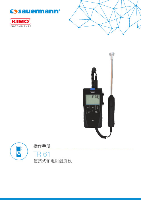
操作手册TR 61便携式铂电阻温度仪1. 产品介绍OK 键背光键选择键ON / OFF / ESC 键Hold / min / max 键2. 执行测量•按下 "ON / OFF / ESC" 键开机。
• 将探头置于测量目标处,仪器显示测量温度。
3. 定格测量值, 显示最大值、最小值当进行测量时:•按下 "Hold / min / max" 键一次,显示当时显示屏上测量参数的测量定格值。
• 再按 "Hold / min / max" 键一次,测量仪屏幕顶部显示两次定格值间的最大值,底部显示最小值。
• 按 "ON / OFF / ESC" 键回到测量模式。
4. 设置测量仪4.1 温度单位设置设置前,保持仪器开机并处于测量模式:• 按下 "选择" 键,直到屏幕上 "UNIT / 单位" 闪烁。
• 按 "OK" 键,屏幕上当前正在使用的单位闪烁。
• 按 "选择" 键,直至出现所需要的单位: °C 或 °F 。
按 "OK" 键确认,屏幕上 "UNIT / 单位" 闪烁。
• 按 "ON / OFF / ESC" 键回到测量模式。
4.2 设置自动关机设置前,保持仪器开机并处于测量模式:• 按下 "选择" 键,直到屏幕上 "AUTO OFF / 自动关机" 闪烁。
• 按 "OK" 键,屏幕底部闪烁仪器自动关机倒计时的时间。
• 按"选择" 键直至出现所需的时长: 15 / 30 / 45 / 60 / 75 / 90 / 105 / 120 分钟或者关闭自动关机功能。
• 按 "OK" 键确认,屏幕上 "AUTO OFF / 自动关机" 闪烁。
热敏标签打印客户端培训

订单处理 打印配货单 打印速递单 装订两单 扫描匹配两单 拣货、出仓 黏贴、包装发货
说明: 采用系统对接模式,提升打印速度,降低打印成本,优化生产作业流程,节省了打印速递单(这个步骤在配货单打印时 同步进行)、扫描匹配两单二个步骤所花费的人力。
系统对接模式
名鞋库标签式详情单打印应用模式:打印配合单时批量
系统登录
3. 将MAC地址交与相关的技术人员进行维护后,此计算机才被授权 登录,否则点击“登录”会出现以下提示:
系统登录
点击桌面快捷方式,进入系统登录页面,输入用户名、密码、验证码点击" 登录"按钮即可;
我的信息管理----用户管理
进入”我的信息管理------用户管理”界面,可以对当前大客户 的子账户进行查询、新增、修改、删除等维护操作;在大客户号 下生成的子账号可以登录自助客户端,并进行热敏打印的相关操 作;用户管理界面如下图所示:
关键说明: 1、预留一行留白信息,大客户可自定义增加(留白1)。 2、寄件人地址保留1行。 关键说明: 1、收件人地址提供3行。 关键说明: 1、留白信息,大客户可自行增加(留白2)。 2、格口信息。
标签式详情单—代收货款模板样例
关键说明: 标签式详情单打印模板说明总部统一下发。收寄日期/打单 时间可选,只能唯一。 关键说明: 应收货款包括大小写。 关键说明: 1、寄件人地址提供1行。 关键说明: 1、收件人地址提供2行;右侧寄达地城市。
4、两单整理
8、售后退换货
7、订单称重
6、验货出库
5、仓库配货
标签式详情单介绍
国内速递“专用标签式详情单” 是为了适应客户需求,以现制的热敏 标签替代传统的预制式特快专递邮件 详情单的新式单据,具有打印速度快、 成本低等优点。
puro YP-DP1 热敏直接打印机操作说明

操作说明热敏直接打印机 Puro®YP-DP198627-000-33版本 1.0.18/3/2020 Minebea Intec Bovenden GmbH & Co. KG, Leinetal 2, 37120 Bovenden, Germany电话:+49.551.309.83.0传真:+49.551.309.83.190前言必须遵守!本文档中的任何信息如有更改,恕不另行通知,除非法律规定,并不代表Minebea Intec做出的任何承诺。
只能由经过培训和合格的人员操作/安装本产品。
在与本产品有关的信函中,必须引用与产品有关的类型、名称、版本号/序列号以及所有许可证号。
注意本文档部分受到版权保护。
未经购买或版权所有者(Minebea Intec)的书面许可,不得擅自修改或复制。
使用本产品即表示您接受上述规定的要求。
热敏直接打印机 Puro®YP-DP1目录目录1介绍 (2)1.1阅读手册 (2)1.2这是使用说明的介绍 (2)1.3这是列表的介绍 (2)1.4这是菜单项和软键的介绍 (2)1.5这是安全指令的介绍 (2)2安全指令 (4)2.1一般信息 (4)2.2进货检验 (4)2.3在启动运行之前 (4)3设备说明 (5)3.1概述 (5)3.2外形尺寸 (6)3.2.1纸格式 (6)4设备安装 (7)4.1电源 (7)4.2数据接口 (7)4.3悬挂打印机 (8)5操作 (9)5.1重量指示器 (9)5.2自检 (9)5.3菜单 (9)5.4换纸 (9)6废物处置政策 (11)7规格 (12)7.1提供的设备 (12)7.2技术数据 (12)8附录 (13)8.1FCC 公告 (13)Minebea Intec ZH-1热敏直接打印机 Puro®YP-DP1 1 介绍1介绍1.1阅读手册-在使用产品之前,请仔细阅读本手册。
-本手册是产品的一部分。
- 1、下载文档前请自行甄别文档内容的完整性,平台不提供额外的编辑、内容补充、找答案等附加服务。
- 2、"仅部分预览"的文档,不可在线预览部分如存在完整性等问题,可反馈申请退款(可完整预览的文档不适用该条件!)。
- 3、如文档侵犯您的权益,请联系客服反馈,我们会尽快为您处理(人工客服工作时间:9:00-18:30)。
华瑞牌热敏版使用说明
一、制版
适用的制版机:市场上所有搭载830nm红外激光头的主流热敏CTP制版机
如:柯达全胜系列,网屏。
由于华瑞牌热敏版感度比较高所以还适用于各种国产机包括保利特、火麒麟。
等
曝光光源及感度:波长为830nm红外激光;120~140mj/cm2
(由于冲版机的不同导致不同的设置,具体制版条件请与我公司技术人员联系进行设定)二、显影
适用的显影机:各种品牌含有自动补加系统的显影机
显影液有:华瑞牌显影液
显影液的配制方法及使用:
华瑞牌显影液为即时使用型显影液,不需再稀释。
显影温度起始温度20度随着显版量增加逐渐增加(以一度为单位)直到27度
显影时间 20-25秒
自动补加:100/小时 50-80ml/张
AM加网:两周或3000㎡(实际使用数可能因为氧化严重而减少)
FM加网:两周或500~1000 ㎡
*由于不同显影机的结构不一样,实际显影参数可咨询我方技术员做适当调整。
推荐参数为:显影温度 20±2℃
显影时间 20±5秒
换液时间有补充:两个星期或1000㎡
三、保护胶
为保持与PS版同样的印刷适性,可使用阳图版的高效保护胶。
四、修版
可使用传统阳图PS版修版液。
涂抹至要修除的部位,放置30-40秒后用水充分冲洗或用海绵擦拭即可(水洗不干净可能会导致上脏)。
五、烤版:不建议烤版(烤版不能显著提高耐印率,并可能由于烤版不当影响印刷质量)注意:
1.因烤版后的感光膜吸附在版面很牢固,所以版子在烤版前一定要将版面上的脏点清除干净。
2.修版后要用清水将修版液冲洗干净,否则烤版后,残余的修版液及被溶解的物质会污染版面,引起上脏。
3.烤版液擦得不宜过多,过多易出现流痕状痕迹,严重时不易着墨。
4.烤版时必须待版面保护液干燥后才可进行烤版。
5.涂烤版保护液要用脱脂纱布,以免用脏布涂擦污染版面,引起上脏。
6. 涂烤版保护液用力不要过大,以免纤维脱落而影响烤版质量。
六、安全灯
白炽灯可放置60分钟,UV滤色灯为120分钟,黄灯为12小时或更长。
七、存储方法
未使用过的华瑞牌热敏版应存放在原包装盒内。
包装盒应放于干燥且阴凉的暗处,温度不超过30℃。
避免放在靠近水箱、干燥机或窗户的地方。
保质期18个月。
*最佳条件为:温度 21~25ºC,每小时温度变化小于2ºC
湿度相对湿度50~60%,每小时变化小于5%。