safety_controller_select
电子手臂机械舵机说明书
Electric Gripper unit LEHF32EK2-64-XA147Safety Instructions (2)1. Electric Gripper unit detail drawing (4)2. Specification (5)3. JXC Controller – UR Control box connection (5)3.1 Controller wiring and connection (5)3.2 Connect to UR control box (5)4. URCap (6)4.1 Install URcap (6)4.2 Connect the electric gripper (6)4.3 Installation Settings (8)4.4 Programs (11)4.5 Manual operation (17)5. Alarm detection and trouble shooting (18)5.1 Alarm detection (18)5.2 Trouble shooting (18)6. Dimensions and Center of gravity (19)6.1 Dimensions (19)6.2 Center of gravity (20)Safety InstructionsThese safety instructions are intended to prevent hazardous situations and/or equipment damage. These instructions indicate the level of potential hazard with the labels of "Caution", "Warning" or "Danger". They are all important notes for safety and must be followed in addition to International Standards (ISO/IEC)*1), and other safety regulations.*1) ISO 4414: Pneumatic fluid power -- General rules relating to systems.ISO 4413: Hydraulic fluid power -- General rules relating to systems.IEC 60204-1: Safety of machinery -- Electrical equipment of machines .(Part 1: General requirements)ISO 10218: Manipulating industrial robots -Safety.etc.Safety InstructionsLimited warranty and Disclaimer/Compliance Requirements The product used is subject to the following "Limited warranty and Disclaimer" and "Compliance Requirements".Read and accept them before using the product.2. SpecificationActuator :LEHF32EK2-64* Please check the LEHF Series catalog from our website ( ).Controller :JXC*1* Please check the LEHF Series catalog from our website ( ).Plugin softwarePolyScope Version 5.11(e-series only )3. JXC Controller – UR Control box connection3.1 Controller wiring and connection* For details on wiring and connection of the controller, refer to "Electric Controller JXC Series Instruction Manual Installation and Initial Setting".3.2 Connect to UR control box1. Connect the communication cable (JXC-W2A-C) and USB cable (LEC-W2-U).2. Connect the communication cable to the JXC controller.3. Connect the USB cable to the USB port of the UR control unit.* For details on the controller such as controller input power supply and actuator cable connection method, refer to the operation manual of each controller.Communication cable JXC-W2A-CUSB cable LEC-W2-UJXC controllerUR control unit.4.4.1Install URcap1. Insert the USB memory to which the downloaded file is copied into the teach pendant.2. Press the menu (hamburger menu icon) in the header and select [Settings].3. Click the System and select URCaps.4. Press the "+" button, select the SMC-ElGripperUnit--xxx.urcap file and press Open.Note: Select the new URCaps in the Active URCaps field for more information.Detailed information is displayed in the URCap Information field.5. Press Restart to continue the URCap installation.⇒URCaps is installed and ready to use.4.2Connect the electric gripperEstablish a serial communication connection between the electric gripper and URCap.1. Press the [Installation] tab and select "SMC Electric Gripper Unit" from the [URCaps] menu.If the LED lamp is already green, the electric gripper connection is complete. The following operations are not required.2. Press the "Connect" button to start communication. It may take 2 to 3 seconds.3. When the controller is connected, the LED light will turn green.Press the [Installation] tab and select "SMC Electric Gripper Unit" from the [URCaps] menu. Then, perform the installation setting "Installation Settings" of the electric gripper URCap.1. Popup a message window and stop operation in error.Select whether to popup a message window and stop operation when the electric gripper unit detects an error. If you check the check box, an alarm message will be displayed when“ Gripping failure or "workpiece drop" is displayed.2. Various status signal output to digital output port.Select whether to output a status signal to the digital output port when "Gripping success", "Gripping failiure", or "workpiece drop” is detected.<“Enable” is selected>Selection of the digital output port is enabled. If any of "Gripping success", "grip failure", or "workpiece drop" is detected, corresponding digital output port is turned on.The operation of the select box becomes enavabled. Select the digital output port that outputs the status signal when "Gripping success", "Gripping failure", or "workpiece drop" is detected.- “grip success”: Select digital output port to output Griping success signal⇒Default output Digital output port [5]- “grip failure”: Select digital output port to output Griping failure signal⇒Default output Digital output port [6]・“Workpiece drop”: Select digital output port to output work-piece drop detection signal ⇒Default output Digital output port [7]* Digital output port can be selected within [0] to [7]※If you select the same digital output port for different status signals, a warning message will be displayed.<Disable is selected>The selection of the digital output port is disabled. If any of "Gripping success", "Gripping failure", or "workpiece drop" is detected, no status signal is output.3. Return to originPerform return to origin.It is necessary to perform a return to origin operation at the first connection when the items below are applicable.- The actuator and the controller were purchased separately.- Only the actuator is replaced.- Only the controller is replaced.URCap nodes can be selected in the URCaps tree.The electric gripper unit URCap has three types of program commands.1. Activate commandUsed to initialize the electric gripper.It needs to be executed only once before executing the Grip command or Release command.During the activation, if an error occurs in communication with the electric gripper or if an alarm occurs in the electric gripper, a pop-up error message will be displayed and the operation will stop.2. Grip commandUsed to grip the workpieces with outer diameter / inner diameter.(1) Select OperationSelect the operation mode of the electric gripper.・Gripper CloseUsed to grip the workpieces with outer diameter.・Gripper OpenUsed to grip the workpieces with inner diameter.(2) SettingsSet the parameters required to grip the workpiece with outer diameter / inner diameter.・Gripping PositionSet the gripping position of the workpiece.[Minimum value]: 2.00mm [Maximum value]: 62.00mm [Initial value]: 2.00mm - SpeedSet the moving speed of the workpiece to the gripping position.[Minimum value]: 5mm/sec [Maximum value]: 30mm/sec [Initial value]: 5mm/sec - ForceSet the pushing force.[Minimum value]: 60N [Maximum value]: 120N [Initial value]: 60N- “Execute” buttonTest the operation of Select Operation with the set Gripping Position value,Speed value, and Force value.During the test run, operations other than the "Stop" button are disabled.If an alarm occurs when moving from the current position to the set Gripping Position value,a pop-up message warning is displayed without performing the move.- "Stop” buttonThe test operation executed by the "Execute" button is stopped.This button acts as a reset button to release the alarm when an alarm occurs on the electric gripper.※“Alarm Code” is displayed when an alarm occurs.For details on "Alarm Code", refer to the operation manual of the JXC controller.(3) Gripper ControlControls the electric gripper position. If the LED lamp is green, the electric gripper is controllable.- Current PositionDisplays the current position of the electric gripper.- "Open Jog” buttonPerforms the opening operation of the electric gripper while the button is pressed.- “Close Jog” buttonPerforms the closing operation of the electric gripper while the button is pressed.- "Fully Open” buttonPerforms a fully open operation of the electric gripper- "Fully Close” buttonPerforms a fully close operation of the electric gripper- "Capture Current Position” buttonCapture the current position of the electric gripper into the "Gripper Position" setting in "Settings".(4) Operation StatusThe test operation executed by the "Execute" button is displayed.- "Execute": T est run is being executed- "Success": Workpiece gripping successful, test operation completed normally- "Failure": Workpiece gripping error occurred, test operation abnormally ended.- "Workpiece lost": Detects workpiece drop after successful workpiece gripping.- "Stop": Stopped by "Stop" button during test operation3. Release commandUsed to release the workpiece(1) Select OperationSet the operation of the command when the workpiece is released.・Wait for the release process to complete.Check box ☑: When the workpiece release command is completed, the next operation is performed.☐:Moves to the next operation without waiting for the completion of the commandwhen the workpiece is released.(2) SettingsSet the parameters required to open the workpiece.- PositionSet the target position[Minimum value]: 1.00mm [Maximum value: 64.00mm [Initial value]: 1.00mm - SpeedSets the speed to travel to the target position.[Minimum value]: 5mm/sec [Maximum value]: 100mm/sec [Initial value]: 5mm/sec - “Execute” buttonTest the operation with the set Position value and Speed value.During the test run, operations other than the "Stop" button are disabled.- "Stop” buttonThe test operation executed by the "Execute" button is stopped.This button acts as a reset button to release the alarm when an alarm occurs on the electric gripper.(3) Gripper ControlControls the electric gripper position. If the LED lamp is green, the electric gripper is controllable.- Current PositionDisplays the current position of the electric gripper.- "Open Jog” buttonPerforms the opening operation of the electric gripper while the button is pressed.- “Close Jog” buttonPerforms the closing operation of the electric gripper while the button is pressed.- "Fully Open” buttonPerforms a fully open operation of the electric gripper- "Fully Close” buttonPerforms a fully close operation of the electric gripper- "Capture Current Position” buttonCapture the current position of the electric gripper into the "Gripper Position" setting in "Settings".(4) Operation StatusThe test operation executed by the "Execute" button is displayed.- "Execute": T est run is being executed- "Success": Workpiece gripping successful, test operation completed normally - "Failure": Workpiece gripping error occurred, test operation abnormally ended.- "Workpiece lost": Detects workpiece drop after successful workpiece gripping.- "Stop": Stopped by "Stop" button during test operation4. Workpiece drop detectionFrom the execution of the Grip command to the next Release command, the grip status of the workpiece is monitored and the workpiece drop is detected.(1) Conditions for starting the workpiece drop detection.- "Various status signal output to digital output port." in "Installation Settings" of the electric gripper URCap is valid.- The Grip command ends successfully.(2) Conditions for the workpiece drop detection.- After starting the detection of the workpiece drop, the status flag "BUSY" and "INP" of the electric gripper are constantly monitored.- When the status flag "BUSY" output of the electric gripper is off and the "INP" output is off, "workpiece drop" is determined to be detected.4.5Manual operationThe manual operation of the electric gripper can be operated using the UR+ icon on the upper right corner of the screen. It can be operated when the LED lamp is green.- Current PositionDisplays the current position of the electric gripper.- "Open jog" buttonThe electric gripper performs opening operation when the button is pressed.- "Close jog" buttonThe electric gripper performs closing operation when the button is pressed.- "Fully Open" buttonThe electric gripper fully opens.- "Fully Close" buttonThe electric gripper fully closes.- "Reset" buttonResets the alarm or the operation.5.5.1Alarm detectionWhen an alarm occurs, an "Alarm Code" is displayed.For details of "Alarm Code", refer to "Electric Controller JXC Series Instruction Manual Alarm Detection".5.2Trouble shootingIf a malfunction occurs, refer to "Electric Controller JXC Series Instruction Manual Troubleshooting" and check the appropriate item.If the cause corresponding to the phenomenon is not confirmed and the product returns to normal by replacement, the product itself may be defective.6.6.1DimensionsXYZYXZ4-14-1, Sotokanda, Chiyoda-ku, Tokyo 101-0021 JAPANTel: + 81 3 5207 8249 Fax: +81 3 5298 5362URL https://Note: Specifications are subject to change without prior notice and any obligation on the part of the manufacturer. © 2023SMC Corporation All Rights Reserved。
西门子洗碗机说明书
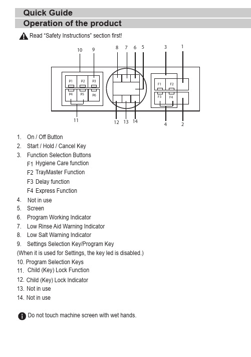
1. On / Off Button2. Start / Hold / Cancel Key3. Function Selection Buttons F1 F2 F3 F44.5. Screen6. Program Working Indicator7. Low Rinse Aid Warning Indicator 8. Low Salt Warning Indicator9. Settings Selection Key/Program Key(When it is used for Settings, the key led is disabled.)10. Program Selection Keys 11. 12. 13.14. Do not touch machine screen with wet hands.Operation of the productHygiene Care function TrayMaster FunctionExpress Function Not in use Delay function Child (Key) Lock Indicator Child (Key) Lock Function Read “Safety Instructions” section first!Quick GuideNot in use Not in use123456A u t oI n t e n s i v e E c o *D e l i c a t e Q u i c k W a s h (#)M i n i (#)40 ºC -65 ºC70 ºC50 ºC 40 ºC 60 ºC 35 ºCI t d e t e r m i n e s t h e s o i l i n g d e g r e e o f t h e d i s h e s a n d s e t s t h e t e m p e r a t u r e a n d a m o u n t o f t h e w a s h i n g w a t e r a s w e l l a s t h e w a s h i n g t i m e a u t o m a t i c a l l y . I t i s s u i t a b l e f o r a l l d i s h t y p e s .I t i s s u i t a b l e f o r h e a v i l y s o i l e d p a n s a n d t r a y s .S u i t a b l e f o r w a s h i n g d i s h e s w i t h n o r m a l a m o u n t o f s o i l. I t i s t h e m o s t e f f i c i e n t p r o g r a m i n t e r m s o f c o m b i n e d p o w e r a n d w a t e r c o n s u m p t i o n . T h i s i s u s e d f o r a s s e s s i n g t h e c o m p l i a n c e w i t h E U 's e c o -d e s i g n d i r e c t i v e .S p e c i a l p r o g r a m m e f o r g e n t l e c l e a n i n g o f d e l i c a t e g l a s s w a r e .I t i s t h e d a i l y w a s h i n g p r o g r a m m e t o w a s h t h e n o r m a l l y s o i l e d l e f t d i s h e s i n t h e f a s t e s t w a y .I t i s s u i t a b l e f o r q u i c k l y w a s h i n g t h e l i g h t l y s o i l e d d i s h e s t h a t h a v e u n d e r g o n e p r e c l e a n i n g p r o c e s s .M e d i u m t o h i g hH i g h M e d i u m L o w M e d i u mL o w++++--+++++++++++-112-18017024510058309,4-12,416.89.514.410.610.80,90-1,451.510.9510.921.180.8D e g r e e o f S o i l i n gE n e r g y (k W h )P r e w a s h W a s h D r y D u r a t i o n (m i n )W a t e r (I ) L o a d i n g C a p a c i t y : 14T h e c o n s u m p t i o n v a l u e s s h o w n i n t h e t a b l e w e r e d e t e r m i n e d u n d e r s t a n d a r d c o n d i t i o n s . D i f f e r e n c e s m a y t h e r e f o r e o c c u r u n d e r p r a c t i c a l c o n d i t i o n s . * R e f e r e n c e p r o g r a m m e f o r t e s t i n g i n s t i t u t e s . T h e t e s t s i n a c c o r d a n c e w i t h E N 50242/60436 m u s t b e c a r r i e d o u t w i t h a f u l l w a t e r s o f t e n e r s a l t d i s p e n s e r a n d a f u l l r i n s e a i d r e s e r v o i r , a n d u s i n g t h e t e s t p r o g r a m m e . T h e v a l u e s g i v e n f o r p r o g r a m m e s o t h e r t h a n E c o 50°C p r o g r a m m e a r e i n d i c a t i v e o n l y . (#) A d d i t i o n a l f u n c t i o n s m i g h t c a u s e c h a n g e s i n p r o g r a m m e d u r a t i o n s .P r o g r a m m e n u m b e r P r o g r a m m e n a m eC l e a n i n g t e m p e r a t u r eAfter the determination of the water hardness:2. Move to “r” position on the screen by pressing the P2 key.3. Set to a proper level by selecting one of the “r:1”,“r:2”,“r:3”,“r:4” or “r:5” positions with the P3 program key.4. To save, exit the settings menu by pressing on/off key of your machine for 3 seconds. Your settings shall be saved automatically.Adjusting the water softening system•Open the tap and let the water flow for approx. 1•strip.Washing, rinsing and drying performance of your dishwasher will improve when the water softening system is adjusted correctly.To adjust the system, first learn the water hardness in your region and adjust as indicated below.Quick Guide17 9314 0100_GRUNDIG_B7_EN/ 14-09-21.(16:08)Perform the same hardness level adjustment that you have set on the control panel also with the regeneration adjustment switch. For example, if you have adjusted to “3” in the•If the hardness level of the water that you use is above 50°dH or if you are using well water, than it is recommended to use filter and water purification devices.•If the hardness level of the water that you use is below 7°dH, there is no need to use salt in your dishwasher. In this case, the Salt Indicator light on the control panel of your dishwasher will light continuously.•If the water hardness is set to level 1, the Salt Indicator will light continuously although it is not necessary to use salt. If you use salt under this condition, salt will not be consumed and the lamp will not illuminate.When moving, you will need to set the water hardness level of your dishwasher again according to the information above, depending on the water hardness of the place you have moved to. If the water hardness level of your machine is adjusted previously, your machine will display the most recent hardness level adjustment.。
L-Acoustics LA4X 维护手册说明书
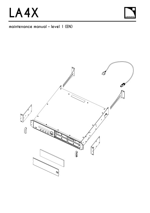
LA4X Arraymaintenance manual – level 1 (EN)ContentsDocument reference: LA4X maintenance manual - level 1 (EN) version 2.0Distribution date: March 20, 2017© L-Acoustics. All rights reserved.No part of this publication may be reproduced or transmitted in any form or by any means without the express written consent of the publisher.ContentsContentsSafety instructions 4 Symbols 4 Revision history 5 Introduction 6 1Equipment and tools 7 2Quality Control 8 3Troubleshooting and diagnosis 10 Diagnosis table (10)Exploded view (16)Working time (16)4Disassembly and Reassembly procedures 17 D/R 001 – REAR BRACKETS (17)D/R 002 – SIDE BRACKETS (18)D/R 003 – GRILL and FOAM FILTER (19)D/R 004 – Power plug (20)D/R 004 bis – FRONT HANDLE (21)Glossary 22 Appendix: KR list 23Safety instructionsSafety instructions1.Strictly follow the sequence of successive steps in all procedures.2.This manual contains the maintenance operations authorized for the end users.Performing another operation exposes to hazardous situations.3.Never incorporate equipment or accessories not approved by L-Acoustics®.4.Do not expose the apparatus to extreme conditions.Do not expose the apparatus to dusty environments, moisture or excessive heat when storing orperforming maintenance procedures.5.Do not store the product on an unstable cart, stand, tripod, bracket, or table.6.Never use a faulty apparatus.An apparatus showing any sign of issue must immediately be put aside and withdrawn from use.7.Contact L-Acoustics for advanced maintenance.Any unauthorized maintenance operation will void the warranty.Before sending a product to L-Acoustics for maintenance, save all user presets to files usingLA Network Manager.SymbolsThe following symbols are used in this document:This symbol indicates a potential risk of harm to an individual or damage to the product.It can also notify the user about instructions that must be strictly followed to ensure safe installation or operation of the product.This symbol indicates a potential risk of electrical injury.It can also notify the user about instructions that must be strictly followed to ensure safe installation or operation of the product.This symbol notifies the user about instructions that must be strictly followed to ensure proper installation or operation of the product.This symbol indicates the equipment, tools, and spare parts required to perform a procedure.This symbol notifies the user about complementary information or optional instructions.Revision historyRevision historyDocument identification Distribution date ModificationsLA4X_MM1_EN_1.0 June 10, 2014 Initial versionLA4X MM1 EN version 2.0 March 20, 2017 - Added D/R 004 bis – FRONT HANDLE- Updated Exploded view- Updated Appendix: KR listIntroductionIntroductionThis manual is intended for end users and gathers the level 1 procedures.This manual contains the maintenance operations authorized for the end users.Performing another operation exposes to hazardous situations.Diagnosis tableThis section contains the diagnosis tables and procedures to identify the issues and how to address them.Exploded viewThis illustration gives an overview of the order in which the elements must be disassembled and reassembled. Each assembly refers to the corresponding module, D/R procedure and inspection procedure (if any).Disassembly and Reassembly proceduresThis section contains the maintenance procedures for each assembly identified in the exploded view.Quality ControlThese checks allow to detect an issue. The quality control must be performed regularly.It is mandatory to perform preventive maintenance actions on a regular basis.Insufficient upkeep of the product can void the warranty.Equipment and tools1Equipment and toolsThe following table is the complete list of equipment and tools required to perform all level 1 maintenance procedures on the LA4X amplified controller.* Refer to the documentation of the electric screwdriver manufacturer to obtain the setting corresponding to a given torque value. This setting can vary depending on the age of the tool. Verify it on a regular basis.Quality Control2Quality ControlThis procedure must be performed for periodic maintenance and to detect possible issues on a controller. ToolsNameaudio source with a known musical programLA NWMCAT5e U/FTP cablefull range loudspeakersubwooferear protectionsProcedureInspect the external structure of the controller for any lost or damaged part.To verify if the controller is clean, follow these steps:a.Disassemble the GRILL and the FOAM FILTER, see procedure D/R 003.b.Verify if the FOAM FILTER is clean.c.Look inside the controller through the front grill (do not touch any part) and verify if the inside is clean.d.Reassemble the GRILL and the FOAM FILTER, see procedure D/R 003.Plug the controller to mains and power it on.Verify if the LCD screen and all LED lit during the start-up sequence.To verify if the network functionalities of the controller work, follow these steps:a.Connect the controller to an Ethernet port of the computer hosting LA NWM.Use the CAT5e U/FTP cable.unch LA NWM.c.Verify if the controller can be put in online mode (refer to the LA NWM video tutorial).Verify if the latest version of firmware is installed (see the LA4X user manual or the LA NWM videotutorial).If not, update firmware from LA NWM.Select a known preset and verify if the indications displayed on screen are in accordance with it.To verify sound presence and quality on each output channel follow these steps:a.Plug the audio source to an input connector of the controller (IN A, IN B, IN C or IN D).b.Plug the full range loudspeaker to output connector OUT1.c.Select a corresponding preset.d.Select the routing from the audio source to OUT1.e.Play the musical program.f.Set the OUT1 gain to -40 dB.g.Unmute OUT1.h.Set the OUT1 gain to obtain a medium sound level.i.Verify if the sound is clear and undistorted.j.Mute OUT1.k.Repeat these steps for OUT2, OUT3 and OUT4.Quality Control There is a risk of ear damage due to high sound level.Use ear protections.To verify the power capability of each output channel follow these steps:a.Plug the audio source to an input connector of the controller (IN A, IN B, IN C or IN D).b.Plug the subwoofer to output connector OUT1.c.Select a corresponding preset.d.Select the routing from the audio source to OUT1.e.Play the musical program.f.Set the OUT1 gain to -40 dB.g.Unmute OUT1.h.Set the OUT1 gain to obtain a high sound level.i.Verify if the sound remains clear and undistorted up to the limit level.j.Mute OUT1.k.Repeat these steps for OUT2, OUT3 and OUT4.Troubleshooting and diagnosis3Troubleshooting and diagnosisDiagnosis tableFor any issue, follow the check sequence in the possible causes column.At each step, apply the inspection procedure (if exists) and consider the resulting diagnosis.Before applying a procedure, consider the EXPLODED VIEW to get acquainted with the disassembly/reassembly procedures to perform before and after.Troubleshooting and diagnosisPOWER CORD notconnected to mainsmains failure or wrongvoltagePOWER CORDdamagedother causecontroller connected to anon-compatible networkcondensing humidity intothe LCD screenother causeTroubleshooting and diagnosisTroubleshooting and diagnosisroom temperature too highFOAM FILTER cloggedcontroller not gettingenough cool airchannel x resourcessolicited to their limitsloudspeaker impedance toolowother causesporadic errorother causesfirmware update failureother causeTroubleshooting and diagnosisFAN blades blockedanythe mains failureoutputs mutedwrong input modewrong preset selectiongain value too low on the controlleraudio source not plugged or plugged into the wrong input connectoraudio source cable incorrectly plugged audio source cable damagedwrong settings on the audio sourcenon-audio bit stream audio source failureloudspeaker not plugged or plugged into the wrong output connector loudspeaker cable incorrectly plugged loudspeaker cable damagedloudspeaker damaged other causesTroubleshooting and diagnosisAES/EBU audio sourceconnected to anANALOG inputgain value too high onthe controlleroutput gain value toohigh on the audio sourceswitch to the analogfallback mode withwrong AES/EBU inputgain valuewrong preset selectionaudio source cableincorrectly pluggedaudio source cabledamagedwrong settings on theaudio sourceaudio source failureloudspeaker pluggedinto the wrong outputconnectorloudspeaker cableincorrectly pluggedloudspeaker cabledamagedloudspeaker damagedother causesTroubleshooting and diagnosisExploded viewThe following exploded view represents the external MODULES of the LA4X. Each MODULE is indicated by a circled number. The orange lines represent the disassembly/reassembly (D/R) order. Refer to the table below for more information.Working timeDisassembly and Reassembly procedures4 Disassembly and Reassembly proceduresD/R 001 – REAR BRACKETS Spare parts KR LABRACKETDisassembly procedureThis procedure describes how to replace the REAR BRACKETS of an LA4X amplified controller. Remove the two REAR BRACKETS pulling on them, see Figure 1.Figure 1: Removing the REAR BRACKETSReassembly procedureThis procedure describes how to mount the REAR BRACKETS kit to an LA4X amplified controller. Insert the two REAR BRACKETS pushing on them until they are locked, see Figure 2.Figure 2: Mounting the REAR BRACKETSDisassembly and Reassembly proceduresD/R 002 – SIDE BRACKETSToolsNameelectric screwdriverTorxSpare partsKR LA4XEQAVDisassembly procedureThis procedure describes how to remove the SIDE BRACKETS from an LA4X amplified controller.Undo the four Torx® screws from the locations indicated in Figure 3.Use the electric screwdriver with the Torx® T10 bit.Figure 3: Removing a SIDE BRACKET Remove the SIDE BRACKET from the controller.Repeat these steps for the other SIDE BRACKET.Reassembly procedureThis procedure describes how to mount a SIDE BRACKETS kit to an LA4X amplified controller.Position a SIDE BRACKET on the controller.Drive four Torx® screws to the locations indicated in Figure 4.Use the electric screwdriver with the Torx® T10 bit. Torque to 1 N.m.Figure 4: Mounting a SIDE BRACKET Repeat these steps with a second SIDE BRACKET on the other side of the controller.Disassembly and Reassembly proceduresD/R 003 – GRILL and FOAM FILTER ToolsName3.5 mm flat screwdriverSpare parts KR LA4XGRI KR LA4XMOU Disassembly procedureThere is a risk of electrical injury and a risk of trapping finger/handBefore any maintenance operation, disconnect the controller from mains and wait for 1 minute so the capacitors discharge completely.This procedure describes how to remove the GRILL and FOAM FILTER from an LA4X amplified controller. Insert the head of the screwdriver in the hole indicated in Figure 5.Figure 5: Removing the GRILLPush the internal latch with the screwdriver and pull out the right side of the GRILL. Push the internal latch with the screwdriver again until the latch comes out of the hole. Remove the GRILL and the FOAM FILTER from the controller.If the FOAM FILTER is intended to be cleaned, use mild dishwashing detergent or soap and then dry it.Reassembly procedureThis procedure describes how to mount a GRILL kit and a FOAM FILTER kit to an LA4X amplified controller. Place a FOAM FILTER into the GRILL.Insert the left side of the GRILL into the controller. Insert the internal latch into the controller. Use the screwdriver.Push on the right side of the GRILL until hearing a click sound.Disassembly and Reassembly proceduresD/R 004 – Power plugToolsNamewire stripping pliersStanley knifescrewdriver adapted to the new powerplugSpare partsSafetyThere is a risk of electrical injury when the high-voltage capacitors are charged.Before the maintenance operation, disconnect the POWER CORD from the mains and from the controller.Replacement procedureThis procedure describes how to replace the power plug on a POWER CORD.Unplug the POWER CORD from the mains.Unplug the POWER CORD from the controller.Cut the POWER CORD near the power plug.Use the Stanley knife.Strip the three wires of the POWER CORD on a length compatible with the new plug.Use the Stanley knife and the wire stripping pliers.Fix the three wires on the new plug according to the color code of Table 1.Use the screwdriver.Table 1: Wire color codeDisassembly and Reassembly proceduresD/R 004 bis – FRONT HANDLEToolsNameelectric screwdriverTorxSpare partsG03255Disassembly procedureThis procedure describes how to remove the FRONT HANDLE from an LA4X amplified controller.1.Undo the two Torx® screws from the locations indicated in Figure 6.Use the electric screwdriver with the Torx® T15 bit.2.Remove the FRONT HANDLE from the controller.3.Repeat these steps for the other FRONT HANDLE.Reassembly procedureThis procedure describes how to mount a FRONT HANDLE to an LA4X amplified controller.FRONT HANDLES can only be mounted on compatible FRONT STRUCTURE.To upgrade a controller with a non-compatible FRONT STRUCTURE, contact your L-Acoustics representative.Self-drilling screwsFor safety reasons, always reassemble new FRONT HANDLES.1.Position a FRONT HANDLE on the controller.2.Drive two Torx® screws to the locations indicated in Figure 6.Use the electric screwdriver with the Torx® T15 bit. Torque to 1 N.m3.Repeat these steps for the other FRONT HANDLE.Figure 6: Mounting a FRONT HANDLEGlossaryGlossaryCE EuropeCN ChinaD/R disassembly/reassemblyKR Replacement KitLA NWM La Network Manager remote control softwareMODULE part of an amplified controller, written in uppercase characters N.m newton meter, international torque unit, 1 N.m = 9 in.lb fUS United StatesAppendix: KR list Appendix: KR listL-Acoustics, an L-Group Company13 rue Levacher Cintrat – 91460 Marcoussis – France+33 1 69 63 69 63 –********************L-Acoustics GmbH Steiermärker Str. 3-5 70469 StuttgartGermany+49 7 11 89660 323L-Acoustics Ltd.PO. Box Adler Shine - Aston HouseCornwall Avenue - London N3 1LFUnited Kingdom+44 7224 11 234L-Acoustics Inc.2645 Townsgate Road, Suite 600Westlake Village, CA 91361USA+1 805 604 0577。
E5CSL E5CWL温度控制器使用说明书

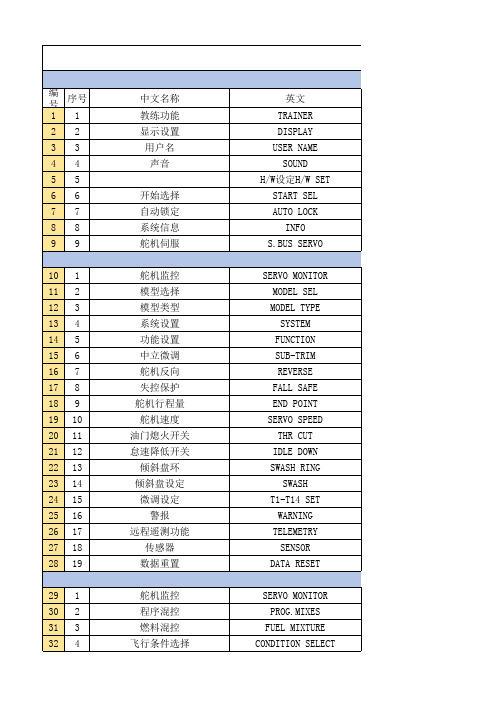
E5CSL/E5CWL T emperature Controller Instruction Manual Thank you for purchasing the OMRON E5CSL/E5CWL Temperature Controller. This manual describes the functions, performance, and application methods needed for optimum use of the product.Please observe the following items when using the product.• This product is designed for use by qualified personnel with a knowledge of electrical systems.• Before using the product, thoroughly read and understand this manual to ensure correct use.• Keep this manual in a safe location so that it is available for reference whenever required.©All Rights Reserved Suitability for Use OMRON shall not be responsible for conformity with any standards, codes, or regulations that apply to the combination of the products in the customer's application or use of the product. Take all necessary steps to determine the suitability of the product for the systems, machines, and equipment with which it will be used.Know and observe all prohibitions of use applicable to this product.NEVER USE THE PRODUCTS FOR AN APPLICATION INVOLVING SERIOUS RISK TO LIFE OR PROPERTY WITHOUT ENSURING THAT THE SYSTEM AS A WHOLE HAS BEEN DESIGNED TO ADDRESS THE RISKS, AND THAT THE OMRON PRODUCT IS PROPERLY RATED AND INSTALLED FOR THE INTENDED USE WITHIN THE OVERALL EQUIPMENT OR SYSTEM.See also product catalog for Warranty and Limitation of Liability.CAUTION Do not touch the terminals while power is being supplied. Doing so may occasionally result in minor injury due to electric shock.Do not allow pieces of metal, wire clippings, or fine metallic shavings or filings from installation to enter the product. Doing so may occasionally result in electric shock, fire, or malfunction.Do not use the product where subject to flammable or explosive gas. Otherwise, minor injury from explosion mayoccasionally occur.Never disassemble, modify, or repair the product or touch any of the internal parts. Minor electric shock, fire, or malfunction may occasionally occur. If the output relays are used past their life expectancy, contact fusing or burning may occasionally occur. Always consider the application conditions and use the output relays within their rated load and electrical life expectancy. The life expectancy of output relays varies considerably with the output load and switching conditions.Tighten the terminal screws to between 0.74 and 0.90 N·m. Loose screws may occasionally result in fire.Set the parameters of the product so that they are suitable for the system being controlled. If they are not suitable, unexpected operation may occasionally result in property damage or accidents.EN Models with Single Display Models with Dual Display E5CSL- R Relay output: 250 VAC, 3 A Q Voltage output (for driving SSR): 12 VDC, 21 mA Control output 131Sensor type 31 Relay output: 250 VAC, 1 A (resistive load)Alarm (E5CWL only)2E5CWL- 1123• Insert the Controller through the hole in the panel. Push the adapter on from therear to secure the Controller.• Make sure that the surrounding temperature does not exceed the allowable operating temperature given in the specifications, especially when two or more Controllers are mounted.• The voltage output (control output) is not electrically isolated from the internalwiring. One or the other of the control output terminals must therefore be leftungrounded when using a grounded thermocouple thermometer. (If both are grounded, measurements will be unreliable due to sneak current.)Individual Mounting Side-by-side Mounting TC Thermocouple (K, J, T, R, or S)P Platinum resistance thermometer (Pt100)The standby sequence is cleared when the alarm OFF condition has been met.The standby sequence is started again when any of the following conditions is met.• Operation is started (power is turned ON or operation is switched from stop to run).• The alarm value is changed.• The temperature input offset is changed.• The set point is changed.Standby sequence clearedAlarm value Alarm with standby sequenceProcess value TimeAlarm without standby sequence Example: Deviation Lower Limit Standby Sequence ONThe default alarm type is 2.• The control output and the alarm output will turn OFF when an error occurs.(For s.err , the alarm output will be processed for a high temperature error.)• If the input value exceeds the display limit (-1999 to 9999) but it is still within the control range, [[[[ will be displayed for values under -1999.Under these conditions, the control output and alarm output will operate normally.*1: This error is displayed only when the process value and set point are displayed.*2: If the display does not change, the Controller needs to be repaired.If operation returns to normal, then noise may have caused the problem. Check for noise.*3: On the E5CSL, e111 and sum will alternate on the display at 1-second intervals.On the E5CWL, e111 will be displayed on display No. 1 and sum will be displayed on display No. 2. * * * * *The default input type is 8.The default input type is 0.−300 to 23000.0 to 900.0−100 to 15000.0 to 750.0−300 to 700−199.9 to 700.00 to 30000 to 3000−200 to 1300−20.0 to 500.0−100 to 850−20.0 to 400.0−200 to 400−199.9 to 400.00 to 17000 to 1700Input Setting range (°C)Setting range (°F)t -n i l.adj t p a o Input Typeinpt at AT Execute/Cancel d-u Temperature Unit s n i t p k o TemperatureInput Shift cntl PID • ON/OFF al-1Alarm Value*E5CWL only p Proportional Band cp Control Period r-s RUN/STOP i Integral Time oreV Direct/ReverseOperation d Derivative Time alt1Alarm Type *E5CWL only of-r hys HysteresisOperation/Adjustment Protect Initial Setting Protect Operation Control Key Protect PV/SP Set Point *E5CSL only Manual Reset Value Adjustment Level 100SP 25SP for less for at least 3 seconds.Protect Level Operation Level +Adjustment Level POWER ON Initial Setting Level 100 to 240 VAC, 50/60 Hz85% to 110% of the rated voltageApprox. 3.5 VARelay output: 250 VAC, 3 A (resistive load)Voltage output (for driving SSR): 12 VDC+25%/−15%, 21 mA Relay output: 250 VAC, 1 A (resistive load)ON/OFF or 2-PID control 100,000 operations 250 ms −10 to 55°C (with no freezing or condensation)Thermocouple: K, J, T, R, or S (JIS C 1602-1995 and IEC 60584-1)Platinum resistance thermometer: Pt100(JIS C 1604-1997 and IEC 60751)Control output Recommended fuse Weight Degree of protection Alarm output Control method Electrical life of relay Sampling period Malfunction vibration Vibration resistance Ambient temperature Ambient humidity Storage temperature Altitude Installation environment Memory protection Indication accuracy (ambient temperature: 23°C)25% to 85%Power supply voltage Operating voltage range Power consumption −25 to 65°C (with no freezing or condensation)2,000 m max.T2A, 250 VAC, time-lag, low-breaking capacity Approx. 100 g (Controller only)Front panel: IP50, Rear case: IP20,Terminal section: IP00Installation category II,pollution degree 2 (as per IEC 61010-1)Non-volatile memory(number of write operations: 100,000)Sensor type Alarm type No alarm Deviation upper/lower limit Deviation upper limit Deviation lower limit Deviation upper/lower range D eviation upper/lower limit standby sequence ON Deviation upper limit standby sequence ON Deviation lower limit standby sequence ON Absolute value upper limit Absolute value lower limit Absolute value upper limit standby sequence ON Absolute value lower limit standby sequence ON Do not set.Output OFF Positive alarm value (X)Negative alarm value (X)Always ON Always OFF Always OFF Process value LevelSetting Adjustment LevelOperationLevel PV/SPOthers (Alarm Value): Operation control keys are enabled but operation control using parameters is disabled.: Operation control keys are disabled but operation control usingparameters is enabled.: Operation control keys and operation control using parametersare disabled.Default: 0Operation ControlAT Execute/Cancel (M +D )RUN/STOP (M +U )01234SettingLevel 10Do not set.2SettingInitial Setting Level Default: 1• Operation/Adjustment Protection • Initial Setting Protection • Operation Control Key Protection+−AB B Pt inputAlarm Output• Relay output: 250 VAC, 1 A(resistive load)Input power supply:100 to 240 VAC,50/60 HzDO NOT USE Control output +−TC inputM M MM M M M MM M M M M M MM M Step 3Adjustment Level: Used to tune parameters and set control parameters. Adjustment Level AT Execute/Cancel Temperature Input Shift Proportional Band Integral Time Derivative Time Manual Reset Value Hysteresis l.adj at ins p i d of-r hys This display indicates that you have moved to Adjustment Level.Starts and stops autotuning. (Displayed only when PID control is selected.)*1*2Set a compensation value for the temperature input in increments of 0.1°C or 0.1°F.Set the proportional band in increments of 0.1°C or 0.1°F.(Displayed only when PID control is selected.) Set the integral time in increments of 1 s. (Displayed only when PID control is selected.) Set the derivative time in increments of 1 s. (Displayed only when PID control is selected.) Set the manipulated value to use for P or PD control (I = 0). The offset will be canceled. Set the hysteresis to use to achieve stable operation when switching the control output ON/OFF during ON/OFF control. (Displayed only when ON/OFF control is selected.) off /on -199.9 to 999.90.1 to 999.90 to 39990 to 39990.0 to 100.00.1 to 999.9OFF 0.0 (°C)8.0 (°C)233 (s)40 (s)50.0 (%)1.0 (°C)Step 4Protect Level: Used to set parameters to restrict key operations.Operation/Adjustment Protect Initial Setting Protect Operation Control Key Protect oapt inpt okpt Set protection for Operation Level and Adjustment Level.Set protection for Initial Setting Level. Set protection for the AT Key and RUN/STOP Key (operation control keys). *Refer to table on the right.*Refer to table on the right.*Refer to table on the right. 010Step 2Operation Level: Used to monitor the process value and to set the set point, alarm value, etc.PV/SP Alarm value RUN/STOP Monitor the process value and set the set point.Set the alarm value. The location of the decimal point depends on the input type. *E5CWL only.Start and stop control operation. *1-1999 to 9999run /stop SV: 0 (°C)0 (°C)RUN Display Parameter name Description Setting/monitoring range Default Step 1Initial Setting Level: Used to set basic specifications.Input Type Temperature Unit PID • ON/OFF Control Period Direct/Reverse Operation Alarm Type in-t d-u cntl cp ore?alt1Set the input sensor type.Set the unit for temperature input to Celsius (°C) or Fahrenheit (°F).Set either 2-PID control or ON/OFF control.Set the time-proportional control period for the control output. (Displayed only when PID control is selected.) Set either reverse option (heating control) or direct operation (cooling control). Set the alarm type.*E5CWL only.c (°C)/f (°F)onof /pid 0.5, 1 to 990 or 8°C ON/OFF 20 or 2 (s)Or-r (reverse control)2 (Deviation upper limit)or-r (reverse control)or-d (direct control)*1: Displayed only when Operation Control Key Protection is set to 4.*2: The setting cannot be changed during autotuning. Autotuning will be stopped if you move to Initial Setting Level or stop control operation. • Displays during AutotuningE5CSL: The current deviation indicator will flash. E5CWL: The AT Execute/Cancel characters on display No. 1 and the PV/SP characters on display No. 2 will flash.K J T R S Setting 01234567Check the wiring of inputs, disconnections, short circuitsand input type.T urn the power OFF then back ON again.*2Press the U and D Keys for at least 3 seconds to initialize the settings and clear the non-volatile memory error.*2Display Action s.err (S.ERR)e111(E111)e111/sum (E111)/(SUM) *3Meaning Input error *1RAM memory error Non-volatile memory memory error −300 to 1500−199.9 to 900.0−200 to 850−199.9 to 500.0Pt10089Safety Precautions Indicates a potentially hazardous situation which, if not avoided, is likely to result in minor or moderate injury or property damage. Read this manual carefully before using the product.CAUTION Package Contents • Temperature Controller • Adapter • Instruction Manual 460645844.8×44.848×48Adapter • Solderless terminal size: M3.5• Terminal Cover: E53-COV19 (sold separately)• Front Panel: E53-COV20 (sold separately)Recommended panel thickness is 1 to 5 mm.1(10) D Down Key: Reduces the setting.(11) U Up Key: Increases the setting.(12) O +M Press these keys for at least 3 seconds in Operation Level or Adjustment Level to go to Protect Level.Press these keys for at least 1 second in Protect Level to return to Operation Level.(13)M +D Press these keys for at least 2 seconds to start or stop autotuning.*1(14) M +U Press these keys for at least 2 seconds to start or stop operation.*2(3)(7)(4)(9)(8)(12)(13)(14)(11)(12)(13)(14)(11)(10)(2)(1)(10)(6)(6)(7)(8)(5)(1)(9)E5CSL E5CWL D Key or U Key Input Type Parameter Display Parameter SettingDisplay Press the U or D Key at the display for the parameter for which the setting is to be changed. The parameter setting display will appear.Use the U or D Key to change the setting. Example: Changing the Input Type from 0 to 1in-t 0Procedure for Changing E5CSL Settings After 2 seconds U Flashes quickly.Setting confirmed.*1: These keys are disabled when starting and stopping autotuning has been disabled with operation control key protection.*2: These keys are disabled when starting and stopping operation has been disabled with operation control key protection.Control Output• Relay output: 250 VAC, 3 A (resistive load)• Voltage output (for driving SSR): 12 VDC, 21 mAAlarm hysteresis(always 0.2 °C/°F)23457891045+0.60+1.004560 min.+0.6045+0.60(48 x number of Controllers − 2.5)OMRON CORPORA TION Key to Warning Symbols Warning Symbols SpecificationsWiring Model Number Legends Dimensions (mm)Installation (mm)Connections Front Panel Part Names and Functions(1) Display No. 1 Displays the process value (PV) or parameter. For the E5CSL, the set point or parameter setting is also displayed.(2) Display No. 2 Displays the set point (SP) or parameter setting.(3) Deviation Indicators Show the relation between the process value and the set point. Lit: The process value is more than 5°C/°F higher than the set point. Lit: The process value is more than 5°C/°F lower than the set point. Lit: The process value is within 5°C/°F of the set point. The relevant deviation indicator will flash during autotuning.(4) SP Lit while the set point is displayed on display No. 1 (E5CSL only). (5) ALM Lit while the alarm is ON. Not lit while the alarm is OFF. (6) OUT Lit while the control output is ON. Not lit while the control output is OFF.(7) STOPNot lit during operation. Lit while operation is stopped.(8) O Level Key: Changes the setting level.(9) M Mode Key: Changes the parameter within the setting level.Operation MenuParameter Operations Press Press than 1 second.for at least 1 second.Press Parameter Tables Display Parameter name Description Setting/monitoring range Default Display Parameter name Description Setting/monitoring range Default Display Parameter name Description Setting/monitoring range Default *Refer to table on the right.*Refer to table on the right.al-1r-s Input type: Thermocouple Input Setting range (°C)Setting range (°F)Setting Input type: Platinum Resistance Thermometer Troubleshooting Protection : Can be displayed and changed.: Can only be displayed.: Display or changing to another level is not possible.0 1 2 311OMRON EUROPE B.V.Wegalaan 67-69, NL-2132 JD Hoofddorp The NetherlandsPhone 31-2356-81-300 FAX 31-2356-81-388OMRON ELECTRONICS LLCOne Commerce Drive Schaumburg, IL 60173-5302 U.S.APhone 1-847-843-7900 FAX 1-847-843-7787OMRON ASIA PACIFIC PTE. LTD.No. 438A Alexandra Road # 05-05/08 (Lobby 2),Alexandra Technopark, Singapore 119967 Phone 65-6835-3011 FAX 65-6835-2711OMRON Corporation Shiokoji Horikawa, Shimogyo-ku, Kyoto 600-8530 JAPAN Malfunction shock Shock resistance 10 to 55 Hz, 20 m/s 2 for 10 min each in X, Y and Z directions 10 to 55 Hz, 20 m/s 2 for 2 h each in X, Y and Z directions100 m/s 2, 3 times each in X, Y, and Z directions300 m/s 2, 3 times each in X, Y, and Z directionsMd-u Next Parameter Display*The dimensions are the same for the E5CSL.(±0.5% of indication value or ±1°C, whichever is greater)±1 digit max.R, S thermocouple at 200°C or less: ±3°C ±1 digit max.K, T thermocouple at −100°C or less: ±2°C ±1 digit max.Use a deviation alarm to link the alarm to the SP.If the SP is changed, the alarm operating point will also change.Deviation AlarmUse an absolute value alarm when the alarm is not linked to the SP.Absolute Value Alarm0X ON OFF SP X ON OFF SP X ON OFF SP X ON OFF 0X ON OFF 0X ON OFF 0X ON OFF 0X ON OFF ON OFF SP X XSP XON OFF SP XON OFF SP X X ON OFF SP X X ON OFF SP X ON OFF SP X ON OFF 0X ON OFF0XON OFF 0X ON OFF Set this difference.SP Linked Fixed Set the difference(deviation) from the SP.Set the alarm operating point as the temperature (absolute value).Set the temperature (absolute value) at which to output an alarm.0* Alarms with a Standby SequenceSP X ON OFFAlarmsSetting 0 1 2 3 4 5 6 7 8 9 1011 12Alarm operating point Alarm operating point The alarm is blocked until the first safe-state is reached.Unwanted alarm during start-up are prevented.Deviation/ab solute value alarm Deviation alarmDeviationalarm DeviationalarmDeviation alarm Deviation alarm Deviationalarm Deviationalarm Absolute value alarm Absolutevalue alarm Absolute value alarmAbsolute value alarm Be sure to observe the following precautions to prevent operation failure, malfunction, or adverse affects on the performance and functions of the product. Not doing so may occasionally result in unexpected events.(1) The product is designed for indoor use only. Do not use the product outdoors or in any of the following locations. •Places directly subject to heat radiated from heating equipment.•Places subject to splashing liquid or oil atmosphere. •Places subject to direct sunlight. •Places subject to dust or corrosive gas (in particular, sulfide gas and ammonia gas). •Places subject to intense temperature change.•Places subject to icing and condensation. •Places subject to vibration and large shocks.(2) Use/store within the rated temperature and humidity ranges. Provide forced-cooling if required.(3) To allow heat to escape, do not block the area around the product. Do not block the ventilation holes on the product.(4) Be sure to wire properly with correct polarity of terminals.(5) Use specified size (M3.5, width 7.2 mm or less) crimped terminals for wiring. To connect bare wires to the terminal block, use copper braided or solid wires with a rated temperature of over 70°C and a gauge of AWG24 to AWG14 (equal to a cross-sectional area of 0.205 to 2.081 mm 2). (The stripping length is 5 to 6 mm.) Up to two wires of same size and type, or two crimped terminals can be inserted into a single terminal.(6) Do not wire the terminals which are not used.(7) Allow as much space as possible between the controller and devices that generate a powerful high- frequency or surge. Separate the high-voltage or large-current power lines from other lines, and avoid parallel or common wiring with the power lines when you are wiring to the terminals.(8) Use this product within the rated load and power supply.(9) Make sure that the rated voltage is attained within two seconds of turning ON the power using a switch or relay contact. If the voltage is applied gradually, the power may not be reset or output malfunctions may occur.(10) Make sure that the Controller has 30 minutes or more to warm up after turning ON the power before starting actual control operations to ensure the correct temperature display. (11) A switch or circuit breaker should be provided close to this unit. The switch or circuit breaker should be within easy reach of the operator, and must be marked as a disconnecting means for this unit.(12) Do not use paint thinner or similar chemical to clean with. Use standard grade alcohol.(13) Design system (control panel, etc) considering the 2 second of delay that the controller’s output to be set after power ON.(14) The output may turn OFF when shifting to certain levels. Take this into consideration when performing control.(15) The number of non-volatile memory write operations is limited.Precautions for Safe Use A malfunction in the Temperature Controller may occasionally make control operations impossible or prevent alarm outputs, resulting in property damage. To maintain safety in the event of malfunction of the Temperature Controller, take appropriate safety measures, such as installing a monitoring device on a separate line.Default: 0: Can be displayed and changed.: Display or changing to another level is not possible.2113603-9A CL1for at least 3 seconds.Press for at least 1 second.+Press。
T14SG英中文对应表(Futaba遥控器)
52 19
翼梢小翼
53 20
电动机控制
54 21
方向舵→升降舵混控
55 22
快速横滚功能
PITCH CURVE THR CURVE THR DELAY AIL DIFFERENTIAL FLAP SETTING AIL TO CAMB.FLP AIL TO BRKFLP AIL TO RUD RUO TO AIL CAMBER MIX ELE TO CAMBER CAMB.FLP TO ELE
所有模式类型
固定翼通用功能 固定翼、滑翔机通用 固定翼、滑翔机通用 固定翼、滑翔机、拥有2副翼以上 固定翼、滑翔机、拥有2襟翼以上 固定翼、滑翔机、拥有2副翼+2襟翼以上 滑翔翼、拥有4襟翼以上 固定翼、滑翔机通用 固定翼、滑翔机通用 固定翼、滑翔机、拥有2副翼以上 固定翼、滑翔机、拥有2副翼以上 固定翼、滑翔机、2副翼+1襟翼以上 滑翔机、拥有2副翼以上(无尾翼机则需2 副翼以上+1襟翼以上) 滑翔机、拥有2副翼以上 固定翼、拥有2副翼以上 固定翼、滑翔机、 通用 V型尾翼结构的固定翼、滑翔机 固定翼、滑翔机、副翼升降舵规格 固定翼、滑翔机、翼梢小翼规格 固定翼、滑翔机 通用功能 固定翼 、通用功能 固定翼 、通用功能
自旋着陆时,发动机熄火的设定 副翼方向、升降舵方向的倾斜盘调整 操作副翼或升降舵时,用于补正由于倾斜盘动作而造成的发动机转数下降 可在操作桨距时用来抑制主旋翼的反扭矩力(Revolution Mixing) 使用Futaba GY 系列陀螺仪时的专用混控 使用Futaba GV-1/GY701/CGY750时的专用混控
BUTTERFLY(CROW)
TRIM MIX AIRBRAKE
GYRO V-TAIL AILEVATOR(DUAL ELEVATOR) WINGLET MOTOR RUD TO ELE SNAP ROLL
wirelesscontroller说明书
wirelesscontroller说明书Wireless Controller User ManualIntroduction:Thank you for purchasing our wireless controller. This user manual will provide you with all the necessary information and instructions on how to use and maximize the features of the controller. Please read this manual carefully before using the wireless controller.Table of Contents:1. Safety Precautions2. Controller Overview3. Charging the Controller4. Pairing the Controller5. Using the Controller6. Special Features7. Troubleshooting8. Technical Specifications9. Warranty Information10. Conclusion1. Safety Precautions:a. Read and understand all instructions before using the wireless controller.b. Avoid exposing the controller to extreme temperatures, direct sunlight, or moisture.c. Do not disassemble, modify, or attempt to repair the controller yourself. This may void the warranty and result in damage.d. Keep the controller away from children and pets.e. Use only the provided charging cable and power source to avoid damage.2. Controller Overview:- It is equipped with various buttons, triggers, and joysticks to enhance your gaming experience.- There is an LED indicator to display the battery level and controller status.- The controller also has a vibration function for added immersion in supported games.3. Charging the Controller:- Before using the wireless controller, it needs to be charged fully.- The LED indicator will light up to show the charging status.- It takes approximately 2-3 hours to fully charge the controller.4. Pairing the Controller:- Ensure that your gaming console or device is turned on and within range.- Press and hold the controller's power button until the LED indicator starts flashing.- On your gaming console or device, navigate to the wireless controller settings and select the controller to pair it.- The LED indicator on the controller will stop flashing and remain solid once the pairing is successful.5. Using the Controller:- The wireless controller functions like a traditional wired controller but without the hassle of cables.- Use the joysticks, triggers, and buttons to navigate menus and control gameplay according to the game's instructions.- The LED indicator will display the battery level by changing color or flashing.- To turn off the controller, press and hold the power button until the LED indicator turns off.6. Special Features:- The controller's built-in rechargeable battery ensures long gameplay sessions without the need for frequent replacements.7. Troubleshooting:- If the controller is not responding or pairing, try resetting it by pressing the small reset button located on the back, near the charging port.- Ensure that the controller is fully charged and within range of the gaming console or device.- Check the device's settings to ensure the controller is recognized and properly configured.8. Technical Specifications:- Wireless technology: Bluetooth 4.0- Battery capacity: 1000mAh- Charging interface: Micro USB9. Warranty Information:- The warranty covers manufacturing defects and malfunctions.- For warranty claims or technical support, please contact our customer support team.10. Conclusion:We hope that this user manual has provided you with the necessary information to use and enjoy our wireless controller. If you have any further questions or need assistance, please refer to the troubleshooting section or contact our customer support. Happy gaming!。
富士施乐S2010_S1810维修手册_1-3章
· 文章开头出现的符号的意义如下。
危险
表示紧急危险情况,操作员如果无视警告,错误地操作机器,将会导致死亡或严重受伤。 警告
表示潜在危险情况,操作员如果无视警告,错误地操作机器,将会导致死亡或严重受伤。 注意
表示潜在危险情况, 操作员如果无视警告, 错误地操作机器, 将会受伤或损坏设备。
指示:若未严格按照指示步骤操作,可能会损坏机器及装置。
9. 有机溶剂 在适用感光鼓清洁剂、 机器清洁剂等有机溶剂时, 应注意以下各事项。 · 应充分注意室内的通风换气, 以免大量吸入。 · 不要在加热的状态下使用。 · 不要靠近火源。 · 使用后应将手清洗干净。
10. 防震处理 [FX] 客户若需要防震措施, 本公司备有防震组件 (ZB38)。
11. 机器的改造使用 改造机器时, 应事先提出改造使用许可申请。
实施维护作业时,应注意以下事项,避免执行错误及不必要的作业。
4. 安全装置 预防机器事故的安全装置 ( 保险丝、 断路器、 联锁开关 ) 及客户操作上的安全装置 ( 控 制面板、 盖子类 ), 都应该确保其安全功能令人满意。 另外, 禁止有损机器安全功能的 改造。
5. 零件的安装、 拆卸 零件、 盖子的边缘部分较锐利。 注意不要触摸到, 若手指、 手上附有油污时, 应擦拭后 再进行作业。 此外, 拉出零件、 电缆等时, 请勿强行拉出, 应慢慢地拉出。
61规格62工具维修消耗品消耗品修改63维修数据64维修模式电气配线数据本章记载本产品的配线连接器列表位置线路网以及bsd相关产品资料未发行安装拆卸本章记载本产品及本产品专用选装品的安装拆卸步骤
DocuCentre S2010/S1810
维修手册 Ver.1.0
DocuCentre S2010/S1810
BL2000串行控制板用户手册说明书
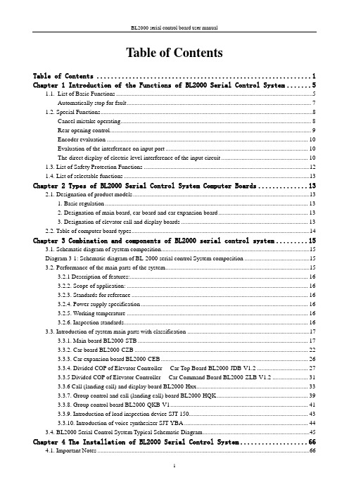
Table of ContentsTable of Contents (1)Chapter 1 Introduction of the Functions of BL2000 Serial Control System (5)1.1.List of Basic Functions (5)Automatically stop for fault (7)1.2. Special Functions (8)Cancel mistake operating (8)Rear opening control (9)Encoder evaluation (10)Evaluation of the interference on input port (10)The direct display of electric level interference of the input circuit (10)1.3. List of Safety Protection Functions (12)1.4. List of selectable functions (13)Chapter 2 Types of BL2000 Serial Control System Computer Boards (13)2.1. Designation of product models (13)1. Basic regulation (13)2. Designation of main board, car board and car expansion board (13)3. Designation of elevator call and display boards (13)2.2. Table of computer board types (14)Chapter 3 Combination and components of BL2000 serial control system (15)3.1. Schematic diagram of system composition (15)Diagram 3-1: Schematic diagram of BL-2000 serial control System composition (15)3.2. Performance of the main parts of the system (15)3.2.1 Description of features: (16)3.2.2. Scope of application: (16)3.2.3. Standards for reference (16)3.2.4. Power supply specification (16)3.2.5. Working temperature (16)3.2.6. Inspection standards (16)3.3. Introduction of system main parts with classification (17)3.3.1. Main board BL2000-STB (17)3.3.2. Car board BL2000-CZB (22)3.3.3. Car expansion board BL2000-CEB (26)3.3.4. Divided COP of Elevator Controller----Car Top Board BL2000-JDB-V1.2 (27)3.3.5 Divided COP of Elevator Controller----Car Command Board BL2000-ZLB-V1.2 (31)3.3.6 Call (landing call) and display board BL2000-Hxx (33)3.3.7. Group control and call (landing call) board BL2000-HQK (39)3.3.8. Group control board BL2000-QKB-V1 (41)3.3.9. Introduction of load inspection device SJT-150 (43)3.3.10. Introduction of voice synthesizer SJT-YBA (44)3.4. BL2000 Serial Control System Typical Schematic Diagram (45)Chapter 4 The Installation of BL2000 Serial Control System (66)4.1. Important Notes (66)4.2. Incoming Inspection (66)4.3. System Installation (66)4.3.1. Technical requirements of installation (66)4.3.2 Installation of BL2000 Series Parts (67)4.3.3. Installation of the system and other parts (67)4.3.4. Grounding of the control system (70)Chapter 5 Parameter setup of BL2000 serial control system (71)5.1. General (71)5.2. Menu structure and flowchart (72)5.2.1. Main menu (72)5.2.2. Communication menu (73)5.2.3. Password verifies (74)5.2.4. Monitor menu and parameter setting menu (74)5.2.5. Notice of menu setup (76)5.3. Setup and operation of monitor parameter menu (76)5.3.1. Monitor menu: all the interfaces are read only except floor select menu and close/open door menu (76)5.3.2. Setup and operation (77)5.4. General parameters menu setting and operation (83)5.4.1. General parameters list (83)5.4.2. Setting and operation (83)5.5. The setting and operation of run parameter menu (95)5.5.1. Table of run parameter (95)5.6. The setting and operation of special parameters menu (102)5.6.1. Special parameter table (102)5.6.2. Setting and operation (103)5.7. The menu setting and operation of other parameters (113)5.7.1. Hoistway self learning (113)5.7.2. Parameter saving (114)5.7.3. Password setting (115)Chapter 6 Debug and Operation of BL2000 Serial Control System (116)6.1. Significant notice (116)6.2. Inspection before power-up (116)6.3. Power-up and inspection (117)6.3.1. Confirmation before power-up (117)6.3.2. Inspection after power-up (117)6.4. Setting of system parameters (118)6.5. Trial Run at Lower Speed (118)6.5.1. Inspection Run of Machine Room (118)6.5.2. Inspection Running of Car Top and Car (119)6.6. Hoistway Self-learning (119)6.7. Trail Run at high speed (119)6.8. Elevator Comfort Adjustment (120)6.8.1. Adjustment of Startup and Brake Curves (120)6.8.2. Adjustment of Running Curve Tracing (121)6.8.3. Adjustment of Elevator Running Control Timing & Sequence (121)6.8.4. Adjustment of Multi-speed Mode (122)6.9. Adjustment of Leveling Precision (125)6.10. Confirmation of Terminal Installation Position (127)Chapter 7 BL2000 Serial Control System Failures Analysis (128)7.1 Running State during Inspection (128)7.2 The low traveling speed and the heavy current during inspection (128)7.3 The speed displayed by the main board is incorrect. (128)7.4 Check on the abnormity of communication (128)7.5 Abnormity of switching power supply (5V/24V) (129)7.6 Checks on no direction and brake output signal (129)7.7 Unlock of the door (130)7.8 Malfunction of elevator arisen from wrong setting of switching value output of load test device (130)7.9 The running direction of elevator is contrary to the instruction (ER04) (131)7.10 Failure on brake on (ER05) (131)7.11 Small number of pulse or no pulse input (ER07) (131)7.12 The output of KDY contactor is inconformity to the feedback result ER09) (132)7.13 The mistake of building floor counter (ER14) (132)7.14 The main board’s not receiving feedback of transducer (ER17) (132)7.15 The value of floor counter is wrong (ER18) (132)7.16 The low-speed adjusting distance is longer than the interval of a single floor (ER19) (132)7.17 Thermal Switch Protection, the brake resistor overheated, or the electric motor overheated (ER25) (133)7.18 The state of contact of gate interlock is inconformity with the state of the coil (ER26) (133)7.19 The inconformity between state of emergency stop contactor and the state of the coil (ER27) (133)7.20 Top or bottom terminal switches adhesion fault (ER28) (133)7.21. Excessive Communication Interference(ER29) (134)7.22. Star-Sealed contactor fault(ER33) (134)7.23. Braking Force Self-testing fault(ER39) (134)Appendix 1 Connection Diagram and Parameter Setting for Inverters Controlled by Asynchronous Motor (135)1.Connection graph and parameter setup menu of Y ASKAWA 616G5, 676GL5-JJ Transducer (135)2.Connection graph and parameter setup menu of Y ASKAWA G7A Transducer (137)3.Connection graph and parameter setup 3.0 version of KEB F4 Transducer (141)4.Wiring diagram and parameter setup menu of FUJI G11UD Transducer (143)5. Wiring diagram and parameter setup menu of FUJI FRENIC-LIFT transducer (146)6.Wiring diagram and parameter setup menu of SIEI Transducer (149)7. Parameter setup menu of WVF5 Asynchronous System Equipping YASKAWA L7B Transducer(Multi-segment) (152)Appendix 2 Connection Diagram and Parameter Settings List of the Inverter Selected for Synchronous Motor Control (156)1.Connection Diagram and Parameter Settings List of Yasukawa 676GL5-IP Inverter (156)2.KEB F4 Inverter Connection Diagram and Parameter Setting 3.0 Version (160)3.KEB F5 Inverter Diagram and Parameter Setting (162)4.Fuji G11UD-4C4 Inverter Connection Diagram and Parameter Setting Table (165)5.Fuji FRENIC-LIFT Inverter Connection Diagram and Parameter Setting Table (168)6.Fuji VG7S Inverter Connection Diagram and Parameter Setting Table (171)7.CT Inverter Connection Diagram and Parameter Setting Table (174)8. SIEI Inverter Connection Diagram and Parameter Setting Table (multi speed) (176)9. Parameter Setting Table for the Yaskawa Inverter for WVF5 Synchronous System (180)10. L7B synchronous motor self-learning method and magnetic pole detection method when self-learning 182 Appendix 3 Reference list of fault codes (184)1. List of system fault codes (184)2. List of hoistway learning fault codes (185)Appendix 4 Operating Instructions of SJT-YY Lift Emergency Automatic Leveling Control Device (187)1. Overview (187)2. Scope of Application (187)3. Model/Specification (187)4. Working Principle and Functions (187)5. Installation and Adjustment (188)6. Fault Analysis and Troubleshooting (190)7. Technical Parameters (191)8. Service and Maintenance (191)Appendix 5 Advance Door Opening/Re-Leveling Instruction (192)1. Safety Circuit Board (SJT-ZPC-V2) Schematic Diagram (192)2. Safety Circuit Board Definition (192)3. Wiring Diagram When BL2000-STB-V2 Main board is used in Advance Door Opening/Re-LevelingFunction (Elevator speed is less than 2 m/sec.) (193)4. Wiring Diagram When BL2000-STB-V9 is used in Advanced Door Opening/Re-leveling Function (194)5. Installation Instructions of Re-Leveling Landing Sensor and Landing Sensor (194)6. Mainboard Parameter Setting (195)7. Hall door and car door separate inspection function (196)Appendix 6 BL2000Floor/Car Door Short-circuited Detection and the Plan for Bypass Operation Alarm (197)1.Rules for type test of control cabinet: (197)2.Testing Plan for Single Door Elevator (197)3.Testing Plan for Double Door Elevator (198)4.Pattern test rules for the new type control cabinet: (200)5. SJT-PLB-V1 bypass circuit board (200)6.Floor/car-door bypass plan (203)Chapter 1 Introduction of the Functions of BL2000Serial Control System1.1.List of Basic Functions1.2. Special Functions1.4. List of selectable functionsChapter 2 Types of BL2000 Serial Control System Computer Boards2.1. Designation of product models1. Basic regulationBL2000—□□□—V□2. Designation of main board, car board and car expansion board(1)Main board BL2000-STB-Vn (2)Car board BL2000-CZB-Vn (3)Car expansion board BL2000-CEB-Vn (4)Group control board BL2000-QKB-Vn(5)For other types, please refer to table of computer board types of 2.2. 3. Designation of elevator call and display boards(1)Code of features: The first H represents call and display boardThe second A: point array vertical display, B: point array horizontal display, C: 7segment vertical display, D: 7 segment horizontal display. The third H: high light, S: over light and R: over high light (2)Version code:The first code represents luminescent diode parameters of digital displaying block.A: 1357 B: 1057 C: 1257 D: 1067VERSION No.: product version upgrade, represented by: V + number ". FUNCTION No.: usages and main technical features of products, represented by the abbreviation of initial alphabet. SERIAL No.E: 2058F: BS252G: BS402The second code means version upgrade, represented by numbers. (3)For the object, please refer to Diagram 3-13.2.2. Table of computer board typesChapter 3 Combination and components of BL2000 serial control system3.1. Schematic diagram of system composition3.2. Performance of the main parts of the systemThe main parts of the system related in the manual means the boards composing of BL2000 serial control system, which consists of: main board, car board, car expansion board, call and display board, group control board, groupcontrol call and display board, voice synthesizer and load inspection device. The serial products of control cabinet with BL2000 serial control system and the other components in BL2000 serial control system are not contained.3.2.1 Description of features:3.2.1.1.Fujitsu industrial control single chip computer;3.2.1.2.Four-layer plate binding process with CAN bus serial communications;3.2.1.3.High intelligence, strong resistance to interference, and high reliability;3.2.1.4.Keyboard operation and liquid crystal display;3.2.1.5.Specialty of elevator operating curve and the leveling precision ≤ 3mm when landing directly;3.2.1.6.Support parallel connection, group control, monitoring and intelligent management;3.2.1.7 Provided with RS-485 communication interface (which can be connected with weight inspectingdevice made by Blue Light to improve elevator startup) ;3.2.1.8 Use portable computer to connect with RS232 interface, being able to choose velocity of elevator incar to comfort passenger.3.2.2. Scope of application:3.2.2.1.Elevator selective-collective operation, two elevators parallel connection and group control of 3-8elevators;3.2.2.2.Range of speed: 0.5-4m/s;3.2.2.3.Applicable story: below 64 floors.3.2.2.4.Passenger elevator, freight elevator, ward elevator and residential elevator;3.2.2.5.With weighting inspecting compensation and fire control linked interface;3.2.2.6.Support wired video monitoring, remote monitoring and wireless remote monitor;3.2.2.7.Applicable to gear towing machine and gearless permanent magnetic towing machine.3.2.3. Standards for reference3.2.3.1.Elevator Manufacture and Installation Regulation (GB7588-2003)3.2.3.2.SJT Serial BL2000Elevator Control System (Q1SL.J02.01-2003)3.2.4. Power supply specificationV oltage: DC24V ±1.2V;current: 2A;V oltage: DC5V ±0.1V;current: 1 A.▲Note: Increa se the power capacity when the building is more than 20 stories. For each story, the increasing value should be ≧100mA.3.2.5. Working temperatureWorking temperature of devices: -40ºC ~ +80ºC (except LCD)3.2.6. Inspection standards3.2.6.1.Inspecting according to GB/T17626.2-1998 Electromagnetic Compatibility- Testing and MeasuringTechniques-Static discharging interference test to make sure the requirements are met (contactdischarging: 8kV;test grade: 4).3.2.6.2.Inspecting according to GB/T17626.3-1998 Electromagnetic Compatibility- Testing and MeasuringTechniques-Radiated, radio-frequency, electromagnetic field immunity test to ensure therequirements are met (frequency domain: 80~1000MHz, filed density: 10V/m, signal: 1kHz sinewave, modulation percentage: 80% and test grade: 3).3.2.6.3.Inspecting according to GB/T17626.4-1998 Electromagnetic Compatibility- Testing and Measuring Techniques-Electrical fast transient/burst immunity test to ensure the requirements are met (power and grounding port-test voltage: 4kV , repetition rate: 2.5kHz) (I/O signal, data, control port-test voltage: 2kV, repetition rate: 5kHz and test grade: 4)3.2.6.4.Inspecting according to GB/T17626.8-1998 Electromagnetic Compatibility-Testing and Measuring Techniques-Power frequency magnetic field immunity test to ensure the requirements are met (field density: 10V/m and test grade: 3).3.3. Introduction of system main parts with classification3.3.1. Main board BL2000-STB1 2 3 4 5 6 7 8 9 10 1 2 3 4 5 6 7 8 9 101 2 3 4 5 6 7 8 9 101 2 3 4 5 6 7 8 9 101 2 3 4 5 6 7 8 9 101 2 3 4 5 6 7 8 9 101 2 3 4 5 6 7 8 9 101 2 3 4 5 6 7 8 9 10J1J8J7J6J5J4J3J24 - Ф3.52312412156157166液晶显示器LED X00~X21LED X22~X23操 作 键 盘衬 板12312345J10J96 75 84 93 A 2 1J11120269252LED Y00~Y154 - 5×10Ф5172Diagram 3-2 Appearance and layout installation dimension of main board BL2000-STB1.Plug specifications(1)rated voltage of J1~J8 multi-wire dipsocket DK5EHDRC-10P: 300V , rated current: 15A, voltage resistance: 4KV, pitch: 5mm (2)J9 single-row pin 2.54/5P (3)J10single-row pin 2.54/3P(4)J11 double-row connector 2.54/10P2.Port circuit Please refer to: Diagram 3-3 Diagram 3-4KeyboarLCD Lining boardDiagram 3-4 Main board BL-2000-STB port circuit3.Definition and specification of portsTable 3-1 Definition and specification of main board BL2000-STB●X15/X28 input: when braking feedback inspection enable is set on “Yes”, X15 is defined to be left brakefeedback input; X28 is defined to be right brake feedback input.●When special function FU-30 is ON, X29 is Star-Sealed contactor feedback input, Y17 is Star-Sealedcontactor control output.●Hall and car door respective inspection functionInspect hall door circuit reply contact with high-voltage input X23+ (J5-3) and X23- (J5-4); inspect car door circuit reply contact with X14 (J2-5); meanwhile, modify the drawing of door circuit reply contact needed to be serial or parallel connected to inspect hall and car doors circuit respectively. (For detailed drawings, please contact the technical office of our company.)3.3.2. Car board BL2000-CZB模式跳线Mode Selection JumperDiagram 3-5 Appearance and layout installation dimension of car board BL2000-CZB 1.Instruction(1) Internal selecting and responseBesides basic input and output ports, Car board BL2000-CZB is provided with internal selecting button and response port of 8 floors. When it is connected to car expansion board, the control of 64 floors can be achieved.(1)Car internal displayCar internal display can be achieved by call and display board. For the layout of its ports, refer to Diagram 3-8. When call and display board is used for internal display, J1 is connected to car board J1, J2 and J3 are di sconnected with wires, as well as the story address is set on “0” (please refer to the setup of call and display board address).2.Connector specification (BL2000-CZB-V7)(1)J1 single-row socket 3.96/4P(2)J2~J6, JN1~JN8 single-row pin 2.54/4P (single jacket)(3)J7 single-row socket 2.54/5P(4)J8 double-row hole 2.54/10P(5)J9~J11 multi-wire swan neck socket DK5EHDRC-10PRated voltage: 300V, rated current: 15A, voltage resistance: 4KV, pitch: 5mm.(6)J12 double-row socket 2.54/14P3Port circuit4definition and specification of portContinue Table 3-23.3.3. Car expansion board BL2000-CEBDiagram 3-9 Appearance and layout installation dimension of car expansion board BL2000-CEB1. InstructionCar board BL2000-CZB itself can connect with car call and response command signal; when the number of floors exceeds 8, it concatenates the car expansion board BL2000-CEB by port J12. Each car expansion board can increase the car call command for 8 floors. The car expansion boards themselves are cascade connection. The maximum number of the concatenatedboards is 7.2. connector specification (BL2000-CEB-V1/V2)(1)J1~J2 double-row socket 2.54/14P(DC2-04) (2)JE1~JE8 single jacket andsingle-row pin 2.54/4P (2510-4P) 3. Port circuit4. Definition and specification of portLining boardTable 3-3 Definition and specification of ports on car expansion board BL2000-CEB3.3.4. Divided COP of Elevator Controller----Car Top Board BL2000-JDB-V1.2Shape and flat setting size of Car Top Board BL2000-JDB-V1.2 is shown below in Figure 3.11.F IGURE 3.11 C ALL TOP B OARD BL2000-JDB-V1.2 S HAPE & D IMENSION1. FunctionCar Top board is installed on car top. It mainly achieves car door information collection & load weigh collection & door control output. Car Top board and Car Command board are connected by DB9 cable. Car Top board can only connect to main Car Command board, and also can connect to both main Car Command board and sub Car Command board.Through DIP switch SW1 on Car Top board, you can select functions. First, power off, set DIP switch as requirement, then power on and Car Top board will enter program with corresponding function. While actual operation, select function according to actual configuration (with or without sub Car Command board).Chart 3.4 Function SettingNote: Main Command board & Sub Command board & Sub Command board of rear door are all BL2000-ZLB-V1.2.2.Function description:This program support IC Card Function and visitor function of COP board. According to configuration of sub command board, it can be divided to such following types:(1) Standard Program: Suit for single door or whole two-door (No sub command board or connect to rear door command board).(2) Sub (front door) command board Program: Suit for no sub command board or connect to normal sub command board. This mode support interlaced two doors.(3) CAN Communication COP Program: No command board in car, but Car Operation board (BL2000-CZB) in car for information exchange with CAN Bus.Terminal SpecificationBL2000-JDB-V1.2 Board Terminal Specification:1.J1 Single Pin Bar 3.96/4P2.J2 Straight pin socket 5.08/10P3.J3 Straight pin socket 5.08/5P4.J4 Straight pin socket 5.08/10P5.J5 Straight pin socket 5.08/10P6.J6 Single Pin Bar 3.96/10A;7.J7 D-Type 9 pin socket;8.J8 D-Type 9 pin socket;3.Terminal Definition & SpecificationChart 3.5 Car Top Board BL2000-JDB-V1.2 Terminal Definition/Specification ListNote:[1] If using both safety plate and light curtain at same time, J2-4 and J2-8 will be safety plate input, J2-5and J2-9 will be light curtain input; If only using safety plate or light curtain, J2-4 and J2-8 will be their input.[2] Connect to J1 of command board through communication cable (DB9 female cable).3.3.5 Divided COP of Elevator Controller----Car Command Board BL2000-ZLB-V1.2Shape and flat setting size of Car Top Board BL2000-ZLB-V1.2 is shown below in Figure 3.12.F IGURE 3.12C ALL TOP B OARD BL2000-ZLB-V1.2S HAPE &D IMENSION1.Function descriptionCar Command Board is installed in COP box. It mainly achieves information collection of car call input & answer and open/close door input & answer and inspection box. Car Top board and car command board are connected through DB9 cable. Car top board can connect only main command board, or both main and sub command board.SW.1 and SW.2 DIP switch on main command board BL2000-ZLB-V1.2 can be used as IC Card enable control or turn ON/OFF IC card control function of some floor. The detail is in Chart 3.6.Chart 3.6 IC card control setting1. IC card control enable (All Floors use IC card control) :While elevator run without fault in normal mode, IC card control of COP will be enabled, and elevator start to work in IC card mode.2. Some floor turn ON/OFF IC card control function:(1) When elevator is in inspection mode and stop at door zone, switch DIP and jumper to “Some floor turn ON/OFF IC card control function” status, the buzzer will sound for one time, it means elevator enter to “Some floor turn ON/OFF IC card control f unction” setting status. In this status, car call buttons indicate setting value and open-door button indicates visitor function setting.(2) If a car call button light on, it means IC card function of this floor is ON. If a car call button lights off, itmeans IC card function of this floor is OFF, this floor can be visited without IC card. You may press car call button to switch between ON and OFF.(3) If open door button light on, it means visitor function is ON; If open door button lights off, it means visitor function is OFF.(4) Default setting is IC card of all floors are ON and no visitor function.(5) Turn DIP switch back to “IC card control enable”, it will save setting automatically. After 3 times flicker, elevator turn to normal mode.Note:(1) In default setting, IC card of all floors are ON. If you want base floor out of IC card control, it must be set before using.(2) If there’s rear door command board, you need to set both main and sub command board.(3) While program function is selected to “Work with BL2000-CZB board”, “Some floor turnsON/OFF IC card control function” will be operated by BL2000-CZB board, please check BL2000-CZB manual for detail setting.Terminal SpecificationBL2000-ZLB-V1.2 Board Terminal Specification:1.J1 D-Type 9 pin socket;2.J2~J8 straight pin socket 5.08/4P;3.JN1~JN16 straight pin socket 5.08/4P;4.J9 Double Pin Bar DC3/14P.2.Terminal Definition & Specification3.3.6 Call (landing call) and display board BL2000-HxxSome of BL2000 series call (landing call) and display board is shown in picture 3.13.BL2000-HAH-N1.1BL2000-HAH-B9BL2000-HEH-M11.instruction Array call and display board BL2000-Hxx-xn can be classified to be a lot of kinds: vertical display type and horizontal display type according to alignment of running direction display block and floor display block; point array display and 7-segment display according to the lighting of display block; big point array, small-point array, square-point array, high light, over light and over high light types according to the size, appearance and lightness of the point.2.Specification of connector (BL2000-Hxx) (1)J1, single-row socket3.96/4P port circuit (2)J2, J3single-row pin 2.54/4P (single –jacket) (3)J4 double-row hole 2.54/10P(4)S1, CZ, JC skip wire 2P3.port circuitShown in diagram 3-14.4.definition and specification of port5.The setup of call and display board addressBecause of the serial communication management for each unit in the system, each communication unit can have only one address. Address setup can be enabled with the inspection of the display of point array digital code block and AN key: car display panel address is set to 0, call and display board can set address according to the absolute floor (1-64 floor); the bottom floor can be set to 1, the second bottom address set to 2 and so on.(1)Press button AN for seconds to display the set unit address. After 5 second, it can enter the address setup state.(2)In the address setup state, address will increase by 1 if AN button is pressed one time until the address is 64;then it recycles.(3)Release the button 2 seconds later when the address is set, the address indicator will be twinkling, and the setup will be saved.(4)Skip wire S1 being short connected by short circuit block means communication terminal resistor is connected.▲Attention: only the call and display board of the bottom floor (address number is 1) can be connected with terminal resistor.▲Attention: because of the different types, please refer to the supplied documents as the standard.6.Appearance and layout installation dimensionDiagram 3-15 BL2000-HAH-A4.0 Diagram 3-16 BL2000-HAH-M2.1Appearance and layout installation dimension Appearance and layout installation dimension65552215014039392222Ø455442213712031312222Ø4Diagram 3-17 BL2000-HAH-B9 Diagram 3-18 BL2000-HAH-N1.1 Appearance and layout installation dimension Appearance and layout installation dimension9098B L 2000-H A x -E 240(34)40(34)Diagram 3-19 BL2000-HAR-E4.1 Diagram 3-20 BL2000-HBH-C1&N2 Appearance and layout installation dimension Appearance and layout installation dimension150140100706040Ø4645650170162114Ø450674-Φ496.5136.51612020Diagram 3-21 BL2000-HEH-K9.1 Diagram 3-22 BL2000-HEH-L2.3Appearance and layout installation dimension Appearance and layout installation dimension122Ø4Diagram 3-23 BL2000-HEH-M1 Diagram 3-24 BL2000-HEH-M1 Appearance and layout installation dimension Appearance and layout installation dimension142Diagram 3-26 FJ-HPI-V9Appearance and layout installation dimensionDiagram 3-25 FJ-HTB-V9Appearance and layout installation dimension 7. List of types and specificationare for indication.63552314914133332323Ø43.3.7. Group control and call (landing call) board BL2000-HQKDiagram 3-27 Appearance and layout installation dimension of group control and call boardBL2000-HQK1.InstructionWhen BL2000 control system is of group control, group control call board BL2000-HQK particularly for group control can be used without display outside the hall.2.Specification of connector (BL2000-HQK-V1/V2)(1)J1 single-row socket 3.96/4P(2)SH, XH single-row socket 2.54/4P (single jacket)(3)J4 double-row hole 2.54/10P(4)J5 terminal DG301-7P(5)S1 skip wire 2P3.Port circuitPlease refer to Diagram 3-28 Wiring diagram of ports on BL2000-HQK 4.Definition and specification of ports。
- 1、下载文档前请自行甄别文档内容的完整性,平台不提供额外的编辑、内容补充、找答案等附加服务。
- 2、"仅部分预览"的文档,不可在线预览部分如存在完整性等问题,可反馈申请退款(可完整预览的文档不适用该条件!)。
- 3、如文档侵犯您的权益,请联系客服反馈,我们会尽快为您处理(人工客服工作时间:9:00-18:30)。
1ch/2ch
●
●
●
●
●
●
●
●
3
5
3
3
3
2
2
2
2
3
3
3
3
3
2
1
1
1
1
1
1
1
1
1
3
3
3
3
45
45
45
90
45
17.5
17.5
17.5
17.5
17.5
22.5
22.5
22.5
22.5
1832
参见本公司Web网站
䆶⬉䆱 400-820-4535 ᳔ᮄֵᙃ
1829
4 SIL3 ● ● ●
1ch/2ch *4
●
2 2
2 22.5
4 *1 SIL3
● 30套 - ● 1 1 2
2 22.5
4 *1 SIL3 ● ●
4 SIL3
● ●
● 30套 1ch/2ch *4
●
1ch/2ch *4 ●
1
1
1
1
2
2
2
2
2
6
20
20
35
45
参见本公司Web网站
1828
䆶⬉䆱 400-820-4535 ᳔ᮄֵᙃ
㋻ᗹذℶ⫼ ᣝ䪂ᓔ݇
ᅝܼ㒻⬉఼
ᅝܼࠊ఼
■ 硬接线型
型号 产品名称
4
PLe、 SIL3
-
Ethernet、 232C (选装件)
G9SP配置器
10点
10点
4点
6点
4点
16点
-
-
1830
20点 6点 8点 -
4 PLe、 SIL3 DeviceNet Safety DeviceNet 网络配置器 16点、 40点 4点、 8点 8点 -
外观
ѻક䗝ൟ ᅝܼࠊ఼
安全类别
4
4
安全等级
SIL3
SIL3
紧急停止开关
●
●
安全门开关
●
●
安全光幕 输入设备
双手
●
●
单光束
非接触式门开关
输入Βιβλιοθήκη 通道数 SLC接插件1ch/2ch *4 1ch/2ch *4
AC24V
DC24V 电压规格
AC100V
●
●
AC240V
输入 逻辑连接
输出
1
2
1
2
安全瞬时 (接点输出)
安全瞬时 (半导体输出) 3
2
安全OFF延迟 (接点输出)
输出数 安全OFF延迟 (半导体输出) 2
2
非安全 (辅助接点输出)
非安全 (辅助半导体输出) 2
2
输出增设 (最大)
20
20
外壳宽
35
35
记载页
1831
*1. 与D40Z组合使用时, 适用类别4;与D40A组合使用时, 适用类别3。 *2. OFF延迟输出属于安全类别3。 *3. G9SB-3010通过电源双极切换, 可适用于安全类别3。 *4. 安全 · 门开关可选择1ch或2ch。
ᅝ ܼ
ᅝܼࠊ఼
ࠊ
ࡳ㛑㾘Ḑϔ㾜ѻક䗝ൟ
఼
■ 可编程型
型号
G9SP
产品名称
安全控制器
NE1A-SCPU
NE0A-SCPU 安全网络控制器
NE1A-SCPU0□-EIP
外观
ᅝܼӴᛳ఼ ᅝܼ䮼ᓔ݇ ᅝܼ䰤ԡᓔ݇
安全类别 安全等级 安全通信接口 标准通信接口 编程软件
安全输入 测试输出 输入输出 安全输出 (半导体) 安全输出 (继电器) 记载页
1833
DeviceNet
DeviceNet/EtherNet/IP
12点 2点 6点 -
16点、 40点 4点、 8点 8点 - 参见本公司Web网站
G9SX-AD
G9SX-ADA
G9SX-BC
柔性 · 安全单元
G9SX-NS
G9SX-NSA
非接触式门开关控制器
G9SX-GS 安全防护 · 开关单元
4
4
4 *2
4
4
4
4
4
4
3 *3 4
4
4
4
●
●
●
●
●
●
●
●
●
●
●
●
●
●
●
●
●
●
●
●
●
●
●
●
●
●
●
●
●
●
●
●
●
●
ѻક䗝ൟ ᅝܼࠊ఼
1ch/2ch 1ch/2ch 1ch/2ch 2ch
2ch
2ch
1ch/2ch 2ch
1ch/2ch -
●
●
●
●
●
●
●
●
●
●
●
●
●
●
●
●
●
●
●
●
●
●
●
●
●
●
●
2ch
1ch/2ch 2ch
DST1 安全I/O端子
ᅝ
安全控制器 产品选型
ܼ
ࠊ
఼
4
PLe、 SIL3 DeviceNet Safety
DeviceNet
网络配置器
12点
8点
4点
4点
4点
4点
-
8点
-
-
-
4点
参见本公司Web网站
G9SA -301
G9SA -501
G9SA -321
G9SA -300-SC
安全·继电器单元
G9SA -TH301
G9SB -2002-A
G9SB -200-B
G9SB -2002-C
G9SB -200-D
G9SB -3010
G9SB -3012-A
安全·继电器单元
G9SB -301-B
G9SB -3012-C
G9SB -301-D
ᅝܼӴᛳ఼
ᅝܼ䮼ᓔ݇
ᅝܼ䰤ԡᓔ݇ ㋻ᗹذℶ⫼ ᣝ䪂ᓔ݇ ᅝܼ㒻⬉఼
ᅝܼࠊ఼