三星笔记本R428 DSOLCN使用说明书
等离子说明书
◀
NNc 标记表示已选定日期。
▶
简体中文
●● 开始时间:您可以设置所需开始时间。 NN如果您要编辑或取消该预定,请选择预定列表,然后选择编辑或取消预
定。
NN在 详细信息 菜单上,您可以更改或取消预定信息。 ●● 取消预定:取消预定要观看的节目。 ●● 编辑:更改预定要观看的节目。 ●● 返回:返回上一菜单。
输入源 图像尺寸 16:9,宽幅放大, 放大, 4:3 16:9,4:3,宽幅放大,放大,全屏显示 16:9, 4:3
◀
ATV,AV,分量输入 (480i, 480p) 分量输入 (1080i, 1080p), HDMI (720p, 1080i, 1080p) PC
▶
●● 如果您在输入源为 HDMI 720p 时使用全屏显示功能,则和使用“过扫描”
◀
▶
简体中文
■■ 频道列表 您可以查看频道信息。
OO按遥控器上的频道列表按钮时,将立即显
a 6
频道列表 添加的频道
TV#6
a 7
a a a a a a a 3 23 33 32 9 10 11
TV#7
Air TV#6 TV#6 TV#6 Air Air Air
示频道列表菜单。
NN在频道列表中使用操作按钮。 ●● l r (频道模式):在设置添加至收藏频
●● 肤色: 突出粉红“肤色。”
◀
●● 边缘增强 (关 / 开):突出物体轮廓。 ●● 运动光照 (关 / 开):通过亮度控制减少功耗。 NN更改对比度的设置值时,运动光照 设置为 关。
▶
简体中文
■■ 图像选项
三星显示器手册
SyncMaster P2250W LCD 显示器用户手册颜色和外观可能根据产品的不同而有所变化,并且出于性能提高对规格进行的更改,恕不另行通知。
目录主要安全注意事项使用前注意事项 . . . . . . . . . . . . . . . . . . . . . . . . . . . . . . . . . . . . . . . . . . . . 1-1保管和维护 . . . . . . . . . . . . . . . . . . . . . . . . . . . . . . . . . . . . . . . . . . . . . . . . 1-2安全注意事项 . . . . . . . . . . . . . . . . . . . . . . . . . . . . . . . . . . . . . . . . . . . . . . 1-3安装产品包装清单 . . . . . . . . . . . . . . . . . . . . . . . . . . . . . . . . . . . . . . . . . . . . . . . . . . 2-1安装支架 . . . . . . . . . . . . . . . . . . . . . . . . . . . . . . . . . . . . . . . . . . . . . . . . . . 2-2拆除支架 . . . . . . . . . . . . . . . . . . . . . . . . . . . . . . . . . . . . . . . . . . . . . . . . . . 2-3安装壁挂支架 . . . . . . . . . . . . . . . . . . . . . . . . . . . . . . . . . . . . . . . . . . . . . . 2-4连接 PC . . . . . . . . . . . . . . . . . . . . . . . . . . . . . . . . . . . . . . . . . . . . . . . . . . 2-5Kensington 防盗锁 . . . . . . . . . . . . . . . . . . . . . . . . . . . . . . . . . . . . . . . . . 2-6使用本产品设置最佳分辨率. . . . . . . . . . . . . . . . . . . . . . . . . . . . . . . . . . . . . . . . . . . . 3-1标准信号模式表 . . . . . . . . . . . . . . . . . . . . . . . . . . . . . . . . . . . . . . . . . . . . 3-2安装设备驱动程序 . . . . . . . . . . . . . . . . . . . . . . . . . . . . . . . . . . . . . . . . . . . 3-3产品操作按钮 . . . . . . . . . . . . . . . . . . . . . . . . . . . . . . . . . . . . . . . . . . . . . . 3-4使用屏幕调整菜单(OSD:屏幕菜单) . . . . . . . . . . . . . . . . . . . . . . . . . . 3-5安装软件Natural Color . . . . . . . . . . . . . . . . . . . . . . . . . . . . . . . . . . . . . . . . . . . . . . 4-1MagicTune . . . . . . . . . . . . . . . . . . . . . . . . . . . . . . . . . . . . . . . . . . . . . . . . 4-2MultiScreen . . . . . . . . . . . . . . . . . . . . . . . . . . . . . . . . . . . . . . . . . . . . . . . 4-3故障排除显示器自诊断 . . . . . . . . . . . . . . . . . . . . . . . . . . . . . . . . . . . . . . . . . . . . . . 5-1常见故障检查 . . . . . . . . . . . . . . . . . . . . . . . . . . . . . . . . . . . . . . . . . . . . . . 5-2常见问题解答 . . . . . . . . . . . . . . . . . . . . . . . . . . . . . . . . . . . . . . . . . . . . . . 5-3更多信息规格 . . . . . . . . . . . . . . . . . . . . . . . . . . . . . . . . . . . . . . . . . . . . . . . . . . . . . 6-1省电功能 . . . . . . . . . . . . . . . . . . . . . . . . . . . . . . . . . . . . . . . . . . . . . . . . . . 6-2ROHS . . . . . . . . . . . . . . . . . . . . . . . . . . . . . . . . . . . . . . . . . . . . . . . . . . . . 6-3联系 SAMSUNG WORLDWIDE . . . . . . . . . . . . . . . . . . . . . . . . . . . . . . . . 6-41主要安全注意事项1-1使用前注意事项本手册所用图标使用本手册•使用本产品前请仔细阅读安全注意事项。
三星显示器说明书
Holder-Lock 安装时的注意事项
可以安装的区域 (只限 12.2㎝ 范围内可以安装)
不可安装区域
安装基座 本显示器接受一100mm x 100mmVESA-顺从型装配接口焊接盘 (另行销售) 1. 关闭显示器,拔出电源线插头。 2. 使LCD显示器面朝下放在一软垫上,以保护屏幕。 3. 取下4只螺丝,并取下LCD显示器的基座。 4. 使装配接口焊接盘对准后罩装配焊接盘,并用同臂式基座一同被提供的四只螺丝进行固定。
不要在本产品附近放置蜡烛、杀虫剂或香烟等任何易燃物品。 z 否则可能导致起火。
不要让任何加热装置靠近电源线。 z 外皮软化可能导致触电或起火。
不要将本产品安装在书柜或壁橱等通风不良的地方。 z 任何因素引起的内部温度升高都可能导致起火。
小心地放下显示器。 z 有可能损坏或破裂。
请不要把显示器的荧屏朝地面放置。 z 液晶显示器(TFT-LCD)的表面可能受到损伤。
底部
电缆
快速安装指南
保修卡 (不是在所有地区都有)
用户指南, 显示器驱动程序, Natural Color 软件, MagicTune™ 软件和, 软
件安装光盘
信号电缆
电源线
其他 Holder-Lock
前面板
MENU 按钮 [ ]
打开 OSD 菜单。也用于退出 OSD 菜单或回到上一菜单。
MagicBright 按钮 [
电源按钮 [ ] 电源指示灯
运行 MagicBright 功能,然后按下 [ ] 键 5 秒钟,转换到 MagicBright ECO 功能。 MagicBright ECO功能运行状态下,按下 [ ] 键5秒钟,转换到 MagicBright 功能。 >>点击这里以观看动画剪辑。
三星笔记本电脑设置U盘启动的方法-三星笔记本启动快捷键
三星笔记本电脑设置U盘启动的方法:三星笔记本启动快捷
键
三星笔记本电脑设置U盘启动的方法
开机按F2进BIOS,选择boot
选择Fast BIOS Mode 将其修改为off.
选择Secure Boot Control,将其修改为off。
这时会多出OS Mode Selection这一项来,选择CSM OS就可以了。
然后按F10保存。
待电脑重启后按F10,选择USB DISK 2.0 PMAP启动,
这时就可进入PE了。
注意事项
注:进PE完成修改后,重启电脑建议再次按F2进BIOS,通过按F9将BIOS 恢复为默认,否则可能导致无法开机。
看了三星笔记本电脑设置U盘启动的方法的人又看了
1.三星笔记本电脑设置U盘启动方法
2.三星笔记本电脑怎么设置u盘启动
3.三星笔记本BIOS怎么设置u盘启动
4.三星电脑怎么设置u盘启动
5.三星电脑BIOS如何设置U盘启动。
Samsung Electronics 产品说明书

Table of Contents ................................................................................................................................................................... 3 List of Figures .......................................................................................................................................................................... 4 List of Tables ........................................................................................................................................................................... 4 Version History .. (5)Handling Guide ....................................................................................................................................................................... 6 ARTIK 530 Development Board Overview (7)features (7)Block diagram ....................................................................................................................................................................................... 8 Mechanical Drawings ........................................................................................................................................................................... 9 ARTIK 530 Module ................................................................................................................................................................ 11 ARTIK 530 Module Specification ........................................................................................................................................................ 11 ARTIK 530 Development Board Interposer Board .. (12)Interposer Board Boot mode Configuration .................................................................................................................................... 13 USB OTG ............................................................................................................................................................................................... 14 HDMI 1.4a ............................................................................................................................................................................................ 14 LVDS ..................................................................................................................................................................................................... 15 Ethernet................................................................................................................................................................................................ 15 Antenna ................................................................................................................................................................................................ 16 ARTIK 530 Development Board Platform Board .. (17)Configuration of External Power Source .......................................................................................................................................... 18 SD-Card Interface................................................................................................................................................................................ 19 EarJack Interface ................................................................................................................................................................................. 19 MIPI DSI/CSI Interface ......................................................................................................................................................................... 19 USB Host 2.0 Interface ....................................................................................................................................................................... 21 Connector to IF Board Interface ........................................................................................................................................................ 22 ARTIK 530 Development Environment IF Board .............................................................................................................. 23 Preview on the ARTIK IF board .......................................................................................................................................................... 23 Configuration of external Power Source .......................................................................................................................................... 24 ARTIK 530 Development Board Booting (25)Serial Port Connection ....................................................................................................................................................................... 25 Terminal Emulator Installation ......................................................................................................................................................... 26 Power on the ARTIK 530 Development Board.................................................................................................................................. 27 Legal Information .. (29)Figure 1. Preview of the ARTIK 530 Development Board .................................................................................................... 7 Figure 2. ARTIK 530 Development Board .............................................................................................................................. 8 Figure 3. Mechanical Drawing ARTIK 530 Development Board and Interposer Board all dimensions are in [mm] .. 9 Figure 4. Mechanical Drawing ARTIK 530 Development Board Platform Board all dimensions are in [mm] .......... 10 Figure 5. ARTIK 530 Development Board Interposer Board Left Top Side, Right Bottom Side .................................. 12 Figure 6. ARTIK 530 Development Board Booting Switch Location ................................................................................ 13 Figure 7. USB OTG Interface location on the Interposer Board ...................................................................................... 14 Figure 8. HDMI 1.4a Interface location on the Interposer Board ................................................................................... 14 Figure 9. LVDS Interface location on the Interposer Board ............................................................................................. 15 Figure 10. Ethernet Interface location on the Interposer Board .................................................................................... 15 Figure 11. Antenna location on the Interposer Board ..................................................................................................... 16 Figure 12. ARTIK 530 Development Board Platform Board Left Bottom Side, Right Top Side ................................... 17 Figure 13. Jumper Interface locations JP1-JP4 on Connectors J702, J703 of the Platform Board ............................... 18 Figure 14. SD-Card Interface location on the Platform Board ........................................................................................ 19 Figure 15. Ear Jack Interface location on the Platform Board ......................................................................................... 19 Figure 16. MIPI DSI Interface location on the Platform Board ........................................................................................ 20 Figure 17. MIPI CSI Interface Location on the Platform Board ....................................................................................... 20 Figure 18 USB2.0 Interface location on the Platform Board ........................................................................................... 21 Figure 19. Expansion Connector Interface location on the Platform Board ................................................................. 22 Figure 20. ARTIK 530 Development Board IF Board ......................................................................................................... 23 Figure 21. Jumper Interface locations J20, J21 on the IF Board ....................................................................................... 24 Figure 22. Typical Linux® Serial Console ........................................................................................................................... 25 Figure 23. USB Serial Cable hooked up to the Platform Board ....................................................................................... 26 Figure 24 Connection Power adaptor with development Board .................................................................................... 27 Figure 25. Power switch location on the development Board ........................................................................................ 28 Figure 26. Power button location on the development Board (28)Table 1. Main Features of the ARTIK 530 Module ............................................................................................................. 11 Table 2. Boot option that can be set on the Interposer Board ....................................................................................... 13 Table 3 Antenna spec ........................................................................................................................................................... 16 Table 4. Connector J2 ............................................................................................................................................................ 23 Table 5. Connector J3 (24)Precaution against Electrostatic DischargeWhen using the Samsung ARTIK ™ 530 Development Board, ensure that the environment is protected against static electricity: ContaminationDo not use the ARTIK 530 Development Board in an environment exposed to dust or dirt adhesion. Temperature/HumidityThe ARTIK 530 Development Board is sensitive to:1. Environment2. Temperature3. HumidityHigh temperature or humidity deteriorates the characteristics of ARTIK 530 Development Board, therefore, do not store or use the ARTIK 530 Development Board under such conditions. Mechanical ShockDo not to apply excessive mechanical shock or force to the ARTIK 530 Development Board. ChemicalDo not expose the ARTIK 530 Development Board to chemicals. Exposure to chemicals leads to reactions that deteriorate the characteristics of the ARTIK 530 Development Board. EMS (Electro Magnetic Susceptibility)Strong electromagnetic waves or magnetic fields may affect the characteristics of the ARTIK 530 Development Board during the operation under insufficient PCB circuit design for Electro Magnetic Susceptibility (EMS).The ARTIK 530 Development Board consists of one Interposer Board, one Platform Board and one IF Board. The Interposer Board does include the ARTIK 530 Module. The ARTIK 530 Development Board is an affordable approach for developing an IoT solution. Figure 1 shows the form factors of the various boards that make up the ARTIK 530 Development Board.Figure 2 shows the block diagram of the ARTIK 530 Development Board, if you want more information on the ARTIK 530 Module please consult the ARTIK 530 Module Datasheet.Figure 3 and Figure 4 show the ARTIK 530 Development Board Interposer Board and the Platform Board respectively.The ARTIK 530 Development Board contains the ARTIK 530 Module. This section will describe some of the main features of this module. For more information on the ARTIK 530 Module please consult the ARTIK 530 Module datasheet.The ARTIK 530 Module is designed for IoT devices and it contains a lot of functions based on a Linux ®system. Not only multimedia functions but also network functions for example 802.11 or ZigBee ®. In addition the ARTIK 530 Module has mass storage functionality and its own security solution. Table 1 shows the main features of the ARTIK 530 Module that is part of the ARTIK 530 Development Board.®®®®The Interposer Board as depicted in Figure 5 highlights the most important components on the Interposer board.This section describes the various boot modes that are supported on the ARTIK 530 Development Board. Table 2 and Figure 6 show how to manipulate SW402 and where SW402 is located on the Interposer Board to set the various booting options that are available on the ARTIK 530 Development Board.When ‘eMMc 1st Boot’ is selected as a booting option, the system will first try to boot from eMMc, if this fails the system will search for an SD Card to boot from. If booting from the SD-Card also fails the system tries to boot from USB. When choosing the SD-Card booting option, the system starts with booting from SD, and if this fails will continue to try a USB boot. When USB is selected as the booting mechanism of choice, only a USB boot will be attempted.The Interposer board has one USB OTG connector located as can be seen in Figure 7.The Interposer board has one HDMI 1.4a connector (Micro D-Type) located as can be seen in Figure 8. The following video formats are supported:1.480p/************/60Hz,576p/576i@50Hz2.720p/720i @50Hz/59.94Hz/60HzThe Interposer board has one LVDS Interface containing 5x data channels and one clock channel, its location can be seen in Figure 9. The available maximum resolution is 1920x1080@60fps.The Interposer board has one Ethernet Interface, its location can be seen in Figure 10. The Ethernet Interface is based on 802.3az-2010 complying to the Energy Efficient Ethernet (EEE) standard. The maximum theoretical speed of the interface is 1000Mbps.If 802.11 or Bluetooth® functionality is required, the antenna which is enclosed as part of the ARTIK 530 Development Kit has to be attached to the Interposer board as depicted in Figure 11. More details on the antenna spec is given in Table 3.The Platform Board as depicted in Figure 12 highlights the most important components on the Interposer board.Through selection of the Jumpers JP1-JP4, located on J702, J703, the power source can be selected. When power is provided from a DC-5V Adapter or a Battery, all jumpers are in the 1-2 position. When power is provided from the DC-5V Adapter and at the same time a battery is connected that is being charged (Battery Charging Mode), all jumpers are in the 2-3 position. When the jumpers [JP1-JP4] are in the 1-2 position, (DC-5V Adapter mode or Battery mode) either connect a battery or the DC-5V adapter but never both at the same time. When the jumpers [JP1-JP4] are in the 2-3 position, (Battery Charging Mode) connect both a battery and the DC-5V Adapter.Figure 13 shows the default settings and how to switch between the settings. When the ARTIK 530 Development Board is used with an external power adapter make certain that you use a 5V-5A adapter with a 2.1x5.5mm plug.The Platform board has one SD-CARD interface supporting SD3.0 located as can be seen in Figure 14.The Platform board has one 4 pin ear jack interface supporting stereo audio as can be seen in Figure 15.The Platform board has one MIPI DSI and one MIPI CSI interface. The location of the DSI Display interface can be seen in Figure 16. The location of the MIPI CSI interface can be seen in Figure 17.The MIPI DSI interface can operate at a maximumresolution of WUXGA (1920x1200), whereas the MIPI CSI interface can have a static resolution of 5M pixels or a dynamic resolution for video capturing of 1080P.The Platform board has one USB 2.0 Interface. The location of the USB 2.0 interface can be seen in .The Platform board has one expansion connector that can be seen in Figure 19. This connector enables for expansion possibilities.Figure 20 shows the highlights of the connector IF board. In addition Table 4 with J2 and Table 5 with J3 show the pinout of the connectors with its meaning.Through selection of the Jumpers J20 and J21 you can choose the IO power source (I 2C, UART GPIO) or the XGPIO power source of either, 1.8V, 3.3V or 5V. Figure 21 shows how to set the various jumpers to switch between power sources.This section will describe how to start working with your ARTIK 530 Development Environment by setting up a serial connection on your development PC and booting up the ARTIK 530 Development Environment.As a first step we will select a serial console to communicate with the ARTIK 530 Module that is located on the ARTIK 530Development Environment. You can use a typical Linux ®serial console as depicted in Figure 22, using the serial connector. If your PC does not have a serial port, use the micro-USB B serial cable instead. To use the serial USB cable you need to install the associated device driver. Figure 23 depicts the USB serial cable and where it is hooked up to the Platform Board.Setting up a connection with the ARTIK 530 Module can be done in a wired or wireless manner. Here we choose to install PuTTY a free serial console. The software can be downloaded from /. Once downloaded go through the following steps:1.Open the device manager on the control panel.2.When using a PC install the USB to Serial driver. The driver can be found at the following location:(/Drivers/CDM/CDM21218_Setup.zip). For other drivers please visit(/Drivers/D2XX.htm).3.Check the COM port number on your PC when you connect the USB serial cable. In our case the COM port allocated4.a.Set the “Serial line” as the COM port number found in step 3.b.Set the COM speed to "115200".c.Set the connection type to "Serial".d.Save the session under ARTIK-Pro.5.Select your saved session and click th e “Open” button.To power up the ARTIK 530 Development Environment you first have to connect the power adapter and the Platform Board as shown in Figure 24. In addition make certain that the jumpers JP1-JP4 located on the Platform Board are set in state 1-2 see Configuration of External Power Source section for details.Turn on the power switch as shown in Figure 25.Once the power switch is turned on, push the power button (SW2), as depicted in Figure 26, for about 1 second. Once released the booting process will start and you should see booting messages from your console, using the serial connection that you previously established.INFORMATION IN THIS DOCUMENT IS PROVIDED IN CONNECTION WITH THE SAMSUNG ARTIK ™ DEVELOPMENT BOARD AND ALL RELATED PRODUCTS, UPDATES, AND DOCUMENTATION (HEREINAFTER “SAMSUNG PRODUCTS”). NO LICENSE, EXPRESS OR IMPLIED, BY ESTOPPEL OR OTHERWISE, TO ANY INTELLECTUAL PROPERTY RIGHTS IS GRANTED BY THIS DOCUMENT. THE LICENSE AND OTHER TERMS AND CONDITIONS RELATED TO YOUR USE OF THE SAMSUNG PRODUCTS ARE GOVERNED EXCLUSIVELY BY THE SAMSUNG ARTIK ™ DEVELOPER LICENSE AGREEMENT THAT YOU AGREED TO WHEN YOU REGISTERED AS A DEVELOPER TO RECEIVE THE SAMSUNG PRODUCTS. EXCEPT AS PROVIDED IN THE SAMSUNG ARTIK ™ DEVELOPER L ICENSE AGREEMENT, SAMSUNG ELECTRONICS CO., LTD. AND ITS AFFILIATES (COLLECTIVELY, “SAMSUNG”) ASSUMES NO LIABILITY WHATSOEVER, INCLUDING WITHOUT LIMITATION CONSEQUENTIAL OR INCIDENTAL DAMAGES, AND SAMSUNG DISCLAIMS ANY EXPRESS OR IMPLIED WARRANTY, ARISING OUT OF OR RELATED TO YOUR SALE, APPLICATION AND/OR USE OF SAMSUNG PRODUCTS INCLUDING LIABILITY OR WARRANTIES RELATED TO FITNESS FOR A PARTICULAR PURPOSE, MERCHANTABILITY, OR INFRINGEMENT OF ANY PATENT, COPYRIGHT, OR OTHER INTELLECTUAL PROPERTY RIGHT.SAMSUNG RESERVES THE RIGHT TO CHANGE PRODUCTS, INFORMATION, DOCUMENTATION AND SPECIFICATIONS WITHOUT NOTICE. THIS INCLUDES MAKING CHANGES TO THIS DOCUMENTATION AT ANY TIME WITHOUT PRIOR NOTICE. THIS DOCUMENTATION IS PROVIDED FOR REFERENCE PURPOSES ONLY, AND ALL INFORMATION DISCUSSED HEREIN IS PROVIDED ON AN “AS IS” BASIS, WITHOUT WARRANTIES OF ANY KIND. SAMSUNG ASSUMES NO RESPONSIBILITY FOR POSSIBLE ERRORS OR OMISSIONS, OR FOR ANY CONSEQUENCES FROM THE USE OF THE DOCUMENTATION CONTAINED HEREIN.Samsung Products are not intended for use in medical, life support, critical care, safety equipment, or similar applications where product failure could result in loss of life or personal or physical harm, or any military or defense application, or any governmental procurement to which special terms or provisions may apply.This document and all information discussed herein remain the sole and exclusive property of Samsung. All brand names, trademarks and registered trademarks belong to their respective owners. For updates or additional information about Samsung ARTIK™, contact the Samsung A RTIK ™ team via the Samsung ARTIK™ website at www.artik.io .Copyright © 2017 Samsung Electronics Co., Ltd.All rights reserved. No part of this publication may be reproduced, stored in a retrieval system, or transmitted in any form or by any means, electric or mechanical, by photocopying, recording, or otherwise, without the prior written consent of Samsung Electronics.。
三星笔记本电脑开机进入BIOS的方法与BIOS设置全功能菜单

三星笔记本电脑开机进入BIOS的方法与BIOS设置全功能菜单三星笔记本秉承“创新、为你”的产品理念,始终坚持品质与设计的不断提升。
旗下产品以X(超轻薄,高端,时尚系列)、Q(小尺寸便携系列)、R(主流,高性价比系列)、P(商用系列)、UMPC系列为主,包括从7”超便携到12”、13”、14”、15”等丰富尺寸多媒体高性能的产品,充分满足了商务、行业、家庭、学生等不同用户群的需求。
那么其进入bios的方法会不会有所不同呢,它的bios菜单又会是怎样的呢,下面就由店铺给大家一一介绍。
三星Samsung笔记本电脑开机进入BIOS的方法进入三星Samsung笔记本电脑BIOS的一般方法是:开机时按F2键。
非常常规的方法,没有丝毫特色……三星笔记本电脑BIOS设置全功能菜单详解设置BIOS时常用按键及其功能:F1键查看设置程序的帮助;↑↓键用于移动光标;←→改变设置程序的基本选项菜单;F5/F6键用于改变菜单项的值;F9键可以加载设置程序的默认设置;ESC键用于返回上级菜单或转到“Exit”菜单;Enter键用于选中菜单项或进入子菜单;F10键可以保存更改并退出设置程序。
一、Main菜单;(注:用于更改基本系统和环境设置)System Time [12:38:53]设置系统时间System Date [02/08/2009]设置系统日期IDE Channed 0 Master FUJITSU MH22160BH G2-(S1)本本的硬盘型号CPU Type Intel(R) Atim(TM) CPU N270本本所用CPU类型CPU Speed 1.60GHzCPU频率Total Memory 1024MB本本的内存容量BIOS Version 04CABIOS版本号MICOM Version 04CAMICOM设备版本号二、Advanced菜单:(注:用于配置有关计算机周边设备和芯片组的高级功能)Hyperthreading: [Enabled] [Disabled] 打开关闭超线程Processor Power Management: [Enabled]打开关闭处理器电源管理Legacy USB Support [Enabled]支持包括USB1.1在内的USB设备Large Disk Access Mode [DOS] [Other]大型磁盘访问模式支持,默认为DOSEDB (Execute Disable Bit) [Enabled] Execute Disable Bit是Intel在新一代CPU中引入的一项硬件特性,它能帮助CPU在某些基于缓冲区溢出的恶意攻击下,实现自我保护,从而避免诸如“冲击波”之类病毒的恶意攻击,“Execute Disable Bit”需Windows XP SP2及以上系统的配合才能正常工作。
三星多功能一体机用户指南说明书
1.簡介主要優勢6功能(依機型)8好用資訊10關於此使用者指南11安全資訊12機器總覽17控制面板概覽20開啟機器21瞭解 LED 22顯示螢幕與有用的按鈕25瞭解快顯鍵盤29安裝驅動程式31重新安裝驅動程式34網路環境37存取網路設定38透過網路安裝驅動程式45無線網路設定(選用)51準備原稿64裝入原稿65選擇列印媒體68將紙張裝入紙匣中69在特殊紙材上列印73設定紙張大小與類型78輸出位置79印表機驅動程式功能81基本列印82開啟列印喜好設定84特殊列印功能91使用直接列印公用程式98變更預設列印設定100將您的機器設定為預設機器101列印到檔案(PRN)102 Mac 列印103 Linux 列印105 Unix 列印107瞭解影印畫面110基本影印112快速影印114 ID 卡片影印115使用特殊影印功能117使用程式設定122瞭解掃描方法125掃描並透過電子郵件傳送126透過 SMB/FTP 掃描與傳送129掃描並傳送到您的電腦133掃描並傳送到 USB/共用資料夾134變更掃描功能設定136使用程式設定139使用啟用 TWAIN 的軟體掃描140利用 Samsung Easy Document Creator 掃描141 MAC 掃描142 Linux 掃描143準備傳真145透過電腦發送傳真146瞭解傳真畫面148發送傳真150接收傳真155調整文件設定157列印傳真報告159使用程式設定160從控制面板設定通訊錄163從 SyncThru™ Web Service 設定通訊錄16710.透過行動裝置使用機器支援的行動應用程式 185Mopria™ 187AirPrint189Samsung Cloud Print 191Google Cloud Print™194關於 SmarThru Workflow197瞭解 SmarThru Workflow 畫面 198工作表單建立畫面 199瞭解共用資料夾畫面 200使用共用資料夾 201瞭解儲存的文件畫面203在 Stored Document 中儲存文件 204瞭解 USB 畫面 205關於 USB 記憶體裝置 206從 USB 記憶體裝置列印207掃描至 USB 記憶體裝置209功能表總覽 212機器設定217存取管理工具237SyncThru™ Web Service 238Easy Capture Manager 244Samsung AnyWeb Print 245Easy Eco Driver246使用 Samsung Easy Document Creator 247使用 Samsung Printer Center 248使用 Samsung Easy Printer Manager 251使用 Samsung 印表機狀態 253使用 Samsung Printer Experience255訂購耗材與配件262可用的耗材263可用的配件264可用的維護零件265儲存碳粉匣266搖勻碳粉267更換碳粉匣269更換廢碳粉盒272安裝配件274監視耗材壽命279清潔印表機280移動和儲存機器的秘訣285避免卡紙的秘訣287清除卡紙288瞭解螢幕訊息302送紙問題307電源與纜線連接問題308列印問題309列印品質問題312影印問題319掃描問題320傳真問題321作業系統問題323規格328法規資訊339著作權3501.簡介這些是機器的主要元件:•主要優勢6•功能(依機型)8•好用資訊10•關於此使用者指南11•安全資訊12•機器總覽17•控制面板概覽20•開啟機器21•瞭解 LED22•顯示螢幕與有用的按鈕25•瞭解快顯鍵盤29友善的環境介面•此機器支援「環保」功能以節省碳粉和紙張(請參閱第 88 頁上的「環保標籤」)。
bios设置,小编告诉你三星笔记本进入bios设置u盘启动
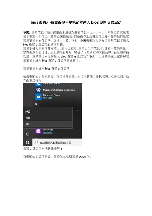
bios设置,小编告诉你三星笔记本进入bios设置u盘启动
导读:三星笔记本是目前市面上最受欢迎的笔记本之一,不少用户想要给三星笔记本重装一个自己中意的系统镜像包,但是操作之后发现自己并不懂的如何设置三星笔记本u盘启动,急得团团转。
下面,小编就来跟大家介绍三星笔记本进入bios设置u盘启动的操作步骤。
三星手机大家应该都知道,用的人比较多,三星也生产笔记本,拥有一流的质量、富有创意性的设计、加上漂亮的外观,吸引了很多朋友购买该品牌,很受用户的欢迎,三星笔记本如何进入bios设置u盘启动?下面,小编就来跟大家讲解三星笔记本进入bios设置u盘启动的操作了。
三星笔记本进入bios设置u盘启动
如果电脑处于关机状态,直接按开机键;如果电脑处于开机状态,点击电脑开始界面重启按钮。
设置u盘启动系统软件图解1
当电脑处于启动状态,屏幕显示电脑三星LOGO时,
bios系统软件图解2 按下F2键。
三星系统软件图解3 电脑进入Bios界面。
bios系统软件图解4
按电脑方向键右键,把页面切换到BOOT页面,然后按上下键移动到想要设置为启动位置的U盘上,按F5把位置移动到第一位,表示设置为第一数据读取地址。
设置u盘启动系统软件图解5
然后按右键把页面移动到Exit,再选中Exit Saving Changes ,之后按下回车键,即可把电脑设置为U盘启动。
bios系统软件图解6
以上就是三星笔记本进入bios设置u盘启动的操作方法。
如果大家在用u盘装系统的时候不懂设置u盘启动的话,可以按照上述步骤进行操作。
- 1、下载文档前请自行甄别文档内容的完整性,平台不提供额外的编辑、内容补充、找答案等附加服务。
- 2、"仅部分预览"的文档,不可在线预览部分如存在完整性等问题,可反馈申请退款(可完整预览的文档不适用该条件!)。
- 3、如文档侵犯您的权益,请联系客服反馈,我们会尽快为您处理(人工客服工作时间:9:00-18:30)。
12
警告
未能遵循标有此符号的下列说明可能会造成人身伤害,甚至会造成死亡。
电池使用方面
将电池放在婴儿和动物触及不到 的位置,因为它们可能会误吞 电池。 存在电击或窒息的危险。
不要在被褥、枕头或衬垫等通风 不良的地方使用计算机,而且不 要在有楼板暖气的房间等地方 使用,因为这样可导致计算机 过热。 注意不要堵塞计算机通风口 (位于一侧),在上述环境下 尤其如此。如果通风口堵塞, 计算机可能会过热,而且可能 导致计算机出现问题,或者甚 至发生爆炸。
Windows,也不提供 Windows。
x 用户需另外购买并安装正版
Windows XP/Windows Vista/Windows 7 之后才可使用本产 品。在其他产品上使用过,或者是非正版的 Windows XP/Windows Vista/Windows 7,可能 无法安装使用。
c 对于非三星笔记本提供的所有操作系统和软件的安装使用的问题,请与相关软件公司咨询。 v 不可因上述 x、c
16
警告
未能遵循标有此符号的下列说明可能会造成人身伤害,甚至会造成死亡。
关于存放和移动
在相关区域(如机场、医院等)使 用无线通信设备(无线 LAN、蓝 牙等)时,请遵循相关说明进行 操作。
当笔记本电脑和电源适配器、 鼠标、书籍等物品装在一起携 带时,请注意不要挤压笔记本 电脑。 如果较重的物体挤压笔记本电 脑,LCD 上可能会留下白点或 划痕。 因此,请小心携带,不要挤压 笔记本电脑。 在这种情况下,请将笔记本电 脑放与其他物体隔开放置。
SAMSUNG P428/R428/R429/R439/R478
用户指南
目录
第 1 章. 开始使用
有关其他支持的操作系统的注意事项 开始之前 安全注意事项 操作计算机的正确姿势 重要安全信息 更换零件和配件 法规符合性声明 WEEE 符号信息 中国环境标志产品认证信息 基本部件 概览
不要在浴室或桑拿室等潮湿地方 使用计算机。 计算机可能无法正常工作,而 且存在电击危险。 请在建议的温度和湿度范围 (10~32℃,20~80% RH)内使 用计算机。
认可的部件 请只使用认可的电池和交流电适 配器。 请只使用三星电子认可的电池 和适配器。 未经认可的电池和适配器可能 不符合合适的安全要求,而且 可能导致问题或故障,以及发 生爆炸或火灾。 关闭电源
文字表示法
图标
表示法 开始之前
说明 此部分中的内容包括使用某项功能前所需了解的信息。
注意
此部分中的内容包括所需了解的有关某项功能的信息。
参考
此部分中的内容包括使用该功能所需了解的有益信息。
版权
© 2009 三星电子。 本手册的版权属于三星电子。 未经三星电子同意,不得以任何形式或手段(电子或手工方式)复制或传播本手册的任何部分。 此文档中的信息可能会因改进产品性能而在未发出通知的情况下受到更改。 三星电子数据丢失不属于三星电子责任范围。请注意防止丢失重要数据,并备份数据以防丢失此 类数据。
避免身体的任何部位长时间遭受 打开的计算机通风孔或 AC 适配 器所释放热量的影响。 身体的部位长时间遭受通风口 或 AC 适配器所释放热量的影 响可能会导致烧伤。
将塑料袋子放在儿童触及不到的 位置。 否则,将有窒息的危险。
不要将计算机安装在斜面上或容 易震动的地方,或者避免在类似 位置上长时间使用计算机。 这样增加了发生故障或产品损 坏的风险。
用。 的原因要求退款或更换产品。如要求提供服务,需另行支付一定费
购买本产品之后,在第一次使用前,请把电池充足电。
开始之前
请先查看以下信息,然后再阅读本用户指南。
安全注意事项表示法
图标 表示法 警告 说明 未能遵循标有此符号的说明可能会造成人身伤害或死亡。
注意
未能遵循标有此符号的说明可能会造成轻度人身伤害或财产损失。
57 59 60
第 3 章. 设置和升级
LCD 亮度控制 BIOS 设置程序
进入 BIOS 设置程序 BIOS 设置程序屏幕
62 63
63 64
设置引导密码 更改引导优先级 电池
安装/卸下电池 对电池进行充电 测量剩余电池电量 延长电池使用时间
66 68 69
69 70 70 71
打开计算机
安装电池 连接AC适配器 打开计算机
48
48 48 49
省电模式使用指南
50
使用安全锁端口
72
第 4 章. 附录
产品规格 74
第 1 章 开始使用
有关其他支持的操作系统的注意事项 开始之前 安全注意事项 操作计算机的正确姿势 重要安全信息 更换零件和配件 法规符合性声明 WEEE 符号信息 中国环境标志产品认证信息 基本部件 概览
当计算机仍然打开时,不要关 闭 LCD 面板并将其放入包中进 行搬运。 如果在未关闭计算机的情况下 将其放入包中,计算机可能会 过热,而且存在火灾危险。请 在搬运前正确关闭计算机。
13
警告
未能遵循标有此符号的下列说明可能会造成人身伤害,甚至会造成死亡。
首 次使用计算机前,请 将电池充满电。
切勿加热电池或将电池放入火 中。不要在桑拿室、受热的车 辆内等炎热的地方放置或使用 电池。 存在爆炸或火灾危险。
在床上或衬垫上使用计算机时, 避免堵塞计算机底部或侧部的通 风孔。 如果通风孔堵塞,会存在损害 计算机或导致计算机内部过热 的危险。
NP Ver 2.3
警告
未能遵循标有此符号的下列说明可能会造成人身伤害,甚至会造成死亡。
关于电源
电源插头和壁装电源插座符号可能会因国家、地区、规格和产品型号的不同而有所不同。
如果电池液体泄漏或者电池散发 异味,请从计算机取出电池,然 后与服务中心联系。 存在爆炸或火灾危险。
注意不要让钥匙或夹子等金属物 体接触电池终端(金属部件)。 如果金属物体接触电池终端, 可能会导致过电流,而且可能 损坏电池,或者引起火灾。
要安全使用计算机,请用新的、 经认可的电池替换旧电池。
14
警告
不要使用损坏的或出现松动的市 电插座、电源线或电源插座。 存在电击或火灾的危险。
不要在拔出电源线时仅拉动电缆 本身。 如果电源线损坏,可能会造成标有此符号的下列说明可能会造成人身伤害,甚至会造成死亡。
不要过分弯折电源线,也不要 在电源线上放置重物。特别要 注意将电源线放在婴儿和动物 触及不到的位置。 如果电源线损坏,可能会造 成电击或火灾。
如果水或其他物质进入电源输 入插口、交流电适配器或计算 机,请断开电源线的连接,联 系服务中心寻求支持。 计算机内部设备的损坏可能 会造成电击或火灾。
将电源线连接到插座或带有接 地终端的多功能电源插座(延 长电缆)。 否则可能遭受电击。
保持电源线或插座清洁,没有 覆盖灰尘。 否则可能遭受电击。
11
警告
关于储存产品容量表示标准
关于硬盘容量表示 制造商计算存储设备(硬盘、固态磁盘(SSD))的容量时认为 1KB=1,000 字节。 但操作系统 (Windows) 计算存储设备容量时却认为 1KB=1,024字节,因此显示在 Windows 中的 硬盘容量会由于容量计算方法的差异而小于实际容量。(例如,对于 80GB 硬盘,Windows 将其 容量显示为 74.5GB, 80x1,000x1,000x1,000 字节/(1,024x1,024x1,024)字节 = 74.505GB) 此外,显示在 Windows 中的容量甚至可能会更小,因为某些还原解决方案之类的程序可能会驻留 在硬盘的隐藏区域。 关于内存容量表示 Windows 中所报告的内存容量小于实际内存容量。 这是因为 BIOS 或视频适配器占用了部分内存,或者占用内存供接下来使用。 (例如,对于安装的 1GB(=1,024MB) 内存,Windows 将容量报告为 1,022MB 或更小)
避免将磁盘驱动器暴露在磁场。 带有磁场的安全设施包括机场 使用的各种设备和安全棒。 检 查随身携带的行李的机场安检 设施,如输送带,使用 X 射线 而不用磁力,这样不会损坏驱 动器。
17
注意
未能遵循标有此符号的下列说明可能会造成轻微人身伤害,或者可能会损坏产品。
关于安装
不要堵塞产品的各个端口(各种 孔)、通风孔等,注意不要插 入异物。 计算机内部组件的损坏可能会 造成电击或火灾。 当计算机侧放使用时,请保持 开有通风孔的一侧向上。 否则,可能会造成计算机内部 温度上升,引起计算机故障 或停机。 不要在本产品上放置重物。 这样可能会造成计算机出现问 题。另外,物品可能会跌落, 引起人身伤害,或者可能会损 坏计算机。
前视图 状态指示灯 右视图 左视图 后视图 底视图
第 2 章. 使用计算机
6 7 9 22 25 27 30 40 41 42 43
43 44 45 46 47 47
键盘 触摸板 CD 驱动器 (ODD, 可选)
插入和弹出 CD
52 55 56
56
多卡插槽 (可选) Express 卡插槽 (可选) 调节音量
当取出 RTC (实时时钟) 的电 池时,将电池放在儿童触及不到 的位置,因为他们可能会触摸 和/或误吞电池。 否则,将有窒息的危险。如果 儿童误吞电池,请立即联系 医生。
禁止私自拆卸计算机,如需升级 内存或硬盘需咨询当地的三星维 修站并由维修站实施升级(如 客户自行升级内存或硬盘后, 导致的计算机故障不在保修范 围内)。
长时间使用笔记本 PC 时,不 要将身体的某一部分直接与其接 触。在正常操作期间,产品的温 度可能会升高。 这会导致伤害或灼伤皮肤。
15
警告
未能遵循标有此符号的下列说明可能会造成人身伤害,甚至会造成死亡。
关于升级
切勿拆卸交流电适配器和计算 机外壳! 存在电击的危险。