【机械类文献翻译】步进电机和伺服电机的系统控制
伺服电机与步进电机的工作原理和六大区别
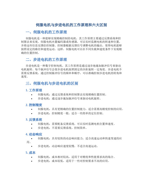
伺服电机与步进电机的工作原理和六大区别一、伺服电机的工作原理伺服电机是一种能够实现精确控制的电机,其工作原理主要通过反馈系统和控制算法来实现。
伺服电机内置编码器或传感器,可以实时监测电机的转速和位置,并将这些信息反馈给控制器。
控制器根据反馈信号调整电机的输出,使得电机能够按照设定的路径和速度运动。
这样,伺服电机可以在不同负载和速度条件下实现精确的位置控制。
二、步进电机的工作原理步进电机是一种数字控制电机,其工作原理是通过逐步地施加脉冲信号来驱动电机旋转。
每个脉冲信号会使步进电机按照固定的步距旋转一定角度。
步进电机不需要反馈系统,通过控制脉冲信号的频率和顺序,可以准确控制步进电机的转角和速度。
三、伺服电机与步进电机的区别1. 工作原理•伺服电机:通过反馈系统和控制算法实现精确位置控制。
•步进电机:通过逐步施加脉冲信号来驱动电机旋转。
2. 控制精度•伺服电机:具有更精确的位置控制能力,适合需要高精度控制的应用。
•步进电机:控制精度一般,适合一些简单的定位控制。
3. 反馈系统•伺服电机:需要配备反馈系统,可以实时监测电机位置和速度。
•步进电机:不需要反馈系统,控制简单。
4. 动态响应•伺服电机:具有较快的动态响应能力,适合高速运动和快速变速的应用。
•步进电机:动态响应速度较慢,不适合高速运动。
5. 成本•伺服电机:成本相对较高,适用于对精度和性能要求高的场合。
•步进电机:成本较低,适用于一些对控制要求不高的应用。
6. 使用场景•伺服电机:适用于需要高精度、高速度和高性能的自动化设备。
•步进电机:适用于一些简单的定位控制、打印机、CNC机床等领域。
综上所述,伺服电机和步进电机在工作原理、控制精度、反馈系统、动态响应、成本和使用场景等方面存在明显的区别,应根据具体需求来选择合适的电机类型。
步进伺服毕业论文
步进伺服毕业论文引言计算机控制技术是现代制造业中最重要的技术之一,步进伺服控制技术作为其中的一个重要分支,已经成为机械制造、电子工业等领域的重要基础技术。
本文主要介绍了步进伺服控制技术的相关知识,包括步进电机的工作原理、伺服系统的工作原理、步进伺服控制系统的组成以及步进伺服控制系统的运行等方面。
结合实际应用,分析了步进伺服控制技术在现代制造业中的应用和发展趋势。
一、步进电机的工作原理步进电机是一种特殊的电动机,具有按步旋转的特点,其每一步转动角度精度可以达到很高。
步进电机的工作原理是基于磁力学原理的,将电能转化为机械能。
步进电机的转子是由一个或多个永磁体组成,旋转时通过交替的通电方式,可使得电机中产生一个磁场,该磁场与转子上的磁场相互作用,从而使得转子产生旋转。
步进电机转动的每一步都是由电脉冲驱动的,每一次电脉冲的信号会让转子转过一个固定的角度。
因此,步进电机可以准确地控制输出转速和位置。
二、伺服系统的工作原理伺服系统是一种自动控制系统,通过对系统的反馈控制实现对位置、速度、力、角度等物理量的控制。
伺服系统主要由传感器、执行器、控制器和反馈机构等部分组成。
其中,传感器用来检测系统中的位置、角度、速度等基本物理量,反馈控制器利用传感器的反馈信息来实现自动控制,执行器将控制信号转化为具体的动作,反馈机构用于对执行器的动作进行检测,从而实现对系统的闭环控制。
三、步进伺服控制系统的组成步进伺服控制系统是将步进电机和伺服系统相结合而成的,其工作原理是通过伺服系统的反馈机制来实现对步进电机的控制。
步进伺服控制系统的组成主要包括步进电机、编码器、控制器和驱动电路等部分。
步进电机:步进电机是步进伺服控制系统的核心部分,负责转动电机的旋转角度。
由于步进电机的控制精度很高,因此可实现精确的位置控制和速度调节,广泛应用于驱动自动化机械和设备的领域中。
编码器:编码器是用来检测步进电机转动角度的装置,其主要作用是将电机的转动信息转化为数字信号,供控制器进行处理。
伺服电机与步进电机控制的区别详解

伺服电机与步进电机控制的区别详解1,步进电机原理步进电机作为控制用的特种电机,是将电脉冲转化为角位移的执行机构。
当步进驱动器接收到一个脉冲信号,它就驱动步进电机按设定的方向转动一个固定的角度(称为“步距角”),它的旋转是以固定的步进角度一步一步运行的。
可以通过控制脉冲个数来控制角位移量,从而达到准确定位的目的;同时可以通过控制脉冲频率来控制电机转动的速度和加速度,从而达到调速的目的,改变绕组的通电顺序,电机就会反转。
驱动器原理步进电机需要使用专用的步进电机驱动器驱动,驱动器由脉冲发生控制单元、功率驱动单元、保护单元等组成。
功率驱动单元将脉冲发生控制单元生成的脉冲放大,与步进电机直接耦合,属于步进电机与微控制器的功率接口。
控制指令单元,接收脉冲与方向信号,对应的脉冲发生控制单元对应生成一组相应相数的脉冲,经过功率驱动单元后送到步进电机,步进电机在对应方向上转过一个步距角。
驱动器的脉冲给定方式决定了步进电机运行方式,如下:(1)m相单m拍运行(2)m相双m拍运行(3)m相单、双m拍运行(4)细分驱动,需要驱动器给出不同幅值的驱动信号步进电机有一些重要的技术数据,如最大静转矩、起动频率、运行频率等。
一般来说步距角越小,电机最大静转矩越大,则起动频率和运行频率越高,所以运行方式中强调了细分驱动技术,该方式提高了步进电机的转动力矩和分辨率,完全消除了电机的低频振荡。
所以细分驱动器驱动性能优与其他类型驱动器。
伺服电机内部的转子是永磁铁,驱动器控制的进行比较,调整转子转动的角度。
2,伺服电机伺服电机原理伺服电动机又称执行电动机,在自动控制系统中,用作执行元件,把所收到的电信号转换成电动机轴上的角位移或角速度输出。
分为直流和交流伺服电动机两大类。
伺服电机接收到1个脉冲,就会旋转1个脉冲对应的角度,从而实现位移,因为,伺服电机本身具备发出脉冲的功能,所以伺服电机每旋转一个角度,都会发出对应数量的脉冲,这样,和伺服电机接受的脉冲形成了闭环,系统就会知道发了多少脉冲给伺服电机,同时又收了多少脉冲回来,这样,就能够很精确的控制电机的转动,从而实现精确的定位。
伺服电机及其控制原理

伺服电机及其控制原理伺服电机是一种能够根据外部控制信号来实现准确位置控制的电动机。
它通过搭配编码器或传感器,能够反馈运动信息,实现高精度的运动控制。
伺服电机广泛应用于机器人、自动化设备、工业生产线以及医疗仪器等领域。
伺服电机的工作原理可以简单描述为:通过控制器将目标位置和当前位置进行比较,计算出位置偏差,并通过电机驱动器控制电机旋转,使得位置偏差最小化,从而实现精确的位置控制。
通常情况下,伺服电机控制系统由以下几个主要组成部分构成:1.电机:伺服电机通常采用直流电机或交流电机,有时也会采用步进电机。
电机的类型和规格取决于具体的应用需求。
2.编码器或传感器:它们负责检测电机的位置或运动状态,并将这些信息反馈给控制器。
编码器可以采用不同的工作原理(如光电式、磁电式等),用于提供高精度的位置反馈。
3.控制器:控制器是伺服系统的核心部件,其功能是接收来自外部的指令信号,并输出给电机驱动器。
控制器通常采用微处理器或数字信号处理器(DSP)来实现控制算法,并与编码器/传感器配合使用,实现位置反馈和误差校正。
4.电机驱动器:电机驱动器负责将来自控制器的指令信号转化为电流或电压输出,控制电机的旋转。
电机驱动器通常包含功率放大器、保护电路和信号转换电路等部分。
伺服电机的控制原理基于闭环反馈控制的思想,主要包括位置控制和速度控制两个方面。
对于位置控制,控制器将目标位置与当前位置进行比较,并计算出位置误差。
根据误差大小和方向,控制器调整输出信号,通过电机驱动器控制电机的旋转,使得位置误差最小化。
位置反馈信号由编码器或传感器提供,控制器通过比较反馈信号和目标位置来实现闭环控制。
对于速度控制,控制器将目标速度与当前速度进行比较,并计算速度误差。
根据误差大小和方向,控制器调整输出信号,通过电机驱动器控制电机的转速,使得速度误差最小化。
速度反馈信号通常由编码器或传感器提供,控制器通过比较反馈信号和目标速度来实现闭环控制。
在实际应用中,伺服电机控制系统还需要考虑加速度、阻尼等因素,以实现更加精确的运动控制。
(完整word版)伺服电机外文文献翻译

伺服电机1。
伺服电机的定义伺服电动机又称执行电动机,在自动控制系统中,用作执行元件,把所收到的电信号转换成电动机轴上的角位移或角速度输出。
分为直流和交流伺服电动机两大类,其主要特点是,当信号电压为零时无自转现象,转速随着转矩的增加而匀速下降.伺服电机在伺服系统中控制机械元件运转的发动机。
是一种补助马达间接变速装置。
伺服电机可使控制速度,位置精度非常准确。
将电压信号转化为转矩和转速以驱动控制对象。
转子转速受输入信号控制,并能快速反应,在自动控制系统中作执行元件,且具有机电时间常数小、线性度高、始动电压低等特点.2。
伺服电机工作原理1。
伺服主要靠脉冲来定位,基本上可以这样理解,伺服电机接收到1个脉冲,就会旋转1个脉冲对应的角度,从而实现位移,因为,伺服电机本身具备发出脉冲的功能,所以伺服电机每旋转一个角度,都会发出对应数量的脉冲,这样,和伺服电机接受的脉冲形成了呼应,或者叫闭环,如此一来,系统就会知道发了多少脉冲给伺服电机,同时又收了多少脉冲回来,这样,就能够很精确的控制电机的转动,从而实现精确的定位,可以达到0。
001mm.有刷电机成本低,结构简单,启动转矩大,调速范围宽,控制容易,需要维护,但维护方便(换碳刷),产生电磁干扰,对环境有要求.无刷电机体积小,重量轻,出力大,响应快,速度高,惯量小,转动平滑,力矩稳定。
控制复杂,容易实现智能化,其电子换相方式灵活,可以方波换相或正弦波换相。
电机免维护,效率很高,运行温度低,电磁辐射很小,长寿命,可用于各种环境.2。
交流伺服电机也是无刷电机,分为同步和异步电机,目前运动控制中一般都用同步电机,它的功率范围大,可以做到很大的功率.大惯量,最高转动速度低,且随着功率增大而快速降低。
因而适合做低速平稳运行的应用.3。
永磁交流伺服电动机简介20世纪80年代以来,随着集成电路、电力电子技术和交流可变速驱动技术的发展,永磁交流伺服驱动技术有了突出的发展,各国著名电气厂商相继推出各自的交流伺服电动机和伺服驱动器系列产品并不断完善和更新。
文献翻译(伺服系统中英文翻译)

武汉轻工大学毕业设计(论文)外文参考文献译文本2014届原文出处指导老师给出毕业设计(论文)题目PMSM伺服系统---MATLAB仿真设计院(系)电气与电子工程学院专业名称自动化学生姓名陈思明学生学号100408903指导教师高峰译文要求:1、译文内容须与课题(或专业)有联系;2、外文翻译不少于4000汉字。
SERVO CONTROL SYSTEMS 1: DC ServomechanismsElke Laubwald: Visiting Consultant, control systems ABSTRACT: This is one of a series of white papers on systems modelling, analysis and control, prepared by Control Systems to give insights into important principles and processes in control. In control systems there are a number of generic systems and methods which are encountered in all areas of industry antechnology. These white papers aim to explain these important systems and methodsinstraightforward terms.The white papers describe what makes a particular type of system/method important, how it works and then demonstrates how to control it. The control demonstrations is performed using models of real systems designed by our founder - Peter Wellstead, and developed for manufacture by TQ Education and Training Ltd in their CE range of equipment. Where possible results from the real system are shown. This white paper is about the universally used ‘work horse’ of electro-mechanical systems– the DC servo control system or servomechanism.1. What is a Servo Control System and servo motor?A servo control system is one of the most important and widely used forms of control system. Any machine or piece of equipment that has rotating parts will contain one or more servo control systems. The job of the control system may include:Maintaining the speed of a motor within certain limits, even when the load on the output of the motormight vary. This is called regulation.Varying the speed of a motor and load according to an externally set programme of values. This is called set point (or reference) tracking.Our daily lives depend upon servo controllers. Anywhere that there is an electric motor there will be a servo control system to control it. Servo control is very important. The economy of the world dependsupon servo control (there are other things to be sure – but stay with me on the control theme). Manufacturing industry would cease without servo systems because factory production lines could not becontrolled, transportation would halt because electric traction units would fail, computers would cease because disk drives would not work properly and communications networks would fail because network servers use hard disk drives. Young people would become even more unbearable and they would complain more than they do now, because their music and games systems will not work without servo control.Servo control systems are that important and it is vital to know about them. So pay attention and sit up straight – you are not on holiday and I am not writingthis for the good of my health.Also known as the implementation of the motor servo motor, the automatic control system for the implementation of components to convert signals received from the motor shaft angular displacement or angular velocity output.DC and AC servo motor is divided into two categories, the main feature is that when the signal voltage is zero, no rotation of the phenomenon, the increasing speed with uniform torque decreased.Servo motors to control mechanical servo system in the operation of the engine components. Is a servomotors device.Servo motor can control the speed, position accuracy is very accurate.The voltage signal into a torque and speed to drive the control object.Rotor speed by the input signal control, and can respond rapidly, in the automatic control system for the implementation of components, and has electrical and mechanical time constant, linear and high initiating voltage low.2. Modelling a Simple Servo SystemBefore we can control a system we must understand in mathematical terms how the system behaves without control. This is system modelling and it is a fundamental part of our work in control systems analysis. This white paper is about the simplest form of servo – the direct current (DC) position control servomechanism. It is important because, although it is the simplest form of servomechanism, it is usedas the starting point for understanding all other servo systems The basic form of a DC servo system is made of an electric motor with an output shaft that has an inertialload J on it, and friction in the bearings of the motor and load (represented by the constant b). There will be an electric drive circuit where an input voltage u(t) is transformed by the motor into a torque T(t) inthe motor output shaft. Using systems modelling ideas for mechanical systems a torque balance can bewritten between the input torque from the motor and the torque required to accelerate the load and overcome friction. This is shown in the equation()J b T t θθ+=Where θ is the angular position of the servo output shaft. The control objective is to control the shaft Position or the shaft velocity to be some desire value . The input voltage u(t) is related to the torque T(t) a gain K and the inertia divided by the friction coefficient is referred to as the system time constant ⎜ , where τ=J/b So the system model becomes:+()Ku t τθθ=In a practical servo system there will be additional components of the model which are important. Many of these are to do with the nonlinearities in the drive amplifier and friction in the mechanical components. The most important nonlinearities are the saturation voltage of the motor drive amplifier, the deadband in the amplifier, the so-called Coulomb friction in the rotating mechanical components andhysteresis (backlash) in any gearboxes that might be between the motor and the load. A good control system must include features to deal with these nonlinear features.In this white paper we will concentrate on the linear parts of the servo system and only show some hints of non-linear issues. The linear part of the servo system model can be put in the transfer function form:()()()1K Y s U s s s τ=+ Where y(s ) is the output shaft position and u(s) is the motor input. K is the system gain and τ is tthe time constant.An important job for the control systems analyst is to know how to measure the values of the gains K and the time constant . To make it easier to follow in this case we can say that for example, the CE110 Servo Trainer has been designed to give a gain of one between the motor input and the motor speed, and anapproximate gain of K = 2 between the measured speed and the measured shaft position. The nominal value of the time constant is 1.5. So the transfer function model can be decomposed into the transfer function from the motor input to the motor speed v(s), an d the transfer function from the motor speed to the output shaft position.()1()(s)1()()v s U s kU s Y s s τ=+=Many control systems design tools use a state space representation of the system model. In servo systems the states are the velocity and position of the servo system output shaft. Rearranging the system transfer model gives the state space form:Also note that the servo system measured variables in the state model are the position of the shaft y (using a position encoder or potentiometer) and the velocity v (using a speed encoder). The linear models given above are the basis of the design of servo controllers. A real servo however has non-linear components that influence its dynamic behaviour. The main nonlinearities are Coulombfriction in the moving parts and the dead zone and saturation in the motor input amplifier. This is advanced control and we will not cover it in this white paper.Servo mainly rely on impulse to locate, basically can be understood, the servo motor receives a pulse, a pulse will rotate the corresponding point of view, in order to achieve the displacement, because the servo motor itself has issued a pulse function, so the servoEach motor to rotate a point of view, is issued by the corresponding number of pulses, so that the pulse and servo motors to accept the formation of the echo, or called closed-loop, this way, the system will know the number of pulses sent to the servo motor, while the number of receivedpulse came back, so that we can very accurately control the motor rotation, in order to achieve accurate positioning, can reach 0.001mm.DC servo motor into brush and brushless motors.Brush motor low cost, simple structure, starting torque, wide speed range, easy control, need to maintain, but easy to maintain (replacement carbon brushes), generate electromagnetic interference, the environment requirements.So it can be used for cost-sensitive general industrial and civil applications.Brushless motor, small size, light weight, large output, fast response, high speed, small inertia, rotational smoothness, torque and stability.Control complex, easy to implement intelligent, flexible way of their electronic commutation, the commutation can be square wave or sinusoidal commutation.Motor maintenance-free, high efficiency, low operating temperature, electromagnetic radiation is very small, long-life, can be used for a variety of environments.Brushless AC servo motor is divided into synchronous and asynchronous motors, motion control in the current synchronous motor is generally used, and its power range, can do a lot of rge inertia, the maximum rotation speed is low, and with the power increases rapidly decreased.Thus suitable for applications that run on low speed steady. Servo motor rotor is permanent magnet, the drive control of the U / V / W three-phase power to form fields, the rotor in the magnetic field under the rotation, while the motor comes with encoder feedback signal to the drive, the drive according to the feedback valuecompared with the target value, adjusting the angle of the rotor rotation.Depends on the accuracy of the servo motor encoder accuracy (lines).Question:AC servo motors and brushless DC servo motor function, what is the difference? A: AC servo better because a sine wave control, torque ripple small.DC servo is a trapezoidal wave.But the DC servo is relatively simple, cheap3. Example of a Servo SystemThe figure 1 shows the CE110 Servo Trainer from TQ Education and Training Ltd. This is a classic andcomprehensive representation of the servo control problem. It contains all relevant features that can befound in a practical servo system. The centre section of the system are the main hardware elements, fromthe left they are:1. The inertial load2. The speed sensor3. An active load (in this case a generator, G)4. The servo motor, M5. An electric clutch and gearbox (can you see the picture of a gear system on the right?)6. And under the gear system is the output shaft with a position sensor.The electric clutch allow the position system to be disconnected to study velocity control problems. Thegearbox is included because servo mechanisms for position control very often havegearboxes to reducespeed and increase torque. The generator is included so that control under variable load can beinvestigated.At the top of the front panel are electronic versions of all the nonlinear elements that can be found in realservos – these are used to teach nonlinear compensation and to understand what to look for in practicalsituations. We will be using the linear motor with internal load and position output through a gearbox toillustrate servo control in action. I might show some nonlinear behaviour in this white paper, but thenagain, I might not – it depends on how nice you are to me as I sit on this keyboard, all the time dreamingof my beautiful mountain homeland and mein Verlobter.4. Servo System ControllersThere are many, many alternative controller design theories that can be used to control a servomechanism. Possibly there are too many. Here is a list of most of the techniques:1. Three term (PID) control2. Velocity Feedback Control3. Phase Lead Compensation4. State Feedback Control5. State Observer Implementation and Control6. Linear Quadratic Regulator (LQR)7. Linear Quadratic Gaussian (LQG)8. Robust Control9. Sliding Mode and Variable Structure Control10. Dead Beat ControlEach of the above can be implemented as a continous time method or a digital method based on Ztransforms. Also it is possible to use techniques such as fuzzy control and its variants. A bewilderingchoice is it not? And what is more, all of them can give an acceptable performance if designed with careand by an expert. For example, robust control potentially gives the best technicaland practical results, butan expert is required to select the design factors required and to get a simple implementable controller.5. Introduction permanent magnet AC servo motor80 years since the 20th century, with the integrated circuits, power electronics and AC variable speed drive technology, permanent magnet AC servo drive technology with outstanding development, national electrical manufacturers have launched their own well-known AC servo motor and servo drive seriesand continue to improveand update products.AC servo system has become a contemporary high-performance servo systems the main development direction, so that the original DC servo facing the crisis of being eliminated.90 years later, the world has been commercialized by AC servo digital control system is a sine wave motor servo drive.AC servo drive the rapid development of the field in thetransmission.Permanent magnet AC servo motor compared with DC servo motor, the main advantages are: ⑴without brush and commutator, it is reliable and maintenance requirements for maintenance and low.⑵cooling the stator winding more convenient.⑶inertia is small, easy-to improve the system fast.⑷adapted to high-speed high torque working condition.⑸under the same power, smaller size and weight.Since the German MANNESMANN of Rexroth Indramat division in the company's Hanover Trade Fair 1978 was officially launched MAC permanent magnet AC servo motor and drive system, which marks this new generation of AC servo technology has entered the practical stage.To the late 20th century, 80 years, the company has a complete line of products.The servo-device market are turning to the exchange system.Early analog systems such as zero-drift, interference, reliability, accuracy and flexibility in areas such as lack of motion control is still not fully meet the requirements, in recent years with the microprocessor, the new digital signal processor (DSP) applicationsthe emergence of digital control system, the control section can be carried out entirely by the software, called Jiang hazy or Tuan Shen Jing only fresh coarse hempen fabric, valiant only Shen of the permanent magnet AC servo system.So far, high-performance servo systems mostly use electrical permanent magnet synchronous AC servo motor, control the drive to use more fast, accurate positioning of the all-digital servo system.Typical manufacturers such as Siemens of Germany, the United States and Japan Kollmorgen companies such as Panasonic and Yaskawa.Yaskawa Electric has launched a small-scale production of AC servomotors and drives, in which D series for CNC machine tools (maximum speed of 1000r/min, torque is 0.25 ~ 2.8Nm), R series is suitable for the robot (the highest speed of 3000r/min, torque is 0.016 ~ 0.16Nm).Launched after the M, F, S, H, C, G six series.90 20th century, has introduced a new D-series and Rseries.Rectangular wave drive from the old series, 8051 to control the sine wave drive, 80C, 154CPU and gate array chip control, torque ripple from 24% to 7%, and improved reliability.Thus, the formation of only a few years, eight series (power range of 0.05 ~ 6kW) more complete system to meet the working machinery, transportation agencies, welding robots, assembly robots, electronic components, processing machinery, printing presses, high speed winding machine, winding machines for different C equipment to produce the famous Japanese law that g (Fanuc) company, in the 20th century has introduced the mid-80s S series (13 specifications), and L series (5 specifications) of the permanent magnet AC servo motor.L Series has a smaller moment of inertia and the mechanical time constant, particularly for applications that require fast response servo system.Other Japanese manufacturers, such as: Mitsubishi Motors (HC-KFS, HC-MFS, HC-SFS, HC-RFS and HC-UFS series), Toshiba Seiki (SM series), Okuma Iron Works (BL series), Sanyo Electric(BL series), standing stones motor (S series) and many other manufacturers have entered the permanent magnet AC servo system fray.Germany Rexroth (Rexroth) The MAC Indramat Division Series AC servo motor Total 7 Frame 92 specifications.Germany's Siemens (Siemens)'s IFT5 series three-phase permanent magnet AC servo motor standard and short form is divided into two categories, a total of 98 species of 8 frame size specifications.Allegedly the same series AC servo motor and DC servo motor output torque compared IHU series, which weighs only 1 / 2, supporting the transistor PWM drive 6SC61 series, the most for 6-axis motor control.Bosch (BOSCH) ferrite magnets produced the SD series (17 standard) and rare earth permanent magnet of the SE series (8 specs) AC servo motor and drive controller Servodyn SM series.American production companies Gettys servo device as Gould Electronics, once a division of (Motion Control Division), production ofM600 series A600 series AC servo motor and servo drives.After the merger to the AEG, Gettys name restored, the introduction of A700 all-digital AC servo system.U.S. AB (ALLEN-BRADLEY) 1326-based production company driver division ferrite permanent magnet AC servo motor and servo controller PWM AC 1391.Frame size motors including 3 of 30 specifications.ID (Industrial Drives) is a famous Cole Morgan (Kollmorgen) of industrial drives division, has produced BR-210, BR-310, BR-510 a total of 41 specifications of the three series of brushless servo motor and servo BDS3drive.Since 1989, launched a new series designedsolely doped Jian Pirates (Goldline) permanent magnet AC servo motor, including the B (small inertia), M (Middle Inertia) and EB (explosion proof) three categories, 10,20,40,60,80 five frame sizes, each of 42 categories of specifications, all using NdFeB permanent magnet, torque range of 0.84 ~ 111.2Nm, a power range of 0.54 ~ 15.7kW.Supporting the drive has BDS4 (analog), BDS5 (digital type, with position control) and the Smart Drive (digital type) of three series, the maximum continuous current of 55A.Goldline Series represents contemporary art in permanent magnet AC servo technology.Ireland's Inland formerly a division of Kollmorgen abroad, now merged into the AEG, the production of DC servo motors, DC torque motor and servo amplifier is known.Production BHT1100, 2200,3300 three frame sizes of 17 kinds of specifications of SmCo permanent magnet AC servo motor and eight controllers.French Alsthom Group factory in Paris Parvex LC series (long form) and GC series (short) 14 AC servo motor specifications, and production AXODYN series of drives.The former Soviet Union for the CNC machine tools and robots servo control developed two series of AC servo motor.One ДBy series uses ferrite magnets, there are two frame sizes, frame sizes are 3 for each core length, each with two winding data, a total of 12 specifications, a continuous torqu e range of 7 ~ 35N.m.2ДBy series uses rare earth permanent magnet, 6 frame size 17 specifications, the torque range is 0.1 ~170N.m, supporting the 3ДБ controller.In recent years, Panasonic has introduced the all-digital AC servo system based MINAS series, in which permanent magnet AC servo motor with MSMA series of small inertia-type, power from 0.03 ~ 5kW, a total of 18 kinds of specifications; the inertia type with MDMA, MGMA, MFMA threeseries, the power from 0.75 ~ 4.5kW, 23 kinds of specifications, MHMA series of large inertia motor power range from 0.5 ~ 5kW, 7 kinds of specifications.Samsung developed in recent years, all-digital AC servo motor and drive system, which FAGA AC servo motor series of CSM, CSMG, CSMZ, CSMD, CSMF, CSMS, CSMH, CSMN, CSMX a variety of models, the power from 15W ~ 5kW.Now often used (Powerrate) This comprehensive index as the servo motor quality factor, measuring a variety of AC and DC servo motor contrast and dynamic response performance stepper motor.Continuous motor power, said the rate of change (rated) torque and rotor inertia ratio.Change rate is calculated by power analysis, the permanent magnet AC servo motor technology indicators for the United States ID, Goldline Series is the best, followed by Germany's Siemens in IFT5 series.摘要:这是根据控制系统理论撰写的关与系统模型、分析和控制的一系列白皮书之一,目的在于给出一些重要的控制理论和控制过程。
步进电机与伺服电机控制的区别
步进电机与伺服电机控制的区别步进电机的控制系统由可编程控制器、环行脉冲分配器和步进电机功率驱动器组成,控制系统中plc用来产生控制脉冲;通过plc编程输出一定数量的方波脉冲,控制山社步进电机的转角进而控制伺服机构的进给量;同时通过编程控制脉冲频率就是伺服机构的进给速度,环行脉冲分配器将可编程控制器输出的控制脉冲按步进电机的通电顺序分配到相应的绕组。
PLC控制的步进电机可以采用软件环行分配器,也可以采用硬件环行分配器。
采用软环占用的PLC资源较多,特别是步进电机绕组相数M>4时,对于大型生产线应该予以充分考虑。
采用硬件环行分配器,虽然硬件结构稍微复杂些,但可以节省占用PLC的I/O口点数。
一般PLC的输出接口具有一定的驱动能力,而通常的晶体管直流输出接口的负载能力仅为十几—几十伏特、几十—几百毫安;但对于功率步进电机则要求几十—上百伏特、几安—十几安的驱动能力,因此应该采用驱动器对输出脉冲进行放大。
伺服机构的步进电机无脉冲输入时便停止运转,伺服执行机构定位。
当伺服执行机构的位移速度要求较高时,可以用PLC中的高速脉冲发生器。
不同的PLC其高速脉冲的频率可达4000—6000Hz。
对于自动线上的一般伺服机构,其速度可以得到充分满足。
如伺服机构采用硬件环行分配器,则占用PLC的I/O口点数少于5点,一般仅为3点。
其中I口占用一点,作为启动控制信号;O口占用2点,一点作为PLC的脉冲输出接口,接至伺服系统硬环的时钟脉冲输入端,另一点作为山社步进电机转向控制信号,接至硬环的相序分配控制端。
伺服系统采用软件环行分配器时,将PLC控制的开环伺服机构用于某大型生产线的数控滑台,每个滑台仅占用4个I/O接口,节省了CNC控制系统,其脉冲当量为0.01~0.05mm,进给速度为Vf=3~15m/min,完全满足工艺要求和加工精度要求。
【资料】步进电机和伺服电机的系统控制中英文翻译资料

【关键字】资料SELECTING THE MOTOR THAT SUITS YOUR APPLICATION Motion control, in its widest sense, could relate to anything from a welding robot to the hydraulic system in a mobile crane. In the field of Electronic Motion Control, we are primarily concerned with systems falling within a limited power range, typically up to about 10HP (7KW), and requiring precision in one or more aspects. This may involve accurate control of distance or speed, very often both and sometimes other parameters such as torque or acceleration rate. In the case of the two examples given, the welding robot requires precise control of both speed and distance; the crane hydraulic system uses the driver as the feedback system so its accuracy varies with the skill of the operator. This wouldn’t be considered a motion control system in the strict sense of the term. Our standard motion control system consists of three basic elements:Fig. 1 Elements of motion control systemThe motor,This may be a stepper motor (either rotary or linear), a DC brush motor or a brushless servo motor. The motor needs to be fitted with some kind of feedback device unless it is a stepper motor.Fig. 2 shows a system complete with feedback to control motor speed. Such a system is known as a closed-loop velocity servo system.Fig. 2 Typical closed loop (velocity) servo systemThe drive,this is an electronic power amplifier that delivers the power to operate the motor in response to low-level control signals. In general, the drive will be specifically designed to operate with a particular motor type –you can’t use a stepper drive to operate a DC brush motor, for instance.Application Areas of Motor TypesStepper MotorsStepper Motor BenefitsStepper motors have the following benefits:• Low cost• Ruggedness• Simplicity in construction• High reliability• No maintenance• Wide acceptance• No tweaking to stabilize• No feedback components are needed• They work in just about any environment• Inherently more failsafe than servo motors.There is virtually no conceivable failure within the stepper drive module that could cause the motor to run away. Stepper motors are simple to drive and control in an open-loop configuration. They only require four leads. They provide excellent torque at low speeds, up to 5 times the continuous torque of a brush motor of the same frame size or double the torque of the equivalent brushless motor. This often eliminates the need for a gearbox. A stepper-driven-system is inherently stiff, with known limits to the dynamic position error.Stepper Motor DisadvantagesStepper motors have the following disadvantages:• Resonance effects and relatively long settling times• Rough performance at low speed unless a micro step drive is used• Liability to undetected position loss as a result of operating open-loop• They consume current regardless of load conditions and therefore tend to run hot• Losses at speed are relatively high and can cause excessive heating, and they are frequently noisy (especially at high speeds).• They can exhibit lag-lead oscillation, which is difficult to damp. There is a limit to their available size, and positioning accuracy relies on the mechanics (e.g., ball screw accuracy). Many of these drawbacks can be overcome by the use of a closed-loop control scheme. Note: The Comp motor Zeta Series minimizes or reduces many of these different stepper motor disadvantages. There are three main stepper motor types:• Permanent Magnet (P.M.) Motors• Variable Reluctance (V.R.) Motors• Hybrid MotorsWhen the motor is driven in its full-step mode, energizing two windings or “phases” at a time (see Fig. 3), the torque available on each step will be the same (subject to very small variations in the motor and drive characteristics). In the half-step mode, we are alternately energizing two phases and then only one as shown in Fig. 4. Assuming the drive delivers the same winding current in each case, this will cause greater torque to be produced when there are two windings energized. In other words, alternate steps will be strong and weak. This does not represent a major deterrent to motor performance—the available torque is obviously limited by the weaker step, but there will be a significant improvement in low-speed smoothness over the full-step mode.Clearly, we would like to produce approximately equal torque on every step, and this torque should be at the level of the stronger step. We can achieve this by using a higher current level when there is only one winding energized. This does not over dissipate the motor because the manufacturer’s current rating assumes two phases to be energized the current rating is based on the allowable case temperature). With only one phase energized, the same total power will be dissipated if the current is increased by 40%. Using this higher current in the one-phase-on state produces approximately equal torque on alternate steps (see Fig. 5).Fig. 3 Full step currentFig. 4 Half step currentFig.5 Half step current, profiledWe have seen that energizing both phases with equal currents produces an intermediate step position half-way between the one-phase-one positions. If the two phase currents are unequal, the rotor position will be shifted towards the stronger pole. This effect is utilized in the micro stepping drive, which subdivides the basic motor step by proportioning the current in the two windings. In this way, the step size is reduced and the low-speed smoothness is dramatically improved. High-resolution micro step drives divide the full motor step into as many as 500 micro steps, giving 100,000 steps per revolution. In this situation, the current pattern in the windings closely resembles two sine waves with a 90°phase shift between them (see Fig. 6). The motor is now being driven very much as though it is a conventional AC synchronous motor. In fact, the stepper motor can be driven in this way from a 60 Hz-US (50Hz-Europe) sine wave source by including a capacitor inseries with one phase. It will rotate at 72 rpm.Fig. 6 Phase currents in micro step modeStandard 200-Step Hybrid MotorThe standard stepper motor operates in the same way as our simple model, but has a greater number of teeth on the rotor and stator, giving a smaller basic step size. The rotor is in two sections as before, but has 50 teeth on each section. The half-tooth displacement between the two sections is retained. The stator has 8 poles each with 5 teeth, making a total of 40 teeth (see Fig. 7).Fig.7 200-step hybrid motorIf we imagine that a tooth is placed in each of the gaps between the stator poles, there would be a total of 48 teeth, two less than the number of rotor teeth. So if rotor and stator teeth are aligned at 12 o’clock, they will also be aligned at 6 o’clock. At 3 o’clock and 9 o’clock the teeth will be misaligned. However, due to the displacement between the sets of rotor teeth, alignment will occur at 3 o’clock and 9 o’clock at the other end of the rotor.The windings are arranged in sets of four, and wound such that diametrically-opposite poles are the same. So referring to Fig. 7, the north poles at 12 and 6 o’clock attract the south-pole teeth at the front of the rotor; the south poles at 3 and 9 o’clock attract the north-pole teeth at the back. By switching current to the second set of c oils, the stator field pattern rotates through 45°. However, to align with this new field, the rotor only has to turn through 1.8°. This is equivalent to one quarter of a tooth pitch on the rotor, giving 200 full steps per revolution.Note that there are as many detent positions as there are full steps per rev, normally 200. The detent positions correspond with rotor teeth being fully aligned with stator teeth. When power is applied to a stepper drive, it is usual for it to energize in the “zero phase” state in which there is current in both sets of windings. The resulting rotor position does not correspond with a natural detent position, so an unloaded motor will always move by at least one half steps at power-on. Of course, if the system was turned off other than in the zero phase state, or the motor is moved in the meantime, a greater movement may be seen at power-up.Another point to remember is that for a given current pattern in the windings, there are as many stable positions as there are rotor teeth (50 for a 200-step motor). If a motor isde-synchronized, the resulting positional error will always be a whole number of rotor teeth or a multiple of 7.2°. A motor cannot “miss” individual steps – position errors of one or two steps must be due to noise, spurious step pulses or a controller fault.Fig. 8 Digital servo driveDigital Servo Drive OperationFig.8 shows the components of a digital drive for a servo motor. All the main control functions are carried out by the microprocessor, which drives a D-to-A converter to produce an analog torque demand signal. From this point on, the drive is very much like an analog servo amplifier.Feedback information is derived from an encoder attached to the motor shaft. The encoder generates a pulse stream from which the processor can determine the distance traveled, and by calculating the pulse frequency it is possible to measure velocity.The digital drive performs the same operations as its analog counterpart, but does so by solving a series of equations. The microprocessor is programmed with a mathematical model (or “algorithm”) of the equivalent analog system. This model predicts the behavior of the system. It also takes into account additional information like the output velocity, the rate of change of the input and the various tuning settings.To solve all the equations takes a finite amount of time, even with a fast processor –this time is typically between 100ms and 2ms. During this time, the torque demand must remain constant at its previously-calculated value and there will be no response to a change at the input or output. This “update time” therefore becomes a critical factor in the performance of a digital servo and in a high-performance system it must be kept to a minimum.The tuning of a digital servo is performed either by pushbuttons or by sending numerical data from a computer or terminal. No potentiometer adjustments are involved. The tuning data is used to set various coefficients in the servo algorithm and hence determines the behavior of the system. Even if the tuning is carried out using pushbuttons, the final values can be uploaded to a terminal to allow easy repetition.Some applications, the load inertia varies between wide limits – think of an arm robot that starts off unloaded and later carries a heavy load at full extension. The change in inertia may well be a factor of 20 or more, and such a change requires that the drive isre-tuned to maintain stable performance. This is simply achieved by sending the new tuning values at the appropriate point in the operating cycle.步进电机和伺服电机的系统控制运动控制,在其最广泛的意义上说,可能与任何移动式起重机中焊接机器人液压系统有关。
- 1、下载文档前请自行甄别文档内容的完整性,平台不提供额外的编辑、内容补充、找答案等附加服务。
- 2、"仅部分预览"的文档,不可在线预览部分如存在完整性等问题,可反馈申请退款(可完整预览的文档不适用该条件!)。
- 3、如文档侵犯您的权益,请联系客服反馈,我们会尽快为您处理(人工客服工作时间:9:00-18:30)。
Step MotorMotor&&Servo Motor Systems and ControlsMotion Architect®Software Does the Work for You...Configure,Diagnose,Debug Compumotor’s Motion Architect is a Microsoft®Windows™-based software development tool for6000Series products that allows you to automatically generate commented setup code,edit and execute motion control programs,and create a custom operator test panel.The heart of Motion Architect is the shell,which provides an integrated environment to access the following modules.•System Configurator—This module prompts you to fill in all pertinent set-up information to initiate motion.Configurable to the specific6000Series product that is selected,the information is then used to generate actual6000-language code that is the beginning of your program.•Program Editor—This module allows you to edit code.It also has the commands available through“Help”menus.A user’s guide is provided on disk.•Terminal Emulator—This module allows you to interact directly with the6000product.“Help”is again available with all commands and their definitions available for reference.•Test Panel—You can simulate your programs,debug programs,and check for program flow using this module.Motion Architect®has been designed for use with all6000Series products—for both servo and stepper technologies.The versatility of Windows and the6000Series language allow you to solve applications ranging from the very simple to the complex.Motion Architect comes standard with each of the6000Series products and is a tool that makes using these controllers even more simple—shortening the project development time considerably.A value-added feature of Motion Architect,when used with the6000 Servo Controllers,is its tuning aide.This additional module allows you to graphically display a variety of move parameters and see how these parameters change based on tuning values.Using Motion Architect,you can open multiple windows at once.For example,both the Program Editor and Terminal Emulator windows can be opened to run the program,get information,and then make changes to the program.On-line help is available throughout Motion Architect,including interactive access to the contents of the Compumotor6000Series Software Reference Guide.SOLVING APPLICATIONS FROM SIMPLE TOCOMPLEXServo Control is Yours with Servo Tuner SoftwareCompumotor combines the6000Series servo controllers with Servo Tuner software.The Servo Tuner is an add-on module that expands and enhances the capabilities of Motion Architect®.Motion Architect and the Servo Tuner combine to provide graphical feedback ofreal-time motion information and provide an easy environment for setting tuning gains and related systemparameters as well as providing file operations to save and recall tuning sessions.Draw Your Own Motion Control Solutions with Motion Toolbox Software Motion Toolbox™is an extensive library of LabVIEW®virtual instruments(VIs)for icon-based programming of Compumotor’s6000Series motion controllers.When using Motion Toolbox with LabVIEW,programming of the6000Series controller is accomplished by linking graphic icons,or VIs,together to form a block diagram. Motion Toolbox’s has a library of more than150command,status,and example VIs.All command and status VIs include LabVIEW source diagrams so you can modify them,if necessary,to suit your particular needs.Motion Toolbox als user manual to help you gut up and running quickly.comprehensiveM Software for Computer-Aided Motion Applications CompuCAM is a Windows-based programming package that imports geometry from CAD programs,plotter files,or NC programs and generates6000code compatible with Compumotor’s6000Series motion controllers.Available for purchase from Compumotor, CompuCAM is an add-on module which is invoked as a utility from the menu bar of Motion Architect.From CompuCAM,run your CAD software package.Once a drawing is created,save it as either a DXF file,HP-GL plot file or G-code NC program.This geometry is then imported into CompuCAM where the6000code is generated.After generating the program,you may use Motion Architect functions such as editing or downloading the code for execution.Motion Builder Software for Easy Programming of the6000SeriesMotion Builder revolutionizes motion control programming.This innovative software allows programmers to program in a way they are familiar with—a flowchart-style method.Motion Builder decreases the learning curve and makes motion control programming easy.Motion Builder is a Microsoft Windows-based graphical development environment which allows expert and novice programmers to easily program the6000Series products without learning a new programming language.Simply drag and drop visual icons that represent the motion functions you want to perform.Motion Builder is a complete application development environment.In addition to visually programming the6000Series products,users may configure,debug,download, and execute the motion program.SERVO VERSUS STEPPER...WHAT YOU NEED TOKNOWMotor Types and Their ApplicationsThe following section will give you some idea of the applications that are particularly appropriate for each motor type,together with certain applications that are best avoided. It should be stressed that there is a wide range of applications which can be equally well met by more than one motor type,and the choice will tend to be dictated by customer preference,previous experience or compatibility with existing equipment.A helpful tool for selecting the proper motor for your application is Compumotor’s Motor Sizing and Selection software ing this software,users can easily identify the appropriate motor size and type.High torque,low speedcontinuous duty applications are appropriate to the step motor.At low speeds it is very efficient in terms of torque output relative to both size and input power.Microstepping can be used to improve smoothness in lowspeed applications such as a metering pump drive for very accurate flow control.High torque,high speedcontinuous duty applications suit the servo motor,and in fact a step motor should be avoided in such applications because the high-speed losses can cause excessive motor heating.Short,rapid,repetitive movesare the natural domain of the stepper due to its high torque at low speeds,goodtorque-to-inertia ratio and lack of commutation problems.The brushes of the DC motor can limit its potential for frequent starts,stops and direction changes.Low speed,high smoothness application sare appropriate for microstepping or direct drive servos.Applications in hazardous environmentsor in a vacuum may not be able to use a brushed motor.Either a stepper or a brushless motor is called for,depending on the demands of the load.Bear in mind that heat dissipation may be a problem in a vacuum when the loads are excessive. SELECTING THE MOTOR THAT SUITS YOUR APPLICATION IntroductionMotion control,in its widest sense,could relate to anything from a welding robot to the hydraulic system in a mobile crane.In the field of Electronic Motion Control,we are primarily concerned with systems falling within a limited power range,typically up to about10HP(7KW),and requiring precision in one or more aspects.This may involve accurate control of distance or speed,very often both,and sometimes other parameters such as torque or acceleration rate.In the case of the two examples given,the weldingrobot requires precise control of both speed and distance;the crane hydraulic system uses the driver as the feedback system so its accuracy varies with the skill of the operator.This wouldn’t be considered a motion control system in the strict sense of the term.Our standard motion control system consists of three basic elements:Fig.1Elements of motion control systemThe motor.This may be a stepper motor(either rotary or linear),a DC brush motor or a brushless servo motor.The motor needs to be fitted with some kind of feedback device unless it is a stepper motor.Fig.2shows a system complete with feedback to control motor speed.Such a system is known as a closed-loop velocity servo system.Fig.2Typical closed loop(velocity)servo systemThe drive.This is an electronic power amplifier thatdelivers the power to operate the motor in response to low-level control signals.In general,the drive will be specifically designed to operate with a particular motor type–you can’t use a stepper drive to operate a DC brush motor,for instance.Application Areas of Motor TypesStepper MotorsStepper Motor BenefitsStepper motors have the following benefits:•Low cost•Ruggedness•Simplicity in construction•High reliability•No maintenance•Wide acceptance•No tweaking to stabilize•No feedback components are needed•They work in just about any environment•Inherently more failsafe than servo motors.There is virtually no conceivable failure within the stepper drive module that could cause the motor to run away.Stepper motors are simple to drive and control in an open-loop configuration.They only require four leads.They provide excellent torque at low speeds, up to5times the continuous torque of a brush motor of the same frame size or double the torque of the equivalent brushless motor.This often eliminates the need for a gearbox.A stepper-driven-system is inherently stiff,with known limits to the dynamic position error.Stepper Motor DisadvantagesStepper motors have the following disadvantages:•Resonance effects and relatively long settlingtimes•Rough performance at low speed unless amicrostep drive is used•Liability to undetected position loss as a result ofoperating open-loop•They consume current regardless of loadconditions and therefore tend to run hot•Losses at speed are relatively high and can causeexcessive heating,and they are frequently noisy(especially at high speeds).•They can exhibit lag-lead oscillation,which isdifficult to damp.There is a limit to their availablesize,and positioning accuracy relies on themechanics(e.g.,ballscrew accuracy).Many ofthese drawbacks can be overcome by the use ofa closed-loop control scheme.Note:The Compumotor Zeta Series minimizes orreduces many of these different stepper motor disadvantages.There are three main stepper motor types:•Permanent Magnet(P.M.)Motors•Variable Reluctance(V.R.)Motors•Hybrid MotorsWhen the motor is driven in its full-step mode,energizing two windings or“phases”at a time(see Fig.1.8),the torque available on each step will be the same(subject to very small variations in the motor and drive characteristics).In the half-step mode,we are alternately energizing two phases and then only one as shown in Fig.1.9.Assuming the drive delivers the same winding current in each case,this will cause greater torque to be produced when there are two windings energized.In other words,alternate steps will be strong and weak.This does not represent a major deterrent to motor performance—the available torque is obviously limited by the weaker step,but there will be a significant improvement in low-speed smoothness over the full-step mode.Clearly,we would like to produce approximately equal torque on every step,and thistorque should be at the level of the stronger step.We can achieve this by using a higher current level when there is only one winding energized.This does not over dissipate the motor because the manufacturer’s current rating assumes two phases to be energized the current rating is based on the allowable case temperature).With only one phase energized, the same total power will be dissipated if the current is increased by40%.Using this higher current in the one-phase-on state produces approximately equal torque on alternate steps(see Fig.1.10).Fig.1.8Full step current,2-phase onFig.1.9Half step currentFig.1.10Half step current,profiledWe have seen that energizing both phases with equal currents produces an intermediate step position half-way between the one-phase-on positions.If the two phase currents are unequal,the rotor position will be shifted towards the stronger pole.This effect is utilized in the microstepping drive,which subdivides the basic motor step by proportioning thecurrent in the two windings.In this way,the step size is reduced and the low-speed smoothness is dramatically improved.High-resolution microstep drives divide the full motor step into as many as500microsteps,giving100,000steps per revolution.In this situation,the current pattern in the windings closely resembles two sine waves with a90°phase shift between them(see Fig.1.11).The motor is now being driven very much as though it is a conventional AC synchronous motor.In fact,the stepper motor can be driven in this way from a60Hz-US(50Hz-Europe)sine wave source by including a capacitor in series with one phase.It will rotate at72rpm.Fig.1.11Phase currents in microstep modeStandard200-Step Hybrid MotorThe standard stepper motor operates in the same way as our simple model,but has a greater number of teeth on the rotor and stator,giving a smaller basic step size.The rotor is in two sections as before,but has50teeth on each section.The half-tooth displacement between the two sections is retained.The stator has8poles each with5teeth,making a total of40teeth(see Fig.1.12).Fig.1.12200-step hybrid motorIf we imagine that a tooth is placed in each of the gaps between the stator poles,there would be a total of48teeth,two less than the number of rotor teeth.So if rotor and stator teeth are aligned at12o’clock,they will also be aligned at6o’clock.At3o’clock and9 o’clock the teeth will be misaligned.However,due to the displacement between the sets of rotor teeth,alignment will occur at3o’clock and9o’clock at the other end of the rotor.The windings are arranged in sets of four,and wound such that diametrically-oppositepoles are the same.So referring to Fig.1.12,the north poles at12and6o’clock attract the south-pole teeth at the front of the rotor;the south poles at3and9o’clock attract the north-pole teeth at the back.By switching current to the second set of coils,the stator field pattern rotates through45°.However,to align with this new field,the rotor only has to turn through1.8°.This is equivalent to one quarter of a tooth pitch on the rotor,giving 200full steps per revolution.Note that there are as many detent positions as there are full steps per rev,normally200. The detent positions correspond with rotor teeth being fully aligned with stator teeth. When power is applied to a stepper drive,it is usual for it to energize in the“zero phase”state in which there is current in both sets of windings.The resulting rotor position does not correspond with a natural detent position,so an unloaded motor will always move by at least one half step at power-on.Of course,if the system was turned off other than in the zero phase state,or the motor is moved in the meantime,a greater movement may be seen at power-up.Another point to remember is that for a given current pattern in the windings,there are as many stable positions as there are rotor teeth(50for a200-step motor).If a motor isde-synchronized,the resulting positional error will always be a whole number of rotor teeth or a multiple of7.2°.A motor cannot“miss”individual steps–position errors of one or two steps must be due to noise,spurious step pulses or a controller fault.Fig.2.19Digital servo driveDigital Servo Drive OperationFig.2.19shows the components of a digital drive for a servo motor.All the main control functions are carried out by the microprocessor,which drives a D-to-A convertor to produce an analog torque demand signal.From this point on,the drive is very much like an analog servo amplifier.Feedback information is derived from an encoder attached to the motor shaft.The encoder generates a pulse stream from which the processor can determine the distance travelled,and by calculating the pulse frequency it is possible to measure velocity.The digital drive performs the same operations as its analog counterpart,but does so by solving a series of equations.The microprocessor is programmed with a mathematical model(or“algorithm”)of the equivalent analog system.This model predicts the behavior of the system.In response to a given input demand and output position.It also takes into account additional information like the output velocity,the rate of change of the input and the various tuning settings.To solve all the equations takes a finite amount of time,even with a fast processor–this time is typically between100ms and2ms.During this time,the torque demand must remain constant at its previously-calculated value and there will be no response to a change at the input or output.This“update time”therefore becomes a critical factor in the performance of a digital servo and in a high-performance system it must be kept to a minimum.The tuning of a digital servo is performed either by pushbuttons or by sending numerical data from a computer or terminal.No potentiometer adjustments are involved.The tuning data is used to set various coefficients in the servo algorithm and hence determines the behavior of the system.Even if the tuning is carried out using pushbuttons,the final values can be uploaded to a terminal to allow easy repetition.In some applications,the load inertia varies between wide limits–think of an arm robot that starts off unloaded and later carries a heavy load at full extension.The change in inertia may well be a factor of20or more,and such a change requires that the drive isre-tuned to maintain stable performance.This is simply achieved by sending the new tuning values at the appropriate point in the operating cycle.步进电机和伺服电机的系统控制运动的控制者---软件:只要有了软件,它可以帮助我们配置改装、诊断故障、调试程序等。