路灯控制器青岛科汇DLC-7使用说明书
专家灯光控制台使用说明书
目录1. 概述 (3)1.1分区 (3)1.2 接线 (5)1.3 启动和关闭 (5)1.4 观测器Avolites Visualiser (6)1.5 控台模拟器The Pearl simulator (6)1.6 准备工作 (6)2. 配置 (7)2.1 总清除 (7)2.2 配置常规灯 (8)2.3 配置摇头灯 (9)2.4 标记 (10)2.5 调节灯具的地址码 (10)2.6 重置灯具地址码 (11)2.7 辅助功能 (11)2.8 完成配置 (11)2.9 保存程序 (11)2.10 范例 (12)3. 手动控制灯具 (14)3.1 控制常规灯通道 (14)3.2 控制灯具 (14)3.3 修改灯具属性 (15)3.4 选色器 (15)3.5 使用灯具组群 (16)3.6 复制其他灯具上的设置– Align (16)3.7 发散模式 (17)3.8 范例 (17)4. 素材 (19)4.1 使用素材 (19)4.2 创建素材 (20)4.3 储存素材 (20)4.4 共享素材和独立素材 (21)4.5 范例 (21)5. 图形 ................................................. 23 5.1 何为图形 (23)5.2 选择图形 (23)5.3 修改图形大小和速度 (24)5.4 修改图形位置 (24)5.5 多台灯如何展示同一图形? (25)5.6 范例 (26)6. 场景 (28)6.1 HTP和LTP通道 (28)6.2 编程时控台是如何运作的 (29)6.3 储存场景 (29)6.4 场景重放 (30)6.5 滚筒翻页 (30)6.6 标记滚筒 (30)6.7 复制场景 (31)6.8 删除场景 (31)6.9 编辑场景 (31)6.10 Include剪贴功能 (32)6.11 设置场景的转换时间 (32)6.12 灯具或通道储存 (33)6.13 调用场景中的图形 (33)6.14 范例 (33)7. 程序 (35)7.1 何为程序 (35)7.2 储存程序 (35)7.3 运行程序 (36)7.4 设置速度和交叉换场 (36)7.5 为程序取名 (37)7.6 编辑程序 (37)7.7 复制程序 (38)7.8 删除程序 (38)7.9 校时、剧本程序和场景控制 (38)7.10 音乐同步 (39)7.11 范例 (39)8. 剧场叠加 (40)8.1 设置剧本模式 (40)8.2 剧场控制 (41)8.3 编辑剧目 (41)8.4 剧目取名 (42)8.5 设置转换时间 (42)8.6 剧目转换 (42)8.7 运行 (43)9. 运行演出程序 (44)9.1 演出时间 (44)9.2 暂时锁住控台 (44)9.3 运行模式 (44)9.4 运行中手动控制 (44)9.5 主推杆................................................. 45 9.6 通道模拟物.. (45)10. 高级功能 (46)11. 与老控台的区别 (47)11.1 本机新特性 (47)11.2 转轮控制数值 (47)11.3 Preset Focuses改为素材键Palettes . 47 11.4 “程序”包含“图形” (47)11.5智能属性显示 (48)11.6 标记 (48)11.7 其他特性 (48)1. 概述本手册是为了让您最有效地使用我们的控制台而设计的,共分两部分。
城市亮化控制器说明

城市照明控制器使用说明书1.产品总体介绍景观灯控制器采用进口西门子模块,强弱电隔离系统(工业化设计,不同于家用报警器,可控制220V/30A),产品性能稳定。
主要特点有:4路开关量输出。
控制电器功率大,最大可控制输出220AC/8A的信号。
最多存储10组管理员手机号码,10组号码以外手机无权对其控制掉电记忆。
来电重启后回复至断电前状态。
(本功能可选)短信控制,方便简捷,只要有手机信号的地区就可以控制,无距离限制。
4路均可以时钟定时开关,定时之后开关输出即每天按照设定的时间进行开关。
可以认为的短信和电话操作每一路输出,当短信和电话操作输出开关之后,该路输出的定时功能取消。
等第二天定时功能恢复,按之前设定的定时进行。
也可以发短信取消定时功能,定时将不再继续。
2.硬件安装示意图控制器可以控制4路独立的电器,电器的电源线(火线)可以接在每一路的两个输出端,通过每一路的两个输出端的通断来达到控制电器的目的。
控制器正面图3.安装使用方法在安装之前应该注意的问题是:进行第一步设置主人号码时先不要把继电器接到电器上。
把要用的手机卡上原有的短信息全部删除。
安装设置:①设置主人号码。
把手机卡插入控制器中,插入控制器电源,迅速把‘设置按键’(如图2)按下,不要松开,等待约2分钟(控制器搜索信号和初始化时间),会听到继电器‚啪啪‛连响几下,这时可以松开‘设置按键’,控制器这时进入‚设置状态‛,然后等待控制器搜索信号,未搜到信号时,控制器上的绿灯快闪,大约1次/秒;搜到信号之后,控制器上的绿灯慢闪,大约1次/3秒。
(如果长时间没有搜到信号,可以重新拔插一次电源,让系统重新启动并搜索信号)。
等待控制器搜索信号之后就可以发送短信设置主人号码了,用需要设置为主人号的手机给控制器发送信息‚HOST01‛,设置成功后,控制器会回复短信‚HOST01‛,表示设置成功。
如果想更改号码,可以直接用新的号码将其覆盖。
最大可以设置10个主人号。
灯光控制台说明书

灯光控制台说明书一、灯光配接1.电脑摇头灯、帕灯需用灯库配接。
配接时所有推子归(0 ),注意:预置推杆(调光,绿灯亮)灯具配接如下:配接灯具(红灯亮)光束灯-230W→DMX 000(转盘V)修改地址码→→DMX 000(转盘V)修改地址码→选择灯配接天排灯→LEDPAR8→DMX 000(转盘V)修改地址码→选择灯具页与未配接通道连接。
配接常规灯→DMXMER→DMX 000(转盘V)修改地址码→选择灯具页与未配接通道连接。
二、数据备份与读取(插入U盘,U盘格式:FAT32)备份:设置→优盘管理→保存数据A →(转盘V修改名称)→确认读取:设置→优盘管理→读取数据B →确认三、帕灯操作流程1.帕灯通道:1-7(见图表1)总控(推到10)→选择通道→定位(点炮)→属性页(选择功能)→转盘A / B控制四、电脑摇头操作流程1.电脑灯通道:9-14(见图表3)总控(推到10)选择通道→定位(点炮)→属性页(选择功能)→转盘A / B控制五、天排灯操作流程1.天排灯通道:8(见图表2)总控(推到10)选择通道→定位(点炮)→属性页(选择功能)→转盘A/ B控制六、单步场景编辑控台有许多功能来产生一个复杂的灯光场景,而最基础的就是单步场景,即编程时所看到的场景。
控台有60个重演,分2 X 3页,每页10个,可用于存储单步场景和多步场景。
在运行模式下使用推杆和重演区的按键控制重演,在编程模式下使用重演区的按键进行编辑。
6.1创建1)按<清除>键清空编程区。
2)使用灯具编出舞台效果,可以加入内置效果。
只有编辑过的灯具才会进入编程区中。
3)按下<单景/素材>键,此时重演区里未储存场景的场景键的绿色指示灯会闪烁,存储有单步场景的绿色指示灯会常亮,存储有多步场景的绿色指示灯是熄灭状态。
4)按显示屏右边的<C>键选择是以通道为储存单位还是以灯具为储存单位。
如果需要储存控台里的所有数据可以按显示屏右边的<B>键标亮[储存舞台]●以灯具为储存单位:将保存所有被编辑过的灯具的所有通道数据。
照明控制器说明书

DCBUS照明总线控制器说明书一、概述:DCBUS照明总线控制器是基于基于中成公司的DC-BUS总线控制技术的直流数字供电&照明控制设备系统解决方案中的最重要组成部分,它作为整个系统的中心环节,连接上位机管理系统、现地控制系统、手机APP、以及下位多个智能驱动(驱动LED灯具),各种传感器、继电器等。
同时、所有下位设备供电也由DCBUS照明总线控制器提供。
实现整个系统的集中式供电。
DCBUS照明总线控制器与上位中央管理系统的通讯可通过RS232/485,GPRS,ETH等方式进行数据交换、指令接收;与下位智能驱动通过的DCBUS总线方式对管理的照明灯具进行实时/定时的开断/调光、电量数据读取、根据传感器逻辑控制灯具动作、控制继电器操作。
二、系统拓扑图:三、功能特点:z DCBUS总线连接,供电通讯复用同一对电路,不需要通讯电缆、安装简单;z低压直流集中供电照明方案、4-36VDC自适应、安全性高;z调光精准RGB调色细腻;z支持DCBUS、DALI、RS485总线z支持WIFI、ZIGBEE、ETH、GPRS/CDMA通信z操作简便界面友善;z基于Android/Iphone OS平台的APP控制软件;z支持MODBUS通讯协议,接口开放;透明传输上位的组帧数据;z多种场景控制模式z单机运行模式、组网运行模式z具有校时功能,可调整时间误差,保证系统时钟同步;z工业级芯片、原件,质量可靠、适于工业环境使用;z GPRS/CDMA采用模块设计,方便拔插;z具有优良的电磁兼容特性,符合IEEC61000-4-4Level4标准四、技术指标及技术参数技术指标z输出计总功率:300W/500W/700W/1000Wz独立火线继电器输出:3路220VAC/6A继电器控制z DCBUS方式通讯波特率1200-115200BPS自适应z停电后系统数据保持时间不少于10年z时钟误差不大于30s/年技术参数z电源电压:输入电压交流220VAC±20%z控制器功耗:≤5Wz温度范围:-40~85ºCz湿度范围:RH10%~85%z防护等级:IP54五、DCBUS照明总线控制器触摸屏图:六、DCBUS照明总线控制器接线图:6.1J1接线方式J1-1为DDCbus正极,接SmartDriver﹢极J1-2为DDCbus负极,接SmartDriver﹣极6.2J2接线方式J2-1DALI总线+,链接86盒、传感器等﹢J2-2DALI总线﹣,链接86盒、传感器等﹣J2-3接地,连接大地J2-4RS485+,接RS485总线+J2-4RS485-,接RS485总线-6.3J3接线方式J3用于以太网通信连接网线6.4J4接线方式J4保留端口6.5J5接线方式J5-1AC220V输出L单点输出节点,输出电流最大10A。
太阳能路灯控制器使用说明书

太阳能智能充电控制器使用说明书一、主要特点1.使用微处理器和专用控制算法,实现了智能控制。
2.两种负载工作模式:纯光控、常开模式,负载亮灭时间可调。
3.具有放电率修正控制,不同放电率具有不同的终止电压,符合蓄电池固有特性。
4.科学的蓄电池管理方式,当出现过放时,对蓄电池进行提升电压充电,进行一次补偿维护,正常使用时,使用直充充电和浮充结合的充电方式,增强了蓄电池的使用寿命;同时具有高精度温度补偿,使充电控制更加精确。
5.参数设置具有掉电保存功能,即系统模式和控制参数等重要数据均保存在芯片内部,掉电后不丢失,使调节更加方便,系统工作更可靠。
6.充电回路采用双MOS串联式控制回路,使回路电压损失较使用二极管的电路降低近一半,充电采用PWM模糊控制,使充电效率大幅提高,用电时间大大增加。
7.LED直观显示太阳能电池、蓄电池和负载的状态,数码管显示调节参数,让用户实时了解系统运行状况,并且具有丰富的参数设置,用户可以根据不同使用环境设置相应的工作模式。
8.具有过充、过放、过载保护以及独特电子短路保护与防反接保护,所有保护均不损害任何部件,不烧保险;具有TVS防雷保护,无跳线设计,可提高系统的可靠性、耐用性。
9.所有控制全部采用工业级芯片和精密元器件,能在寒冷、高温、潮湿环境正常运行。
同时使用晶振定时控制,使定时控制更加精确。
10.使用了数字LED显示及设置,一键式操作即可完成所有设置,使用方便直观。
二、系统说明:本控制器专为太阳能直流供电系统、太阳能直流路灯系统、小型太阳能电站系统设计,使用专用电脑芯片实现了智能化控制,所有芯片均采用工业级别,可以在恶劣的环境下使用。
对于具有12V/24V自动识别功能的型号,当控制器初次上电时,系统会进行电压识别,当数。
码管显示“0”时,表示12V 系统,若显示“1”则表示24V 系统。
同时系统具有短路、过载、和独特的防反接保护,充满、过放自动关断、恢复等全功能保护措施,详细的充电指示、蓄电池状态、负载及各种故障指示。
交通信号灯控制详细操作说明

交通信号灯控制详细操作说明一、操作面板示意图:三、修改多时段程序的步骤:在基本步骤6中按下“功能1”,根据你的需要重复“修改程序的基本步骤”2-5;设定时钟的应从早上到晚上,共有十个时段可以设定。
四、修改程序中的特定数字:1、设定左转时间[ 0 2·0 2 ]是转入二相位的特定数字2、设定直行时间[ 0 3·0 3 ]是转入黄闪的特定数字;3、设定时钟时间[ 2·3 5 9 ]是退出修改的特定数字;五、手动:在正常工作状态下按“功能2”键即进入手动工作状态,按相应键即对干线左转、支线左转、干线直行、支线直行的手动控制,再按“功能2”键返回正常工作状态。
六、恢复出厂设置及24小时连续工作设置:如遇到不明原因的控制器故障请恢复出厂设置复位,按住“功能2”键再开电源,听毕“啼”音后即恢复出厂设置。
自动1(自动2)设置如下:详细产品功能及参数JD-400LED交通信号灯一.技术参数:1.外壳防护等级IP44,显示器的光学、色度和安全性能指标均达到GB14887的要求。
2.亮度:≥350cd,可视距离:≥400M,可视角:≥60°。
3.色度:红色 630nm,黄色590nm,绿色505nm。
4.控制方式:与控制器同步,工作方式:连续。
输入电压:交流220V±10%,消耗功率峰值:<15W。
二. 产品特点:1.使用寿命长达5万小时,维修工作量小。
2.本产品发光亮度高,是普通灯泡亮度的4倍以上,可视距离在400以外。
3.节约能源,灯盘使用低压安全电源DJS-3通用型双色真绿倒计时显示器一.技术参数:1、外壳防护等级IP44,外形尺寸:830×630×230mm。
2、显示器的光学、色度和安全性能指标均达到GB14887的要求3、可视距离:≥400m,视角:>30°,亮度:≥250cd最大显示数字:99。
4、色度:红色 630nm,绿色505nm。
经纬度路灯控制器
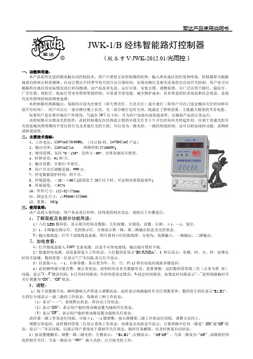
军达产品使用说明书一、功能和用途:本产品采用先进的微电脑自动控制技术,用户只要校正好控制器的时钟,输入所在地区的经度和纬度,控制器即可根据地球自转和公转的规律,自动计算出不同季节每天的日出日落时间,实现对路灯及相关设备的全自动开关控制。
用户也可以根据所在地区的实际情况进行时间微调。
该产品技术先进、运行可靠、安装方便,调整简便,可广泛应用于路灯、庭院灯、广告灯箱、霓虹灯、航标灯等室外照明智能控制。
可显著节省电能,减少维护成本,具有明显的经济效益和社会效益,是现代室外照明控制的理想选择。
本控制器有两路输出,每路均可设为全夜灯(即天黑亮灯、天亮关灯)或半夜灯(即用户可自己设定晚间关灯时间和早晨开灯时间)。
用户可以让一部分路灯晚上长亮,另一部分路灯定时关闭,既满足了照明需要,又能最大限度的节省电能。
如果用户是在寒冷地区户外使用,气温在20℃以下时,可为用户加装内部保温部件,以确保产品的正常运行。
该控制器可以增设光控组件,此时控制器仅在经纬度计算的早晨关灯至下午开灯时间内光控起作用,区别于普通光控开关的是晚间照明期间不受自控灯光及其他灯光的干扰,可以设为一路光控,一路经纬度控制,还可以附加雨控功能,采购时请特别说明。
二、主要技术指标:1、工作电压:220VAC/50/60Hz ;(可订制12、24VDC/AC 产品) 2、输出功率:220VAC/5A 两路控制2*1000W ;3、使用范围:东经70~136°,北纬5~60°,全国各地均可使用。
4、时钟误差:±1秒/天。
5、输出设置:全夜灯/半夜灯,6、用户开关灯调整范围:±99分。
7、停电数据保护时间:四个月。
8、环境温度:-20~+60℃(温度低于20℃以下时,可定制内部保温部件)9、环境湿度:<95% 10、外形尺寸:125×82×57mm 11、固定孔尺寸:△68mm×122mm 12、重量: 365g 三、使用说明:该产品投入使用前,用户务必进行时钟、经纬度的初次设定,请按以下步骤进行:1、了解面板及各部分功能用途:1)八位LED 数码管,显示相关时间及数据。
威尔恩灯光控制器说明书
For warranty information regarding this product, visit /warranty•Proper installation of this product requires the installer to have a good understanding of automotive electronics, systems and procedures.•Whelen Engineering requires the use of waterproof butt splices and/or connectors if that connector could be exposed to moisture.•Any holes, either created or utilized by this product, should be made both air- and watertight using a sealant recommended by your vehicle manufacturer.•Failure to use specified installation parts and/or hardware will void the product warranty.•If mounting this product requires drilling holes, the installer MUST be sure that no vehicle components or other vital parts could be damaged by the drilling process. Check both sides of the mounting surface before drilling begins. Also de-burr the holes and remove any metal shards or remnants. Install grommets into all wire passage holes.•If this manual states that this product may be mounted with suction cups, magnets, tape or Velcro®, clean the mounting surface with a 50/50 mix of isopropyl alcohol and water and dry thoroughly.•Do not install this product or route any wires in the deployment area of your air bag. Equipment mounted or located in the air bag deployment area will damage or reduce the effectiveness of the air bag, or become a projectile that could cause serious personal injury or death. Refer to your vehicle owner’s manual for the air bag deployment area. The User/Installer assumes full responsibility to determine proper mounting location, based on providing ultimate safety to all passengers inside the vehicle.•For this product to operate at optimum efficiency, a good electrical connection to chassis ground must be made. The recommendedprocedure requires the product ground wire to be connected directly to the NEGATIVE (-) battery post (this does not include products that use cigar power cords).•If this product uses a remote device for activation or control, make sure that this device is located in an area that allows both the vehicle and the device to be operated safely in any driving condition.•Do not attempt to activate or control this device in a hazardous driving situation.•This product contains either strobe light(s), halogen light(s), high-intensity LEDs or a combination of these lights. Do not stare directly into these lights. Momentary blindness and/or eye damage could result.•Use only soap and water to clean the outer lens. Use of other chemicals could result in premature lens cracking (crazing) and discoloration. Lenses in this condition have significantly reduced effectiveness and should be replaced immediately. Inspect and operate this product regularly to confirm its proper operation and mounting condition. Do not use a pressure washer to clean this product.•It is recommended that these instructions be stored in a safe place and referred to when performing maintenance and/or reinstallation of this product.•FAILURE TO FOLLOW THESE SAFETY PRECAUTIONS AND INSTRUCTIONS COULD RESULT IN DAMAGE TO THE PRODUCT OR VEHICLE AND/OR SERIOUS INJURY TO YOU AND YOUR PASSENGERS!A u t o m o t i v e : Warnings to InstallersWhelen’s emergency vehicle warning devices must be properly mounted and wired in order to be effective and safe. Read and follow all of Whelen’s written instructions when installing or using this device. Emergency vehicles are often operated under high speed stressful conditions which must be accounted for when installing all emergency warning devices. Controls should be placed within convenient reach of the operator so that they can operate the system without taking their eyes off the roadway. Emergency warning devices can require high electrical voltages and/or currents. Properly protect and use caution around live electrical connections.Grounding or shorting of electrical connections can cause high current arcing, which can cause personal injury and/or vehicle damage, including fire. Many electronic devices used in emergency vehicles can create or be affected by electromagnetic interference. Therefore, after installation of any electronic device it is necessary to test all electronic equipment simultaneously to insure that they operate free of interference from other components within the vehicle. Never power emergency warning equipment from the same circuit or share the same grounding circuit with radio communication equipment. All devices should be mounted in accordance with the manufacturer’s instructions and securely fastened to vehicle elements of sufficient strength to withstand the forces applied to the device. Driver and/or passenger air bags (SRS) will affect the way equipment should be mounted. This device should be mounted by permanent installation and within the zones specified by the vehicle manufacturer, if any. Any device mounted in the deployment area of an air bag will damage or reduce the effectiveness of the air bag and may damage or dislodge the device. Installer must be sure that this device, its mounting hardware and electrical supply wiring does not interfere with the air bag or the SRS wiring or sensors. Mounting the unit inside the vehicle by a method other than permanent installation is not recommended as unit may become dislodged during swerving; sudden braking or collision. Failure to follow instructions can result in personal injury. Whelen assumes no liability for any loss resulting from the use of this warning device. PROPER INSTALLATION COMBINED WITH OPERATOR TRAINING IN THE PROPER USE OF EMERGENCY WARNING DEVICES IS ESSENTIAL TO INSURE THE SAFETY OF EMERGENCY PERSONNEL AND THE PUBLIC.Warnings to UsersWhelen’s emergency vehicle warning devices are intended to alert other operators and pedestrians to the presence and operation of emergency vehicles and personnel. However, the use of this or any other Whelen emergency warning device does not guarantee that you will have the right-of-way or that other drivers and pedestrians will properly heed an emergency warning signal. Never assume you have the right-of-way. It is your responsibility to proceed safely before entering an intersection, driving against traffic, responding at a high rate of speed, or walking on or around traffic lanes. Emergency vehicle warning devices should be tested on a daily basis to ensure that they operate properly. When in actual use, the operator must ensure that both visual and audible warnings are not blocked by vehicle components (i.e.: open trunks or compartment doors), people, vehicles, or other obstructions. It is the user’s responsibility to understand and obey all laws regarding emergency warning devices. The user should be familiar with all applicable laws and regulations prior to the use of any emergency vehicle warning device. Whelen’s audible warning devices are designed to project sound in a forward direction away from the vehicle occupants. However, because sustained periodic exposure to loud sounds can cause hearing loss, all audible warning devices should be installed and operated in accordance with the standards established by the National Fire Protection Association.Safety FirstThis document provides all the necessary information to allow your Whelen product to be properly and safely installed. Before beginning the installation and/or operation of your new product, the installation technician and operator must read this manual completely. Important information is contained herein that could prevent serious injury or damage.WARNING: This product can expose you to chemicals including Methylene Chloride which is known to the State of California to cause cancer, and Bisphenol A, which is known to the State of California to cause birth defects or other reproductive harm. For more information go to .©1997 Whelen Engineering Company Inc.Form No.13240C (072607)Installation Guide:BL8140 Relay Box51 Winthrop RoadChester, Connecticut 06412-0684Phone: (860) 526-9504Internet: Salese-mail:*******************CustomerServicee-mail:*******************®ENGINEERING COMPANY INC.Selecting a mounting location...The logical choice for a mounting area would be a trunk or similar compartment. However, due to the wide variety of vehicles onto which the BL8140 could be installed, this is not always possible. The following guidelines will help the installer select an acceptable alternative:A)The BL8140 should be mounted on a metal surface to aidheat dissipation. Be sure that this surface is not one that either generates or is exposed to excessive heat during normal operation of the vehicle.B)Do not select a location where the BL8140 will be exposedto potential damage from any unsecured or loose equipment in the vehicle.C)Be sure the area selected will not allow the BL8140 to beexposed to water!D)When routing the BL8140’s wires, it is important to choosea path that will keep these wires away from excessive heatand from any vehicle equipment that could compromise the integrity of the wires (ex. trunk lids, door jams, etc.). WARNING!All customer supplied wires, that connect to the positive (+) terminal of the battery,must be sized to supply at least 125% ofthe maximum operating current, andfused “at the battery” to carry the load! Note:When extending the communication wires (BLUE & GREY), similar “twistedpair” wires MUST be used!When the best mounting location has been determined, securely fasten the BL8140 to its mounting surface using the supplied hardware.Caution:As it will be necessary to drill holes into the mounting surface, the installer MUST be surethat no vehicle components or other vitalparts could be damaged by the drillingprocess. Check both sides of the mountingsurface before drilling!BL8140 Dip Switches...All BL8140’s are shipped with a default dip switch configuration. These switches determine several aspects of the BL8140, including how the unit is addressed within the network. This section will offer a brief explanation of dip switch functionality. For a more detailed explanation of these switches, please refer to the “Advanced Settings” section found in the second half of this manual.The default dip switch configuration for the BL8140 is as follows:Dip Switch#Default Position1DOWN2DOWN3DOWN4UP5DOWN6UP7UP8UPSettings for use with MPC01 ver 2.xSettings for use with MPC01 ver 1.xDip Switch 1- This switch’s position should not be changed.Doing so effectively disables the ability of theBL8140 to properly operate.Dip Switch 2&3-These two switches work in conjunction witheach other. Their positions determine howthe output control channels are interpreted bythe network. Please refer to the “AdvancedSettings” section for a full explanation.Dip Switch 4-This switch controls the operation of push-button switch #9 on the Multi-PurposeController. Please refer to the AdvancedSettings section for a more detailedexplanation.Dip Switch 5&6-These two switches work in conjunction witheach other. Their positions determine thenetwork address of the BL8140s outputcontrol channel 1. The default address is 3. Dip Switch 7&8-These two switches work in conjunction witheach other. Their positions determine thenetwork address of the BL8140s outputcontrol channel 2. The default address is 4.Wiring the BL8140...The following diagram will illustrate the necessary wiring connections needed for BL8140 operation.BL8140 Channels...The BL8140 offers a total of 8 outputs located at the front of the unit (see Fig. 1). The outputs are identified in the illustration by numbers 1 through 8, counting from left to right. These outputs are grouped into “channels”. Each channel is recognized by the network as either a BL405 or a BL420A, depending upon the dip switch configuration.Channel 1 is comprised of outputs 1 - 4. Outputs 1-A, 1-B and 1-C are not individually controlled and function as a single, high-current output rated for up to 40 amps. Output’s 2, 3 and 4 are individually controlled and are rated for up to 20 Amps each.Channel 2 is comprised of outputs 5 - 8, each being individually controlled. Output 5 - 8 are rated for up to 10 Amps.When the dip switches are configured for ver 1.x of the configuration software, channel 1 and channel 2 emulate the BL405 halogen flasher. As such, the network believes that there are actually two BL405 flashers installed; channel 1 and channel 2. The following will illustrate how the outputs of the BL8140 are controlled by the Multi-Purpose Controller.Channel 1 (emulating a BL405 at address 1)BL8140 output #acts as BL405 output #1A, 1B & 1C1223344Channel 2 (emulating a BL405 at address 2)BL8140 output #acts asBL405 output #51627384When the BL8140 has been installed, it will be operated as configured by the Multi-Purpose Controller configuration software.Please refer to the configuration software manual for software configuration information.Advanced Settings...This section will provide advanced technicians with dip switch information that will allow the BL8140 to be configured in different ways for different needs. Please note that only experienced serial communications technicians should alter the default dip switch configuration. It is a good idea to record any changes made to the current dip switch configuration.Dip Switch 1-This switch is not used and should remain inthe default (DOWN) position.Dip Switch 2 & 3-These switches determine the emulation modeof the BL8140.DS#2DS#3UP UP In this position, the BL8140 tells the networkthat there are two BL405 4-outlet flashers onthe network. Channel 1 is seen as a BL405 andchannel 2 is seen as a BL405. Refer to the“BL8140 Channels...” section of this guide forinformation on output control and assignment. DOWN UP In this position, the BL8140 tells the networkthat channel 1 is a BL420 and that channel 2 isa BL405.UP DOWN In this position, the BL8140 tells the networkthat channel 1 is a BL405 and that channel 2 isa BL420.DOWN DOWN In this position, the BL8140 tells the networkthat channel 1 is a BL420 and that channel 2 isa BL420. DOWN/DOWN is the defaultposition for these switches.Dip Switch 4-This switch determines if or how the BL8140’s#8 output (channel 2/output 4) is controlled.UP In this position the BL8140 allows output #8 tobe controlled in a manner determined by theconfiguration software. UP is the defaultposition for this switch.DOWN In this position, output 8 control is assigned topush-button switch 9 on the MPC01 controlhead. This momentary switch, when pressed,“latches” output 8 on. Pressing this switch again“latches” output 8 off.Dip Switch 5 & 6-These switches determine the network addressof BL8140 channel 1.DS#5DS#6DOWN DOWN In this position, the address of channel 1 is 1. UP DOWN In this position, the address of channel 1 is 2. DOWN UP In this position, the address of channel 1 is 3.DOWN/UP is the default position for theseswitches.UP UP In this position, the address of channel 1 is 4. Dip Switch 7 & 8-These switches determine the network addressof BL8140 channel 2.DS#7DS#8DOWN DOWN In this position, the address of channel 2 is 1. UP DOWN In this position, the address of channel 2 is 2. DOWN UP In this position, the address of channel 2 is 3. UP UP In this position, the address of channel 2 is 4.UP/UP is the default position for theseswitches.I mportant Addressing Note! Channels 1 and 2 can NEVER share a common address UNLESS the two channels are emulating different products!Note:Although the BL8140 can emulate both the BL405 and the BL420, it does not emulate all oftheir characteristics. Major differences include:•The outputs of a channel emulating a BL405 or a BL420 do not share the same amperage limitations as do theoutputs of the models being emulated. See the wiringdiagram for output limitations.•The BL8140 can not “flash” an output. Regardless of the flash setting within the MPC01 configuration software,the BL8140 outputs are either on or off.。