(D2876)BR_Power_Diesel_EN
潍柴G-Drive发动机系列产品目录

North America3100 Golf Road, Rolling Meadows, IL, 60008 USAPhone 1-847-7257030Fax 1-847-7257060SingaporeWestech Building, 237 Pandan Loop #05-11,128424 SingaporePhone 65-67792729Fax 65-67797195Middle EastRA08, LA04, Jebel Ali Free Zone, Dubai, UAEPhone 97-1-48810650Fax 97-1-48810651Worldwide OfficesRussia178 Partizanskiy Avenue, office 606, Minsk,220075 Republic of BelarusPhone 375-17-3462290Fax 375-17-3462097IndiaNo-201, Pentagon Tower P3, Magarpattacity,Pune, Maharashtra, 411013 IndiaPhone 91-20-30162800Fax 91-20-30262820HeadquartersNO.197A, Fushou East Str., High-techIndustrial Development Zone,Weifang, Shandong, 261205 ChinaPhone 86-536-8269988Fax 86-536-8232079*****************For more information, please visit:THE BEST DIESELENGINE BY WEICHAIWeifang, China, R&DChicago, USA, R&DHangzhou, China,Computing CenterForli, Italy, R&DXi’an, China, R&DChongqing,China, R&DMarseilles, France, R&DWiesbaden, Germany, R&DYangzhou, China, R&DShanghai, China, R&D SYSTEM AND FIELD CERTIFICATIONSWeichai has four business platforms covering vehicle,powertrain, luxury yacht and auto parts. Its subsidiariesare spread across Europe, North America, SoutheastAsia and other regions. Global Research andDevelopment Operation centers are established inChicago, Marseilles, Forli, Frankfurt and Singapore. Atpresent, Weichai has offices in more than 30 countriesand over 400 authorized service stations. Weichaiproducts are sold in 100 countries and regions aroundthe world. The inventory of overseas engines reaches250,000 and that of heavy-duty trucks exceeds 100,000.Weichai is committed to extending its industry supplychain and improving its competitiveness throughstrategic investments. Weichai acquired FrenchBaudouin in 2009, further expanding engine business. In2012, Weichai Group acquired 75 percent of Italy'sFerretti, the world's largest luxury yacht manufacturingenterprise. Later in 2012, Weichai Group subsidiary,Weichai Power, signed a strategic cooperationagreement with KION Group, one of the world's topindustrial forklift truck manufacturers and global leaderof the hydraulic technology. Weichai aims to providemaximum satisfaction through its full range of engineand power offerings.R&D CAPABILITYIn China, Weichai Power is not only one of the earliestengine manufactures, but also the biggest diesel enginemanufacturer.Their product of industrial generation havebeen sold to 76 countries and regions, and receiveddeep trust from customers.For half a century, Weichai Power Weichai Power hasdedicated dedicated to explore the application anddevelopment of diesel engine, to provide full series, fullfield engine for customers, to active showing concern onecological environment, to constant R & D for bringingout low emission product,to be the No.1 of this industryand to obtain more acceptance from customers.Currently, Weichai Power has four series of engineproducts for land generation, including WP2.1-WP4.3series, WP4/WP6 series, WP10/WP12/WP13 series,Baudouin M26 series. At present, its high speed seriesproducts have been passed EU Stage II emissioncertificate. The power of Weichai diesel engine productsranges from 17.5 to 920kW and that of gas engineproducts ranges from 30 to 225kW, all of which havebeen sold in large quantities.Weichai Power, the supplier to provide you with overallpower service!M26WP10/12/13WP4/6WP2.1-4.3Gas EngineEU StageⅡEU StageⅢ$India CPCBⅠIndia CPCBⅡMechanical Injection PumpMechanical Injection PumpMechanical Injection PumpMechanical Injection PumpHigh-Pressure Common RailHigh-Pressure Common RailEGR+Mechanical Pump17.5601824405014440292090660Power (kW)WEICHAI G-DRIVE ENGINE TECHNOLOGYAfter optimization on the structure and sealing, the newlydesigned air filter has higher filtering efficiency, cleanerintake, more compact structure, and easier replacement offilter element;The optimization on intake and exhaust system, fuelsystem and turbocharger makes more fluent intake andcomplete combustion with a lower fuel consumption andusing cost; Optimization of cooling piping. Suspensionbracket can play the role of both vibration reduction andtransport bracket which is convenient for installation;The newly designed oil pan is of boat shape structure,which can increase the oil heat radiation area and play therole of vibration reduction;PRODUCT FEATURESGreat Fuel Efficiency● Optimized engine intake and fuel system; ● Lower engine fuel consumptionG-DRIVE DIESEL ENGINEEngineTypeCylinder numberBore×Stroke(mm)Fuel Consumption(g/kw·h)Electric SystemGovernor MethodWP2.1in line,four-stroke,Water-cooled485×92İ235DC12VMechanicWP4.3WP4WP6WP10WP12WP13M26in line, four-stoke,water-cooledin line,four-stroke,Water-cooledin line,four-stroke,Water-cooledin line,four-stroke,Water-cooledin line,four-stroke,Water-cooledin line,four-stroke,Water-cooledV-arrangement,four-stroke,Water-cooled4466666,8,12105x125105×130105×130126×130126×155127×165150×150İ235İ205İ205İ200İ200İ200İ200DC12V DC24V DC24V DC24V DC24V DC24V DC24VMechanic Mechanic/Electronic Mechanic/Electronic Mechanic/Electronic Mechanic/Electronic Mechanic/Electronic Electronic226B-3in line,four-stroke,Water-cooled3105×120İ205DC24VMechanic/ElectronicEngineTypeCylinder numberBore×Stroke(mm)Fuel Consumption(g/kw·h)Electric SystemGovernor MethodWP2.1in line,four-stroke,Water-cooled485×92İ235DC12VMechanicWP4.3WP4WP6WP10WP12WP13M26in line, four-stoke,water-cooledin line,four-stroke,Water-cooledin line,four-stroke,Water-cooledin line,four-stroke,Water-cooledin line,four-stroke,Water-cooledin line,four-stroke,Water-cooledV-arrangement,four-stroke,Water-cooled4466666,8,12105x125105×130105×130126×130126×155127×165150×150İ235İ205İ205İ200İ200İ200İ200DC12V DC24V DC24V DC24V DC24V DC24V DC24VMechanic Mechanic/Electronic Mechanic/Electronic Mechanic/Electronic Mechanic/Electronic Mechanic/Electronic Electronic226B-3in line,four-stroke,Water-cooled3105×120İ205DC24VMechanic/ElectronicPrime kW17.52233.33850212640453045609012013836506090108120144182216240288350182216240288350440880460920Standby kW19243742552329 44503350661001321524055661001181321582002382643173852002382643173854849685061012Displacement L2.12.53.94.34.12.12.53.94.33.13.14.54.56.86.83.13.14.54.54.56.86.89.79.79.711.612.59.79.79.711.612.515.931.815.931.8AspirationNANANANANANANANANANATTTATATANATTTATATATATATATATATATATATATATATATATATAGenset Power kW/KVA12/1516/2424/3030/3840/5016/2420/2530/3840/5024/3030/3850/6375/94100/125120/15030/3840/5050/6375/9490/113100/125120/150150/188180/225200/250250/313300/375150/188180/225200/250250/313300/375400/500800/1000400/500800/1000Type50Hz 1500rpm60Hz 1800rpm50Hz 1500rpm60Hz 1800rpm50Hz 1500rpm60Hz 1800rpm50Hz 1500rpm60Hz 1800rpmModelsWP2.1-WP4.3WP4/WP6WP10WP12/WP13M26Engine ModelWP2.1D18E2WP2.5D22E2WP3.9D33E2WP4.3D38E2WP4.1D50E2WP2.1D21E2WP2.5D26E2WP3.9D40E2WP4.3D45E2D226B-3DTD226B-3DWP4D66E200WP4D100E200WP6D132E200WP6D152E200D226B-3D1TD226B-3D1WP4D66E201WP4D100E201WP4D118E201WP6D132E201WP6D158E201WP10D200E200WP10D238E200WP10D264E200WP12D317E200WP13D385E200WP10D200E201WP10D238E201WP10D264E201WP12D317E201WP13D385E2016M26D484E20012M26D968E2006M26D506E20112M26D1012E201Land-BasedG-Drive EngineG-Drive Diesel Engine NA: Nature aspiration; T: Turbocharged ; TA : Turbocharged and aftercooled ;Engine ModelWP2.1CD18E1WP2.5CD22E1WP3.9CD33E1WP4.3CD38E1D226B-3CD TD226B-3CDWP4CD66E200WP4CD100E200WP6CD132E200WP6CD152E200D226B-3CD1TD226B-3CD1WP4CD66E201WP4CD100E201WP4CD118E201WP6CD132E201WP6CD158E201WP10CD200E200WP10CD238E200WP10CD264E200WP12CD317E200WP13CD385E200WP10CD200E201WP10CD238E201WP10CD264E201WP12CD317E201WP13CD385E2016M26CD506E20012M26CD1012E2006M26CD506E20112M26CD1012E201Prime kW17.52233.3383040609012013836506090108120144182216240288350182216240288350460920460920Standby kW1924374233446610013215240556610011813215820023826431738520023826431738550610125061012Displacement L2.12.53.94.33.13.14.54.56.86.83.13.14.54.54.56.86.89.79.79.711.612.59.79.79.711.612.515.931.815.931.8AspirationNA NA NA NA NA T T TA TA TA NA T T TA TA TA TA TA TA TA TA TA TA TA TA TA TA TA TA TA TAGenset power kW/KVA12/1516/2424/3030/3824/3030/3850/6375/94100/125120/15030/3840/5050/6375/9490/113100/125120/150150/188180/225200/250250/313300/375150/188180/225200/250250/313300/375400/500800/1000400/500800/1000Type50Hz 1500rpm60Hz 1800rpm50Hz 1500rpm 60Hz 1800rpm50Hz 1500rpm50Hz 1500rpm60Hz 1800rpmMarine-Based G-Drive EngineModelsWP2.1-WP4.3WP10/WP12/WP13M26WP4/WP6G-Drive Diesel EngineNA: Nature aspiration; T: Turbocharged ; TA : Turbocharged and aftercooled ;Prime kWElectric SystemGovernor MethodGenset Power kW/KVACylinder NumberEngine ModelBore×StrokemmFuel Consumption g/kw.hDisplacementLAspirationOverviewG-DRIVE GAS ENGINEEach series of Weichai generating gas engine is developed and designed on the basis of corresponding matured Weichai diesel engine and uses LNG, CNG, and methane as the fuel. A completely new design on piston, valve and valve seat ring and cooling method is conducted on it as per such advantages of gas engine as high heat value and high exhaust temperature and so on. With mature and reliable WoodWard gas electrical control injection system, its power, reliability and economy can reach the same level of similar diesel engine, which makes it the ideal power for gen-set with gas engine.More than 10000 gas engines have been sold every year.* Available After December 201490108120144182216240260288660550350Electronic Electronic Electronic Electronic Electronic Electronic Electronic Electronic Electronic ElectronicElectronic Electronic 215215215215215215215215215215215215DC24V DC24V DC24V DC24V DC24V DC24V DC24V DC24V DC24V DC24VDC24V DC24V 75/9490/113100/125120/150150/188180/225200/250230/287.5250/312.5600/705500/625500/625666666666121212WP6D100E200NG WP6D118E200NG WP6D132E200NG WP10D158E200NG WP10D200E200NG WP12D238E200NG WP12D260E200NG WP13D286E200NG WP13D317E200NG *12M26D726Z200NG*12M26D605E200NG *6M26D385Z200NG 150×150105×130105×130105×130126×130126×130126×155126×155127×165127×165150×150150×150 6.26.26.29.79.711.611.612.512.531.831.815.9T T T T T T T T T TT T T: TurbochargedWeichai Power has a broad market in 100 countries and regions in five continents. Recently, it has had aninternational service network covering the global operations with 30 overseas institutions and 247service agencies,which proves that Weichai Power has the initial ability to provide services to worldwide uses.INTERNATIONAL SERVICE NETWORKNorth America Operations Center (Chicago)European R&D and ManufacturingBase (Marseille)Singapore Operations CenterXu WenwuRussiaMongoliaKazakstanTajikistanAzerbaijianSingaporeIndonesiaPhilippinesMalaysiaThailandBurmaVietnamIndiaBangladeshPakistanIranUnited Arab EmiratesSaudi ArabiaFranceTurkeyAlgeriaLibyaKenyaEthiopiaSudanSouth AfricaAngolaNigeriaGhanaBrazilEcuadorChilePeruAmericaAn PengfeiSun GongchunZhang MengZhao XiaoguangShan HongwuCheng ShouliangLi HaoZhang TengfeiXu HongluanHu XudongSun ShaojieNing AizhongPan ShankaoZhang YongLiu HaitaoLuan ShengzhiChen YunSui ZhenHuo ChunleiZhang LeiHuo ChunleiLiu HuiCao LeiHu XiaoqunMa XiaoxiaoGuan FengFu YongshengSong ZhipingZhang HaishengChen WeichaoWang HaiqiangLin ChuanmeiZhang YunjianLiu Haifeng00792991132800097699602398007701172546600992929630037009945598055580065923692590062812951969810063923350368200601112291558006691117828800959450043892008494432699600917387089802008801711542654009221352493100098912434198800971196852202009665633570180086189****808500905393456501002136966642540021892382829700254717498889002519249094630024996812678000277172820450024492477127500234816888880800233246588890005511259467250056956034024005198413178800122425065640016302102355Yang ZhaoxiaDing WeiWang HongshanYang ZhaoxiaZhuo LaixianLiu SenHuang HongguangLi JianChen WushengAreaCommonwealth ofIndenpent StatesSoutheast AsiaSouth AsiaMiddle EastEurope andNorth AfricaEast AfricaSouth AfricaWest AfricaSouth AmericaNorth AmericaLiu HaifengBill ShenOfficeHao FengZhong LeiAmit DeshpandeGao JinguiWan KuishaoWang ChangcongWang LuSales Manager Service Manager**************************************************************************************************************************************************************************************************************************************************************************************************************************************************************************************************Local Tel E-mail。
8726C 8726W Addressable Remote Lamps 说明书

INTRODUCTIONThe 8726C (round plate) and 8726W (rectangular plate) Address-able Remote Lamps, shown in Figure 1, operate as an additional LED indicator for a device in the fire alarm control system’s addres-sable device circuit. The 8726C/8726W can be used when a device already has an accessory. The 8726C/8726W can be installed at any location of an addressable device circuit, and it remotely indicates the status of the device(s) in that same circuit.Mode of OperationThe 8726C/8726W has one mode of operation: Direct Addressing Mode. The two-position jumper P1 must be positioned to set the mode to Direct Addressing.When set and programmed to Direct Addressing Mode, system logic and programming determine when the ILED-H will blink.Controls and IndicatorsIn Direct Addressing mode, the LED on the 8726C/8726W is controlled by logic functions programmed using the CIS-4 Tool. In Direct Addressing mode, the 8726C/8726W blink color (red only) cannot be changed.PROGRAMMINGRefer to Figure 2 for the location of the programming holes and jumper P1.Direct Addressing ModeTo set the 8726C/8726W to Direct Addressing Mode follow the steps listed below:1.Determine a unique address for the 8726C/8726W.2.Set jumper P1 to position 2 and3.3.Connect the 8726C/8726W to the 8720 Programmer/Tester byinserting the plug from the cable provided with the 8720 Programmer/Tester into the programming holes on the 8726C/8726W board.4.Follow the instructions in the 8720 Programmer/Tester Manual, P/N 315-033260FA, to program the 8726C/8726W to the desired address. Record the device address on the label located on the 8726C/8726W front panel.INSTALLATION INSTRUCTIONS AND WIRING FORINTELLIGENT REMOTE LAMPSP/N 8726C AND 8726WFigure 18726C And 8726W Remote LampsSiemens Industry, Inc.Building Technologies Division • Florham Park, NJ Tel: (973) 593-2600 • Fax: (973) 593-6670Web: Figure 28726 Printed Circuit Board5.In the CIS-4 Programming Tool, assign the 8726C/8726W to an output zone. When an Input Group that is assigned to that Output Zone reports an off-normal event, the 8726C/8726W will blink red if the reported event type matches the output type selected for its zone. Refer to the CIS-4 Manual for further information.6.The 8726C/8726W can now be installed and wired to the system.WIRINGWARNING: Disconnect BATTERY and AC prior to working on equipment.Refer to the wiring diagram in Figure 3 below to wire the 8726C/8726W.NOTE: The 8726C/8726W is polarity insensitive. Switching Line1 and Line2 has no effect on performance.Recommended wire size:18 AWG minimum, 14 AWG maximumWire larger than 14 AWG can damage the connector.LINE2LINE1TO ADDRESSABLE DEVICE CIRCUITFigure 3Wiring The 8726C/8726WINSTALLATIONNOTE: Be sure to program the 8726C/8726W before installing the unit.The 8726C/8726W may be placed at any location on the address-able device circuit. Use a single-gang switch box (user supplied) for mounting the 8726W. Use a 4-inch octagonal conduit box (user supplied) for mounting the 8726C. Refer to Figure 4 for typical 8726C/8726W installation.The number of 8726C/8726W modules on the addressable device circuit must be included in the total count of intelligent field devices.For the restriction of the total number of devices in the FDLC loop,refer to the FDLC Installation Instructions, P/N 315-447360FA.ELECTRICAL RATINGSDO NOT USE REAR CONDUIT ENTRYFigure 4Mounting The 8726Wtn e r r u C t u p n I Am 1。
迈克尔顿工业有限公司 Stealth XC

Filter Size
6 x 14 (152 x 356)
3
6, 8, 10, 12
26 47 18 41 7
(125, 203, 254, 305) (660) (1194) (457) (1041) (178)
6 x 18 (152 x 457)
9 1/8 x 10 1/2 6 x 18 (232 x 267) (152 x 457)
W W2 H
1
4, 5, 6, 8
20 41 14
(102, 127, 152, 203) (508) (1041) (356)
L
36 (914)
Induced Air
B
Inlet
IW x IH
6
6 x 14
(152) (152 x 356)
Outlet Discharge DW x DH
8 1/8 x 4 1/4 (206 x 108)
q Hot Water Coil Section Model 35SWXC STEALTH XC
Standard Features:
• Coil section installed on unit discharge. • Coil (and header on multi-circuit units) is installed in
ENGINEER:
DATE
B SERIES SUPERSEDES DRAWING NO.
CONTRACTOR:
11 - 4 - 22 3500 10 - 28 - 22 35SXC-1
Nailor Industries Inc. reserves the right to change any information concerning product or pricing without notice.
英国科森Comtherm ECO拉幅定型机专用燃烧器
A2 20
A2
22
西门子烧嘴控制器
A2 24
LFL 1.335
A2 11
1) 在燃烧器的所有接线应符合惯例的当地电气规范的要求。 2) 使用西门子LFL 1335控制器,在点火启动时,燃烧器会自动执行吹扫程序,避免炉膛发生 爆燃事故。 3) 使用西门子SQN71.603R19执行器,接收三点信号控制。 4) 客户应严格按照图示进行接线,非专业人员请勿操作。 5) 严禁将燃气管路作为地线使用。
工业 燃烧器
拉幅机燃烧器-ECO
目录
概述............................................................................................................................................................2 一、技术说明............................................................................................................................................3 1.1技术参数..............................................................................................................................................3 1.2 ECO配置............................................................................................................................................4 1.3 电路图及接线说明............................................................................................................................5 1.4 ECO安装尺寸....................................................................................................................................5 二、安装及调试说明................................................................................................................................6 2.1 安装....................................................................................................................................................6 2.2调试及启动说明.................................................................................................................................7 2.3 故障解决............................................................................................................................................9
Jtag 接口介绍

JTAG Interface :Common Pinoutsamt_ann003 (v1.1) Application NoteOVERVIEWThis Application Note resumes the Common JTAG interfacepinouts used by the most popular manufacturers ofprocessors, FPGAs or CPLDs devices as ARM, Altera,Lattice, MIPS, Xilinx and so more …General Notes:• Amontec accepts NO responsibility for the accuracy of thefollowing information. These are the pinouts that our JTAGadapters use, but a semiconductor manufacturer maychange these specifications at any time. We stronglyrecommend that you use the BDM/ISP/JTAG headerspecified by the semiconductor manufacturer and refer tothis list before connecting to your target.• VREF pins should be the I/O voltage reference. This signalis used to determine the electrical characteristics of theother IO signals. VREF should be regulated• If you are building your own board, place the header asclose to the processor as possible, use short traces ofapproximately equal length on all clock and data signals.• Unless otherwise indicated, all headers are male dual-rowheader connectors (2.54 mm pitch).Pins are identified by number and type:• o = output from target processor to the emulator.• I = input to target processor from the emulator.• p = power pin• od = open drain driven from the JTAG emulator, eitherfloating or actively held low• nc = not connected, ie: not driven nor read by ODDinterface• k = key, pin is typically missing from the target boardPowered byALL BDM / ISP / JTAG interfacesdescribed in this dodument may beemulated by Amontec ChameleonPOD!BDM \ ISP \ JTAG CONNECTORSOverview (1)BDM \ ISP \ JTAG ConnectorS (1)ALTERA ByteBlaster MV and II 10-pin (JTAG) (2)ALTERA ByteBlaster MV and II 10-pin (PS MODE) (2)ALTERA ByteBlaster II 10-pin (AS MODE) (3)AMD – Athlon 16-pin (JTAG) (3)AMD – Èlan SC520 12-pin (JTAG) (4)AMD – Opteron 26-pin (JTAG) (4)ARM 14-pin (JTAG) (5)ARM 20-pin (JTAG) (5)ARM 20-pin with RTCK feature (JTAG) (6)ATMEL AVR STKx00 ISP Download Cable 10-pin (ISP) (6)ATMEL ATDH2081 Download Cable 10-pin (ISP) (7)CYPRESS UltraISR Download cable 10-pin (JTAG) (7)CYPRESS UltraISR Download cable 10-pin (ISR) (8)IBM / MOTOROLA PPC “COP” Interface 16-pin (JTAG) (8)IBM 4xx 16-pin (JTAG RISCWatch) (9)LATTICE ispDOWNLOAD 8-pin (JTAG and ISP) (9)LATTICE ispDOWNLOAD 10-pin (JTAG and ISP) (10)MIPS – EJTAG-2.5 14-pin (JTAG) (10)MOTOROLA Freescale Colfire 26-pin (BDM P&E) (11)MOTOROLA Freescale MPCxxx 10-pin (BDM) (11)MOTOROLA “OnCe”, On Chip Emulation 14-pin (JTAG) (12)PHILLIPS's MIPS 20-pin (JTAG) (12)ST PSD FlashLINK programmer 14-pin (JTAG) (13)TI MSP430 14-pin (JTAG) (13)TOSHIBA's MIPS 20-pin (JTAG) (14)XILINX Parallel Cable III 9-pin (Slave Serial) (14)XILINX Parallel Cable III and IV 9-pin (JTAG) (15)XILINX Parallel IV 14-pin (JTAG and Slave Serial) (15)Figure and Table index (16)Content Revisions (17)Contact Amontec (17)© 2000-2006 Amontec, Inc. All rights reserved. All Amontec registered trademarks, patents, and disclaimers are as listed at /legal.shtml All other trademarks and registered trademarks are the property of their respective owners. All specifications are subject to change without notice.Amontec JTAG Interface: Common PinoutsALTERA BYTEBLASTER MV AND II 10-PIN (JTAG)AMONTEC REF: ALTERA10JTAGNAME: ALTERA ByteBlaster MV and II (JTAG)CATEGORY: JTAGTARGET: All ALTERA CPLDs and FPGAsCOMMENT: See ALTERA ByteBlaster MV or II datasheet for more detailsCONNECTOR: 10-pin Header (2.54mm)CONNECTOR TYPE: d ualTCK i 1 2 p GNDTDO o 3 4 p VREFTMS i 5 6 nc -- nc 7 8 nc -TDI i 9 10 p gndTable 1: ALTERA ByteBlaster MV and II (JTAG) connector (target board)ALTERA BYTEBLASTER MV AND II 10-PIN (PS MODE)AMONTEC REF: ALTERA10PSNAME: ALTERA ByteBlaster MV and II (PS MODE)CATEGORY: ISPTARGET: A large part of ALTERA CPLDs and FPGAsCOMMENT: See ALTERA ByteBlaster MV or II datasheet for more detailsCONNECTOR: 10-pin Header (2.54mm)CONNECTOR TYPE: d ualDCLK i 1 2 p GNDCONF_DONE o 3 4 p VREFnCONFIG i 5 6 nc -nSTATUS o 7 8 nc -DATA0 i 9 10 p gndTable 2: ALTERA ByteBlaster MV and II (PS MODE) connector (target board)© 2000-2006 Amontec, Inc. All rights reserved. All Amontec registered trademarks, patents, and disclaimers are as listed at /legal.shtml All other trademarks and registered trademarks are the property of their respective owners. All specifications are subject to change without notice.JTAG Interface: Common Pinouts AmontecALTERA BYTEBLASTER II 10-PIN (AS MODE)AMONTEC REF: ALTERA10ASNAME: ALTERA ByteBlaster MV and II (AS MODE)CATEGORY: ISPTARGET: A large part of ALTERA FPGAsCOMMENT: See ALTERA ByteBlaster II datasheet for more detailsCONNECTOR: 10-pin Header (2.54mm)CONNECTOR TYPE: d ualDCLK i 1 2 p GNDCONF_DONE o 3 4 p VREFnCONFIG i 5 6 i nCONFIGnSTATUS o 7 8 i nCSDATA0 i 9 10 p gndTable 3: ALTERA ByteBlaster MV and II (AS MODE) connector (target board)AMD – ATHLON 16-PIN (JTAG)AMONTEC REF: AMD16ATHLONNAME: AMD - AthlonCATEGORY: JTAGTARGET: AMD - AthlonCOMMENT: See AMD's Athlon datasheet for more detailsCONNECTOR: 16-pin Header (1.27mm)CONNECTOR TYPE: d ualVREF p 1 2 i TCK- nc 3 4 i TMS- nc 5 6 nc -- nc 7 8 i TDI- nc 9 10 i TRST_NGND p 11 12 o TDODBREQ_N i 13 14 o DBRDYSRST_N od 15 16 i PLLTEST_NTable 4: AMD - Athlon connector (target board)© 2000-2006 Amontec, Inc. All rights reserved. All Amontec registered trademarks, patents, and disclaimers are as listed at /legal.shtml All other trademarks and registered trademarks are the property of their respective owners. All specifications are subject to change without notice.Amontec JTAG Interface: Common PinoutsAMD – ÈLAN SC520 12-PIN (JTAG)AMONTEC REF: AMD12ELANNAME: AMD – Èlan SC520CATEGORY: JTAGTARGET: AMD Èlan SC520COMMENT: See AMD's Èlan SC520 datasheet for more detailsCONNECTOR: 12-pin Header (2mm)CONNECTOR TYPE: d ualGND p 1 2 p VREFTCK i 3 4 o CMDACKTMS i 5 6 i BR/TCTDI i 7 8 o STOP/TXTDO o 9 10 o TRIG/TRACESSRST_N od 11 12 k KEYTable 5: AMD – Èlan SC520 connector (target board)AMD – OPTERON 26-PIN (JTAG)AMONTEC REF: AMD26OPTERONNAME: AMD - OpteronCATEGORY: JTAGTARGET: AMD - OpteronCOMMENT: See AMD's Opteron datasheet for more detailsCONNECTOR: 26-pin Header (1.27mm)CONNECTOR TYPE: d ualGND p 1 2 p GNDRSVD1 o 3 4 p GNDRSVD0 i 5 6 p GNDDBREQ_N i 7 8 p GNDDBRDY o 9 10 p GNDTCK i 11 12 p GNDTMS i 13 14 p GNDTDI i 15 16 p GNDTRST_N i 17 18 p GNDTDO o 19 20 p GNDVREF p 21 22 p GNDVREF p 23 24 nc -KEY k 25 26 nc –Table 6: AMD - Opteron connector (target board)© 2000-2006 Amontec, Inc. All rights reserved. All Amontec registered trademarks, patents, and disclaimers are as listed at /legal.shtml All other trademarks and registered trademarks are the property of their respective owners. All specifications are subject to change without notice.JTAG Interface: Common Pinouts AmontecARM 14-PIN (JTAG)AMONTEC REF: ARM14NAME: ARM 14-pinCATEGORY: JTAGTARGET: ARM7, ARM9, ARM10, XSCALECOMMENT: There are two standard ARM pinouts, an older 14 pin specification and a newer 20 pin specification. CONNECTOR: 14-pin Header (2.54mm)CONNECTOR TYPE: d ualVREF p 1 2 p GNDTRST_N i 3 4 p GNDTDI i 5 6 p GNDTMS i 7 8 p GNDTCK i 9 10 p GNDTDO o 11 12 od SRST_NVREF p 13 14 p GNDTable 7: ARM 14-pin connector (target board)ARM 20-PIN (JTAG)AMONTEC REF: ARM20NAME: ARM 20-pinCATEGORY: JTAGTARGET: ARM7, ARM9, ARM10, XSCALECOMMENT: There are two standard ARM pinouts, an older 14 pin specification and a newer 20 pin specification. CONNECTOR: 20-pin Header (2.54mm)CONNECTOR TYPE: d ualVREF p 1 2 nc -TRST_N i 3 4 p GNDTDI i 5 6 p GNDTMS i 7 8 p GNDTCK i 9 10 p GND- nc 11 12 p GNDTDO o 13 14 p GNDSRST_N od 15 16 p GND- nc 17 18 p GND- nc 19 20 p GNDTable 8: ARM 20-pin connector (target board)© 2000-2006 Amontec, Inc. All rights reserved. All Amontec registered trademarks, patents, and disclaimers are as listed at /legal.shtml All other trademarks and registered trademarks are the property of their respective owners. All specifications are subject to change without notice.Amontec JTAG Interface: Common PinoutsARM 20-PIN WITH RTCK FEATURE (JTAG)AMONTEC REF: ARM20RTCKNAME: ARM 20-pin with RTCK featureCATEGORY: JTAGTARGET: ARM7-s, ARM9-s, ARM10-s. ARMx-s processor series use the RTCK JTAG Baudrate feature. COMMENT:CONNECTOR: 20-pin Header (2.54mm)CONNECTOR TYPE: d ualVREF p 1 2 nc -TRST_N i 3 4 p GNDTDI i 5 6 p GNDTMS i 7 8 p GNDTCK i 9 10 p GNDRTCK o 11 12 p GNDTDO o 13 14 p GNDSRST_N od 15 16 p GND- nc 17 18 p GND- nc 19 20 p GNDTable 9: ARM 20-pin connector with RTCK feature (target board)ATMEL AVR STKX00 ISP DOWNLOAD CABLE 10-PIN (ISP)AMONTEC REF: STKx0010NAME: ATMEL AVR STKx00 ISP Download Cable (STK200 and STK300)CATEGORY: ISPTARGET: ATMEL AVR micro-processorCOMMENT: See ATMEL AVR STK200 or STK300 download cable datasheet for more details.CONNECTOR: 10-pin Header (2.54mm)CONNECTOR TYPE: d ualMOSI i 1 2 p VREFLED i 3 4 p GNDRST i 5 6 p GNDSCK i 7 8 p GNDMISO o 9 10 p GNDTable 10: ATMEL AVR STKx00 ISP Download Cable connector (target board)© 2000-2006 Amontec, Inc. All rights reserved. All Amontec registered trademarks, patents, and disclaimers are as listed at /legal.shtml All other trademarks and registered trademarks are the property of their respective owners. All specifications are subject to change without notice.JTAG Interface: Common Pinouts AmontecATMEL ATDH2081 DOWNLOAD CABLE 10-PIN (ISP)AMONTEC REF: ATDH208110NAME: ATMEL ATDH2081 Download CableCATEGORY: ISPTARGET: Atmel’s ATDH2081 download cable allows designers to configure Atmel’s family of AT6K/40K Field Programmable Gate Array (FPGA) and AT94K Field Programmable System Level Integrated Circuit(FPSLIC) devices. Download CableCOMMENT: See CYPRESS UltraISR JTAG download cable datasheet for more details.CONNECTOR: 10-pin Header (2.54mm)CONNECTOR TYPE: d ualDI i 1 2 i CONCI i 3 4 nc CODO nc 5 6 o ERRGND p 7 8 p VREF- nc 9 10 nc -Table 11: ATMEL ATDH2081 Download Cable connector (target board)CYPRESS ULTRAISR DOWNLOAD CABLE 10-PIN (JTAG)AMONTEC REF: ULTRAISR10NAME: CYPRESS UltraISR Download cable (JTAG)CATEGORY: JTAGTARGET: All Cypress CPLD TypesCOMMENT: See CYPRESS UltraISR JTAG download cable datasheet for more details.CONNECTOR: 10-pin Header (2.54mm)CONNECTOR TYPE: d ualGND p 1 2 i TMSJTAGen i 3 4 i TCKISR i 5 6 i TDIVREF p 7 8 kTDO o 9 10 p GNDGND p 1 2 i TMSTable 12: CYPRESS UltraISR Download cable (JTAG) connector (target board)© 2000-2006 Amontec, Inc. All rights reserved. All Amontec registered trademarks, patents, and disclaimers are as listed at /legal.shtml All other trademarks and registered trademarks are the property of their respective owners. All specifications are subject to change without notice.Amontec JTAG Interface: Common PinoutsCYPRESS ULTRAISR DOWNLOAD CABLE 10-PIN (ISR)AMONTEC REF: ULTRAISR10NAME: CYPRESS UltraISR Download cable (ISR)CATEGORY: ISPTARGET: All Cypress CPLD TypesCOMMENT: See CYPRESS UltraISR JTAG download cable datasheet for more details.CONNECTOR: 10-pin Header (2.54mm)CONNECTOR TYPE: d ualGND p 1 2 i SMODEISRVPP i 3 4 i SCLKISR i 5 6 i SDIVREF p 7 8 kSDO o 9 10 p GNDTable 13: CYPRESS UltraISR Download cable (ISR) connector (target board)IBM / MOTOROLA PPC “COP” INTERFACE 16-PIN (JTAG)AMONTEC REF: COP16NAME: COP InterfaceCATEGORY: JTAGTARGET: MOTOROLA Freescale PowerPC 6xx, 7xx, 8xxx and IBM PowerPC 6xx and 7xxCOMMENT: IBM also refers to this connection as RISCWatch.CONNECTOR: 16-pin Header (2.54mm)CONNECTOR TYPE: d ualTDO o 1 2 i QACK_NTDI i 3 4 i TRST_NHALTED o 5 6 p VREFTCK i 7 8 nc -TMS i 9 10 nc -SRST_N od 11 12 p GNDHRST_N od 13 14 nc -CKSTP_OUT o 15 16 p GNDTable 14: IBM / MOTOROLA “COP” Interface connector (target board)© 2000-2006 Amontec, Inc. All rights reserved. All Amontec registered trademarks, patents, and disclaimers are as listed at /legal.shtml All other trademarks and registered trademarks are the property of their respective owners. All specifications are subject to change without notice.JTAG Interface: Common Pinouts Amontec© 2000-2006 Amontec, Inc. All rights reserved. All Amontec registered trademarks, patents, and disclaimers are as listed at /legal.shtmlAll other trademarks and registered trademarks are the property of their respective owners. All specifications are subject to change without notice.IBM 4XX 16-PIN (JTAG RISCWATCH)AMONTEC REF: IBM16 NAME: IBM 4xx CATEGORY: JTAG TARGET: IBM 4xxCOMMENT: IBM also calls this RISCWatch. CONNECTOR:16-pin Header (2.54mm)CONNECTOR TYPE: d ualTDO o 1 2 nc - TDI i 3 4 i TRST_N HALTED o 5 6 p VREFTCK i 7 8 nc - TMS i 9 10 nc - HALT i 11 12 p GND SRST_N od 13 14 k KEY- nc 15 16 p GND Table 15 IBM 4xx connector (target board)LATTICE ISPDOWNLOAD 8-PIN (JTAG AND ISP)AMONTEC REF: LATTICE8NAME: LATTICE ispDOWNLOAD 8-pin connector CATEGORY: JTAG ISPTARGET: All LATTICE CPLDsCOMMENT: See LATTICE ispDOWNLOAD JTAG download cable datasheet for more details. CONNECTOR:8-pin Header (2.54mm)CONNECTOR TYPE: i nlineVREF p 1SDO_TDO o 2 SDI_TDI i 3 ISPEN_N i 4- nc 5 MODE_TMS i 6GND p 7 SCLK_TCK i 8Table 16: LATTICE ispDOWNLOAD 8-pin connector (target board)Amontec JTAG Interface: Common PinoutsLATTICE ISPDOWNLOAD 10-PIN (JTAG AND ISP)AMONTEC REF: LATTICE10NAME: LATTICE ispDOWNLOAD 10-pin headerCATEGORY: JTAG ISPTARGET: All LATTICE CPLDsCOMMENT: See LATTICE ispDOWNLOAD JTAG download cable datasheet for more details.CONNECTOR: 10-pin Header (2.54mm)CONNECTOR TYPE: d ualTCK i 1 2 nc -TMS i 3 4 p GNDTDI i 5 6 p VREFTDO o 7 8 p GNDTRST i 9 10 i ISPEN_NTable 17: LATTICE ispDOWNLOAD 10-pin connector (target board)MIPS – EJTAG-2.5 14-PIN (JTAG)AMONTEC REF: MIPS14NAME: MIPS - EJTAG 2.5CATEGORY: JTAGTARGET: MIPS, MIPS32, MIPS64, MIPS-32, MIPS-64,COMMENT: There are many MIPS JTAG headers in use. This is the one specified by MTI for EJTAG 2.5 CONNECTOR: 14-pin Header (2.54mm)CONNECTOR TYPE: d ualTRST_N i 1 2 p GNDTDI i 3 4 p GNDTDO o 5 6 p GNDTMS i 7 8 p GNDTCK i 9 10 p GNDSRST_N od 11 12 k KEYDINT i 13 14 p VREFTable 18: MIPS - EJTAG 2.5 connector (target board)© 2000-2006 Amontec, Inc. All rights reserved. All Amontec registered trademarks, patents, and disclaimers are as listed at /legal.shtml All other trademarks and registered trademarks are the property of their respective owners. All specifications are subject to change without notice.MOTOROLA FREESCALE COLFIRE 26-PIN (BDM P&E)AMONTEC REF: COLDFIRE26NAME: MOTOROLA Freescale Colfire BDM P&E (cable_cf)CATEGORY: BDMTARGET: MOTOROLA Freescale ColfireCOMMENT: See COLDFIRE P&E BDM debug product datasheet for more details.CONNECTOR: 26-pin Header (2.54mm)CONNECTOR TYPE: d ual- nc 1 2 i BKPT_NGND p 3 4 i DSCLKGND p 5 6 nc -SRST_N od 7 8 i DSIVREF p 9 10 o DSOGND p 11 12 o PST3PST2 o 13 14 o PST1PST0 o 15 16 nc (D3)(D2) nc 17 18 nc (D1)(D0) nc 19 20 p GND- nc 21 22 nc -GND p 23 24 o CPUCLKVREF p 25 26 i TEA_NTable 19: MOTOROLA Freescale Colfire (target board)MOTOROLA FREESCALE MPCXXX 10-PIN (BDM)AMONTEC REF: BDM10NAME: BDM for MOTOROLA FreescaleCATEGORY: BDMTARGET: MOTOROLA Freescale MPC8xx, MPC5xxCOMMENT: It is vital that pins 1 and 6 properly reflect the status of the target processor immediately following RESET. Some processors have configurable pins (MPC8xx, etc.) that are specified by a resetconfiguration word at the time of reset. These pins must be set properly and must ALWAYS reflect thestatus of the processor correctly. Check the ‘hardware reset configuration word’ in the MOTOROLAFreescale User’s manual.CONNECTOR: 10-pin Header (2.54mm)CONNECTOR TYPE: d ualFRZ_VFLS0 o 1 2 o SSRST_NGND p 3 4 i DSCKGND p 5 6 o FRZ_VFLS1SRST_N od 7 8 i DSDIVREF p 9 10 o DSDOTable 20: MOTOROLA Freescale MPCxxx BDM connector (target board)© 2000-2006 Amontec, Inc. All rights reserved. All Amontec registered trademarks, patents, and disclaimers are as listed at /legal.shtml All other trademarks and registered trademarks are the property of their respective owners. All specifications are subject to change without notice.MOTOROLA “ONCE”, ON CHIP EMULATION 14-PIN (JTAG)AMONTEC REF: ONCE14NAME: OnCe, On Chip EmulationCATEGORY: JTAGTARGET: MOTOROLA Freescale DSP, M*CORECOMMENT: -CONNECTOR: 14-pin Header (2.54mm)CONNECTOR TYPE: d ualTDI i 1 2 p GNDTDO o 3 4 p GNDTCK i 5 6 p GND- nc 7 8 nc -SRST_N od 9 10 i TMSVREF p 11 12 p GND- nc 13 14 i TRST_NTable 21: MOTOROLA “OnCe” connector (target board)PHILLIPS'S MIPS 20-PIN (JTAG)AMONTEC REF: MIPS20PHILLIPSNAME: PHILLIPS's MIPSCATEGORY: JTAGTARGET: MIPS, MIPS32, MIPS64, MIPS-32, MIPS-64COMMENT: See PHILLIPS's MIPS datasheet for more detailsCONNECTOR: 20-pin Header (2.54mm)CONNECTOR TYPE: d ualTRST_N i 1 2 p GNDTDI i 3 4 p GNDTDO o 5 6 p GNDTMS i 7 8 p GNDTCK i 9 10 p GNDSRST_N od 11 12 p GND- nc 13 14 p GND- nc 15 16 p GND- nc 17 18 p GND- nc 19 20 p GNDTable 22: PHILLIPS's MIPS connector (target board)© 2000-2006 Amontec, Inc. All rights reserved. All Amontec registered trademarks, patents, and disclaimers are as listed at /legal.shtml All other trademarks and registered trademarks are the property of their respective owners. All specifications are subject to change without notice.ST PSD FLASHLINK PROGRAMMER 14-PIN (JTAG)AMONTEC REF: PSD14NAME: ST PSD FlashLINK programmerCATEGORY: JTAGTARGET: All ST PSD Flash productsCOMMENT: See ST PSD FlashLINK JTAG cable datasheet for more details.CONNECTOR: 14-pin Header (2.54mm)CONNECTOR TYPE: d ualJEN_N od 1 2 od TRST_NGND p3 4 od i CNTLTDI i 5 6 o TSTATVREF p 7 8 i RST_NTMS i 9 10 p GNDTCK i 11 12 p GNDTDO o 13 14 o TERR_NTable 23: ST PSD FlashLINK programmer connector (target board)TI MSP430 14-PIN (JTAG)AMONTEC REF: MSP43014NAME: TI MSP430 JTAGCATEGORY: JTAGTARGET: Texas Instruments TI MSP430COMMENT: See Texas Instruments TI MSP430 JTAG interface for more details.CONNECTOR: 14-pin Header (2.54mm)CONNECTOR TYPE: d ualTDO o 1 2 p VREFTDI i 2 4 p ncTMS i 5 6 i TCLKTCK i 7 8 o TST_VPPGND p 9 10 nc -RST_NMI i 11 12 nc -- nc 13 14 nc -Table 24: TI MSP430 JTAG connector (target board)© 2000-2006 Amontec, Inc. All rights reserved. All Amontec registered trademarks, patents, and disclaimers are as listed at /legal.shtml All other trademarks and registered trademarks are the property of their respective owners. All specifications are subject to change without notice.TOSHIBA'S MIPS 20-PIN (JTAG)AMONTEC REF: MIPS20TOSHIBANAME: TOSHIBA's MIPSCATEGORY: JTAGTARGET: MIPS, MIPS32, MIPS64, MIPS-32, MIPS-64COMMENT: See TOSHIBA's MIPS datasheet for more detailsCONNECTOR: 20-pin Header (1.27mm)CONNECTOR TYPE: d ualTRST_N i 1 2 p GNDTDI i 3 4 p GNDTDO o 5 6 p GNDTMS i 7 8 p GNDTCK i 9 10 nc -VREF p 11 12 nc -SRST_N od 13 14 nc -- nc 15 16 nc -- nc 17 18 nc -- nc 19 20 nc -Table 25: TOSHIBA's MIPS connector (target board)XILINX PARALLEL CABLE III 9-PIN (SLAVE SERIAL)AMONTEC REF: XILINX9SERIALNAME: XILINX Parallel Cable III (Slave Serial)CATEGORY: ISPTARGET: A large part of XILINX FPGAs. SPARTAN, SPARTAN-XL, SPARTAN3, VIRTEX, VIRTEX-II, VIRTEX-PRO.COMMENT: See XILINX Parallel Cable III for more detailsCONNECTOR: 9-pin Header (2.54mm)CONNECTOR TYPE: i nlineVREF p 1GND p 2CCLK i 3- nc 4- nc 5DONE bod 6DIN i 7- nc 8PROG i 9Table 26: XILINX Parallel Cable III (Slave Serial) connector (target board)© 2000-2006 Amontec, Inc. All rights reserved. All Amontec registered trademarks, patents, and disclaimers are as listed at /legal.shtml All other trademarks and registered trademarks are the property of their respective owners. All specifications are subject to change without notice.© 2000-2006 Amontec, Inc. All rights reserved. All Amontec registered trademarks, patents, and disclaimers are as listed at /legal.shtmlAll other trademarks and registered trademarks are the property of their respective owners. All specifications are subject to change without notice.XILINX PARALLEL CABLE III AND IV 9-PIN (JTAG)AMONTEC REF: XILINX9INLINENAME: XILINX Parallel Cable III and IV (JTAG) CATEGORY: JTAGTARGET: A large part of XILINX CPLDs, FPGAs and Flash. CoolRunner, CoolRunner-II, SPARTAN, SPARTAN-XL, SPARTAN3, VIRTEX, VIRTEX-II, VIRTEX-PRO. COMMENT: See XILINX Parallel Cable III or IV for more details CONNECTOR:9-pin inline Header (2.54mm)CONNECTOR TYPE: i nlineVREF p 1GND p 2- nc 3TCK (CCLK) i 4- nc 5TDO (DONE) bod 6TDI (DIN) i 7- nc 8TMS (PROG) i 9Table 27: XILINX Parallel Cable III and IV (JTAG) connector (target board)XILINX PARALLEL IV 14-PIN (JTAG AND SLAVE SERIAL)AMONTEC REF: XILINX14NAME: XILINX Parallel IV (JTAG and Slave Serial) CATEGORY: JTAG ISPTARGET: A large part of XILINX CPLDs, FPGAs and Flash. CoolRunner, CoolRunner-II, SPARTAN, SPARTAN-XL, SPARTAN3, VIRTEX, VIRTEX-II, VIRTEX-PRO. COMMENT: See XILINX USB PlatformCable for more details. CONNECTOR:14-pin Header (2mm)CONNECTOR TYPE: d ualVGND io 1 2 p VREFGND p 3 4 i TMS (PROG) GND p 5 6 i TCK (CCLK) GND p 7 8 o TDO (DONE) GND p 9 10 i TDI (DIN) GND p 11 12 nc - GND p 13 14 io NC (INIT)Table 28: XILINX Parallel IV (JTAG and Slave Serial) connector (target board)FIGURE AND TABLE INDEXTable 1: ALTERA ByteBlaster MV and II (JTAG) connector (target board) (2)Table 2: ALTERA ByteBlaster MV and II (PS MODE) connector (target board) (2)Table 3: ALTERA ByteBlaster MV and II (AS MODE) connector (target board) (3)Table 4: AMD - Athlon connector (target board) (3)Table 5: AMD – Èlan SC520 connector (target board) (4)Table 6: AMD - Opteron connector (target board) (4)Table 7: ARM 14-pin connector (target board) (5)Table 8: ARM 20-pin connector (target board) (5)Table 9: ARM 20-pin connector with RTCK feature (target board) (6)Table 10: ATMEL AVR STKx00 ISP Download Cable connector (target board) (6)Table 11: ATMEL ATDH2081 Download Cable connector (target board) (7)Table 12: CYPRESS UltraISR Download cable (JTAG) connector (target board) (7)Table 13: CYPRESS UltraISR Download cable (ISR) connector (target board) (8)Table 14: IBM / MOTOROLA “COP” Interface connector (target board) (8)Table 15 IBM 4xx connector (target board) (9)Table 16: LATTICE ispDOWNLOAD 8-pin connector (target board) (9)Table 17: LATTICE ispDOWNLOAD 10-pin connector (target board) (10)Table 18: MIPS - EJTAG 2.5 connector (target board) (10)Table 19: MOTOROLA Freescale Colfire (target board) (11)Table 20: MOTOROLA Freescale MPCxxx BDM connector (target board) (11)Table 21: MOTOROLA “OnCe” connector (target board) (12)Table 22: PHILLIPS's MIPS connector (target board) (12)Table 23: ST PSD FlashLINK programmer connector (target board) (13)Table 24: TI MSP430 JTAG connector (target board) (13)Table 25: TOSHIBA's MIPS connector (target board) (14)Table 26: XILINX Parallel Cable III (Slave Serial) connector (target board) (14)Table 27: XILINX Parallel Cable III and IV (JTAG) connector (target board) (15)Table 28: XILINX Parallel IV (JTAG and Slave Serial) connector (target board) (15)© 2000-2006 Amontec, Inc. All rights reserved. All Amontec registered trademarks, patents, and disclaimers are as listed at /legal.shtml All other trademarks and registered trademarks are the property of their respective owners. All specifications are subject to change without notice.CONTENT REVISIONSThis dodument contains the following changes to content, causing it to differ from previous versions:Version Date ChangesV1.0 05-FEB-2005 First version (by Laurent Gauch)V1.1 07-FEB-2006 Adding Amontec JTAG toolsCONTACT AMONTECAmontec, GauchLa Grand Fin1633 VuippensSwitzerland/mailto:info@© 2000-2006 Amontec, Inc. All rights reserved. All Amontec registered trademarks, patents, and disclaimers are as listed at /legal.shtml All other trademarks and registered trademarks are the property of their respective owners. All specifications are subject to change without notice.。
TDK电容器产品说明书
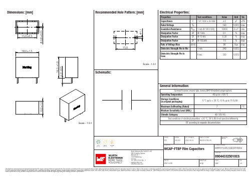
Dimensions: [mm]MPPP015225J160DCPP45004890443325010CSMPPP015225J160DCPP45004 890443325010CSMPPP015225J160DCPP45004 890443325010CSMPPP015225J160DCPP45004 890443325010CST e m p e r a t u r eT T T MPPP015225J160DCPP45004890443325010CSCautions and Warnings:The following conditions apply to all goods within the product series of Film Capacitors of Würth Elektronik eiSos GmbH & Co. KG:General:•This electronic component is designed and manufactured for use in general electronic equipment.•Würth Elektronik must be asked for a written approval (following the certain PPAP level procedure) before incorporating the components into any equipment in the field such as military, aerospace, aviation, nuclear control, submarine, transportation (automotive control, train control, ship control), transportation signal, disaster prevention, medical, public information network etc. where higher safety and reliability are especially required and/or if there is the possibility of direct damage or human injury.•Electronic components that will be used in safety-critical or high-reliability applications, should be pre-evaluated by the customer. •Direct mechanical impact to the product shall be prevented as material of the body, pins or termination could flake or in the worst case it could break.•Avoid any water or heavy dust on capacitors surface, which may cause electrical leakage, damage, overheating or corrosion.•Würth Elektronik products are qualified according to international standards, which are listed in each product reliability report. Würth Elektronik does not warrant any customer qualified product characteristic, beyond Würth Elektronik specifications, for its validity and sustainability over time.•The customer is responsible for the functionality of his or her own products. All technical specifications for standard products also apply to customer specific products.•The component is designed and manufactured to be used within the datasheet specified values. If the usage and operation conditions specified in the datasheet are not met, the body, pins or termination may be damaged or dissolved.•Do not apply any kind of flexural or compressive force onto soldered or unsoldered component.•The capacitance tolerance as specified within the datasheet is only valid on the date of delivery and according specified measurement criteria.Product specificStorage conditions• A storage of Würth Elektronik products for longer than 12 months is not recommended. Within other effects, the terminals may suffer degradation, resulting in bad solderability. Therefore, all products shall be used within the period of 12 months based on the day of shipment.•Do not expose the components into direct sunlight.•The storage condition in the original packaging is defined according to DIN EN 61760-2.•The environment in which the capacitors are operated and stored has to have atmospheric characteristics and must be free of dew condensation and toxic gases (e.g. chlorine, ammonia, sulfur, hydrogen sulphide and hydrogen sulfate).•Do not expose the capacitor to environments with hazardous gas, ozone, ultraviolet rays or any kind of radiation. Avoid any contact of the capacitor with direct sunshine, saltwater, spray of water or types of oil during storage. •The storage conditions stated in the original packaging apply to the storage time and not to the transportation time of the components. Operating climatic conditions•Do not exceed the lower nor the upper specified temperature under no circumstances.•Do not use the capacitors under high humidity, high temperature or under high or low atmospheric pressure which may affect capacitors reliability.•Surface temperature including self-heating must be kept below the maximum operating temperature.Operating load conditions•Due to self-heating the reliability of the capacitor may be reduced, if high frequency AC or pulse is applied.•Consider carefully possible specific changes of electrical characteristics like capacitance over temperature, voltage and time as well as the specific performance over frequency for the actual use conditions.•Avoid any overvoltage and do not apply a continuous overvoltage. If an overvoltage is applied to the capacitor, the leakage current can increase drastically. The applied working voltage is not allowed to exceed the rated working voltage of the specific capacitor.•If film capacitors with safety approvals are operated with a DC voltage exceeding the specified AC voltage, the approvals given on the basis of IEC 60384-14 are no longer valid.Packaging:•The packaging specifications apply only to purchase orders comprising whole packaging units. If the ordered quantity exceeds or is lower than the specified packaging unit, packaging in accordance with the packaging specifications cannot be ensured. Soldering•The solder profile must comply with the Würth Elektronik technical soldering specification. All other profiles will void the warranty. •All other soldering methods are at the customer’s own risk.•Strong forces which may affect the coplanarity of the component’s electrical connection with the PCB (i.e. pins), can damage the part, resulting in void of the warranty.•Customer needs to ensure that the applied solder paste, the paste thickness and solder conditions are enough to guarantee a sufficient solder result according to the relevant criteria of IPC-A-610.•Excessive amount of solder may lead to higher tensile force and chip cracking. Insufficient amount of solder may detach the capacitor due to defective contacts.•Do not use excessive nor insufficient flux.Cleaning•Do not use any other cleaning solvents for box-typed capacitors except: ethanol, isopropanol, n-propanol - water mixtures. After cleaning a drying process with temperatures not exceeding 65°C and not longer than 4 hours is mandatory to prevent any kind ofelectrical damage.Würth Elektronik eiSos GmbH & Co. KGEMC & Inductive SolutionsMax-Eyth-Str. 174638 WaldenburgGermanyCHECKED REVISION DATE (YYYY-MM-DD)GENERAL TOLERANCE PROJECTIONMETHODFPh002.0012022-08-01DIN ISO 2768-1mDESCRIPTION TECHNICAL REFERENCEWCAP-FTBP Film Capacitors MPPP015225J160DCPP45004ORDER CODE890443325010CSSIZE/TYPE BUSINESS UNIT STATUS PAGECoating, molding and potting of the PCB•If the product is potted in the costumer’s application, the potting material might shrink or expand during and after hardening. Shrinking could lead to an incomplete seal, allowing contaminants into the body and termination. Expansion could damage the body or termination. We recommend a manual inspection after potting to avoid these effects.•If final assemblies will be placed completely in any plastic resin, physical, chemical and thermal influences must be considered. •When coating and molding the PCB, verify the quality influence on the capacitor.•Verify the curing temperature and assure that there is no harmful decomposing or reaction gas emission during curing. •Do not exceed the specified max. self-heating.Vibration resistance•Do not exceed the vibration limits given by IEC60068-2-6.Handling•After soldering, please pay attention not to bend, twist or distort the PCB in handling and storage. •Avoid excessive pressure during the functional check of the PCB. •Avoid bending stress while breaking the PCB.•WCAP-FTXX and WCAP-FTX2 capacitors are not designed and not recommended to be used in series connection to the mains. •The temperature rise of the component must be taken into consideration. The operating temperature is comprised of ambient temperature and temperature rise of the component.The operating temperature of the component shall not exceed the maximum temperature specified.Flammability•Avoid any external energy or open fire (passive flammability).These cautions and warnings comply with the state of the scientific and technical knowledge and are believed to be accurate and reliable.However, no responsibility is assumed for inaccuracies or incompleteness.(V2.1)Würth Elektronik eiSos GmbH & Co. KG EMC & Inductive Solutions Max-Eyth-Str. 174638 Waldenburg GermanyCHECKED REVISION DATE (YYYY-MM-DD)GENERAL TOLERANCEPROJECTION METHODFPh002.0012022-08-01DIN ISO 2768-1mDESCRIPTIONTECHNICAL REFERENCEWCAP-FTBP Film CapacitorsMPPP015225J160DCPP45004ORDER CODE890443325010CSSIZE/TYPEBUSINESS UNITSTATUSPAGEImportant NotesThe following conditions apply to all goods within the product range of Würth Elektronik eiSos GmbH & Co. KG:1. General Customer ResponsibilitySome goods within the product range of Würth Elektronik eiSos GmbH & Co. KG contain statements regarding general suitability for certain application areas. These statements about suitability are based on our knowledge and experience of typical requirements concerning the areas, serve as general guidance and cannot be estimated as binding statements about the suitability for a customer application. The responsibility for the applicability and use in a particular customer design is always solely within the authority of the customer. Due to this fact it is up to the customer to evaluate, where appropriate to investigate and decide whether the device with the specific product characteristics described in the product specification is valid and suitable for the respective customer application or not.2. Customer Responsibility related to Specific, in particular Safety-Relevant ApplicationsIt has to be clearly pointed out that the possibility of a malfunction of electronic components or failure before the end of the usual lifetime cannot be completely eliminated in the current state of the art, even if the products are operated within the range of the specifications.In certain customer applications requiring a very high level of safety and especially in customer applications in which the malfunction or failure of an electronic component could endanger human life or health it must be ensured by most advanced technological aid of suitable design of the customer application that no injury or damage is caused to third parties in the event of malfunction or failure of an electronic component. Therefore, customer is cautioned to verify that data sheets are current before placing orders. The current data sheets can be downloaded at .3. Best Care and AttentionAny product-specific notes, cautions and warnings must be strictly observed. Any disregard will result in the loss of warranty.4. Customer Support for Product SpecificationsSome products within the product range may contain substances which are subject to restrictions in certain jurisdictions in order to serve specific technical requirements. Necessary information is available on request. In this case the field sales engineer or the internal sales person in charge should be contacted who will be happy to support in this matter.5. Product R&DDue to constant product improvement product specifications may change from time to time. As a standard reporting procedure of the Product Change Notification (PCN) according to the JEDEC-Standard inform about minor and major changes. In case of further queries regarding the PCN, the field sales engineer or the internal sales person in charge should be contacted. The basic responsibility of the customer as per Section 1 and 2 remains unaffected.6. Product Life CycleDue to technical progress and economical evaluation we also reserve the right to discontinue production and delivery of products. As a standard reporting procedure of the Product Termination Notification (PTN) according to the JEDEC-Standard we will inform at an early stage about inevitable product discontinuance. According to this we cannot guarantee that all products within our product range will always be available. Therefore it needs to be verified with the field sales engineer or the internal sales person in charge about the current product availability expectancy before or when the product for application design-in disposal is considered. The approach named above does not apply in the case of individual agreements deviating from the foregoing for customer-specific products.7. Property RightsAll the rights for contractual products produced by Würth Elektronik eiSos GmbH & Co. KG on the basis of ideas, development contracts as well as models or templates that are subject to copyright, patent or commercial protection supplied to the customer will remain with Würth Elektronik eiSos GmbH & Co. KG. Würth Elektronik eiSos GmbH & Co. KG does not warrant or represent that any license, either expressed or implied, is granted under any patent right, copyright, mask work right, or other intellectual property right relating to any combination, application, or process in which Würth Elektronik eiSos GmbH & Co. KG components or services are used.8. General Terms and ConditionsUnless otherwise agreed in individual contracts, all orders are subject to the current version of the “General Terms and Conditions of Würth Elektronik eiSos Group”, last version available at .Würth Elektronik eiSos GmbH & Co. KGEMC & Inductive SolutionsMax-Eyth-Str. 174638 WaldenburgGermanyCHECKED REVISION DATE (YYYY-MM-DD)GENERAL TOLERANCE PROJECTIONMETHODFPh002.0012022-08-01DIN ISO 2768-1mDESCRIPTION TECHNICAL REFERENCEWCAP-FTBP Film Capacitors MPPP015225J160DCPP45004ORDER CODE890443325010CSSIZE/TYPE BUSINESS UNIT STATUS PAGE。
斯奎特电源入口模块与电线滤波器FKHD说明书

1IEC Appliance Inlet C14 with Filter 2-Stage, Fuseholder 1-pole, Line Switch 2-poleSee below:Approvals and CompliancesC1470° CDescription- Panel mount :Screw-on mounting from front side - 4 Functions :Appliance Inlet Protection class I , Fuseholder for fuse-links 5 x 20 mm 1-pole , Line Switch 2-pole , Line-filter in standard version , 2 positions - Quick connect terminals 6.3 x 0.8 mmCharacteristics- Compact design with optimal shielding - All single elements are already wired- Plug removal necessary for fuse-link replacement - 2-stage line filter with increased attenuation With EMC-shield- Suitable for use in equipment according to IEC/UL 60950Suitable for use in medical equipment according to IEC/UL 60601-1Other versions on request- Medical version M80References Alternative: version with 1-stage filter FKHWeblinkspdf datasheet , html-datasheet , General Product Information , Distributor-Stock-Check , Accessories , Detailed request for productT echnical DataRatings IEC1 - 10 A @ Ta 40 °C / 250 VAC; 50 Hz Ratings UL/CSA 1 - 10 A @ Ta 40 °C / 125 VAC; 60 Hz Leakage Current standard < 0.5 mA (250 V / 60 Hz)Dielectric Strength> 1.7 kVDC between L-N > 2.7 kVDC between L/N-PE Test voltage (2 sec)Allowable Operation Tempe-rature-25 °C to 85 °CClimatic Category 25/085/21 acc. to IEC 60068-1IP-Protection from front side IP 40 acc. to IEC 60529Protection Class Suitable for appliances with protection class I acc. to IEC 61140TerminalQuick connect terminals 6.3 x 0.8 mm Panel Thickness S Screw: max 8 mmMounting screw torque max 0.5 Nm Material: HousingThermoplastic, black, UL 94V-0appliance inlet/-outletC14 acc. to IEC 60320-1,UL 498, CSA C22.2 no. 42 (for cold conditions) pin-temperature 70 °C, 10 A, Protection Class IFuseholder1-pole, Shocksafe category PC2 acc. to IEC 60127-6,for fuse-links 5 x 20 mm Rated Power Acceptance @ Ta 23 °C5 x 20: 1.6 W (1 pole)Power Acceptance @ Ta > 23°C Admissible power acceptance at higher ambient temperature see derating cur-vesLine Switch2-pole, non-illuminated, acc. to IEC 61058-1Technical DetailsLine FilterStandard Version, IEC 60939, UL 1283, CSA C22.2 no. 8 Technical DetailsMTBF> 1'200'000 h acc. to MIL-HB-217 FApprovals and CompliancesDetailed information on product approvals, code requirements, usage instructions and detailed test conditions can be looked up in Details about ApprovalsSCHURTER products are designed for use in industrial environments. They have approvals from independent testing bodies according to national and international standards. Products with specific characteristics and requirements such as required in the automotive sector according to IATF 16949, medical technology according to ISO 134485 or in the aerospace industry can be offered exclusively with customer-specific, individual agree-ments by SCHURTER.ApprovalsThe approval mark is used by the testing authorities to certify compliance with the safety requirements placed on electronic products. Approval Reference T ype: FKHDApproval Logo Certificates Certification Body DescriptionVDE Approvals VDE Certificate Number: 40004665UL Approvals UL UL File Number: E72928Product standardsProduct standards that are referencedOrganization Design StandardDescriptionDesigned according to IEC 60320-1Appliance couplers for household and similar general purposesDesigned according to IEC 60939Passive filters for suppressing electromagnetic interferenceDesigned according to IEC 60127-6Miniature fuses. Part 6. Fuse-holders for miniature fuse-linksDesigned according to IEC 61058-1Switches for appliances. Part 1. General requirements Designed according to UL 498Standard for Attachment Plugs and ReceptaclesDesigned according to UL 1283Electromagnetic interference filtersDesigned according to CSA C22.2 no. 42General Use Receptacles, Attachment Plugs, and Similar Wiring DevicesDesigned according to CSA C22.2 no. 8Electromagnetic interference (EMI) filters Application standardsApplication standards where the product can be usedOrganization Design StandardDescriptionDesigned for applications acc.IEC/UL 60950IEC 60950-1 includes the basic requirements for the safety of informationtechnology equipment.Designed for applications acc.IEC 60601-1Medical electrical equipment - Part 1: General requirements for basicsafety and essential performanceDesigned for applications acc.IEC 60335-1Safety of electrical appliances for household and similar purposes. Meetsthe requirements for appliances in unattended use. This includes the en-hanced requirements of glow wire tests acc. to IEC 60695-2-12 and -13. CompliancesThe product complies with following Guide LinesIdentification Details Initiator DescriptionCE declaration of conformity SCHURTER AG The CE marking declares that the product complies with the applicablerequirements laid down in the harmonisation of Community legislation onits affixing in accordance with EU Regulation 765/2008.RoHS SCHURTER AG EU Directive RoHS 2011/65/EUChina RoHS SCHURTER AG The law SJ / T 11363-2006 (China RoHS) has been in force since 1 March2007. It is similar to the EU directive RoHS.REACH SCHURTER AG On 1 June 2007, Regulation (EC) No 1907/2006 on the Registration,Evaluation, Authorization and Restriction of Chemicals 1 (abbreviated as"REACH") entered into force.White paper Glow wire test SCHURTER AG Meets the requirements of IEC 60335-1 for appliances in unattended use.This includes the enhanced requirements of glow wire tests acc. to IEC60695-2-12 and -13.Medical Equipment SCHURTER AG Suitable for use in medical equipment according to IEC/UL 60601-123Dimension [mm]Case 45Diagrams Standard versionNLPE’L’1)2)1) Line2) Load Medical version (M5)LPE’L’1)2)1) Line 2) LoadDerating Curves 1-poleA d m i s s i b l e p o w e r a c c e p t a n c e i n W a t tAmbient air temperature Ta °C4Attenuation Loss- - - - 50Ω differential mode _____ 50Ω common modeStandard version1 A2 A4 A6 A10 AMedical version (M5)1 A2 A4 A6 A10 AAll VariantsPackaging unit 10 Pcs AccessoriesDescriptionAssorted CoversRear Cover0859.0074Mating Outlets/ConnectorsCategory / DescriptionAppliance Outlet Overview completeIEC Appliance Outlet F, Screw-on Mounting, Front Side, Solder Terminal4787IEC Appliance Outlet F, Snap-in Mounting, Front Side, Solder or Quick-connect Terminal4788IEC Appliance Outlet F or H, Screw-on Mounting, Front Side, Solder, PCB or Quick-connect Terminal5091Appliance Outlet further types to FKHDConnector Overview complete4782 Mounting: Power Cord, 3 x 1 mm² / 3 x 18 AWG, Cable, Connector: IEC C1347824785 Mounting: Power Cord, 3 x 1 mm² / 3 x 18 AWG, Cable, Connector: IEC C1347854300-06 Mounting: Power Cord, 3 x 1 mm² / 3 x 18 AWG, Cable, Connector: IEC C134300-06IEC Connector C15 for hot conditions 120°C, Rewireable, Straight4781IEC Connector C15 for hot conditions 120°C, Rewireable, Angled4784Connector further types to FKHD...The specifications, descriptions and illustrations indicated in this document are based on currentinformation. All content is subject to modifications and amendments. Information furnished is believed18.12.2185。
Philips 电子剃须刀Series 5000 产品说明说明书

S5898/50shave, gentle on skinwith SkinIQ T echnologyThe Philips Series 5000 delivers a powerful shave, cutting now even more hair perstroke*. Equipped with advanced SkinIQ technology, the shaver senses andadapts to your hair density, for improved skin comfort.A powerful shavePowerful performance in every passEngineered for precision and cutting efficiencyFlexible heads follow your facial contoursSkinIQ technologyA djusts to your beard for effortless shavingFor a convenient shaveDeep cleaning in just 1 minute for hygienic shavingUp to 60 minutes of cordless shaving when fully charged1 hour charging time and 5 min quick chargeLED display with icons to use the shaver intuitivelyShave wet, dry and even under the showerPrecision trimmer integrated in the handleSustainabilityConvenient chargingHighlightsSteelPrecisionbladesWith up to 90,000 cutting actions per minute , the SteelPrecision blades shave close , cutting more hair per stroke *. The 45high -performance blades are self -sharpening and made in Europe .Power A daptsensorThe intelligent facial -hair sensor reads hair density 500 times per second . Thetechnology auto -adapts cutting power for an e ffortless and gentle shave .360 D FlexingheadsFully flexible heads turn 360° to follow your facial contours . Experience optimal skin contact for a thorough and comfortable shave .Hair -Guide PrecisionheadsThe new shape of the shaving heads is engineered for precision . The surface is enhanced with hair guiding channels ,designed to move hair into an e ffective cutting position .Cable -free Quick CleanPodPowerful cleaning pod thoroughly cleans and lubricates your shaver in just 1 minute ,keeping it performing at its best for longer .The pod is 10 x more e ffective than cleaning with water **. It is the world 's smallestcleaning pod , so you can store it easily and use it anywhere .Wet andDryA dapt your shaving routine to your needs .With Wet and Dry , you can go for acomfortable dry shave or a refreshing wet shave . Y ou can shave with gel or foam , even under the shower .Pop -uptrimmerComplete your look using the shaver 's pop -up precision trimmer . Integrated into the shaver 's body , it 's the perfect way tomaintain a moustache and trim sideburns .60 minutes of cordlessshavingShave cordlessly for up to 60 minutes after one full battery charge .1 hour chargingtimeCharge your shaver fully in just 1 hour with the powerful and energy e fficient lithium -ion battery . In a hurry ? Plug in your shaver for 5 minutes and get enough power for 1 full shave .SpecificationsShaving PerformanceContour following: 360 D Flexing heads Shaving system: SteelPrecision blades SkinIQ technology: Power A dapt sensor DesignHandle: Rubber gripColour: Deep BlackShaving heads: A ngularA ccessoriesMaintenance: Cleaning brushQuick Clean Pod: Y es, 1 cartridge included Integrated pop-up trimmerTravel and storage: Travel case Ease of useDisplay: LED display, Battery level indicator,Travel lockWet and Dry: Wet and dry useCharging: USB-A ChargingCleaning: One-touch open, Fully washablePowerCharging: 1 hour full charge, 5-min quickchargeBattery Type: Li-IonA utomatic voltage: 5 VRun time: 60 minutesStand-by power: 0.04 WMax power consumption: 9 WService2 year warrantyReplacement head SH71: Replace every 2 yrswith SH71A ccessoriesUSB-A cable included: Power adapter notincluded* Tested versus Philips Series 3000.* *comparing shaving debris after using cleaning fluid vs.water in the cartridge© 2022 Koninklijke Philips N.V.A ll Rights reserved.Specifications are subject to change without notice. Trademarks are the property of Koninklijke Philips N.V. or their respective owners.Issue date 2022‑12‑22 Version: 8.8.1。
- 1、下载文档前请自行甄别文档内容的完整性,平台不提供额外的编辑、内容补充、找答案等附加服务。
- 2、"仅部分预览"的文档,不可在线预览部分如存在完整性等问题,可反馈申请退款(可完整预览的文档不适用该条件!)。
- 3、如文档侵犯您的权益,请联系客服反馈,我们会尽快为您处理(人工客服工作时间:9:00-18:30)。
4 Power – Diesel engines for power generation
Prime Power (PRP) nnPower output available with varying load for
unlimited time. Average power output is 80 % of the prime power rating. nnWith 10 % overload capability for technical purposes for a maximum of one hour in twelve. Overload operation cannot exceed 50 hours per year. nnPrime power in accordance with ISO 8528. nnFuel stop power in accordance with ISO 3046.
Customer Benefits nnMAN is a strong and independent partner for
packagers and offers high quality engines made in Germany
nnGlobal after sales network guarentees short-term spare parts supply
COP
180 –220 220–265 270 –283 270 – 350 310 – 435 390–530 525–640
Emergency Standby Power (ESP) nnPower output available with varying load for
the duration of an emergency outage. Average power output is 70 % of the emergency standby power rating. nnTypical operation is 50 hours per year with maximum expected usage of 200 hours per year. nnStandby power in accordance with ISO 8528. nnFuel stop power in accordance with ISO 3046.
12.8
451–507
12.4
415–440
14.6
4951.9
633–800
24.2 880–1 117
Power rating (kW)
LTP
PRP
308–354 391–446
396 446–506 496–622 597–765 770 – 880
280–322 355–405 36 0 – 377 405–460 451–565 543–695 70 0 – 80 0
Limited Time Power (LTP) nnPower output available with varying load for
the duration of the interruption of the normal source power. nnTypical operation is 200 hours per year, with maximum expected usage of 500 hours per year, within the following limits of maximum operating time: 100 % load 50 hours per year and 90 % load 200 hours per year. nnNo overload available. nnFuel stop power in accordance with ISO 3046.
Power – Diesel engines for power generation 3
MAN diesel engines for power generation Application type and product range
Product range overview
Diesel engines for ESP, LTP, PRP and COP
Application type and product range . . . . . . . . . . . . . . . . . . . . . . . . . . . . . . . . . . . . . . . . . 4
nnEco-friendly operation as a result of lower consumption of fuel and lubricating oil
nnMAN engines with high efficiency, reliability and low maintenace costs result in profitable prime power operation especially in emerging markets
nnMAN engines for standby operation to provide maximum power output with quick load acceptance in case of power shortage
nnIdeal balance between compact design and robust construction allows smaller size of container gensets with high durability
MAN diesel engines for power generation Power wherever needed
MAN offers manufacturers of power generators all over the world a broad spectrum of 6-, 8-, 10- and 12-cylinder engines including radiators for peak load leveling as well as for supplying emergency power and base loads. Depending on their type of operation in PRP (Prime Power), ESP (Emergency Standby Power), COP (Continuous Power) or LTP (Limited Time Power), the engines can be run for a maximum of between 200 and 8 000 hours a year. Totally reliable and with dependable availability and exemplary economy, they provide limitless energy generation. Transforming night into day.
Servicing concept
MAN offers power-unit manufacturers a tailor-made servicing concept. This is how MAN gives you the option of performing servicing for your end customers yourself, from start to finish. This is made possible by an extensive training offering which can be matched individually to your needs.
Engine type Cylinder(s) Arrangement Capacity (l)
ESP
D2866 D2876 D2676 D2848 D2840 D2842 D2862
6
in-line
6
in-line
6
in-line
8
V 90°
10
V 90°
12
V 90°
12
V 90°
11.9
360–400
Power generation
Power
P ower
Diesel engines for power generation
M AN Engines
A Division of MAN Truck & Bus
Contents
MAN diesel engines for power generation . . . . . . . . . . . . . . . . . . . . . . . . . . . . . . . . . . . . 3
Description of engines D2866 . . . . . . . . . . . . . . . . . . . . . . . . . . . . . . . . . . . . . . . . . . . . . . . . . . . . . . . . . . . . . . . . . 6 D2876 . . . . . . . . . . . . . . . . . . . . . . . . . . . . . . . . . . . . . . . . . . . . . . . . . . . . . . . . . . . . . . . . . . 8 D2676 . . . . . . . . . . . . . . . . . . . . . . . . . . . . . . . . . . . . . . . . . . . . . . . . . . . . . . . . . . . . . . . . . 10 D2848 . . . . . . . . . . . . . . . . . . . . . . . . . . . . . . . . . . . . . . . . . . . . . . . . . . . . . . . . . . . . . . . . . 12 D2840 . . . . . . . . . . . . . . . . . . . . . . . . . . . . . . . . . . . . . . . . . . . . . . . . . . . . . . . . . . . . . . . . 14 D2842 . . . . . . . . . . . . . . . . . . . . . . . . . . . . . . . . . . . . . . . . . . . . . . . . . . . . . . . . . . . . . . . . 17 D2862 . . . . . . . . . . . . . . . . . . . . . . . . . . . . . . . . . . . . . . . . . . . . . . . . . . . . . . . . . . . . . . . . . 20