计算机网络课程设计实验_动态路由配置
动态路由配置实验

动态路由配置实验(学时数:4,分两次完成)一、实验目的1、掌握在一个网络系统中配置动态路由RIP二、实验设备及环境Star-R2620路由器四台,计算机四台,Star-1926F+交换机一台 ● 网络拓朴结构●各主机和路由器接口的IP 地址各路由器的接口IP 地址分配如下:各主机的IP地址和缺省网关分配如下:三、知识点说明1、动态路由协议RIP●RIP的概念RIP(Routing Information Protocol,路由信息协议)是一种有类别的、距离向量路由协议。
RIP使用非常简单的度量值一跳数(HOPS),仅考虑到达目的网络要经过的路由器个数,不考虑路径的带宽和其他因素。
跳数的计算是将指定路由器到达远程网络所有路由器的个数进行简单相加而完成的。
每隔30秒广播一次路由表,维护相邻路由器的关系,同时根据收到的路由表计算自己的路由表。
RIP运行简单,适用于小型网络。
●RIP的配置方法RIP路由协议原理看起来很复杂,然而配置RIP是相当简单的,主要有以下两个步骤:①启动RIP路由进程。
在全局配置模式下,使用“router rip”命令。
②在路由配置模式下配置路由器的那些接口参与RIP进程。
使用“network主网络号”命令举例如下:RTA(config)#router ripRTA(config-router)#network 192.168.1.0RTA(config-router)#network 192.168.3.0RTA(config-router)#network 192.168.7.0使用“network”命令时,网络号应是路由器的直连接口的主网络号。
RTA直连接网络192. 168.1.0/24的主网络号为192.168.1.0,而另外两个直连网络的主网络号分别为192.168.3.0,192.168.7.0。
四、实验内容1、配置动态路由协议RIP●RTA的配置Red-Giant>enRed-Giant#config tRed-Giant (config)#hostname RTARTA(config)#int f0RTA(config-if)#ip address 192.168.7.1 255.255.255.0RTA(config-if)#no shutdownRTA(config-if)#exitRTA(config)#int s0RTA(config-if)#ip address 192.168.1.1 255.255.255.0RTA(config-if)#encapsulation pppRTA(config-if)#clock rate 2000000RTA(config-if)#no shutdownRTA(config-if)#exitRTA(config)#int s1RTA(config-if)#ip address 192.168.3.2 255.255.255.0RTA(config-if)#encapsulation pppRTA(config-if)#no shutdownRTA(config-if)#exitRTA(config)#router ripRTA(config-router)#network 192.168.1.0RTA(config-router)#network 192.168.3.0RTA(config-router)#network 192.168.7.0RTD(config-router)#exitRTA(config)#exitRTA#writeRTA#show runRTA# show ip routeRTB的配置Red-Giant>enRed-Giant#config tRed-Giant (config)#hostname RTBRTB(config)#int f0RTB(config-if)#ip address 192.168.4.1 255.255.255.0RTB(config-if)#no shutdownRTB(config-if)#exitRTB(config)#int s0RTB(config-if)#ip address 192.168.1.2 255.255.255.0RTB(config-if)#encapsulation pppRTB(config-if)#no shutdownRTB(config-if)#exitRTB(config)#int s1RTB(config-if)#ip address 192.168.2.1 255.255.255.0RTB(config-if)#clock rate 2000000RTB(config-if)#encapsulation pppRTB(config-if)#no shutdownRTB(config-if)#exitRTB(config)#router ripRTB(config-router)#network 192.168.1.0RTB(config-router)#network 192.168.2.0RTB(config-router)#network 192.168.4.0RTD(config-router)#exitRTB(config)#exitRTB#writeRTB#show runRTB# show ip route●RTC的配置Red-Giant>enRed-Giant#config tRed-Giant (config)#hostname RTCRTC(config)#int f0RTC(config-if)#ip address 192.168.6.1 255.255.255.0RTC(config-if)#no shutdownRTC(config-if)#exitRTC(config)#int s0RTC(config-if)#ip address 192.168.2.2 255.255.255.0RTC(config-if)#encapsulation pppRTC(config-if)#no shutdownRTC(config-if)#exitRTC(config)#int s1RTC(config-if)#ip address 192.168.3.1 255.255.255.0RTC(config-if)#clock rate 2000000RTC(config-if)#encapsulation pppRTC(config-if)#no shutdownRTC(config-if)#exitRTC(config)#router ripRTC(config-router)#network 192.168.2.0RTC(config-router)#network 192.168.3.0RTC(config-router)#network 192.168.6.0RTD(config-router)#exitRTC(config)#exitRTC#writeRTC#show runRTC# show ip route●RTD的配置Red-Giant>enRed-Giant#config tRed-Giant (config)#hostname RTDRTD(config)#int f0RTD(config-if)#ip address 192.168.4.2 255.255.255.0RTD(config-if)#no shutdownRTD(config-if)#exitRTD(config)#int f1RTD(config-if)#ip address 192.168.5.1 255.255.255.0RTD(config-if)#no shutdownRTD(config-if)#exitRTD(config)#router ripRTD(config-router)#network 192.168.4.0RTD(config-router)#network 192.168.5.0RTD(config-router)#exitRTD(config)#exitRTD#writeRTD#show runRTD# show ip route五、思考题a)如果本实验网络系统只用静态路由来实现,RTA、RTB、RTC、RTD应分别如何配置?b)配置RIP路由有哪些命令?分别在什么模式下输入这些命令?c)配置OSPF路由有哪些命令?分别在什么模式下输入这些命令?。
实验四 静态路由和动态路由配置

实验四静态路由和动态路由配置【实验目的】通过本实验初步掌握网络互连的组网方法、基本配置和操作技能,掌握组建企业网广域互连网络的应用技能,包括如下几个方面:✓掌握路由器的基本配置方法。
✓了解IP地址和子网的管理方法。
✓掌握广域互连网络的基本组网方法。
✓掌握静态路由的基本配置方法。
✓掌握动态路由的基本配置方法。
实验前学生应具备以下知识:✓了解路由器的工作原理和组网特点。
✓了解路由器的安装和配置。
✓了解IP地址和子网的划分方法。
✓了解动态路由协议的原理和特点。
实验过程中,部分实验内容需要与相邻的同学配合完成。
此外,学生需要将实验的结果记录下来,并回答相关思考题,填写到实验报告中。
【实验类型】综合型实验【实验环境】实验设备:交换机S2403H两台、S3050一台;路由器R1602六台。
实验组成:每排为一组,各使用一台路由器。
实验网络结构图参见实验内容。
【实验内容】以下实验内容可根据实验室的具体情况和课时安排的变化进行适当的调整,实验内容中的思考题以书面形式解答并附在实验报告的后面。
需要注意的是,学生在实验过程中要严格按实验指导书的操作步骤和要求操作,且小组成员应紧密配合,以保证实验过程能够顺利完成。
本次实验的主要项目包括以下几个方面:☑路由器的基本配置方法☑配置静态路由;☑配置RIP动态路由;☑配置OSPF动态路由;☑TCP/IP测试。
具体的实验内容和步骤如下:一、实验环境简介实验环境模拟一个较大的企业网络,网络结构如图1,设备组成有:S2403H两台、S3050一台;R1602六台。
其中S2403H和S3050为模拟企业局域网连接的交换机,广域PPP/HDLC 连接采用背靠背连接模拟。
图1 企业网互连图2 实验室布局图3 IP地址和子网设计二、路由器基本配置1.设备简介Quidway R1602路由器具有一个RJ-45 Ethernet 接口,两个同/异步串口,一个备份口。
用户可在PSTN/ISDN、Frame Relay、X.25和DDN等多种广域网技术中,灵活选择组网方案。
PT 实验(九) 路由器RIP动态路由配置
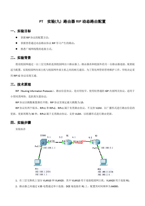
PT 实验(九) 路由器RIP动态路由配置一、实验目标●掌握RIP协议的配置方法;●掌握查看通过动态路由协议RIP学习产生的路由;●熟悉广域网线缆的连接方式;二、实验背景假设校园网通过一台三层交换机连到校园网出口路由器上,路由器再和校园外的另一台路由器连接。
现要做适当配置,实现校园网内部主机与校园网外部主机之间的相互通信。
为了简化网管的管理维护工作,学校决定采用RIP V2协议实现互通。
三、技术原理RIP(Routing Information Protocols),路由信息协议,是应用较早、使用较普通的IGP内部网关协议,适用于小型同类网络,是距离矢量协议;RIP协议以跳数衡量路径开销,RIP协议里规定最大跳数为15;RIP协议有两个版本:RIPv1和RIPv2,RIPv1属于有类路由协议,不支持VLSM,以广播形式进行路由信息的更新,更新周期为30秒;RIPv2属于无类路由协议,支持VLSM,以组播形式进行路由更新。
四、实验步骤实验拓扑1、在三层交换机上划分VLAN10和VLAN20,其中VLAN10用于连接校园网主机,VLAN20用于连接R1;2、路由器之间通过V.35电缆通过串口连接,DCE端连接在R1上,配置其时间频率为64000;3、主机和交换机通过直连线连接,主机与路由器通过交叉线连接;4、在S3560上配置RIPv2路由协议;5、在路由器R1、R2上配置RIPv2路由协议;6、将PC1、PC2主机默认网关分别设置为与直连网络设备接口IP地址;7、验证PC1、PC2主机之间可以互相通信;S3560:Switch>Switch>enSwitch#conf tEnter configuration commands, one per line. End with CNTL/Z.Switch(config)#hostname S3560S3560(config)#vlan 10S3560(config-vlan)#exitS3560(config)#vlan 20S3560(config-vlan)#exitS3560(config)#interface fa0/10S3560(config-if)#switchport access vlan 10S3560(config-if)#exitS3560(config)#interface fa0/20S3560(config-if)#switchport access vlan 20S3560(config-if)#exitS3560(config)#interface vlan 10%LINK-5-CHANGED: Interface Vlan10, changed state to up%LINEPROTO-5-UPDOWN: Line protocol on Interface Vlan10, changed state to up S3560(config-if)#ip address 192.168.1.1 255.255.255.0S3560(config-if)#exitS3560(config)#interface vlan 20%LINK-5-CHANGED: Interface Vlan20, changed state to upS3560(config-if)#ip address 192.168.3.1 255.255.255.0S3560(config-if)#exitS3560#%SYS-5-CONFIG_I: Configured from console by consoleS3560#show ip routeCodes: C - connected, S - static, I - IGRP, R - RIP, M - mobile, B - BGPD - EIGRP, EX - EIGRP external, O - OSPF, IA - OSPF inter areaN1 - OSPF NSSA external type 1, N2 - OSPF NSSA external type 2E1 - OSPF external type 1, E2 - OSPF external type 2, E - EGPi - IS-IS, L1 - IS-IS level-1, L2 - IS-IS level-2, ia - IS-IS inter area* - candidate default, U - per-user static route, o - ODRP - periodic downloaded static routeGateway of last resort is not setC 192.168.1.0/24 is directly connected, Vlan10S3560(config)#router rip //配置rip路由协议S3560(config-router)#network 192.168.1.0S3560(config-router)#network 192.168.3.0S3560(config-router)#version 2S3560(config-router)#endS3560#%LINK-5-CHANGED: Interface FastEthernet0/20, changed state to up%LINEPROTO-5-UPDOWN: Line protocol on Interface FastEthernet0/20, changed state to up %LINEPROTO-5-UPDOWN: Line protocol on Interface Vlan20, changed state to up //当配置好所有RIPv2后,再查看路由信息S3560#show ip routeCodes: C - connected, S - static, I - IGRP, R - RIP, M - mobile, B - BGPD - EIGRP, EX - EIGRP external, O - OSPF, IA - OSPF inter areaN1 - OSPF NSSA external type 1, N2 - OSPF NSSA external type 2E1 - OSPF external type 1, E2 - OSPF external type 2, E - EGPi - IS-IS, L1 - IS-IS level-1, L2 - IS-IS level-2, ia - IS-IS inter area* - candidate default, U - per-user static route, o - ODRP - periodic downloaded static routeGateway of last resort is not setC 192.168.1.0/24 is directly connected, Vlan10R 192.168.2.0/24 [120/2] via 192.168.3.2, 00:00:01, Vlan20C 192.168.3.0/24 is directly connected, Vlan20R 192.168.4.0/24 [120/1] via 192.168.3.2, 00:00:01, Vlan20S3560#R1:Router>enRouter#conf tEnter configuration commands, one per line. End with CNTL/Z.Router(config)#hostname R1R1(config)#interface fa0/0R1(config-if)#ip address 192.168.3.2 255.255.255.0R1(config-if)#no shutdown%LINK-5-CHANGED: Interface FastEthernet0/0, changed state to up%LINEPROTO-5-UPDOWN: Line protocol on Interface FastEthernet0/0, changed state to up R1(config-if)#exitR1(config)#interface serial 0/0R1(config-if)#ip address 192.168.4.1 255.255.255.0R1(config-if)#no shutdown%LINK-5-CHANGED: Interface Serial0/0, changed state to downR1(config-if)#clock rate 64000R1(config-if)#exitR1#show ip routeCodes: C - connected, S - static, I - IGRP, R - RIP, M - mobile, B - BGPD - EIGRP, EX - EIGRP external, O - OSPF, IA - OSPF inter areaN1 - OSPF NSSA external type 1, N2 - OSPF NSSA external type 2E1 - OSPF external type 1, E2 - OSPF external type 2, E - EGPi - IS-IS, L1 - IS-IS level-1, L2 - IS-IS level-2, ia - IS-IS inter area* - candidate default, U - per-user static route, o - ODRP - periodic downloaded static routeGateway of last resort is not setR 192.168.1.0/24 [120/1] via 192.168.3.1, 00:00:15, FastEthernet0/0C 192.168.3.0/24 is directly connected, FastEthernet0/0R1(config)#router rip //配置rip路由协议R1(config-router)#network 192.168.3.0R1(config-router)#network 192.168.4.0R1(config-router)#version 2R1(config-router)#end%SYS-5-CONFIG_I: Configured from console by console%LINK-5-CHANGED: Interface Serial0/0, changed state to up%LINEPROTO-5-UPDOWN: Line protocol on Interface Serial0/0, changed state to up //当配置好所有RIPv2后,再查看路由信息R1#show ip routeCodes: C - connected, S - static, I - IGRP, R - RIP, M - mobile, B - BGPD - EIGRP, EX - EIGRP external, O - OSPF, IA - OSPF inter areaN1 - OSPF NSSA external type 1, N2 - OSPF NSSA external type 2E1 - OSPF external type 1, E2 - OSPF external type 2, E - EGPi - IS-IS, L1 - IS-IS level-1, L2 - IS-IS level-2, ia - IS-IS inter area* - candidate default, U - per-user static route, o - ODRP - periodic downloaded static routeGateway of last resort is not setR 192.168.1.0/24 [120/1] via 192.168.3.1, 00:00:19, FastEthernet0/0R 192.168.2.0/24 [120/1] via 192.168.4.2, 00:00:11, Serial0/0C 192.168.3.0/24 is directly connected, FastEthernet0/0C 192.168.4.0/24 is directly connected, Serial0/0R1#R2:Router>enRouter#conf tEnter configuration commands, one per line. End with CNTL/Z.Router(config)#hostname R2R2(config)#interface fa0/0R2(config-if)#ip address 192.168.2.1 255.255.255.0R2(config-if)#no shutdown%LINK-5-CHANGED: Interface FastEthernet0/0, changed state to up%LINEPROTO-5-UPDOWN: Line protocol on Interface FastEthernet0/0, changed state to up R2(config-if)#exitR2(config)#interface Serial 0/0R2(config-if)#ip address 192.168.4.2 255.255.255.0R2(config-if)#no shutdown%LINK-5-CHANGED: Interface Serial0/0, changed state to up%LINEPROTO-5-UPDOWN: Line protocol on Interface Serial0/0, changed state to upR2(config-if)#exitR2(config)#end%SYS-5-CONFIG_I: Configured from console by consoleR2#show ip routeCodes: C - connected, S - static, I - IGRP, R - RIP, M - mobile, B - BGPD - EIGRP, EX - EIGRP external, O - OSPF, IA - OSPF inter areaN1 - OSPF NSSA external type 1, N2 - OSPF NSSA external type 2E1 - OSPF external type 1, E2 - OSPF external type 2, E - EGPi - IS-IS, L1 - IS-IS level-1, L2 - IS-IS level-2, ia - IS-IS inter area* - candidate default, U - per-user static route, o - ODRP - periodic downloaded static routeGateway of last resort is not setC 192.168.2.0/24 is directly connected, FastEthernet0/0C 192.168.4.0/24 is directly connected, Serial0/0R2#conf tEnter configuration commands, one per line. End with CNTL/Z.R2(config)#router ripR2(config-router)#network 192.168.2.0R2(config-router)#network 192.168.4.0R2(config-router)#version 2R2(config-router)#end%SYS-5-CONFIG_I: Configured from console by console//当配置好所有RIPv2后,再查看路由信息R2#show ip routeCodes: C - connected, S - static, I - IGRP, R - RIP, M - mobile, B - BGPD - EIGRP, EX - EIGRP external, O - OSPF, IA - OSPF inter areaN1 - OSPF NSSA external type 1, N2 - OSPF NSSA external type 2E1 - OSPF external type 1, E2 - OSPF external type 2, E - EGPi - IS-IS, L1 - IS-IS level-1, L2 - IS-IS level-2, ia - IS-IS inter area* - candidate default, U - per-user static route, o - ODRP - periodic downloaded static routeGateway of last resort is not setR 192.168.1.0/24 [120/2] via 192.168.4.1, 00:00:00, Serial0/0C 192.168.2.0/24 is directly connected, FastEthernet0/0R 192.168.3.0/24 [120/1] via 192.168.4.1, 00:00:00, Serial0/0C 192.168.4.0/24 is directly connected, Serial0/0R2#五、测试Packet Tracer PC Command Line 1.0PC>ipconfigIP Address......................: 192.168.2.2Subnet Mask.....................: 255.255.255.0Default Gateway.................: 192.168.2.1PC>ping 192.168.1.2Pinging 192.168.1.2 with 32 bytes of data:Request timed out.Request timed out.Reply from 192.168.1.2: bytes=32 time=16ms TTL=125Reply from 192.168.1.2: bytes=32 time=17ms TTL=125Ping statistics for 192.168.1.2:Packets: Sent = 4, Received = 2, Lost = 2 (50% loss), Approximate round trip times in milli-seconds:Minimum = 16ms, Maximum = 17ms, Average = 16ms PC>ping 192.168.1.2Pinging 192.168.1.2 with 32 bytes of data:Reply from 192.168.1.2: bytes=32 time=19ms TTL=125Reply from 192.168.1.2: bytes=32 time=16ms TTL=125Reply from 192.168.1.2: bytes=32 time=13ms TTL=125Reply from 192.168.1.2: bytes=32 time=15ms TTL=125Ping statistics for 192.168.1.2:Packets: Sent = 4, Received = 4, Lost = 0 (0% loss), Approximate round trip times in milli-seconds:Minimum = 13ms, Maximum = 19ms, Average = 15ms PC>。
静态路由及动态路由配置

实验三:静态路由及动态路由配置实验目的:掌握路由器静态路由的配置;掌握路由器常用动态路由的配置;实验器材:Cisco 2621XM、Packet Tracer5.0等实验内容:1、静态路由静态路由是由管理员手工输入的一种路由,由管理员为路由器指定数据报的转发。
2、动态路由动态路由是路由器相互交换路由信息,并更新路由表。
网络上有拓扑变化时,路由器自主更新路由表。
常见的动态路由有距离矢量路由协议和链路状态路由协议,其中比较有代表性的是RIP协议和OSPF协议。
前者是一种距离矢量路由协议,以经过路由器的个数(即跳数)作为唯一的路由好坏的度量标准。
后者是一种距离矢量的路由协议,综合带宽、负载、可靠性等多种因素。
3、综合实验参考下面的拓扑图,分别使用静态路由与动态路由两种实现源与目标主机之间通信。
4、各路由器静态路由配置命令(pc配置省略)路由器R1配置:Router#config tRouter(config)#hostname R1 //设置主机名R1(config)#inter s0 //进入端口配置子模式R1(config-if)#no ip addR1(config-if)#ip add 11.0.0.2 255.0.0.0R1(config-if)#no shutdownR1(config-if)#inter e0R1(config-if)#no ip addR1(config-if)#ip add 192.168.4.254 255.255.255.0R1(config-if)#no shutdownR1(config-if)#exitR1(config)#ip route 10.0.0.0 255.0.0.0 11.0.0.1 //设置到达网络10.0.0.0的路由R1(config)#ip route 12.0.0.0 255.0.0.0 11.0.0.1 //设置到达网络12.0.0.0的路由R1(config)#ip route 172.16.0.0 255.255.0.0 11.0.0.1 //设置到达网络172.0.0.0的路由R1(config)#exitR1#show ip route //查看路由表,观察静态路由------输出省略--------R1#copy running-config startup-config //保存设置------输出省略--------路由器R2配置:Router#config tRouter(config)#hostname R2R2(config)#inter s0R2(config-if)#no ip addR2(config-if)#ip add 12.0.0.1 255.0.0.0R2(config-if)#clock rate 64000 //DCE端需配置时钟,时钟大小据线缆实际R2(config-if)#no shutdownR2(config-if)#inter s1R2(config-if)#no ip addR2(config-if)#ip add 10.0.0.1 255.0.0.0R2(config-if)#clock rate 64000R2(config-if)#no shutdownR2(config-if)#inter s2R2(config-if)#no ip addR2(config-if)#ip add 11.0.0.1 255.0.0.0R2(config-if)#clock rate 64000R2(config-if)#no shutdownR2(config-if)#exitR2(config)#ip route 192.168.4.0 255.255.255.0 11.0.0.2 R2(config)#ip route 172.16.0.0 255.255.0.0 12.0.0.2R2(config)#exitR2#show ip route------输出省略--------R2#copy running-config startup-config------输出省略--------路由器R3配置:Router#config tRouter(config)#hostname R3R3(config)#inter s0R3(config-if)#no ip addR3(config-if)#ip add 12.0.0.2 255.0.0.0R3 (config-if)#no shutdownR3(config-if)#inter e0R3(config-if)#no ip addR3(config-if)#ip add 192.168.4.254 255.255.255.0R3(config-if)#no shutdownR3(config-if)#exitR3(config)#ip route 10.0.0.0 255.0.0.0 12.0.0.1R3(config)#ip route 11.0.0.0 255.0.0.0 12.0.0.1R3(config)#ip route 192.168.4.0 255.255.255.0 12.0.0.1R3(config)#exitR3#show ip route------输出省略--------R1#copy running-config startup-config------输出省略--------5、动态路由配置—RIP协议配置路由器R1配置:Router#config tRouter(config)#hostname R1 //设置主机名R1(config)#inter s0 //进入端口配置子模式R1(config-if)#no ip addR1(config-if)#ip add 11.0.0.2 255.0.0.0R1(config-if)#no shutdownR1(config-if)#inter e0R1(config-if)#no ip addR1(config-if)#ip add 192.168.4.254 255.255.255.0R1(config-if)#no shutdownR1(config-if)#exitR1(config)#router rip //宣告使用rip协议R1(config-router)#network 10.0.0.0 //宣告直连网络10.0.0.0R1(config-router)#network 192.168.4.0 //宣告直连网络192.168.4.0 R1(config-router)#exitR1(config)#exitR1#show ip route //查看路由表,观察动态路由------输出省略--------R1#show ip protocol //查看所配置的协议------输出省略--------R1#copy running-config startup-config //保存设置------输出省略--------路由器R2配置:Router#config tRouter(config)#hostname R2R2(config)#inter s0R2(config-if)#no ip addR2(config-if)#ip add 12.0.0.1 255.0.0.0R2(config-if)#clock rate 64000 //DCE端需配置时钟,时钟大小据线缆实际R2(config-if)#no shutdownR2(config-if)#inter s1R2(config-if)#no ip addR2(config-if)#ip add 10.0.0.1 255.0.0.0R2(config-if)#clock rate 64000R2(config-if)#no shutdownR2(config-if)#inter s2R2(config-if)#no ip addR2(config-if)#ip add 11.0.0.1 255.0.0.0R2(config-if)#clock rate 64000R2(config-if)#no shutdownR2(config-if)#exitR2(config)#router rip //宣告使用rip协议R2(config-router)#network 10.0.0.0 //宣告直连网络10.0.0.0 R2(config-router)#network 11.0.0.0 //宣告直连网络11.0.0.0 R2(config-router)#network 12.0.0.0 //宣告直连网络12.0.0.0 R2(config-router)#exitR2(config)#exitR2#show ip route------输出省略--------R1#show ip protocol //查看所配置的协议------输出省略--------R2#copy running-config startup-config------输出省略--------路由器R3配置:Router#config tRouter(config)#hostname R3R3(config)#inter s0R3(config-if)#no ip addR3(config-if)#ip add 12.0.0.2 255.0.0.0R3 (config-if)#no shutdownR3(config-if)#inter e0R3(config-if)#no ip addR3(config-if)#ip add 172.16.0.254 255.255.0.0R3(config-if)#no shutdownR3(config-if)#exitR1(config)#router rip //宣告使用rip协议R1(config-router)#network 12.0.0.0 //宣告直连网络12.0.0.0 R1(config-router)#network 172.16.0.0 //宣告直连网络172.16.0.0 R1(config-router)#exitR3(config)#exitR3#show ip route------输出省略--------R1#copy running-config startup-config------输出省略--------6、学生思考如何使用OSPF协议实验总结:通过本次实验,使学生了解静态路由与动态路由的配置过程,达到了教学目的。
计算机网络RIP路由器动态配置实验报告

-------计算机系
实验报告
(2015 —2016 学年第二学期)
课程名称计算机网络
实验名称实验6 RIP路由器动态配置
专业计算机科学与技术(非师一班)年级14级
成员1学号------------ 成员1姓名_-----------_ 成员2学号----------- 成员2姓名----------- 指导教师---------------------- 实验日期2015-12-9---------------
图2 Router 0的基本配置的基本配置如图3所示:
图6 Router 0显示的路由配置信息图7 Router 1显示的路由配置信息
图8 PC0与PC1的ping通情况
图9 PC0与PC2和PC3之间的ping通情况图10 PC1与PC2和PC3之间的ping通情况
图11 PC2与PC3之间的ping通情况图12 连通后的拓扑图
注:1、报告内的项目或设置,可根据实际情况加以补充和调整
2、教师批改学生实验报告应在学生提交实验报告10日内。
实验报告OSPF动态路由的配置
实验报告OSPF动态路由的配置一、实验目的学习理解OSPF协议的基本概念和原理,熟悉如何在路由器上进行OSPF协议的配置,了解动态路由的优势和使用场景。
二、实验设备及环境1.两台Cisco路由器,型号为CISCO 1941。
2.一台PC,用于通过远程终端软件进行配置。
三、实验步骤及结果1.配置基本网络环境在路由器上面配置基本网络,包括路由器的IP地址、掩码、路由器名称等。
2.配置OSPF协议OSPF协议是一种链路状态协议,通过洪泛算法计算网络拓扑,并为该拓扑分配最短路径,从而获得网络路由信息。
因此,在进行OSPF协议的配置时,需要比较细致的考虑网络拓扑结构和各个节点的IP地址等信息。
在路由器上进行OSPF协议的配置步骤如下:(1)进入路由器命令行界面,输入en命令进入enable模式。
(2)输入conf t命令进入全局配置模式。
(3)输入router ospf 1命令进入OSPF配置模式,其中的数字1表示一个process id,是用来识别一个ospf进程的唯一标志。
(4)输入network 192.168.1.0 0.0.0.255 area 0命令为第一个路由器添加一个网络,其中192.168.1.0是网络的IP地址,0.0.0.255是子网掩码,area 0表示这个网络为区域0。
同样的,我们可以为第二个路由器添加一个网络。
(5)保存配置命令为write memory。
3.查看OSPF协议的状态和路由表信息在路由器上可以通过show命令查看OSPF协议的状态和路由表信息,具体步骤如下:(1)输入en进入enable模式,再输入show ip protocols命令查看OSPF协议的状态。
(2)输入show ip route命令查看路由表信息,其中O表示该路由为OSPF路由。
四、实验结果分析通过以上步骤的配置,可以让两台路由器之间建立起OSPF协议的动态路由,它可以实现自动学习网络拓扑结构,获得最短路径并自动更新路由表信息,从而提高网络的可靠性和拓展性。
《计算机网络》静态、动态路由实验报告
静态、动态路由实验报告实验过程和步骤:1、本次实验所用的拓扑图IP地址分配情况如下:Router A:FastEthernet 0 192.168.1.1/24FastEthernet 1 192.168.2.1/24FastEthernet 2 192.168.3.1/24Router B:FastEthernet 0 192.168.5.1/24FastEthernet 1 192.168.4.1/24FastEthernet 2 192.168.3.2/24PC1:192.168.1.2/24 网关192.168.1.1PC2:192.168.2.2/24 网关192.168.2.1PC3:192.168.3.2/24 网关192.168.3.1PC4:192.168.4.2/24 网关192.168.4.12、搭建本地配置控制台配线架上路由器接口连接情况1 FastEthernet02 FastEthernet 13 FastEthernet 24 FastEthernet 35 AUX6 Console(1)用配置线将PC机的COM端口与配线架6接口相连。
(2)在PC机上使用超级终端对路由器进行连接,超级终端的连接端口选COM1。
COM1的属性为:每秒位数9600,数据位8,奇偶校验无,停止位1,数据流控制硬件。
3、连接设备。
按拓扑图所示,用直通或交叉双绞线将PC机跟路由器各端口连接。
路由器之间,用交叉线连接。
并设置好每台PC机的IP地址,网关。
4、配置路由器接口IP(1)在路由器Router A上的操作:Ra#conf tEnter configuration commands, one per line. End with CNTL/Z.Ra(config)#host RARA(config)#int fa 0RA(config-if)#ip add 192.168.1.1 255.255.255.0RA(config-if)#no shutRA(config-if)#int fa 1RA(config-if)#ip add 192.168.2.1 255.255.255.0RA(config-if)#no shutRA(config-if)#int fa 2RA(config-if)#ip add 192.168.3.1 255.255.255.0RA(config-if)#no shut至此,Router A的接口IP配置完成。
计算机网络实验7-bnu
实验七动态路由配置
实验要求
⏹本实验以cisco2621为例,为了简化配置,我们全部采用快速以太网口
⏹复习Cisco2600系列路由器配置的基本方法,包括:
⏹给路由器命名
⏹设置路由器密码
⏹设置接口地址
⏹验证设备间的连通性并分析连通的结果
⏹学会动态路由协议Rip的配置方法
所用软件:Boson NetSim for CCNP
实验的大致步骤
⏹验证Boson NetSim for CCNP软件是否已经正确安装,如果没有,请安装
⏹打开Boson NetSim for CCNP软件,使用File-New netmap命令打开Boson Net Designer
⏹用2个2621路由器和2台PC机构成右边的拓扑结构,两个路由器都用fe0/1接口
相连,保存该拓扑。
拓扑图如下
在Boson NetSim for CCNP中打开前面设计的拓扑结构,完成以下配置。
其中对于pc机使用kinipcfg命令进行设置,对路由器1进行如下的配置
对路由器2进行如下的配置
分析并验证当前两台PC机之间,PC机路由器接口之间的连通情况在pc1中进行的测试为
结果发现:pc1只能和路由器1连通,不能与路由器二的连通,也不能与pc2连通
⏹在路由器R1,R2上执行以下命令:
⏹过一段时间以后,用show ip route查看当前的路由表,如r1的路由表结果如下,证
明动态路由已经发挥作用:
⏹分析并验证当前各pc机之间的连通情况,并理解配置的作用
结果如下了
结论:对路由器进行了设置之后,两个路由器之间连通了,并且它们之间的pc机也是连通的。
实验9 配置动态路由RIP
实验9 配置动态路由RIP【实验名称】配置动态路由RIP【实验目的】掌握 RIP 路由协议的概念、学会本实验的配置命令及方法。
【背景描述】动态路由协议采用自适应路由算法,能够根据网络拓扑的变化而重新计算最佳路由。
由于路由的复杂性,路由算法也是分层次的,通常把路由协议(算法)划分为自治系统(AS)内的(IGP,Interior Gateway Protocol)与自治系统之间(EGP,External Gateway Protocol)的路由协议。
RIP的全称是Routing Information Protocol,属于IGP。
RIP协议是基于距离矢量算法(DistanceVectorAlgorithms)的,它使用“跳数”,即metric来衡量到达目标地址的路由距离。
这种协议的路由器只关心自己周围的世界,只与自己相邻的路由器交换信息,范围限制在15跳(15度)之内,再远,它就不关心了。
RIP应用于OSI+七层模型的网络层。
RIP进程使用UDP的520端口来发送和接收RIP分组。
RIP分组每隔30s以广播的形式发送一次,为了防止出现“广播风暴”,其后续的的分组将做随机延时后发送。
在RIP中,如果一个路由在180s内未被刷,则相应的距离就被设定成无穷大,并从路由表中删除该表项。
【RIP路由信息更新特性】路由器最初启动时只包含了其直连网络的路由信息,并且其直连网络的metric值为0,然后它向周围的其他路由器发出完整路由表的RIP请求(该请求报文的“目的IP地址”字段为0.0.0.0)。
路由器根据接收到的RIP应答来更新其路由表,具体方法是添加新的路由表项,并将其metric值加1。
如果接收到与已有表项的目的地址相同的路由信息,则分下面三种情况分别对待:第一种情况,已有表项的来源端口与新表项的来源端口相同,那么无条件根据最新的路由信息更新其路由表;第二种情况,已有表项与新表项来源于不同的端口,那么比较它们的metric值,将metric值较小的一个最为自己的路由表项;第三种情况,新旧表项的metric值相等,普遍的处理方法是保留旧的表项。
计算机网络技术-实验-04-动态路由配置
注意工作模式 router ospf 100 network [本路由器连接的网络号1] [反向掩码] [区域号] network [本路由器连接的网络号2] [反向掩码] [区域号] network [本路由器连接的网络号N] [反向掩码] [区域号] >模式下show ip route 查看结果
添加3个路由器 添加3个PCFra bibliotek路由器和PC是
(反接线)连接
和实验3一样: 配置路由器各个接口和PC的ip
注意工作模式 router rip network [本路由器连接的网络号1] network [本路由器连接的网络号2] network [本路由器连接的网络号N] >模式下show ip route 查看结果
配置前后ping验证连通性
第12周的实验4.1和4.2,分别写,总共2个 实验报告;
每个人都要写;
主要文字内容手写,图表可以打印或者复印 后粘贴;
第14周星期二实验课前上交,上课前宣布上 交名单,每个实验每个班交4份存档。
Thank You!
1
高清华主编《计算机网络实用教程》:
P.147-157,实验4.1 RIP动态 路由器的配置 和 实验4.2 OSPF动态路由器的配置
见书P.147起
因为两个实验都很简单,所以合在一起做, 但实验报告要分开写
实验标题以此为准:
✓实验4.1 RIP动态路由的配置 ✓实验4.2 OSPF动态路由的配置
- 1、下载文档前请自行甄别文档内容的完整性,平台不提供额外的编辑、内容补充、找答案等附加服务。
- 2、"仅部分预览"的文档,不可在线预览部分如存在完整性等问题,可反馈申请退款(可完整预览的文档不适用该条件!)。
- 3、如文档侵犯您的权益,请联系客服反馈,我们会尽快为您处理(人工客服工作时间:9:00-18:30)。
计算机网络课程设计实验报告
实验过程及步骤(可另附页、使用网络拓扑图等辅助说明):
1.实验拓扑图:
2.地址规划:
设备 端口 IP 地址
子网掩码 网关 PC0 fa
192.168.10.2
255.255.255.0
192.168.10.1 PC1 192.168.10.3 PC2 192.168.30.2
192.168.30.1 PC3 192.168.30.3
Lab_A fa0/0
192.168.10.1
Serial0/3/0 192.168.20.1
Lab_B
fa0/0
192.168.30.1 Serial0/3/0
192.168.20.2
Lab_B(config-if)#description Lab_B LAN Connection
Lab_B(config-if)#no shut
%LINK-5-CHANGED: Interface FastEthernet0/0, changed state to up
%LINEPROTO-5-UPDOWN: Line protocol on Interface FastEthernet0/0, changed state to up
Lab_B(config-if)#interface serial0/3/0
Lab_B(config-if)#ip address 192.168.20.2 255.255.255.0
Lab_B(config-if)#description WAN Connection to Lab_A
Lab_B(config-if)#exit
Lab_B(config)#exit
%SYS-5-CONFIG_I: Configured from console by console
Lab_B#copy running-config startup-config
Destination filename [startup-config]?
Building configuration...
[OK]
4.根据地址规划设置默认网关和IP
以PC0为例:
5. 配置RIP协议并检测结果
(1)路由Lab_A:
Lab_A>enable
Password:
Lab_A#config t
Enter configuration commands, one per line. End with CNTL/Z.
Lab_A(config)#route rip
Lab_A(config-router)#network 192.168.10.0
Lab_A(config-router)#network 192.168.20.0
Lab_A(config-router)#exit
Lab_A(config)#exit
6. 配置OSPF协议并检测结果
(1)路由Lab_A:
Lab_B>enable
Password:
Lab_A#no debug all
All possible debugging has been turned off
Lab_A#clear ip route
% Incomplete command.
Lab_A#config t
Enter configuration commands, one per line. End with CNTL/Z. Lab_A(config)#no router rip
Lab_A(config)#router ospf 1
Lab_A(config-router)#network 192.168.10.0 0.0.255.255 area 0 Lab_A(config-router)#network 192.168.20.0 0.0.255.255 area 0 (2)路由Lab_B:
Lab_B>enable
Password:
Lab_B#no debug all
All possible debugging has been turned off
Lab_B#clear ip route
% Incomplete command.
Lab_B#config t
Enter configuration commands, one per line. End with CNTL/Z. Lab_B(config)#no router rip
Lab_B(config)#router ospf 1
Lab_B(config-router)#network 192.168.20.0 0.0.255.255 area 0 Lab_B(config-router)#network 192.168.30.0 0.0.255.255 area 0 (3)用show ip route 和show ip ospf rip 验证
实验总结(遇到的问题及解决办法、体会):。