Configuring Text-based Displays Product Brief
显卡英文-

显卡英文Below is a 2000-word article discussing graphics cards.Graphics Cards: The Backbone of GamingWhen it comes to playing video games on a computer, the graphics card is one of the most important components. Graphics cards, also known as GPUs (Graphics Processing Units), are specialized pieces of hardware that are designed to handle complex graphical calculations quickly and efficiently. A good graphics card is essential for rendering 3D graphics, displaying high-resolution images, and running demanding games at high framerates.In this article, we'll explore the world of graphics cards in more detail, looking at their history, how they work, and what to consider when selecting a graphics card for your gaming rig.A Brief History of Graphics CardsThe first graphics cards appeared in the late 1970s and early 1980s, with early models such as the IBM Monochrome Display Adapter (MDA) and the Hercules Graphics Card providing simple, text-based displays. These cards were limited to displaying only black-and-white or simple two-color graphics, and were primarily used for business applications rather than gaming.The first graphics card to support color output was the Color Graphics Adapter (CGA), introduced by IBM in 1981. This card provided a maximum resolution of 320x200 and supported up to 16 colors. However, the CGA wassoon eclipsed by the Enhanced Graphics Adapter (EGA), which supported up to 640x350 resolution and 16 colors. EGA was followed by the Video Graphics Array (VGA), which became the standard for IBM-compatible PCs in the late 1980s and early 1990s.The early graphics cards were all based on simple rasterization algorithms, which rendered graphics by scanning an image line by line and filling in pixels as they were encountered. As 3D graphics became more popular in the mid-1990s, graphics cards began to evolve to support more advanced rendering techniques such as texture mapping, lighting effects, and hardware-accelerated polygon rendering.The first consumer 3D graphics card was the 3dfx Voodoo Graphics, which was released in 1996. The Voodoo Graphics card used a dedicated processor to render 3D graphics, and was able to create realistic 3D environments in games such as Quake and Tomb Raider. This set the stage for the development of modern 3D graphics cards, which rely on highly specialized hardware to render complex graphics in real-time.How Graphics Cards WorkThe primary function of a graphics card is to render 2D and 3D graphics, using complex algorithms to convert digital data into visual images. A graphics card contains a graphics processing unit (GPU), which is responsible for executing these algorithms and performing the necessary calculations to render images on a screen.The GPU is a highly specialized processor designed specifically for graphics-related tasks. It contains thousands of small processing cores that can execute parallel calculations, allowing it to handle large amounts of dataquickly and efficiently. The GPU also has its own dedicated memory, known as video RAM (VRAM), which is used to store the textures, models, and other data required for rendering 3D graphics.When a game or application sends data to the graphics card, the GPU takes over and performs the necessary calculations to render the image. This involves breaking down the data into tiny pieces known as vertices, and using complex algorithms to calculate how to combine these vertices to create a realistic 3D scene. The GPU also applies textures, lighting effects, and other graphical enhancements to the scene, before finally outputting the image to the screen.To achieve high framerates and smooth gameplay, a graphics card must be able to perform these calculations quickly and efficiently. This is where factors such as clock speed, memory bandwidth, and the number of processing cores come into play. A powerful graphics card can handle complex 3D scenes with ease, while a weaker card may struggle to maintain a playable framerate.Selecting a Graphics CardWhen selecting a graphics card for your gaming rig, there are several factors to consider. Here are some of the key factors to keep in mind:Performance: The most important factor to consider when selecting a graphics card is its performance. Look for a card that has a high clock speed, plenty of processing cores, and enough VRAM to handle the graphics of the games you want to play.Cooling: Graphics cards generate a lot of heat, so it's important to choose a card with good cooling. Look for cards with large heatsinks and fans that can keep the GPU cool even under heavy load.Size: Graphics cards come in a variety of sizes, so make sure to choose a card that fits comfortably in your PC case. Some high-end graphics cards can be quite large, so check the dimensions before making a purchase.Power Requirements: High-end graphics cards require a lot of power, so make sure your power supply unit (PSU) can handle the wattage required by the card you choose. Some graphics cards require multiple power connectors, so check the PSU connections before making a purchase.Price: Graphics cards can be expensive, so it's important to choose a card that fits your budget. Look for cards that offer good performance without breaking the bank.ConclusionGraphics cards are an essential component of any gaming PC, providing the necessary horsepower to render complex 3D graphics in real-time. With so many options on the market, selecting the right graphics card can be a daunting task. By considering factors such as performance, cooling, size, power requirements, and price, you can choose a card that meets your gaming needs without breaking the bank. Whether you're a casual gamer or a hardcore enthusiast, investing in a good graphics card is the key to unlocking the full potential of your gaming rig.。
NuMicro N9H30系列开发板用户手册说明书

NuMicro®FamilyArm® ARM926EJ-S BasedNuMaker-HMI-N9H30User ManualEvaluation Board for NuMicro® N9H30 SeriesNUMAKER-HMI-N9H30 USER MANUALThe information described in this document is the exclusive intellectual property ofNuvoton Technology Corporation and shall not be reproduced without permission from Nuvoton.Nuvoton is providing this document only for reference purposes of NuMicro microcontroller andmicroprocessor based system design. Nuvoton assumes no responsibility for errors or omissions.All data and specifications are subject to change without notice.For additional information or questions, please contact: Nuvoton Technology Corporation.Table of Contents1OVERVIEW (5)1.1Features (7)1.1.1NuMaker-N9H30 Main Board Features (7)1.1.2NuDesign-TFT-LCD7 Extension Board Features (7)1.2Supporting Resources (8)2NUMAKER-HMI-N9H30 HARDWARE CONFIGURATION (9)2.1NuMaker-N9H30 Board - Front View (9)2.2NuMaker-N9H30 Board - Rear View (14)2.3NuDesign-TFT-LCD7 - Front View (20)2.4NuDesign-TFT-LCD7 - Rear View (21)2.5NuMaker-N9H30 and NuDesign-TFT-LCD7 PCB Placement (22)3NUMAKER-N9H30 AND NUDESIGN-TFT-LCD7 SCHEMATICS (24)3.1NuMaker-N9H30 - GPIO List Circuit (24)3.2NuMaker-N9H30 - System Block Circuit (25)3.3NuMaker-N9H30 - Power Circuit (26)3.4NuMaker-N9H30 - N9H30F61IEC Circuit (27)3.5NuMaker-N9H30 - Setting, ICE, RS-232_0, Key Circuit (28)NUMAKER-HMI-N9H30 USER MANUAL3.6NuMaker-N9H30 - Memory Circuit (29)3.7NuMaker-N9H30 - I2S, I2C_0, RS-485_6 Circuit (30)3.8NuMaker-N9H30 - RS-232_2 Circuit (31)3.9NuMaker-N9H30 - LCD Circuit (32)3.10NuMaker-N9H30 - CMOS Sensor, I2C_1, CAN_0 Circuit (33)3.11NuMaker-N9H30 - RMII_0_PF Circuit (34)3.12NuMaker-N9H30 - RMII_1_PE Circuit (35)3.13NuMaker-N9H30 - USB Circuit (36)3.14NuDesign-TFT-LCD7 - TFT-LCD7 Circuit (37)4REVISION HISTORY (38)List of FiguresFigure 1-1 Front View of NuMaker-HMI-N9H30 Evaluation Board (5)Figure 1-2 Rear View of NuMaker-HMI-N9H30 Evaluation Board (6)Figure 2-1 Front View of NuMaker-N9H30 Board (9)Figure 2-2 Rear View of NuMaker-N9H30 Board (14)Figure 2-3 Front View of NuDesign-TFT-LCD7 Board (20)Figure 2-4 Rear View of NuDesign-TFT-LCD7 Board (21)Figure 2-5 Front View of NuMaker-N9H30 PCB Placement (22)Figure 2-6 Rear View of NuMaker-N9H30 PCB Placement (22)Figure 2-7 Front View of NuDesign-TFT-LCD7 PCB Placement (23)Figure 2-8 Rear View of NuDesign-TFT-LCD7 PCB Placement (23)Figure 3-1 GPIO List Circuit (24)Figure 3-2 System Block Circuit (25)Figure 3-3 Power Circuit (26)Figure 3-4 N9H30F61IEC Circuit (27)Figure 3-5 Setting, ICE, RS-232_0, Key Circuit (28)Figure 3-6 Memory Circuit (29)Figure 3-7 I2S, I2C_0, RS-486_6 Circuit (30)Figure 3-8 RS-232_2 Circuit (31)Figure 3-9 LCD Circuit (32)NUMAKER-HMI-N9H30 USER MANUAL Figure 3-10 CMOS Sensor, I2C_1, CAN_0 Circuit (33)Figure 3-11 RMII_0_PF Circuit (34)Figure 3-12 RMII_1_PE Circuit (35)Figure 3-13 USB Circuit (36)Figure 3-14 TFT-LCD7 Circuit (37)List of TablesTable 2-1 LCD Panel Combination Connector (CON8) Pin Function (11)Table 2-2 Three Sets of Indication LED Functions (12)Table 2-3 Six Sets of User SW, Key Matrix Functions (12)Table 2-4 CMOS Sensor Connector (CON10) Function (13)Table 2-5 JTAG ICE Interface (J2) Function (14)Table 2-6 Expand Port (CON7) Function (16)Table 2-7 UART0 (J3) Function (16)Table 2-8 UART2 (J6) Function (16)Table 2-9 RS-485_6 (SW6~8) Function (17)Table 2-10 Power on Setting (SW4) Function (17)Table 2-11 Power on Setting (S2) Function (17)Table 2-12 Power on Setting (S3) Function (17)Table 2-13 Power on Setting (S4) Function (17)Table 2-14 Power on Setting (S5) Function (17)Table 2-15 Power on Setting (S7/S6) Function (18)Table 2-16 Power on Setting (S9/S8) Function (18)Table 2-17 CMOS Sensor Connector (CON9) Function (19)Table 2-18 CAN_0 (SW9~10) Function (19)NUMAKER-HMI-N9H30 USER MANUAL1 OVERVIEWThe NuMaker-HMI-N9H30 is an evaluation board for GUI application development. The NuMaker-HMI-N9H30 consists of two parts: a NuMaker-N9H30 main board and a NuDesign-TFT-LCD7 extensionboard. The NuMaker-HMI-N9H30 is designed for project evaluation, prototype development andvalidation with HMI (Human Machine Interface) function.The NuMaker-HMI-N9H30 integrates touchscreen display, voice input/output, rich serial port serviceand I/O interface, providing multiple external storage methods.The NuDesign-TFT-LCD7 can be plugged into the main board via the DIN_32x2 extension connector.The NuDesign-TFT-LCD7 includes one 7” LCD which the resolution is 800x480 with RGB-24bits andembedded the 4-wires resistive type touch panel.Figure 1-1 Front View of NuMaker-HMI-N9H30 Evaluation BoardNUMAKER-HMI-N9H30 USER MANUAL Figure 1-2 Rear View of NuMaker-HMI-N9H30 Evaluation Board1.1 Features1.1.1 NuMaker-N9H30 Main Board Features●N9H30F61IEC chip: LQFP216 pin MCP package with DDR (64 MB)●SPI Flash using W25Q256JVEQ (32 MB) booting with quad mode or storage memory●NAND Flash using W29N01HVSINA (128 MB) booting or storage memory●One Micro-SD/TF card slot served either as a SD memory card for data storage or SDIO(Wi-Fi) device●Two sets of COM ports:–One DB9 RS-232 port with UART_0 used 75C3232E transceiver chip can be servedfor function debug and system development.–One DB9 RS-232 port with UART_2 used 75C3232E transceiver chip for userapplication●22 GPIO expansion ports, including seven sets of UART functions●JTAG interface provided for software development●Microphone input and Earphone/Speaker output with 24-bit stereo audio codec(NAU88C22) for I2S interfaces●Six sets of user-configurable push button keys●Three sets of LEDs for status indication●Provides SN65HVD230 transceiver chip for CAN bus communication●Provides MAX3485 transceiver chip for RS-485 device connection●One buzzer device for program applicationNUMAKER-HMI-N9H30 USER MANUAL●Two sets of RJ45 ports with Ethernet 10/100 Mbps MAC used IP101GR PHY chip●USB_0 that can be used as Device/HOST and USB_1 that can be used as HOSTsupports pen drives, keyboards, mouse and printers●Provides over-voltage and over current protection used APL3211A chip●Retain RTC battery socket for CR2032 type and ADC0 detect battery voltage●System power could be supplied by DC-5V adaptor or USB VBUS1.1.2 NuDesign-TFT-LCD7 Extension Board Features●7” resolution 800x480 4-wire resistive touch panel for 24-bits RGB888 interface●DIN_32x2 extension connector1.2 Supporting ResourcesFor sample codes and introduction about NuMaker-N9H30, please refer to N9H30 BSP:https:///products/gui-solution/gui-platform/numaker-hmi-n9h30/?group=Software&tab=2Visit NuForum for further discussion about the NuMaker-HMI-N9H30:/viewforum.php?f=31 NUMAKER-HMI-N9H30 USER MANUALNUMAKER-HMI-N9H30 USER MANUAL2 NUMAKER-HMI-N9H30 HARDWARE CONFIGURATION2.1 NuMaker-N9H30 Board - Front View Combination Connector (CON8)6 set User SWs (K1~6)3set Indication LEDs (LED1~3)Power Supply Switch (SW_POWER1)Audio Codec(U10)Microphone(M1)NAND Flash(U9)RS-232 Transceiver(U6, U12)RS-485 Transceiver(U11)CAN Transceiver (U13)Figure 2-1 Front View of NuMaker-N9H30 BoardFigure 2-1 shows the main components and connectors from the front side of NuMaker-N9H30 board. The following lists components and connectors from the front view:NuMaker-N9H30 board and NuDesign-TFT-LCD7 board combination connector (CON8). This panel connector supports 4-/5-wire resistive touch or capacitance touch panel for 24-bits RGB888 interface.Connector GPIO pin of N9H30 FunctionCON8.1 - Power 3.3VCON8.2 - Power 3.3VCON8.3 GPD7 LCD_CSCON8.4 GPH3 LCD_BLENCON8.5 GPG9 LCD_DENCON8.7 GPG7 LCD_HSYNCCON8.8 GPG6 LCD_CLKCON8.9 GPD15 LCD_D23(R7)CON8.10 GPD14 LCD_D22(R6)CON8.11 GPD13 LCD_D21(R5)CON8.12 GPD12 LCD_D20(R4)CON8.13 GPD11 LCD_D19(R3)CON8.14 GPD10 LCD_D18(R2)CON8.15 GPD9 LCD_D17(R1)CON8.16 GPD8 LCD_D16(R0)CON8.17 GPA15 LCD_D15(G7)CON8.18 GPA14 LCD_D14(G6)CON8.19 GPA13 LCD_D13(G5)CON8.20 GPA12 LCD_D12(G4)CON8.21 GPA11 LCD_D11(G3)CON8.22 GPA10 LCD_D10(G2)CON8.23 GPA9 LCD_D9(G1) NUMAKER-HMI-N9H30 USER MANUALCON8.24 GPA8 LCD_D8(G0)CON8.25 GPA7 LCD_D7(B7)CON8.26 GPA6 LCD_D6(B6)CON8.27 GPA5 LCD_D5(B5)CON8.28 GPA4 LCD_D4(B4)CON8.29 GPA3 LCD_D3(B3)CON8.30 GPA2 LCD_D2(B2)CON8.31 GPA1 LCD_D1(B1)CON8.32 GPA0 LCD_D0(B0)CON8.33 - -CON8.34 - -CON8.35 - -CON8.36 - -CON8.37 GPB2 LCD_PWMCON8.39 - VSSCON8.40 - VSSCON8.41 ADC7 XPCON8.42 ADC3 VsenCON8.43 ADC6 XMCON8.44 ADC4 YMCON8.45 - -CON8.46 ADC5 YPCON8.47 - VSSCON8.48 - VSSCON8.49 GPG0 I2C0_CCON8.50 GPG1 I2C0_DCON8.51 GPG5 TOUCH_INTCON8.52 - -CON8.53 - -CON8.54 - -CON8.55 - -NUMAKER-HMI-N9H30 USER MANUAL CON8.56 - -CON8.57 - -CON8.58 - -CON8.59 - VSSCON8.60 - VSSCON8.61 - -CON8.62 - -CON8.63 - Power 5VCON8.64 - Power 5VTable 2-1 LCD Panel Combination Connector (CON8) Pin Function●Power supply switch (SW_POWER1): System will be powered on if the SW_POWER1button is pressed●Three sets of indication LEDs:LED Color DescriptionsLED1 Red The system power will beterminated and LED1 lightingwhen the input voltage exceeds5.7V or the current exceeds 2A.LED2 Green Power normal state.LED3 Green Controlled by GPH2 pin Table 2-2 Three Sets of Indication LED Functions●Six sets of user SW, Key Matrix for user definitionKey GPIO pin of N9H30 FunctionK1 GPF10 Row0 GPB4 Col0K2 GPF10 Row0 GPB5 Col1K3 GPE15 Row1 GPB4 Col0K4 GPE15 Row1 GPB5 Col1K5 GPE14 Row2 GPB4 Col0K6GPE14 Row2GPB5 Col1 Table 2-3 Six Sets of User SW, Key Matrix Functions●NAND Flash (128 MB) with Winbond W29N01HVS1NA (U9)●Microphone (M1): Through Nuvoton NAU88C22 chip sound input●Audio CODEC chip (U10): Nuvoton NAU88C22 chip connected to N9H30 using I2Sinterface–SW6/SW7/SW8: 1-2 short for RS-485_6 function and connected to 2P terminal (CON5and J5)–SW6/SW7/SW8: 2-3 short for I2S function and connected to NAU88C22 (U10).●CMOS Sensor connector (CON10, SW9~10)–SW9~10: 1-2 short for CAN_0 function and connected to 2P terminal (CON11)–SW9~10: 2-3 short for CMOS sensor function and connected to CMOS sensorconnector (CON10)Connector GPIO pin of N9H30 FunctionCON10.1 - VSSCON10.2 - VSSNUMAKER-HMI-N9H30 USER MANUALCON10.3 - Power 3.3VCON10.4 - Power 3.3VCON10.5 - -CON10.6 - -CON10.7 GPI4 S_PCLKCON10.8 GPI3 S_CLKCON10.9 GPI8 S_D0CON10.10 GPI9 S_D1CON10.11 GPI10 S_D2CON10.12 GPI11 S_D3CON10.13 GPI12 S_D4CON10.14 GPI13 S_D5CON10.15 GPI14 S_D6CON10.16 GPI15 S_D7CON10.17 GPI6 S_VSYNCCON10.18 GPI5 S_HSYNCCON10.19 GPI0 S_PWDNNUMAKER-HMI-N9H30 USER MANUAL CON10.20 GPI7 S_nRSTCON10.21 GPG2 I2C1_CCON10.22 GPG3 I2C1_DCON10.23 - VSSCON10.24 - VSSTable 2-4 CMOS Sensor Connector (CON10) FunctionNUMAKER-HMI-N9H30 USER MANUAL2.2NuMaker-N9H30 Board - Rear View5V In (CON1)RS-232 DB9 (CON2,CON6)Expand Port (CON7)Speaker Output (J4)Earphone Output (CON4)Buzzer (BZ1)System ResetSW (SW5)SPI Flash (U7,U8)JTAG ICE (J2)Power ProtectionIC (U1)N9H30F61IEC (U5)Micro SD Slot (CON3)RJ45 (CON12, CON13)USB1 HOST (CON15)USB0 Device/Host (CON14)CAN_0 Terminal (CON11)CMOS Sensor Connector (CON9)Power On Setting(SW4, S2~S9)RS-485_6 Terminal (CON5)RTC Battery(BT1)RMII PHY (U14,U16)Figure 2-2 Rear View of NuMaker-N9H30 BoardFigure 2-2 shows the main components and connectors from the rear side of NuMaker-N9H30 board. The following lists components and connectors from the rear view:● +5V In (CON1): Power adaptor 5V input ●JTAG ICE interface (J2) ConnectorGPIO pin of N9H30Function J2.1 - Power 3.3V J2.2 GPJ4 nTRST J2.3 GPJ2 TDI J2.4 GPJ1 TMS J2.5 GPJ0 TCK J2.6 - VSS J2.7 GPJ3 TD0 J2.8-RESETTable 2-5 JTAG ICE Interface (J2) Function●SPI Flash (32 MB) with Winbond W25Q256JVEQ (U7); only one (U7 or U8) SPI Flashcan be used●System Reset (SW5): System will be reset if the SW5 button is pressed●Buzzer (BZ1): Control by GPB3 pin of N9H30●Speaker output (J4): Through the NAU88C22 chip sound output●Earphone output (CON4): Through the NAU88C22 chip sound output●Expand port for user use (CON7):Connector GPIO pin of N9H30 FunctionCON7.1 - Power 3.3VCON7.2 - Power 3.3VCON7.3 GPE12 UART3_TXDCON7.4 GPH4 UART1_TXDCON7.5 GPE13 UART3_RXDCON7.6 GPH5 UART1_RXDCON7.7 GPB0 UART5_TXDCON7.8 GPH6 UART1_RTSCON7.9 GPB1 UART5_RXDCON7.10 GPH7 UART1_CTSCON7.11 GPI1 UART7_TXDNUMAKER-HMI-N9H30 USER MANUAL CON7.12 GPH8 UART4_TXDCON7.13 GPI2 UART7_RXDCON7.14 GPH9 UART4_RXDCON7.15 - -CON7.16 GPH10 UART4_RTSCON7.17 - -CON7.18 GPH11 UART4_CTSCON7.19 - VSSCON7.20 - VSSCON7.21 GPB12 UART10_TXDCON7.22 GPH12 UART8_TXDCON7.23 GPB13 UART10_RXDCON7.24 GPH13 UART8_RXDCON7.25 GPB14 UART10_RTSCON7.26 GPH14 UART8_RTSCON7.27 GPB15 UART10_CTSCON7.28 GPH15 UART8_CTSCON7.29 - Power 5VCON7.30 - Power 5VTable 2-6 Expand Port (CON7) Function●UART0 selection (CON2, J3):–RS-232_0 function and connected to DB9 female (CON2) for debug message output.–GPE0/GPE1 connected to 2P terminal (J3).Connector GPIO pin of N9H30 Function J3.1 GPE1 UART0_RXDJ3.2 GPE0 UART0_TXDTable 2-7 UART0 (J3) Function●UART2 selection (CON6, J6):–RS-232_2 function and connected to DB9 female (CON6) for debug message output –GPF11~14 connected to 4P terminal (J6)Connector GPIO pin of N9H30 Function J6.1 GPF11 UART2_TXDJ6.2 GPF12 UART2_RXDJ6.3 GPF13 UART2_RTSJ6.4 GPF14 UART2_CTSTable 2-8 UART2 (J6) Function●RS-485_6 selection (CON5, J5, SW6~8):–SW6~8: 1-2 short for RS-485_6 function and connected to 2P terminal (CON5 and J5) –SW6~8: 2-3 short for I2S function and connected to NAU88C22 (U10)Connector GPIO pin of N9H30 FunctionSW6:1-2 shortGPG11 RS-485_6_DISW6:2-3 short I2S_DOSW7:1-2 shortGPG12 RS-485_6_ROSW7:2-3 short I2S_DISW8:1-2 shortGPG13 RS-485_6_ENBSW8:2-3 short I2S_BCLKNUMAKER-HMI-N9H30 USER MANUALTable 2-9 RS-485_6 (SW6~8) FunctionPower on setting (SW4, S2~9).SW State FunctionSW4.2/SW4.1 ON/ON Boot from USB SW4.2/SW4.1 ON/OFF Boot from eMMC SW4.2/SW4.1 OFF/ON Boot from NAND Flash SW4.2/SW4.1 OFF/OFF Boot from SPI Flash Table 2-10 Power on Setting (SW4) FunctionSW State FunctionS2 Short System clock from 12MHzcrystalS2 Open System clock from UPLL output Table 2-11 Power on Setting (S2) FunctionSW State FunctionS3 Short Watchdog Timer OFFS3 Open Watchdog Timer ON Table 2-12 Power on Setting (S3) FunctionSW State FunctionS4 Short GPJ[4:0] used as GPIO pinS4Open GPJ[4:0] used as JTAG ICEinterfaceTable 2-13 Power on Setting (S4) FunctionSW State FunctionS5 Short UART0 debug message ONS5 Open UART0 debug message OFFTable 2-14 Power on Setting (S5) FunctionSW State FunctionS7/S6 Short/Short NAND Flash page size 2KBS7/S6 Short/Open NAND Flash page size 4KBS7/S6 Open/Short NAND Flash page size 8KBNUMAKER-HMI-N9H30 USER MANUALS7/S6 Open/Open IgnoreTable 2-15 Power on Setting (S7/S6) FunctionSW State FunctionS9/S8 Short/Short NAND Flash ECC type BCH T12S9/S8 Short/Open NAND Flash ECC type BCH T15S9/S8 Open/Short NAND Flash ECC type BCH T24S9/S8 Open/Open IgnoreTable 2-16 Power on Setting (S9/S8) FunctionCMOS Sensor connector (CON9, SW9~10)–SW9~10: 1-2 short for CAN_0 function and connected to 2P terminal (CON11).–SW9~10: 2-3 short for CMOS sensor function and connected to CMOS sensorconnector (CON9).Connector GPIO pin of N9H30 FunctionCON9.1 - VSSCON9.2 - VSSCON9.3 - Power 3.3VCON9.4 - Power 3.3V NUMAKER-HMI-N9H30 USER MANUALCON9.5 - -CON9.6 - -CON9.7 GPI4 S_PCLKCON9.8 GPI3 S_CLKCON9.9 GPI8 S_D0CON9.10 GPI9 S_D1CON9.11 GPI10 S_D2CON9.12 GPI11 S_D3CON9.13 GPI12 S_D4CON9.14 GPI13 S_D5CON9.15 GPI14 S_D6CON9.16 GPI15 S_D7CON9.17 GPI6 S_VSYNCCON9.18 GPI5 S_HSYNCCON9.19 GPI0 S_PWDNCON9.20 GPI7 S_nRSTCON9.21 GPG2 I2C1_CCON9.22 GPG3 I2C1_DCON9.23 - VSSCON9.24 - VSSTable 2-17 CMOS Sensor Connector (CON9) Function●CAN_0 Selection (CON11, SW9~10):–SW9~10: 1-2 short for CAN_0 function and connected to 2P terminal (CON11) –SW9~10: 2-3 short for CMOS sensor function and connected to CMOS sensor connector (CON9, CON10)SW GPIO pin of N9H30 FunctionSW9:1-2 shortGPI3 CAN_0_RXDSW9:2-3 short S_CLKSW10:1-2 shortGPI4 CAN_0_TXDSW10:2-3 short S_PCLKTable 2-18 CAN_0 (SW9~10) Function●USB0 Device/HOST Micro-AB connector (CON14), where CON14 pin4 ID=1 is Device,ID=0 is HOST●USB1 for USB HOST with Type-A connector (CON15)●RJ45_0 connector with LED indicator (CON12), RMII PHY with IP101GR (U14)●RJ45_1 connector with LED indicator (CON13), RMII PHY with IP101GR (U16)●Micro-SD/TF card slot (CON3)●SOC CPU: Nuvoton N9H30F61IEC (U5)●Battery power for RTC 3.3V powered (BT1, J1), can detect voltage by ADC0●RTC power has 3 sources:–Share with 3.3V I/O power–Battery socket for CR2032 (BT1)–External connector (J1)●Board version 2.1NUMAKER-HMI-N9H30 USER MANUAL2.3 NuDesign-TFT-LCD7 -Front ViewFigure 2-3 Front View of NuDesign-TFT-LCD7 BoardFigure 2-3 shows the main components and connectors from the Front side of NuDesign-TFT-LCD7board.7” resolution 800x480 4-W resistive touch panel for 24-bits RGB888 interface2.4 NuDesign-TFT-LCD7 -Rear ViewFigure 2-4 Rear View of NuDesign-TFT-LCD7 BoardFigure 2-4 shows the main components and connectors from the rear side of NuDesign-TFT-LCD7board.NuMaker-N9H30 and NuDesign-TFT-LCD7 combination connector (CON1).NUMAKER-HMI-N9H30 USER MANUAL 2.5 NuMaker-N9H30 and NuDesign-TFT-LCD7 PCB PlacementFigure 2-5 Front View of NuMaker-N9H30 PCB PlacementFigure 2-6 Rear View of NuMaker-N9H30 PCB PlacementNUMAKER-HMI-N9H30 USER MANUALFigure 2-7 Front View of NuDesign-TFT-LCD7 PCB PlacementFigure 2-8 Rear View of NuDesign-TFT-LCD7 PCB Placement3 NUMAKER-N9H30 AND NUDESIGN-TFT-LCD7 SCHEMATICS3.1 NuMaker-N9H30 - GPIO List CircuitFigure 3-1 shows the N9H30F61IEC GPIO list circuit.Figure 3-1 GPIO List Circuit NUMAKER-HMI-N9H30 USER MANUAL3.2 NuMaker-N9H30 - System Block CircuitFigure 3-2 shows the System Block Circuit.NUMAKER-HMI-N9H30 USER MANUALFigure 3-2 System Block Circuit3.3 NuMaker-N9H30 - Power CircuitFigure 3-3 shows the Power Circuit.NUMAKER-HMI-N9H30 USER MANUALFigure 3-3 Power Circuit3.4 NuMaker-N9H30 - N9H30F61IEC CircuitFigure 3-4 shows the N9H30F61IEC Circuit.Figure 3-4 N9H30F61IEC CircuitNUMAKER-HMI-N9H30 USER MANUAL3.5 NuMaker-N9H30 - Setting, ICE, RS-232_0, Key CircuitFigure 3-5 shows the Setting, ICE, RS-232_0, Key Circuit.NUMAKER-HMI-N9H30 USER MANUALFigure 3-5 Setting, ICE, RS-232_0, Key Circuit3.6 NuMaker-N9H30 - Memory CircuitFigure 3-6 shows the Memory Circuit.NUMAKER-HMI-N9H30 USER MANUALFigure 3-6 Memory Circuit3.7 NuMaker-N9H30 - I2S, I2C_0, RS-485_6 CircuitFigure 3-7 shows the I2S, I2C_0, RS-486_6 Circuit.NUMAKER-HMI-N9H30 USER MANUALFigure 3-7 I2S, I2C_0, RS-486_6 Circuit3.8 NuMaker-N9H30 - RS-232_2 CircuitFigure 3-8 shows the RS-232_2 Circuit.NUMAKER-HMI-N9H30 USER MANUALFigure 3-8 RS-232_2 Circuit3.9 NuMaker-N9H30 - LCD CircuitFigure 3-9 shows the LCD Circuit.NUMAKER-HMI-N9H30 USER MANUALFigure 3-9 LCD Circuit3.10 NuMaker-N9H30 - CMOS Sensor, I2C_1, CAN_0 CircuitFigure 3-10 shows the CMOS Sensor,I2C_1, CAN_0 Circuit.NUMAKER-HMI-N9H30 USER MANUALFigure 3-10 CMOS Sensor, I2C_1, CAN_0 Circuit3.11 NuMaker-N9H30 - RMII_0_PF CircuitFigure 3-11 shows the RMII_0_RF Circuit.NUMAKER-HMI-N9H30 USER MANUALFigure 3-11 RMII_0_PF Circuit3.12 NuMaker-N9H30 - RMII_1_PE CircuitFigure 3-12 shows the RMII_1_PE Circuit.NUMAKER-HMI-N9H30 USER MANUALFigure 3-12 RMII_1_PE Circuit3.13 NuMaker-N9H30 - USB CircuitFigure 3-13 shows the USB Circuit.NUMAKER-HMI-N9H30 USER MANUALFigure 3-13 USB Circuit3.14 NuDesign-TFT-LCD7 - TFT-LCD7 CircuitFigure 3-14 shows the TFT-LCD7 Circuit.Figure 3-14 TFT-LCD7 CircuitNUMAKER-HMI-N9H30 USER MANUAL4 REVISION HISTORYDate Revision Description2022.03.24 1.00 Initial version NUMAKER-HMI-N9H30 USER MANUALNUMAKER-HMI-N9H30 USER MANUALImportant NoticeNuvoton Products are neither intended nor warranted for usage in systems or equipment, anymalfunction or failure of which may cause loss of human life, bodily injury or severe propertydamage. Such applications are deemed, “Insecure Usage”.Insecure usage includes, but is not limited to: equipment for surgical implementation, atomicenergy control instruments, airplane or spaceship instruments, the control or operation ofdynamic, brake or safety systems designed for vehicular use, traffic signal instruments, all typesof safety devices, and other applications intended to support or sustain life.All Insecure Usage shall be made at customer’s risk, and in the event that third parties lay claimsto Nuvoton as a result of customer’s Insecure Usage, custome r shall indemnify the damagesand liabilities thus incurred by Nuvoton.。
Pro-face 产品介绍与说明书

Corporate OverviewThe Original Operator Interface QuickDesigner Software PanelStation Product Line PLC Cables and Accessories QuickPanel Migration OptionsGlobal Value, Serviceand Investment Protection Worldwide SupportP S C E L E B R A T I N G35Yearsof Industrial Automation Solutions+2About UsPro-face is a global supplier of a broad range of plant visualization and control solutions for industrial automation markets. We offer dedicated and PC-based open HMI solutions designed to increase machine and plant effi ciency while reducing overall system costs. Our principal products include Pro-face brand operator interfaces, industrial PCs and HMI software plus Xycom brand industrial computers and monitors.Pro-face America, headquartered in Saline, Michigan is the North American sales offi ce. Pro-face products are supported by 17 major offi ces with over 1200 representatives around the world.Innovative• #1 in delivering lowest cost of product ownership • #1 in maintaining panel cutout compatibility 20+ years • #1 in HMI hardware and data connectivity• First to deliver industrial fl at panel operator interface touch screens • Manufacturer of the original QuickPanel ®Proven• 35+ years of industrial HMI solutions• Over 1.5 million operator interfaces in use today• Installed in more than 300,000 factory-fl oor systems worldwide • Serving 50 countries and expandingT rustedPro-face is installed in the world’s most recognized manufacturing facilities.Find us here (and other places):Industrial Automotive Food & Beverage AgriculturePackaging Material Handling Oil & GasWater/Wastewater SemiconductorPower GenerationIndustry leading technology solving today’s toughest factory problems .Pro-face offers you the best solutions for all your application needsLow Maintenance Industrial ComputersRemote Maintenance and Monitoring HMI Solutions Factory and Offi ce HMI Data Sharing SolutionsMachine Cost Reduction HMI Solutions Ultra-clear Long-life Touch Screen Monitors3QuickDesigner Compatible Operator Interfaces,from the manufacturer ...Simple, easy-to-learn HMI development for all PanelStation models• Windows ®-based (95, 98, 2000 only)• Friendly and easy-to use• Common to all PanelStation models • C ompatible with all QPJ, QPK, QPI, QPL and QPM modelsP ro-face is the most recognized and trusted name inoperator interfaces and graphic controllers worldwide.I n 2003, Pro-face began marketing its own brand of operator interface products in North America. T he Pro-face PanelStation product line was created to maintain, support and service the existing installed base of Pro-face products. Pro-face PanelStation operator interface products are 100% equivalent to GE Fanuc’s QuickPanel products and share the same part numbers.Order Number Description QDA-EDT-001 QuickDesigner 3.7 software w/ GPW-CB02 RS232 program cable QDA-EDT-001/LQuickDesigner 3.7 software - no download cableDo you need to upgrade toQuickDesigner 3.7? Older-version software can lead to hardwarecompatibility issues. Use our web site to get the latest service packs free of charge. Note: T his software does not support GE protocol drivers.QuickDesigner features a comprehensive set of functional panel operators• Push buttons toggle on and off at a touch • Selector switches• P ilot lights glow to indicate activestatus and feature textand numeric data displays • Bar-graph displays• Images: Static and dynamic bitmapped or object-orientedQuickPanel and QuickDesigner are registered trademarks of GE Fanuc Automation North America Inc.Featuring sizes from 6” to 12.1,” andnow available in Ethernet-ready versions, PanelStation bridges the gap between text-based message displays and full-featured graphics touch screens....and in stock.DisplayTFT color SVGA (65K colors)DisplayTFT color VGA (65K colors)DisplayDisplay1Requires PSM-CONV00 adapter to use with QPK-STDN-0000 and QPK-CTDE-0000 units2Requires PSL-CONV00 adapter to use with QPG/QPI/QPL-CTXE-0000 units4Display56Are you being pushed to migrate?Is migrating to a new HMI platform in your company’s best interest?Most Importantly, Are you ready?Look to Pro-face to provide you a choice.Keeping it Simple3No project migration- Use your existing QuickDesigner Software- Use your existing part numbers 3 No certifi cation issuesGet GP-Pro EX for FREE !AGP3000 First Time Buyers Promotion• F REE - GP-Pro EX software • F REE - programming cable With your fi rst purchase of select AGP3000 Series PCs.T o learn more...go to /uncoverM o r et h a n$400i n S av i n g s!, It’s what you expect from a global supplier.Stay Confi dent, Keep the ReliabilityInvestment Protection for QuickPanel ® Users7Outstanding Value and Service• O NE development software for open and dedicated HMI products • N o charge for HMI communication drivers • C onversion and product migration assistanceExceptional SupportPhone-in Priority T ech Support • N o contracts, no hassles • D irect connect to live productsupport specialists • +95% problem resolution andcallback in 24 hr On-site HMI Application Assistance • Highly trained fi eld technical specialist • Proof-of-concept assistance Remote HMI Application Engineer• Real-time HMI troubleshooting services • HMI project fi le analysis with simulationExperience Pro-face Global Value, Service and Investment ProtectionDelivering more than a boxE xpert T rainingand Online ResourcesInstructor-led HMI T raining• On-site self-paced product training • HMI competency skills building • H MI effi ciency tips and tricks 24/7 Knowledge-Base & Learning Center Access • E xtensive product resource center (Otasuke Pro)• Manuals/datasheets/updates/demos/FAQs • Self-paced training and learning resourcesU nsurpassed Investment ProtectionPhone-in Priority T ech Support • G lobal product support network • 20+ years cutout compatibility • 7 year factory service and support • 5-day repair turnaround(Priority 1-day upon request)The Pro-face Product ValueBR-PanelStation-09(A)©2009 Pro-face America. All rights reserved. All trademarks are the property of their respective owners. Data subject to change without notice. Consult Pro-face America data sheets for current product information.Contact your local distributor today:Globally Recognized, Globally T rusted, Globally Supported。
900系列冰箱说明书

√ Always use the proper protective equipment (clothing, gloves, goggles, etc.) √ Always dissipate extreme cold or heat and wear protective clothing. √ Always follow good hygiene practices. √ Each individual is responsible for his or her own safety.
Table of Contents
Section 1 - Installation and Start-up . . . . . . . . . . . . . . .1 - 1 1.1 Freezer Components . . . . . . . . . . . . . . . . . . . . . . . . .1 - 1 1.2 Control Panel Keys, Displays and Indicators . . . . . .1 - 2 1.3 Operation of the Keypad . . . . . . . . . . . . . . . . . . . . . .1 - 3 1.4 Installing the Freezer . . . . . . . . . . . . . . . . . . . . . . . . .1 - 3 a. Choosing the Location . . . . . . . . . . . . . . . . . . . . .1 - 3 b. Installing the Wall Bumpers . . . . . . . . . . . . . . . . .1 - 3 c. Installing th
三星QMR系列4K显示屏说明书
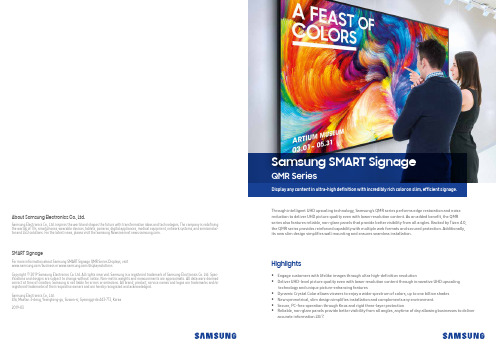
• Engage customers with lifelike images through ultra high-definition resolution• Deliver UHD-level picture quality even with lower resolution content through innovative UHD upscalingtechnology and unique picture-enhancing features• Dynamic Crystal Color allows viewers to enjoy a wider spectrum of colors, up to one billion shades • New symmetrical, slim design simplifies installation and complements any environment. • Secure, PC-free operation through Knox and rigid three-layer protection• Reliable, non-glare panels provide better visibility from all angles, anytime of day allowing businesses to deliver accurate information 24/7.HighlightsThrough intelligent UHD upscaling technology, Samsung’s QMR series performs edge restoration and noise reduction to deliver UHD picture quality even with lower resolution content. As an added benefit, the QMR series also features reliable, non-glare panels that provide better visibility from all angles. Backed by Tizen 4.0, the QMR series provides reinforced capability with multiple web formats and secured protection. Additionally, its new slim design simplifies wall mounting and ensures seamless installation.About Samsung Electronics Co., Ltd.Samsung Electronics Co., Ltd. inspires the world and shapes the future with transformative ideas and technologies. The company is redefining the worlds of TVs, smartphones, wearable devices, tablets, cameras, digital appliances, medical equipment, network systems, and semiconduc-tor and LED solutions. For the latest news, please visit the Samsung Newsroom at .For more information about Samsung SMART Signage QMR Series Displays, visit /business or /displaysolutionsCopyright © 2019 Samsung Electronics Co. Ltd. All rights reserved. Samsung is a registered trademark of Samsung Electronics Co. Ltd. Spec -ifications and designs are subject to change without notice. Non-metric weights and measurements are approximate. All data were deemed correct at time of creation. Samsung is not liable for errors or omissions. All brand, product, service names and logos are trademarks and/or registered trademarks of their respective owners and are hereby recognized and acknowledged.Samsung Electronics Co., Ltd.416, Maetan 3-dong, Yeongtong-gu, Suwon-si, Gyeonggi-do 443-772, Korea 2019-03SMART SignageDisplay any content in ultra-high definition with incredibly rich color on slim, efficient signage.Samsung SMART SignageQMR SeriesSamsung’s superior visual display technology has positioned them as the industry leader in the digital signage market for a decade and in the TV market for 12 years. As an expert in picture quality in the display industry, Samsung is able to deliver best-in-class picture quality through their new QMR series. The signage provides rich and flawless colors, sleek and durable design, powerful performance through Tizen 4.0 and secured protection. Its reliable, non-glare panels provide better visibility from all angles, allowing businesses to deliver important information 24/7. Samsung’s QMR series is also able to upscale even the lowest resolution content to UHD picture quality. For commercial displays, this technology advancement means highly visible signage with unmatched accuracy to help capture the attention of potential customers. It also means savings both in cost and time for businesses who can produce content more inexpensively at a lower resolution and still display it in stunning UHD quality.Key features3Samsung’s new QMR series is able to capture customer attention by providing an incredibly clear picture, showcasing lifelike images and intricate details better than ever before thanks to ultra high-defini -tion 4K resolution.Incredible 4K picture qualityWhen clear visibility is essential, the QMR series incorporates key fea-tures including up to 500 nit brightness and reliable, non-glare pan -els that provide better visibility from all angles, anytime of day. The display is ideal for locations such as airports and commuter stations where 24/7 access to clear and accurate information is crucial.Perfect view with non-glare display2With visual display technology improving across devices, viewers have developed an ever-growing expectation for better pic-ture quality. Additionally, the market has been flooded with a wide variety of color techologies and it’s becoming increasingly important for businesses to have rich and vivid display capabilities. As UHD resolution continues to grow in popularity, it is es -sential for businesses to deliver superb picture quality for their customers. Low quality displays and signage can create negative perceptions of a business. While much content is still being produced at a lower resolution, through Intelligent UHD upscaling technology, Samsung’s QMR series is able to upscale even the lowest resolution content to UHD picture quality.Industry trendWhy Samsung’s QMR series?Intelligent UHD upscaling Dynamic Crystal Color Slim & Flat backdesignTIZEN 4.0Conventional Glare PanelNon-Glare PanelUHD resolution is must-have feature in the future UHD sales forecasted to exceed FHD in 2019UHD(Kunit)FHD(Kunit)UHD(M$)FHD(M$)* Source : IHS ‘18.2Q Final+Forecast($)]* Source : IHS ‘18.2Q Final+Forecast* Note : S tandalone digital signage onlyConsumer TVs, along with Commercial Lite and Hospitality TVs used for signage are excluded.solution based on Samsung’s proprietary intelligent UHD engine that allows content developed at a lower resolution to be elevated to UHD-lev-el quality. It also performs edge restoration and noise reduction to optimize on-screen text and imagery with crisp edges and fine detail.Conventional ConventionalConventionalQMR Series QMR SeriesQMR SeriesDynamic Crystal Color is what brings the incredible, lifelike color to Samsung displays. Using 10-bit processing, the displays are able to show -case a wider spectrum of colors — up to a billion different shades — capturing subtle differences for flawless color expression, critical to businesses in ensuring brand consistency across communication channels. The QMR series also features HDR10+ functionality that converts standard definition (SDR) content to HDR quality for sharper contrast and more vivid colors.Amplified colorsReduced colorsensure accuate RGBexpressionaffect RGB clarityFHD panel UHD panel 2M pixels 8M pixelsIntelligent UHD engine Noise Reduction Edge RestorationUHD1 Billion ColorSlim & Symmetric Design50mm50mm Specif i cationsKey features54Narrow BezelIn a corporate or retail environment, the back of a display is often vis -ible to customers. With the QMR series’ new cable guide feature re -tailers can tuck messy cables away from view. This allows for a clean and more visually-appealing customer shopping experience.Clean cable managementThe all-new slim and symmetrical design of the QMR series signifi -cantly simplifies wall mounting the display and ensures installation is a seamless process. The display’s power inlet direction has been re -designed to sit flush against the wall. The new design sets guarantees a long life cycle ensuring the QMR series will stand the test of time.Slim and symmetrical designThe Samsung SMART Signage Platform (SSSP) is an open-source, all-in-one solution embedded in Samsung SMART signage that sim -plifies installation and maintenance. With SSSP , there is no need for any external devices to communicate with the server or play digital media enjoying easy development, reinforced capability with multi-ple web formats, and secured protection.Powerful, all-in-one solutionThe QMR series features a nearly endless range of business use-cas-es thanks to built-in Wi-Fi and Bluetooth. Wireless connectivity al -lows for personalized and interactive services including enabling integration with beacon technology in store, while also simplifying how businesses showcase content.Wi-Fi and Bluetooth built-inSymmetricSlim DepthLong Life CycleNarrow BezelEasy Development Reinforced Compatibility High Expandability Secured ProtectionSide power inlet for no depth extension* Image is for illustrative purposes only, specific application or program may have to be developed for the depicted usage scenario.。
博思安全产品:解决方案6000标准图形密码门禁说明书

uLarge graphical display with LED backlight, with real time clock and temperature displayuUp to 4 lines of 20 characters and icons, with dedicated On, OFF and PART keysuAlphanumeric text prompting / programming with custom installer static display screen u Adjustable volume, backlight and contrast uTerminal block connectionsThe Solution 6000 Graphic Code Pads have beenthoughtfully designed to provide everything you would expect a top-of-the-line security code pad and much more. The Code Pad is supplied in either a black or white plastic housing which is complimented by an electric blue LED backlighting of the keys and display.The striking appearance will compliment most modern interior designs while also offering advantage in dirty industrial installations. As with all code pads in the range they can be used with or without the hinged door to meet customer taste or requirements.Illuminated rubber keys allow for easy identification and operation in ambient light conditions and provide a positive feel to the user.Red and Green indicators are provided to easilyidentify the Armed and Disarmed modes of operation from a distance and the in-built sounder provides audible feedback via polyphonic-like signalling tones during system operation. The sounder volume is programmable and it also emits a sire sound during alarm conditions.FunctionsLarge back-lit graphical LCD displayOne of the most comprehensive displays available, the large back lit LCD display incorporates the latest pixel technology which graphically identifies all system conditions at a glance. Variable font sizes are used depending on the situation with important information being displayed in a large bold font, while up to 4 lines of text can be displayed when more information is required.At all times the user is prompted in alphanumeric text clearly identifying the current operating mode,enhancing feedback for trouble-free and simple operation.All system programmable features and options are displayed in full text on the code pad, allowing the system to be programmed and configured without referring to the manual.Adjustable contrast and backlightingDisplay screens can also be customised to show the installer logo or contact information when the system is in idle mode. Brightness and contrast levels areprogrammable via the code pad so the user can adjust the display to their desired optimum clarity.The entire display and key area is constantlyilluminated with a subtle glow. During operation thecode pad automatically switches to a brighter modefor easy use. The user may elect to fully extinguish thecode pad when not in user.Technical specificationsPower RequirementsEnclosureEnvironmental ConsiderationsOrdering informationCP700B Solution 6000 Graphic Keypad - WhiteOrder number CP700BCP710B Solution 6000 Graphic Keypad - BlackOrder number CC710B2Represented by:Americas:Europe, Middle East, Africa:Asia-Pacific:China:America Latina:Bosch Security Systems, Inc. 130 Perinton Parkway Fairport, New York, 14450, USA Phone: +1 800 289 0096 Fax: +1 585 223 9180***********************.com Bosch Security Systems B.V.P.O. Box 800025617 BA Eindhoven, The NetherlandsPhone: + 31 40 2577 284Fax: +31 40 2577 330******************************Robert Bosch (SEA) Pte Ltd, SecuritySystems11 Bishan Street 21Singapore 573943Phone: +65 6571 2808Fax: +65 6571 2699*****************************Bosch (Shanghai) Security Systems Ltd.201 Building, No. 333 Fuquan RoadNorth IBPChangning District, Shanghai200335 ChinaPhone +86 21 22181111Fax: +86 21 22182398Robert Bosch Ltda Security Systems DivisionVia Anhanguera, Km 98CEP 13065-900Campinas, Sao Paulo, BrazilPhone: +55 19 2103 2860Fax: +55 19 2103 2862*****************************© Bosch Security Systems 2014 | Data subject to change without notice 9771793419 | en, V3, 27. Oct 2014。
【诺瓦科技】智慧城市LED灯杆屏多媒体播放器快速使用指南英文版

Taurus SeriesMultimedia PlayersQuick S tart Guide Document V ersion:V1.3.2Document Number:NS120100369Copyright © 2018 Xi ’an NovaStar Tech Co., Ltd. All Rights Reserved.No part of this document may be copied, reproduced, extracted or transmitted in any form or by any means without the prior written consent of Xi ’an NovaStar Tech Co., Ltd.Trademarkis a trademark of Xi ’an NovaStar Tech Co., Ltd.Statementwww.novastar.techi aurus Series Multimedia Players Quick Start GuideTable of ContentsTable of ContentsTable of Contents ............................................................................................................................ ii 1 Overview .. (1)1.1 Scenario (1)1.2 Procedures .................................................................................................................................................. 1 You are welcome to use the product of Xi ’an NovaStar Tech Co., Ltd. (hereinafter referred to as NovaStar). This document is intended to help you understand and use the product. For accuracy and reliability, NovaStar may make improvements and/or changes to this document at any time and without notice. If you experience any problems in use or have any suggestions, please contact us via contact info given in document. We will do our best to solve any issues, as well as evaluate and implement any suggestions.T2Preparation ....................................................... (2)2.1 Getting and Installing Software (2)2.2 Getting Required Account Information (3)3 Taurus Connections (4)3.1 Connecting via Ethernet Cable (4)3.2 Connecting via Local Area Network (LAN) (4)3.3 Connecting via Wi-Fi (5)3.3.1 Wi-Fi AP Mode ..........................................................................................................................................53.3.2 Wi-Fi Sta Mode (6)3.3.3 Wi-Fi AP+Sta Mode (6)4 Receiving Card Parameter Configuration (8)4.1 Loading Configuration File or Configuring the Parameters Manually Through NovaLCT (8)4.2 Loading the Configuration File Through ViPlex Handy (9)5 Screen Configuration (10)6 General Operations (11)6.1 Taurus Login with ViPlex Handy (Android and iOS) (11)6.2 Taurus Login with ViPlex Express (Windows) (11)7 Caution (13)www.novastar.tech ii1Overview1.1 Scenario 1.2 Procedureswww.novastar.tech2 Preparation2 PreparationThis document introduces a quick way to use Taurus series multimedia players and provides instructions for the first-timer.www.novastar.tech2 Preparation3 Taurus ConnectionsTaurus Series Multimedia PlayersQuick Start Guide3 Taurus Connections 3.1 Connecting via Ethernet Cablewww.novastar.tech 3Taurus Series Multimedia PlayersQuick Start GuideNetwork DiagramConfiguration Users can access the Taurus directly when it is connected via the Ethernet cable.ViPlex Handy:Step 1 Refer to 6.1 Taurus Login with ViPlex Handy (Android and iOS ) to log in to the Taurus.Step 2 Click the screen name to enter the Screen management page.Step 3 Choose Network Settings > W ired Network Setting .Step 4 Turn off DHCP and set static IP address for the Taurus.ViPlex Express:Step 1 Refer to 6.2 Taurus Login with ViPlex Express (Windows ) to log in to the Taurus.Step 2 At the top right, click and select DHCP Service .Taurus Series Multimedia PlayersQuick Start GuideStep 3 Enable DHCP service to automatically assign an IP address to the Taurus.3.2 Connecting via Local Area Network (LAN)Network DiagramUsers can access the Taurus through LAN when it is connected via LAN. www.novastar.techTaurus Series Multimedia PlayersQuick Start Guide 3 Taurus ConnectionsConfigurationNo need for configuration.3.3 Connecting via Wi-FiThe Taurus series products have dual Wi-Fi function which can provide Wi-Fi hotspotas well as serve as Wi-Fi Station at the same time. The Wi-Fi working frequencyrange is 2400 MHz to 2483.5MHz.Users can access the Taurus directly when it is connected via Wi-Fi AP .3.3.1 Wi-Fi AP ModeNetwork DiagramConfigurationNo need for configuration. Please connect the Wi-Fi AP of the Taurus. SSID is “AP +last 8 digits of the SN”, for example, “AP10000033”. The default password is“12345678”.3.3.2 Wi-Fi Sta ModeNetwork DiagramUsers can access Taurus through external router when it is connected via Wi-Fi Sta.ConfigurationStep 1Refer to 6 General Operations to log in to the Taurus. Step 2Turn on Wi-Fi Sta mode. Click the Wi-Fi name of the external router and then enter the password of the Wi-Fi.● ViPlex Handy: Select N etwork Settings > W i-Fi Setting in the S creenmanagement page.●ViPlex Express: Select S creen Control > N etwork configuration .3.3.3 Wi-Fi AP+Sta ModeBy using Wi-Fi AP+Sta connection, users can directly access the Taurus or access the Internet through bridging connection.Network Diagram ConfigurationStep 1 Refer to 6 General Operations to log in to the Taurus.Step 2 Turn on Wi-Fi Sta mode. Click the Wi-Fi name of the external router and then enterthe password of the Wi-Fi.● ViPlex Handy: Select Network Settings > Wi-Fi Setting in the Screen management page.●ViPlex Express: Select Screen Control > Network configuration .Related Information● ●The Taurus can be connected to the Internet through following two ways. The priority order of the two ways is from high to low.Wired network Wi-Fi StaQuick Start GuideReceiving Card Parameter ConfigurationStep 5 ClickStep 6 Confirm whether the local PC has the required receiving card configuration file.www.novastar.tech4 Receiving Card Parameter Configuration● Yes. Please perform Load Configuration File .● No. Please perform Manual Configuration .Loading Configuration File Step 1 Select Load Configuration File . Click Browse to choose a configuration file from the local PC.Step 2 Click Next to load the configuration file.Manual ConfigurationStep 1 Select Configure Screen and click Next . Step 2 Configure receiving card parameters based on actual conditions. Step 3 Click Send to Receiving Card .Step 4 Adjust parameters until the screen displays normally and then click Save . Step 5 (Optional) Click Save System Configuration File to back up the receiving card configuration file to the local PC.4If receiving card parameters are already configured, please skip this chapter and perform the operations in 5 Screen Configuration . Loading Configuration File or Configuring the 4.1 Parameters Manually Through NovaLCTStep 1 Open NovaLCT and choose User > M edia Player Login . The system automatically searches the multimedia players in the same networksegment and then displays them in a specified sorting order. Step 2Click the terminal name in the terminal list. Step 3Click Connect System . Step 4Enter user name and password for logging in the terminal, and click OK . The default user name is “ a dmin ” , and the default password is “ 123456 ”. on the main interface, and the Screen Configuration windowpops up as shown in Figure 4-1 .Figure 4-1 The Screen Configuration windowTaurus Series Multimedia PlayersQuick Start Guide4.2 Loading the Configuration File Through ViPlex HandyStep 1 Save the receiving card configuration file to mobile phone.Step 2 Refer to 6.1 Taurus Login with ViPlex Handy (Android and iOS) to log in to the Taurus.Step 3 Click screen name to enter the Screen management page.Step 4 Select Screen Settings > RV Card Configuration to enter the RV CardConfiguration page.Step 5 Select the receiving card configuration file and click Send.5 Screen Configuration5 Screen ConfigurationStep 1 Refer to 6.1 Taurus Login with ViPlex Handy (Android and iOS) to log in to the Taurus.Step 2 Click screen name to enter the Screen management page.Step 3 Select Screen Configuration to enter the Screen Configuration page.Step 4 Configure screen information based on actual conditions and click OK.www.novastar.tech6 General Operations6 General OperationsTaurus series products feature the Wi-Fi AP function which is taken as the example bythis chapter to introduce T aurus Login methods.6.1 Taurus Login with ViPlex Handy (Android and iOS)Before You Begin●Acquire the SSID and password of Wi-Fi AP of Taurus series products. SSID isdefault to be composed of AP and the last 8 numbers of SN, and thepassword is default as “12345678”.●Acquire the login password of user “admin” of which the default password is“123456”.Operating ProceduresViPlex Handy can connect numerous Taurus series products.Step 1 Connect Wi-Fi AP of the Taurus series products.Step 2 Start ViPlex Handy.System can automatically detect the Taurus series products and refresh Screen list.Users can also slide down Screen list to manually refresh the list.●: denotes that Taurus is online and you can log into it.●: denotes that Taurus is offline and you cannot log into it.●: denotes that Taurus login is successful.Step 3 Click Connect next to the screen name.Step 4 Enter the user name and password and click Login.6.2 Taurus Login with ViPlex Express (Windows)Before You Begin●Acquire the SSID and password of Wi-Fi AP of Taurus series products. SSID is default to be composed of AP and the last 8 numbers of SN, and the password is default as “12345678”.www.novastar.tech6 General Operations●Acquire the login password of user “admin ” of which the default password is “123456”.Operating ProceduresViPlex Express can connect numerous Taurus series products.Step 1 Connect Wi-Fi AP of the Taurus series products. Step 2 Start the ViPlex Express.Step 3 Click Refresh and the screen list will be displayed on the page.● ● ●: denotes that Taurus is online and you can log into it. : denotes that Taurus is offline and you cannot log into it. : denotes that Taurus login is successful.After the Taurus is found by ViPlex Express, the ViPlex express will try to log into to the Taurus with the default account or the account used for last login.Step 4 Taurus login is successful or not.Yes. appears and no further operation is required. No.appears and then perform Step 5 .Step 5Click Connect o n the right of the screen information. Step 6Enter the username and password, and click OK .●www.novastar.tech7 Caution 7 CautionFCC CautionAny changes or modifications not expressly approved by the party responsible forcompliance could void the user's authority to operate the equipment.This device complies with part 15 of the FCC Rules. Operation is subject to thefollowing two conditions: (1) This device may not cause harmful interference, and (2)this device must accept any interference received, including interference that maycause undesired operation.Note: This equipment has been tested and found to comply with the limits for a ClassA digital device, pursuant to part 15 of the FCC Rules. These limits are designed toprovide reasonable protection against harmful interference when the equipment isoperated in a commercial environment. This equipment generates, uses, and canradiate radio frequency energy and, if not installed and used in accordance with theinstruction manual, may cause harmful interference to radio communications.Operation of this equipment in a residential area is likely to cause harmful interferencein which case the user will be required to correct the interference at his own expense.This equipment complies with FCC radiation exposure limits set forth for anuncontrolled environment .This equipment should be installed and operated withminimum distance 20cm between the radiator & your body.This transmitter must not be co-located or operating in conjunction with any otherantenna or transmitter.CE CautionThis equipment should be installed and operated with minimum distance 20cmbetween the radiator & your body.IC WarningRSS-Gen Issue 3 December 2010"&"CNR-Gen 3e éditionDécembre 2010:- English:This device complies with Industry Canada licence-exempt RSS standard(s).Operation is subject to the following two conditions: (1) This device may not causeinterference, and (2) This device must accept any interference, including interferencethat may cause undesired operation of the device.- French:www.novastar.tech7 CautionLe présentappareilestconforme aux CNR d'Industrie Canada applicables auxappareils radio exempts de licence. L'exploitationestautorisée aux deux conditionssuivantes:(1) l'appareil ne doit pas produire de brouillage, et(2) l'utilisateur de l'appareildoit accepter tout brouillageradioélectriquesubi, mêmesi lebrouillageest susceptible d'encompromettre le fonctionnement.Replaceable BatteriesCAUTION: Risk of Explosion if Battery is replaced by an Incorrect Type. Dispose ofUsed Batteries According to the Instructions.Batteries RemplaçablesATTENTION: Risque d'explosion si la Batterie est remplacée par un Type Incorrect.Jeter les Batteries Usées Conformément aux Instructions.。
萨福铝焊机说明书

B - 安装调试 ............................................................................................................10 1. 拆除包装 .......................................................................................................10 2. 送丝机连接...................................................................................................10 3. 主电源的电路连接 .....................................................................................10 4. 焊枪的连接...................................................................................................10
中文
目录
安全说明 .....................................................................................................................2
A - 总体介绍 ...............................................................................................................7 1. 装置简介 .........................................................................................................7 2. 焊接设备组成 ................................................................................................7 3. 前面板描述.....................................................................................................8 4. 选配件..............................................................................................................8 5. OPTIPULS i / i W技术规格 .............................................................................8 6. 尺寸和重量.....................................................................................................9 7. 冷却装置的技术规格......................................................................................9
- 1、下载文档前请自行甄别文档内容的完整性,平台不提供额外的编辑、内容补充、找答案等附加服务。
- 2、"仅部分预览"的文档,不可在线预览部分如存在完整性等问题,可反馈申请退款(可完整预览的文档不适用该条件!)。
- 3、如文档侵犯您的权益,请联系客服反馈,我们会尽快为您处理(人工客服工作时间:9:00-18:30)。
SIMATIC HMI ConfiguringText-based Displays Product BriefEdition 12/01A5E00148094Safety GuidelinesThis manual contains notices which you should observe to ensure yourown personal safety, as well as to protect the product and connectedequipment. These notices are marked as follows according to the levelof danger:Dangerindicates an imminently hazardous situation which, if not avoided, willresult in death or serious injury.Warningindicates a potentially hazardous situation which, if not avoided, couldresult in death or serious injury.Cautionused with the safety alert symbol indicates a potentially hazardoussituation which, if not avoided, may result in minor or moderate injury.Cautionused without safety alert symbol indicates a potentially hazardoussituation which, if not avoided, may result in property damage.Attentionindicates that unwanted events or status can occur if the relevantinformation is not observed.Notedraws your attention to particularly important information on the product,handling the product, or to a particular part of the documentation.Qualified PersonnelEquipment may be commissioned and operated only by qualifiedpersonnel. Qualified personnel within the meaning of the safety noticesin this manual are persons who are authorized to commission, groundand identify equipment, systems and circuits in accordance with safetyengeneering standards.Correct UsageNote the following:WarningThe equipment may be used only for the applications stipulated in thecatalog and in the technical description and only in conjunction withother equipment and components recommended or approved bySiemens.Startup must not take place until it is established that the machine,which is to accommodate this component, is in conformity with theguideline 98/37 ECC.Faultless and safe operation of the product presupposes propertransportation, proper storage, erection and installation as well ascareful operation and maintenance.TrademarksThe registered trademarks of the Siemens AG can be found in thepreface. The remaining trademarks in this publication may betrademarks, whose use by third parties for their own purposes couldviolate the rights of the owner.ImpressumEditor and Publisher: A&D PT1 D1Copyright Siemens AG 2001 All rights reserved Exclusion of liabilityThe transmission and reproduction of this documentation and the exploitation and communication of its contents are not allowed, unless expressly granted. Violators are liable for damages. All rights reserved, especially in the case of the granting of a patent or registration by GM.We have checked the content of this publication for compliance with the described hard and software. However, discrepancies cannot be excluded, with the result that we assume no guarantee for total compliance. The information in this publication is checked regularly, and any necessary corrections are included in the following editions. We would be grateful for any suggestions for improvement.Siemens AGBereich Automation & DrivesGeschäftsgebiet SIMATIC HMI Postfach 4848, D-90327 Nuernberg ã Siemens AG 2001Technical data subject to change.Siemens Aktiengesellschaft Order number A5E00148094Configuring Text-based Displays Contents ContentsPageIntroduction (3)Commissioning Operating Units (6)Basic Steps for a Configuration (8)Extend Configuration with Simple Elements (16)SIMATICâ is a registered trademark of Siemens AG.The other designations in this document may be trademarks which, whenused by others for their own purposes, may constitute a violation of theowners’ rights.Siemens AG12Siemens AGConfiguring Text-based Displays Introduction Siemens AG 3IntroductionProTool is the configuration software for operating unitsrequired to visualize and operate processes. Operating unitsare basically divided into three families:• Units with a text-based display (e.g. TD 17, OP 3, OP 7,OP 17)• Units with a graphics display (e.g. OP 27, OP 37, TP 27,TP 37)• Windows-based systems (e.g. Panel PC, standard PC,MP 370, MP 270, MP 270B, OP 270)ProTool is available in three versions:• ProTool/Pro to configure the entire unit family• ProTool to configure units with graphics and text-based displays• ProTool/Lite to configure units with text-based displaysThe procedures and descriptions in this quick referencemanual should help provide an introduction to configuring unitswith text-based displays. PLC-specific details for creating theassociated program are not provided.Notes on using the quick reference manualTexts or inputs required for the configuration which can beselected from items provided appear in Courier typeface.Menus, menu options, dialogs or texts in dialog boxes whichcan be selected appear in italics .Introduction Configuring Text-based Displays Further informationFurther information is provided in the following:• Online help•ProTool User's Guide - Configuring Text-based Displays•User's Guide - CommunicationsElements of a configurationThe following elements, described below, are available to carryout a configuration and are explained by means ofconfiguration examples in this manual.Creating screensScreens enable processes to be visualized. Screens indicatethe current process statuses in the form of numeric values andalso provide function keys with which to modify values and,thus, influence processes.Linking screensThe screens involved in a configuration can be linked to eachother.PLC process value input/outputProcess values can be displayed and modified directly by usinginput and output fields. The entries can be assigned limitvalues and protected by a password. Output is possible in anumber of display formats, such as decimal or binary.Integrating textsInput/output fields and function keys can be labeled with textfor the user.4Siemens AGConfiguring Text-based Displays IntroductionSiemens AG 5Display messagesMessages indicate events and statuses in the process.ProTool distinguishes between event messages and alarmmessages. Event messages relate to the status of a machineor process. Alarm messages indicate operating faultsconcerning a machine or process and must be acknowledged.The TD17 supports the above named elements by displayingin event messages and issuing process values in messages.Commissioning Operating Units Configuring Text-based Displays 6Siemens AG Commissioning Operating UnitsHardware structureThe following figure illustrates an example of a variant of thehardware structure using the OP17:A Serial connection for downloading configurations(configuration phase only)B Connection between operating unit and PLC(configuration phase and online operation)Installing the softwareInstalling ProTool on a PC− Insert the installation CD in the CD-ROM drive; setup starts automatically after a few seconds− Follow the instructions on the screenConfiguring Text-based Displays Commissioning Operating Units Siemens AG 7Using online help and context-sensitive helpIf problems arise during the configuration, or furtherinformation concerning specific points is required, proceed asfollows:− Click on the question mark symbol− Click on the elements for which information is requiredUsing context menusContext menus are available for the elements of aconfiguration. Context menus can be used to trigger actionswhich are related to the corresponding element. Proceed asfollows to call in a context menu:− Select an element−Click the right mouse buttonBasic Steps for a Configuration Configuring Text-based Displays 8Siemens AG Basic Steps for a ConfigurationStart ProTool− Double click on the ProTool symbol on the desktopDefine the new configurationIn the case of new ProTool users, it is recommended to usestandard configurations as a basis for individual configurations.Standard configurations are available for all operator panelswith a text-based display. They contain screens in whichgenerally used functions are already configured.− Select File → New− Select the operating unit to be configured− Click on Continue− Select PLC− Set further parameters for the PLC under ParameterExample: Parameters when an S7 is connectedConfiguring Text-based Displays Basic Steps for a ConfigurationSiemens AG 9− Click on Continue− Activate checkbox Use Standard Project− Click on Continue− Enter a name for the configuration in Project− Click on FinishDefine default settingsIn order for the operating unit to perform special tasks,communication areas must be configured in the PLC.Communication areas are necessary, for example, to triggerand acknowledge messages. Both operating unit and PLCaccess the same configured data areas in order tocommunicate with each other.Proceed as follows to configure a communication area foralarm messages:− Select System → Area Pointers− Select Type Alarm Messages− Click on Add− In PLC , select the PLC used in the system− Define the other settings for alarm messages− Click on OKSetup this data area in the PLC program too.In the case of connection to a SIMATIC S5, a communicationarea of the type Interface Area must always be set up forcommunication between the operating unit and PLC. Thesetup procedure is the same as for setting up a communicationarea for alarm messages described above.Basic Steps for a Configuration Configuring Text-based Displays 10Siemens AG Creating the start screen for the configurationThe start screen is the first screen displayed with regard to aconfiguration. The start screen identification has the followingeffect:• OP7, OP17:the start screen is displayed immediately after the unit hasbooted• Other units:the unit is in message level after booting; press the ENTERkey to call the start screenAdd new screen to a configurationProceed as follows:− Double click on Screens in the project windowA new screen is added and opened.Configuring Text-based Displays Basic Steps for a ConfigurationSiemens AG 11Identify new screen as start screenProceed as follows:− Click on the screen entry on the right-hand side of the project window using the right mouse button− Select Properties in the context menu− Activate checkbox Start Screen− Click onOK Add descriptive text to start screenIn the case of units with text-based displays, each screen iscomprised of several screen entries.Proceed as follows:− Click on the required line in the first screen entry of the start screen− Enter the text Start ScreenBasic Steps for a Configuration Configuring Text-based Displays 12Siemens AG Enable switch to download modeBefore a generated configuration can be downloaded from aPC to an operating unit, the operating unit must be set toDownload mode. In order to access Download mode simplyand quickly, assign the function Mode to a function key.The function should be assigned to a global function key sothat Download mode can be activated from any screen in theconfiguration. When a global function key is assigned, thefunction is available in every screen.When using operating unit OP3, the function must be assignedto a local function key since no global assignment is possible.Where a local function key is assigned, the function is onlyavailable a certain screen.Configuring Text-based Displays Basic Steps for a ConfigurationSiemens AG 13Assign function Mode globallyProceed as follows:− Select System → Screen/Keys− Click on the required function key− Open the folder Toggle in Select Object− Assign the function Mode by double clicking on the functionkey− Enter 2 in parameter Mode 2− Click on OKtwiceBasic Steps for a Configuration Configuring Text-based Displays 14Siemens AG Activate configuration on operating unitCompile operation-capable configurationProceed as follows:− Click on the symbol for compiling− Follow the instructions on the screenDownload operation-capable configuration to operating unitThe configuration must be downloaded to the operating unit fortesting. Downloading is carried out via a direct serialconnection between the PC and operating unit.Proceed as follows:− Select File → Settings → Download−Set downloading parameters− Click on OKIn order to download the configuration, the operating unit mustbe in Download mode. The procedure with which to activateDownload mode depends on the configuration status of theoperating unit:• An operating unit which has not received a configuration switches to Download mode automatically.• An operating unit which contains a configuration can be switched to Download mode directly after switching on thepower supply by pressing the key combination:ESC , CURSOR RIGHT and CURSOR DOWN .The key combination deletes the configuration.Configuring Text-based Displays Basic Steps for a ConfigurationSiemens AG 15• If a function key has already been assigned for switchingthe unit to Download mode, as described in Section Enableswitch to download mode on Page 12, simply press thatkeyWhen the message Ready for transfer appears on theoperating unit, proceed as follows:− Click the download symbolAfter downloading has been completed successfully, theoperating unit is rebooted with the downloaded configuration. Itcan then be tested.Extend Configuration with Simple Elements Configuring Text-based Displays 16Siemens AG Extend Configuration with Simple ElementsA condition for the procedures described in this section is thatthe following configuration steps, defined in the Section BasicSteps for a Configuration, have been carried out:• Define the new configuration (Page 8)• Define default settings (Page 9)• Creating the start screen for the configuration (Page 10)• Enable switch to download mode (Page 12)Add second screen to configuration and configure changing screensAt this point, the configuration only contains the start screen. Ifother screens are to be added, the operator must be able toswitch between the screens.This example illustrates how a second screen is linked to thestart screen. A function key is assigned which enablesswitching to a different screen from any screen.Configuring Text-based Displays Extend Configuration with Simple ElementsSiemens AG 17Add second screen to configurationProceed as follows:− Double click on Screens in the project windowA new screen is added and opened.Add descriptive text to second screenProceed as follows:− Click on the required line in the first screen entry of the second screen− Enter text Second screenConfigure switching to second screenProceed as follows:− Click required function key in the first screen entry of the start screen− Open the folder Screens in Select Object− Double click on Select Screen− Select the name of the second screen under Screen Name− Click onOKExtend Configuration with Simple Elements Configuring Text-based Displays18Siemens AG Configure change to start screenProceed as follows:− Click on the required function key in the first screen entry of the second screen− Open the folder Screens in Select Object− Double click on Select Screen− Select the name of the start screen in Screen Name− Click on OK twiceThe sequence of screens displayed is stored in the operatingunit. Return to the screen previously displayed by pressing theESC key.The configuration can be tested at this point. The procedure isdescribed in Section Activate configuration on operatinguniton Page 14.Configuring Text-based Displays Extend Configuration with Simple Elements Siemens AG 19Input/output of PLC process values as numeric valuesThis example illustrates how a PLC process value is entered inan operating unit input field and output via an output field.Inserting an input fieldProceed as follows:− Click on the first line of the second screen entry of the start screen− Click on the Input/Output Field symbol− Select Field Type InputGenerate a new tagProceed as follows:− Click on the context menu symbol− Click on Newin the context menuExtend Configuration with Simple Elements Configuring Text-based Displays20Siemens AG − Define tag parameters− Click OK twiceExample: Tag for S7 connectionA Formatting for display in the configurationB Address in the PLCThe representation of the address in the PLC is dependent onthe PLC selected. ProTool adapts dynamically to theprogrammable address area.Configuring Text-based Displays Extend Configuration with Simple ElementsSiemens AG 21Insert an output fieldProceed as follows:− Click on the second line in the second screen entry of the start screen− Click on the Input/Output Field symbol− Select Field Type Output− Select the name of the tag generated in Tag− Click onOKExtend Configuration with Simple Elements Configuring Text-based Displays22Siemens AG Set up a data area for the tag in the PLC. Using the input field,it is possible to enter a process value in the PLC which is thenissued via the output field.The configuration can be tested at this point. The procedure isdescribed in Section Activate configuration on operatinguniton Page 14.Configuring Text-based Displays Extend Configuration with Simple Elements Siemens AG 23Display messagesIn order to issue information concerning current process faultsin the form of messages, a communication area wasconfigured for alarm messages in Section Define defaultsettings on Page 9.Proceed as follows to configure alarm message texts foroutput:− Messages in the project window− Double click on Alarm Messages on the right-hand side ofthe project window− Enter the alarm message text for Alarm Message 1 in line 0001− Enter the alarm message text for Alarm Message 2 in line 0002− Enter the alarm message text for Alarm Message 3 in line 0003The status line, at the bottom right of the screen, indicates therespective address linking the alarm message to the PLC. Thisinformation is PLC-specific.In order to display the configured alarm messages on theoperating unit, the corresponding bits must be set in the PLCusing the PLC program.The configuration can be tested at this point. The procedure isdescribed in Section Activate configuration on operatinguniton Page 14.24Siemens AG。