OMC产品V01B01R01D04SP2特性说明
LTE-OMC产品配置手册(3.20)

4.其他建议:
为了我们能够及时与您联系,请填写有关您本人的以下信息:
姓名:___________________单位:______________________________
电话:___________________地址:______________________________
为了我们能更好地为您服务,请填写您对我们资料的意见,并传真至:010-58832769大唐移动通信设备有限公司客服中心,或通过邮箱support@反馈,我们将对好的建议给予奖励。
1.请您对以下表格中各项进行评价,并将评价结果填写在相应单元。(打“”)
评价
项目
很好
好
一般
差
说明:
说明、提示、窍门、思考:对操作内容的描述进行必要的补充和说明。
注意:
小心、注意、警告、危险:提醒操作中应注意的事项。
目 录
第1章
1.1
LTE-OMC作为TD-LTE系统的操作维护中心,主要完成对LTE系统的网络设备EPC、eNode B以及OMC自身的操作维护,提供包括配置、告警、性能、安全、日志、软件等管理工作。在系统开通过程中能够对网络设备进行数据配置,在系统运行过程中能够监控网络的运行状况和质量,并提供系统软件和数据升级功能。
2.3.3
处理能力计算:
告警:根据测算OMC标准配置下单网元告警30条/秒,多网元告警100条/秒
性能:按照5分钟最小粒度计算,单个网元计数器平均个数为1000个(以小区为参照),OMC标准配置可处理100万计数器/分钟。
存储能力计算:
OMC告警管理数据存储容量计算公式:
根据测算,每条告警信息在数据库中占用2.2KB,平均每个基站每天上报30条告警,每个EPC每天上报50条告警。
OM-CP-QUADRTD 温度计数器产品说明书

OM-CP-QUADRTD
OM-CP-QUADRTD data logger shown smaller than actual size.
U 100Ω Pt RTD Input U Real Time Operation
1
)UHHSKRQH _ ,QWHUQDWLRQDO _ )D[ _ 6DOHV#RPHJDFRXN
ZZZRPHJDFRXN
81,7(' 67$7(6 ZZZRPHJDFRP 7&20(*$
RESISTANCE Nominal Range: 0 to 500Ω Resolution: 0.001Ω Calibrated Accuracy: ±0.03Ω@ 25°C ambient Specified Accuracy Range: 0 to 500Ω Channels: 4 Input Connection: Removable screw terminal; 2, 3, or 4 wire interface Start Time: Start time and date are programmable through software Real Time Recording: Device may be used with PC to monitor and record data in real time Memory: 21,845 readings per channel Recording Interval: 2 sec to 12 hours, selectable through software Calibration Date: Automatically recorded within device to alert user when calibration is required Temperature Calibration: Digital calibration is available in software Power: 9V lithium battery (included); 120 Vac power optional
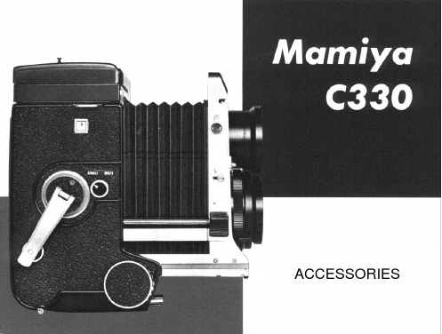
姆米亚C系列摄像机配件说明书
conventional single exposure attachment for the MAMlYA C series cannot be utilized on this camera.
Magnification of this finder is approximately 2.5 times the image on the ground glass focusing screen, particularly bright and clear.
CdS Porrofinder
This is a Porrofinder with built-in CdS exposure meter Match the index needles within the finder by turning the dial on the back of the f i n d e r , a n d r e a d t h e dial scale. This device measures the amount of light traveling through the viewing lens offering corrrect exposure setting even for amateurs.
for the Mamiya Press and Mamiya RB.
24
H Accessories
Single Exposure Attachment
By using the single exposure attachment provided, single exposures can be made of dry plates (2 1/2 x 3 1/2 in., 6.5x9cm) or cut films (4 3/4 x 6 1/2 in. cut film divided into four 1/4 sizes or 2 1/2 x 3 1/2 in.) When using 4 3/4 x 6 1/2 in. cut film divided into four one-quarter sizes, use a J-type film sheath. When using 2 1/2 x 3 1/2 in. film, use a D-type film sheath.
奥美晨曦系列微波传感器说明书

OS100 SERIES Mini-Infrared Transmitter e-mail:**************For latest product manuals: Shop online at User’s G ui d e***********************Servicing North America:U.S.A. Omega Engineering, Inc.Headquarters: Toll-Free: 1-800-826-6342 (USA & Canada only)Customer Service: 1-800-622-2378 (USA & Canada only)Engineering Service: 1-800-872-9436 (USA & Canada only)Tel: (203) 359-1660 Fax: (203) 359-7700e-mail:**************For Other Locations Visit /worldwideThe information contained in this document is believed to be correct, but OMEGA accepts no liability for any errors it contains, and reserves the right to alter specifications without notice.Table of ContentsSection ...................................................................PageSafety Warnings and IEC Symbols (iii)Caution and Safety Information (iii)Section 1 Introduction ....................................................................1-1Section 2Installation ......................................................................1-12.1 Unpacking and Inspection ......................................1-12.2 Electrical Connection ..............................................2-1Section 3Operation ........................................................................3-13.1 Main Board ................................................................3-13.2 Ambient Temperature ..............................................3-23.3 Atmospheric Quality ................................................3-33.4 Measuring Temperature ..........................................3-33.5 Alarm Setting ............................................................3-43.6 Adding Extension Cable...........................................3-4Section 4 Laser Sight Accessory ...................................................4-14.1 Warning and Cautions .............................................4-14.2 Operating the Laser Sight Accessory .....................4-1Section 5 Specifications .................................................................5-15.1 General .......................................................................5-15.2 Laser Sight Accessory (OS100-LS) ..........................5-2Section 6Emissivity Table .............................................................6-1iTable of FiguresFigure Description Page2-1Power Supply & Analog Output Connections ..........2-12-2 Alarm Output Connection ............................................2-13-1 Main PC Board ...............................................................3-23-2 Sensor..............................................................3-2Housing3-3 Optical Field of View .....................................................3-43-4Setting the Temperature Engineering Unit..................3-43-5Mounting Bracket OS100-MB .......................................3-53-6Water Cooling Jacket, OS100-WC ................................3-53-7Typical Water Cool Jacket Assembly ...........................3-53-8Air Purge Collar, OS100-AP..........................................3-63-9DIN Rail Mounting Adapter, OS100-DR ....................3-63-10NEMA-4 Aluminum Enclosure ....................................3-64-1Laser Sighting Accessory, OS100-LS ............................4-24-2Laser Warning Label ......................................................4-2iiSafety Warnings and IEC SymbolsThis device is marked with international safety and hazard symbols in accordance with IEC 1010. It is important to read and follow all precautions and instructions in this manual before operating or commissioning this device as it contains important information relating to safety and EMC. Failure to follow all safety precautions may result in injury and or damage to your calibrator. IEC symbols DescriptionCaution and Safety Information• If the equipment is used in a manner not specified in this manual, the protection provided by the equipment may be impaired.• The installation category is one (1).• There are no user replaceable fuses in this product• The output terminals of this product are for use with equipment (digital meters, chart recorders, etc,) which have no accessible five parts. Such equipment should comply with all the applicable safety requirements.• Do not operate the equipment in flammable or explosive environments.• All connections to the thermometer should be made via a shielded cable, 24 AWG stranded wire with the following ratings: 300V , 105°C (221°F), PVC insulation.• Power must be disconnected before making any electrical connections.• The power supply used to power the thermometer should be VDE or UL approved with the following ratings: 12 to 24vdc @150mA with overload protection of 500mA.iiiCaution, refer to accompanying documentsDirect Current Laser SymbolFrame or ChassisNOTES: ivSection 1 - IntroductionThe low cost OS101 mini-infrared transmitter provides non-contacttemperature measurement for industrial applications. The unit measures atemperature range of -18 to 538°C (0-1000°F) and provides a linear analogoutput of either 4-20 mA, 0-5 VDC, K type TC, 1 mV/°C, or 1 mV/°F.The new OS102 mini-infrared transmitter has all the functions of OS101plus a built-in LED display that shows the measured temperature indegrees F or degrees C which is switchable in the field.The miniature sensor head design 2.5 cm dia. x 6.3 cm Length (1" x 2.5") isideal for measuring temperature in confined, and hard to reach places.The aluminum sensor head as well as the rugged electronic housing (Diecast Aluminum) are NEMA-4 rated.The sensor head is connected to the electronic housing via a 1.82 m (6 feet)shielded cable as standard. The unit provides field adjustable alarmoutput.Section 2 - Installation2.1UnpackingRemove the packing list and verify that you have received all yourequipment. If you have any questions about the shipment, please callCustomer Service at:1-800-622-2378 or 203-359-1660. We can also be reached on the internet:e-mail:**************When you receive the shipment, inspect the container and equipment forany signs of damage. Note any evidence of rough handling in transit.inspection. After examination and removing contents, save packing material and carton in theevent reshipment is necessary.The following items are supplied in the box:• The infrared transmitter including the sensor head and the 1.82 m(6 feet) shielded cable• User's Manual• Mounting Nut1-1The following describes the ordering information:OS102 or OS101 - MA- *,**, where The following optional accessories are available:Here are the Features of OS101 and OS102 infrared transmitters:2.2Electrical Connection Sensor Head Cable - The Sensor head is pre-wired to a 1.8 m (6 feet)shielded cable. Plug & lock-in the male connector to the mating female connector on the aluminum housing.Power & Output Connection - Open the cover of the main aluminum housing. Slide the cable through the strain relief and connect the wires to the terminal block on the board as shown in Fig. 2-1. For Alarm output connection, refer to Fig. 2-2.2-1MA - 4/20 mA output V1 - 0 to 5 VDC output K - Thermocouple output, K type MV - Millivolt output C - 1 mV/°C output F - 1 mV/°F output HT- High temperature sensor head3-1Figure 2-2. Alarm Output Connection Section 3 - Operation3-1Main BoardThe Main Board is shown in Fig. 3-1. Here are the important components on the board:(1) - Terminal Block for Power & Output connections(2) - Single Turn Potentiometer to adjust Emissivity in tenths (0.x_)(3) - Single Turn Potentiometer to adjust Emissivity in hundreds (0._x)(4) -Slide switch to select between real time (Normal Operation) and alarm set point(5) - Alarm set point adjust, P4(6) - Sensor Head connection(7) - Input Zero adjust, P3(8) - Input Span adjust, P2(9) - Output Zero adjust, P5(10) - Output Span adjust, P6Figure 3-1. Main PC Board3.2Ambient TemperatureThe Sensing head can operate in an ambient temperature of 0 to 70°C (32to 158°F). The Sensing head in the high temperature model (-HT) can operate in an ambient temperature of 0 to 85°C (32 to 185°F) without any cooling required. The Sensing head can operate up to 200°C (392°F) using the water cool jacket accessory OS100-WC (See Fig. 3-6).There is a warm up period of 3 minutes after power up. After the warm up period, temperature measurement can be made.When the ambient temperature around the sensor head changes abruptly,the sensor head goes through thermal shock. It takes a certain amount of time for the sensor head to stabilize to the new ambient temperature. For example, it takes about 30 minutes for the sensor head to stabilize going from 25°C to 50°C (77 to 122°F) ambient temperature.The sensor head dimensions are shown in Fig. 3-2.Figure 3-2. Sensor Housing3-23-33.3Atmospheric QualityEnvironments with smoke, dust, and fumes dirty up the optical lens, and cause erroneous temperature readings. To keep the surface of the optical lens clean, the air purge collar accessory is recommended, OS100-AP , See Fig. 3-7.3.4Measuring TemperatureBefore starting to measure temperature, make sure that the following check list is met:ߜ The power and analog output connections are made (Fig. 2-1).ߜThe sensor head is connected to the main unit.ߜThe slide switch (SW1) on the main board is set to real time (Fig. 3-1).ߜThe target is larger than the optical field of view of the sensor head (Fig. 3-3).ߜThe emissivity adjustment on the main board is set properly (Fig. 3-1).ߜThe output load is within the product specification.On OS102 transmitters, follow these additional steps:ߜ The temperature display is set to °F or °C (Fig. 3-4)ߜ For 4-20mA output models, make sure an output load is added, ie. 250ohms.Figure 3-3. Optical Field Of ViewFigure 3-4. Setting the Temperature Engineering Unit3.5Alarm SettingThe unit provides 0-100% alarm set point adjustment. Here is an exampleof an alarm setting.• An OS101-MA(4/20 mA output), the alarm is to be set at 400°Ftemperature.• Connect the alarm output as shown in Fig. 2-2.• Set the slide switch (SW1) on the main board to the Alarm position.• Measure the analog output, and set the Potentiometer P4 until theoutput reads 10.4 mA which is 40% (400°F) of the temperature range.40 x (20-4)[10.4mA=+ 4]100• Set the slide switch (SW1) back to the Real Time position.• If the temperature reading is below the alarm set point, the alarmoutput stays high, otherwise it goes low.On the OS102, you can set the alarm set point directly based on thetemperature display.3.6Adding Extension CableYou can add extension cable between the Sensor Head and the mainelectronic housing up to 15.2 m (50 feet). After adding the extension cable,the Zero input potentiometer, P3 may be re-adjusted. (See Fig. 3-1, forproper analog output reading)The following figures show the mounting bracket (OS100-MB), Watercooling jacket (OS100-WC), Air purge collar (OS100-AP), DIN RailMounting adapter (OS-100-DR), and the main aluminum enclosure. TheDIN Rail Mounting adapter (OS100-DR) is mounted to the bottom of themain aluminum enclosure using two 4-40 screws.A typical water cool jacket assembly is shown in Fig. 3-7, on the following page.1. Mounting Nut2. Mounting Bracket3. Water Cool Jacket4. Sensor Head3-4Figure 3-5. Mounting Bracket OS100-MBFigure 3-6. Water Cooling Jacket, OS100-WCFigure 3-7. Typical Water Cool Jacket Assembly3-5Figure 3-8. Air Purge Collar, OS100-APFigure 3-9. DIN Rail Mounting Adapter, OS-100-DRFigure 3-10. NEMA-4 Aluminum Enclosure3-6Section 4 - Laser Sight Accessory4.1Warning and Cautionsbelow:•Use of controls or adjustments or performance of procedures other than those specified here may result in hazardous radiation exposure.• Do not look at the laser beam coming out of the lens or view directly with optical instruments - eye damage can result.• Use extreme caution when operation the laser sight accessory • Never point the laser accessory at a person • Keep out of the reach of all children4.2Operating the Laser Sight AccessoryThe laser sight accessory screws onto the front of the sensor head. This accessory is only used for alignment of the sensor head to the target area.After the alignment process, the accessory has to be removed from the front of the sensor head before temperature measurement.The laser sight accessory is powered from a small compact battery pack (included with the accessory). Connect the battery pack to the accessory using the cable provided. Aim at the target, and turn on the battery power using the slide switch on the battery pack. Adjust the sensor head position so that the laser beam points to the center of the target area. Turn off the battery pack, and remove the laser sighting accessory from the sensor head. See Fig. 4-1 for reference.4-14-2Figure 4-2. Laser Warning LabelSection 5 - Specifications5.1 - GeneralTemperature Range-18 to 538°C (0 to 1000°F)Accuracy @ 22°C (72°F)±2% of Rdg. or 2.2°C (4°F) whichever is ambient temperature & greateremissivity of 0.95 or greaterOptical Field of View6:1 (Distance/Spot Size)Repeatability±1% of Rdg.Spectral Response 5 to 14 micronsResponse Time150 msec (0 to 63% of final value)Emissivity Range0.1 to 0.99, adjustableOperating Ambient TemperatureMain Transmitter0 to 50°C (32 to 122°F)Sensor Head0 to 70°C (32 to 158°F)Sensor Head (-HT Model)0 to 85°C (32 to 185°F)Sensor Head with OS100-WC(Water Cooling Jacket)0 to 200°C (32 to 392°F)Operating Relative Humidity Less than 95% RH, non-condensingWater Flow Rate for OS100-WC0.25 GPM, room temperatureThermal Shock About 30 minutes for 25°Cabrupt ambient temperature change Warm Up Period 3 minutesAir Flow Rate for OS100-AP 1 CFM (0.5 Liters/sec.)Power12 to 24 VDC @ 100 mAAnalog OutputsMV-F 1 mV/°FMV-C 1 mV/°CK K Type TC - OS101 onlyMA 4 to 20 mAV10 to 5 VDCOutput Load requirementsMin. Load (0 to 5VDC) 1 K-OhmsMax. Load (4 to 20 mA)(Supply Power - 4 )/20 mATransmitter Housing NEMA-4 & IP65, Die Cast AluminumSensor Head Housing NEMA-4 , AluminumAlarm Output Open Drain, 100 mAAlarm Set Point0 to 100% , Adjustable via P4Alarm Deadband14°C (25°F)5-15-25.1 - General Con’t.DimensionsSensor Head25.4 OD. x 63.5 mm L(1" OD. x 2.5" L)Main Housing, OS10165.5 W x 30.5 H x 115.3 mm L(2.58" W x 1.2" H x 4.54" L)Main Housing, OS10265.5 W x 55.9 H x 115.3 mm L(2.58" W x 2.2" H x 4.54" L)Weight 272 g (0.6 lb)5.2Laser Sight Accessory (OS100-LS)Wavelength (Color)630 - 670 nm (Red)Operating Distance (Laser Dot)Up to 9.1 m (30 ft.)Max. Output Optical Power Less than 1 mW at 22°F ambienttemperature.European Classification Class 2, EN60825-1/11.2001Maximum Operating current45 mA at 3 VDCFDA Classification Complies with 21 CFR 1040.10,Class II Laser ProductBeam Diameter 5 mmBeam Divergence< 2 mradOperating Temperature0 to 50°C (32 to 122°F)Operating Relative Humidity Less than 95% RH, non-condensingPower Switch ON / OFF , Slide switch on the BatteryPackPower Indicator Red LEDPower Battery Pack, 3 VDC (Consists of two 1.5VDC AA size Lithium Batteries) Laser Warning Label Located on the head sight circumferenceIdentification Label Located on the head sight circumferenceDimensions38 DIA x 50.8 mm L(1.5" DIA x 2" L)Section 6 - Emissivity Table6-1Material Emissivity (ε)Aluminum – pure highly polished plate . . . . . . . . . . . . . . . . . . . . . . . . 0.04 to 0.06Aluminum – heavily oxidized . . . . . . . . . . . . . . . . . . . . . . . . . . . . . . . 0.20 to 0.31Aluminum – commercial sheet . . . . . . . . . . . . . . . . . . . . . . . . . . . . . . . . . . . . 0.09Brass – dull plate. . . . . . . . . . . . . . . . . . . . . . . . . . . . . . . . . . . . . . . . . . . . . . 0.22Brass – highly polished, 73.2% Cu, 26.7% Zn. . . . . . . . . . . . . . . . . . . . . . . . . 0.03Chromium – polished. . . . . . . . . . . . . . . . . . . . . . . . . . . . . . . . . . . . . 0.08 to 0.36Copper – polished. . . . . . . . . . . . . . . . . . . . . . . . . . . . . . . . . . . . . . . . . . . . . 0.05Copper – heated at 600°C (1112°F). . . . . . . . . . . . . . . . . . . . . . . . . . . . . . . 0.57Gold – pure, highly polished or liquid. . . . . . . . . . . . . . . . . . . . . . . . . 0.02 to 0.04Iron and steel (excluding stainless)– polished iron . . . . . . . . . . . . . . . . 0.14 to 0.38Iron and steel (excluding stainless)– polished cast iron. . . . . . . . . . . . . . . . . . . 0.21Iron and steel (excluding stainless)– polished wrought iron . . . . . . . . . . . . . . . 0.28Iron and steel (excluding stainless)– oxidized dull wrought iron . . . . . . . . . . . . 0.94Iron and steel (excluding stainless)– rusted iron plate . . . . . . . . . . . . . . . . . . . 0.69Iron and steel (excluding stainless)– polished steel. . . . . . . . . . . . . . . . . . . . . . 0.07Iron and steel (excluding stainless)– polished steel oxidized at600°C (1112°F). . . . . . . . . . . . . . . . . . . . 0.79Iron and steel (excluding stainless)– rolled sheet steel . . . . . . . . . . . . . . . . . . . 0.66Iron and steel (excluding stainless)– rough steel plate . . . . . . . . . . . . . 0.94 to 0.97Lead – gray and oxidized . . . . . . . . . . . . . . . . . . . . . . . . . . . . . . . . . . . . . . . 0.28Mercury . . . . . . . . . . . . . . . . . . . . . . . . . . . . . . . . . . . . . . . . . . . . . 0.09 to 0.12Molybdenum filament . . . . . . . . . . . . . . . . . . . . . . . . . . . . . . . . . . . . 0.10 to 0.20Nickel – polished . . . . . . . . . . . . . . . . . . . . . . . . . . . . . . . . . . . . . . . . . . . . . 0.07Nickel – oxidized at 649 to 1254°C (1200°F to 2290°F). . . . . . . . . . . 0.59 to 0.86Platinum – pure polished plate . . . . . . . . . . . . . . . . . . . . . . . . . . . . . . 0.05 to 0.10Platinum – wire . . . . . . . . . . . . . . . . . . . . . . . . . . . . . . . . . . . . . . . . 0.07 to 0.18Silver – pure and polished . . . . . . . . . . . . . . . . . . . . . . . . . . . . . . . . . 0.02 to 0.03Stainless steel – polished . . . . . . . . . . . . . . . . . . . . . . . . . . . . . . . . . . . . . . . . 0.07Stainless steel – Type 301 at 232 to 942°C (450°F to 1725°F). . . . . . . 0.54 to 0.63Tin – bright . . . . . . . . . . . . . . . . . . . . . . . . . . . . . . . . . . . . . . . . . . . . . . . . . 0.06Tungsten – filament . . . . . . . . . . . . . . . . . . . . . . . . . . . . . . . . . . . . . . . . . . . . 0.39Zinc – polished commercial pure . . . . . . . . . . . . . . . . . . . . . . . . . . . . . . . . . . 0.05Zinc – galvanized sheet. . . . . . . . . . . . . . . . . . . . . . . . . . . . . . . . . . . . . . . . . 0.23M E T A L S6-2Material Emissivity (ε) Asbestos Board . . . . . . . . . . . . . . . . . . . . . . . . . . . . . . . . . . . . . . . . . . . . . . .0.96 Asphalt, tar, pitch . . . . . . . . . . . . . . . . . . . . . . . . . . . . . . . . . . . . . . .0.95 to 1.00 Brick– red and rough . . . . . . . . . . . . . . . . . . . . . . . . . . . . . . . . . . . . . . . . . .0.93 Brick– fireclay . . . . . . . . . . . . . . . . . . . . . . . . . . . . . . . . . . . . . . . . . . . . . . .0.75 Carbon– filament . . . . . . . . . . . . . . . . . . . . . . . . . . . . . . . . . . . . . . . . . . . . .0.53 Carbon– lampblack - rough deposit . . . . . . . . . . . . . . . . . . . . . . . . . .0.78 to 0.84 Glass- Pyrex, lead, soda . . . . . . . . . . . . . . . . . . . . . . . . . . . . . . . . . .0.85 to 0.95 Marble– polished light gray . . . . . . . . . . . . . . . . . . . . . . . . . . . . . . . . . . . . .0.93 Paints, lacquers, and varnishes– Black matte shellac . . . . . . . . . . . . . . . . . . . .0.91 Paints, lacquers, and varnishes– aluminum paints . . . . . . . . . . . . . . . .0.27 to 0.67 Paints, lacquers, and varnishes– flat black lacquer . . . . . . . . . . . . . . .0.96 to 0.98 Paints, lacquers, and varnishes– white enamel varnish . . . . . . . . . . . . . . . . . .0.91 Porcelain– glazed . . . . . . . . . . . . . . . . . . . . . . . . . . . . . . . . . . . . . . . . . . . . .0.92 Quartz– opaque . . . . . . . . . . . . . . . . . . . . . . . . . . . . . . . . . . . . . . . .0.68 to 0.92 Roofing Paper . . . . . . . . . . . . . . . . . . . . . . . . . . . . . . . . . . . . . . . . . . . . . . .0.91 Tape– Masking . . . . . . . . . . . . . . . . . . . . . . . . . . . . . . . . . . . . . . . . . . . . . .0.95 Water . . . . . . . . . . . . . . . . . . . . . . . . . . . . . . . . . . . . . . . . . . . . . . . .0.95 to 0.96 Wood– planed oak . . . . . . . . . . . . . . . . . . . . . . . . . . . . . . . . . . . . . . . . . . . .0.90 NONMETALSNOTES:6-3NOTES: 6-4OMEGA’s policy is to make running changes, not model changes, whenever an improvement is possible. T his affords our customers the latest in technology and engineering.OMEGA is a trademark of OMEGA ENGINEERING, INC.© Copyright 2017 OMEGA ENGINEERING, INC. All rights reserved. T his document may not be copied, photocopied, reproduced, translated, or reduced to any electronic medium or machine-readable form, in whole or in part, without the prior written consent of OMEGA ENGINEERING, INC.FOR WARRANTY RETURNS, please have the following information available BEFORE contacting OMEGA:1. P urchase Order number under which the product was PURCHASED,2. M odel and serial number of the product under warranty, and3. Repair instructions and/or specific problems relative to the product.FOR NON-WARRANTY REPAIRS, consult OMEGA for current repair charges. Have the following information available BEFORE contacting OMEGA:1. Purchase Order number to cover the COST of the repair,2. Model and serial number of the product, and 3. Repair instructions and/or specific problems relative to the product.RETURN REQUESTS/INQUIRIESDirect all warranty and repair requests/inquiries to the OMEGA Customer Service Department. BEFORE RET URNING ANY PRODUCT (S) T O OMEGA, PURCHASER MUST OBT AIN AN AUT HORIZED RET URN (AR) NUMBER FROM OMEGA’S CUST OMER SERVICE DEPART MENT (IN ORDER T O AVOID PROCESSING DELAYS). The assigned AR number should then be marked on the outside of the return package and on any correspondence.T he purchaser is responsible for shipping charges, freight, insurance and proper packaging to preventbreakage in transit.WARRANTY/DISCLAIMEROMEGA ENGINEERING, INC. warrants this unit to be free of defects in materials and workmanship for a period of 25 months from date of purchase. OMEGA’s WARRANTY adds an additional one (1) month grace period to the normal two (2) year product warranty to cover handling and shipping time. This ensures that OMEGA’s customers receive maximum coverage on each product.If the unit malfunctions, it must be returned to the factory for evaluation. OMEGA’s Customer Service Department will issue an Authorized Return (AR) number immediately upon phone or written request. Upon examination by OMEGA, if the unit is found to be defective, it will be repaired or replaced at no charge. OMEGA’s WARRANT Y does not apply to defects resulting from any action of the purchaser, including but not limited to mishandling, improper interfacing, operation outside of design limits, improper repair, or unauthorized modification. T his WARRANT Y is VOID if the unit shows evidence of having been tampered with or shows evidence of having been damaged as a result of excessive corrosion; or current, heat, moisture or vibration; improper specification; misapplication; misuse or other operating conditions outside of OMEGA’s control. Components in which wear is not warranted, include but are not limited to contact points, fuses, and triacs.OMEGA is pleased to offer suggestions on the use of its various products. However, OMEGA neither assumes responsibility for any omissions or errors nor assumes liability for any damages that result from the use of its products in accordance with information provided by OMEGA, either verbal or written. OMEGA warrants only that the parts manufactured by the company will be as specified and free of defects. OMEGA MAKES NO OTHER WARRANTIES OR REPRESENTATIONS OF ANY KIND WHATSOEVER, EXPRESSED OR IMPLIED, EXCEPT THAT OF TITLE, AND ALL IMPLIED W ARRANTIES INCLUDING ANY W ARRANTY OF MERCHANTABILITY AND FITNESS FOR A PARTICULAR PURPOSE ARE HEREBY DISCLAIMED. LIMITATION OF LIABILITY: The remedies of purchaser set forth herein are exclusive, and the total liability of OMEGA with respect to this order, whether based on contract, warranty, negligence, indemnification, strict liability or otherwise, shall not exceed the purchase price of the component upon which liability is based. In no event shall OMEGA be liable for consequential, incidental or special damages.CONDITIONS: Equipment sold by OMEGA is not intended to be used, nor shall it be used: (1) as a “Basic Component” under 10 CFR 21 (NRC), used in or with any nuclear installation or activity; or (2) in medical applications or used on humans. Should any Product(s) be used in or with any nuclear installation or activity, medical application, used on humans, or misused in any way, OMEGA assumes no responsibility as set forth in our basic WARRANT Y /DISCLAIMER language, and, additionally, purchaser will indemnify OMEGA and hold OMEGA harmless from any liability or damage whatsoever arising out of the use of theProduct(s) in such a manner.Where Do I Find Everything I Need forProcess Measurement and Control?OMEGA…Of Course!Shop online at TEMPERATUREM U Thermocouple, RTD & Thermistor Probes, Connectors,Panels & AssembliesM U Wire: Thermocouple, RTD & ThermistorM U Calibrators & Ice Point ReferencesM U Recorders, Controllers & Process MonitorsM U Infrared PyrometersPRESSURE, STRAIN AND FORCEM U Transducers & Strain GagesM U Load Cells & Pressure GagesM U Displacement TransducersM U Instrumentation & AccessoriesFLOW/LEVELM U Rotameters, Gas Mass Flowmeters & Flow ComputersM U Air Velocity IndicatorsM U Turbine/Paddlewheel SystemsM U Totalizers & Batch ControllerspH/CONDUCTIVITYM U pH Electrodes, Testers & AccessoriesM U Benchtop/Laboratory MetersM U Controllers, Calibrators, Simulators & PumpsM U Industrial pH & Conductivity EquipmentDATA ACQUISITIONM U Communications-Based Acquisition SystemsM U Data Logging SystemsM U Wireless Sensors, Transmitters, & ReceiversM U Signal ConditionersM U Data Acquisition SoftwareHEATERSM U Heating CableM U Cartridge & Strip HeatersM U Immersion & Band HeatersM U Flexible HeatersM U Laboratory HeatersENVIRONMENTALMONITORING AND CONTROLM U Metering & Control InstrumentationM U RefractometersM U Pumps & TubingM U Air, Soil & Water MonitorsM U Industrial Water & Wastewater TreatmentM U pH, Conductivity & Dissolved Oxygen InstrumentsM3572/1217。
开放式运动控制器OMC介绍
开放式运动控制器OMC (Open Motion Controller)介绍OMC包含以下三大功能模块:1.指令解析模块OMC具有丰富的指令集:例如空移、直线、圆弧、样条、端口输出、等待输入、延时、跳转、子程序调用、定义标签、以及近乎万能的用户自定义指令(可调用脚本),各种指令的具体介绍请参阅《OMC加工指令一览表》。
指令的解析具有两种模式:脱机模式和联机模式。
脱机模式下:所有的指令顺序安排在一个加工文件中,并存放在控制器当中,加工时,OMC调用该文件进行解析,加工文件的格式请参阅《OMC加工文件格式说明》联机模式下:通过网络或串口发送指令到OMC的指令缓冲,OMC按照所给的指令进行加工。
某些流程控制指令只能在脱机模式下执行,例如跳转、子程序调用等指令,联机加工的流程控制需要用户自己通过修改发送指令的顺序来完成。
不论是脱机还是联机加工模式,OMC都可以对轨迹的速度自动进行平滑优化。
2.人机通讯模块OMC支持标准的Modbus ASCII、Modbus RTU以及Modbus TCP通讯协议,其中Modbus ASCII和Modbus RTU适用于串口通讯,Modbus TCP适用于网络通讯,一般标准的人机屏都支持这几种通讯协议,例如威纶通、Proface、昆仑通泰等触摸屏产品,客户可以在这些公司提供的组态软件上比较方便的开发人机界面,威纶通的触摸屏我们有演示程序提供,演示程序支持文件操作、参数修改、加工文件编辑、教导、加工操作、状态监控、硬件测试等功能。
如果用PC机来开发人机界面,我们提供上位机通讯开发包(以动态链接库的方式提供,支持VC、VB、LABVIEW、DELPHI等开发环境调用)以及VC编写的上位机演示程序。
另外我们在标准的modbus协议基础上增加了文件读写功能,可以方便的读写系统参数文件和加工文件。
OMC的modbus地址和功能的对应表请参阅《OMC Modbus地址功能对应表》,系统参数文件的格式说明请参阅《OMC 系统参数文件格式说明》。
Omega OM-CP-QUADTEMP-A 四通道热敏电阻温度数据记录器说明书
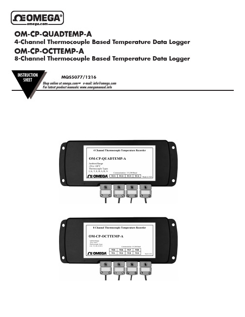
Xxxxx Xxxxxx XxxxxxxxOM-CP-OCTTEMP-A8-Channel Thermocouple Based Temperature Data LoggerProduct OverviewThe OM-CP-QUADTEMP-A is a four channelthermocouple temperature data logger with a readingrate of up to 4Hz. It can measure and record data forup to 500,000 readings per channel. To maximizememory capacity, users can disable unused channels toadd additional memory onto enabled channels. For easyidentification, each channel can be named with up toa ten digit title. In addition, the OM-CP-QUADTEMP-Afeatures individual cold junction compensation for eachchannel providing increased accuracy and responsetime, and if a probe is removed or severed duringlogging, the software automatically annotates the data.The OM-CP-QUADTEMP-A is ideal for a variety of applications, whether it is remote temperature monitoring, or multiple points in a central location. Data from all channels is simultaneously logged. After the monitoring cycle is complete, data can be downloaded for analysis. The OM-CP-QUADTEMP-A comes with a wall mounted 120/230VAC/9VDC 50/60HZ power adapter.Product OverviewThe OM-CP-OCTTEMP-A is an eight channelthermocouple data logger with a reading rate of up to4Hz. It can measure and record data for up to 500,000readings per channel. To maximize memory capacity,users can disable unused channels to add additionalmemory onto enabled channels. For easy identification,each channel can be named with up to a ten digit title.In addition, the OM-CP-OCTTEMP-A features individualcold junction compensation for each channel providingincreased accuracy and response time, and if a probeis removed or severed during logging, the softwareautomatically annotates the data.The OM-CP-OCTTEMP-A is ideal for a variety of applications, whether it is remote temperature monitoring, or multiple points in a central location. The OM-CP-OCTTEMP-A comes with a wall mounted 120/230VAC/9VDC 50/60HZ power adapter.Installation GuideInstalling the Interface cable- IFC200: Insert the device into a USB port. The drivers will install automatically.Installing the softwareInsert the Software USB Stick in an open USB port. If the autorun does not appear, locate the drive on the computer and double click on Autorun.exe. Follow the instructions provided in the Wizard.Device OperationConnecting and Starting the data logger- Once the software is installed and running, plug the interface cable into the data logger.- Connect the USB end of the interface cable into an open USB port on the computer.- The device will appear in the Connected Devices list, highlight the desired data logger.- For most applications, select “Custom Start” from the menu bar and choose the desired start method, reading rate and other parameters appropriate for the data logging application and click “Start”. (“Quick Start” applies the most recent custom start options, “Batch Start” is used for managing multiple loggers at once, “Real Time Start” stores the dataset as it records while connected to the logger.)- The status of the device will change to “Running”, “Waiting to Start” or “Waiting to Manual Start”, depending upon your start method.- Disconnect the data logger from the interface cable and place it in the environment to measure.Note: The device will stop recording data when the end of memory is reached or the device is stopped. At this point the device cannot be restarted until it has been re-armed by the computer.Downloading data from a data logger- Connect the logger to the interface cable.- Highlight the data logger in the Connected Devices list. Click “Stop” on the menu bar.- Once the data logger is stopped, with the logger highlighted, click “Download”. You will be prompted to name your report.- Downloading will offload and save all the recorded data to the PC.Wiring the Data LoggerWiring OptionsThe OM-CP-QUADTEMP-A has four SMP connections and the OM-CP-OCTTEMP-A has eight. These connections allow the user to insert subminiature thermocouple plugs into the connectors on the device. The diagram below shows how to connect the individual thermocouples for each of the devices.Warning: Note the polarity instructions. Do not attach wires to the wrong terminals.Additional Features and OperationManual StartWithin the software click the Custom Start button on the Device panel, or right-click on the device and hover on the start selection, then choose custom start. Apply the options desired and select Start to arm the device. Once the device is armed, activate the Manual Start by holding down the white recessed push button on the top of the device for 10 seconds. The green LED will begin to blink rapidly for 10 seconds, which signifies the push-button start has been activated. The green LED will continue to blink every 5 seconds. To see the change in the status, click Refresh Devices within the software.Enable/Disable ChannelsBy default, all channels are enabled.1. In the Connected Devices panel, click the device desired.2. On the Device Tab, in the Information Group, click Properties. Or, right-click the device and selectProperties in the context menu.3. Toggle the Enable Data Recording options for the thermocouple channels as desired.4. Apply these changes, there will be a prompt to reset the device, select yes.Note: When the checkmark is empty, the channel is disabled and will not record data or appear in the downloaded datasets. When the checkmark is clearly checked, it will be visible and record data.Thermocouple TypeTo change the thermocouple type:1. In the Connected Devices panel, click the device desired.2. On the Device Tab, in the Information Group, click Properties. Or, right-click the device and selectProperties in the context menu.3. On the General Tab, change the Thermocouple type in the drop down menu.4. Apply these changes, there will be a prompt to reset the device, select yes.LEDsSet PasswordTo password protect the device so that others cannot start, stop or reset the device;1. In the Connected Devices panel, click the device desired.2. On the Device Tab, in the Information Group, click Properties. Or, right-click the device and selectProperties in the context menu.3. On the General Tab, click Set Password.4. Enter and confirm the password in the box that appears, then select OK.To Change the PasswordTo change the password on the device so others can not stop, start or reset the device;1. In the Connected Devices panel, click the device desired.2. On the Device Tab, in the Information Group, click Properties. Or, right-click the device and selectProperties in the context menu.3. On the General Tab, click Change Password.4. Enter the old and new passwords in the box that appears, then select OK.To Clear the Password of a DeviceTo completely clear the password on a device so others can stop, start or reset the device;1. In the Connected Devices panel, click the device desired.2. On the Device Tab, in the Information Group, click Properties. Or, right-click the device and selectProperties in the context menu.3. On the General Tab, click Clear Password.4. Enter the password in the box that appears, then select OK.Channel NamingUp to a 10-character channel name can be programmed into the data logger for each channel. This ability helps to rename a channel in a report to distinguish it from other similarly named channels.1. In the Connected Devices panel, click the device desired.2. On the Device Tab, in the Information Group, click Properties. Or, right-click the device and selectProperties in the context menu.3. In the Channels panel, find the channel desired, then select “Use custom name.”4. This will prompt a space to type in a name.5. Select OK, then there will be a prompt to reset the device, select yes.Product MaintenanceBattery ReplacementMaterials:3/32” HEX Driver (Allen Key)Replacement Battery (OM-CP-BAT103)1. Remove the cover from the device by unscrewing the two screws.2. Remove the battery from its compartment and unsnap it from the connector.3. Snap the new battery into the terminals and verify it is secure.4. Replace the cover taking care not to pinch the wires. Screw the enclosure back together securely.Note: Be sure not to over tighten the screws or strip the threads.RecalibrationThe OM-CP-QUADTEMP-A or OM-CP-OCTTEMP-A standard calibration is one point at 25°C for the internalOM-CP-QUADTEMP-A General Specifications* Remote Channel Range, Resolution & AccuracyThermocouple Range (°C)Resolution Accuracy J-210 to +7600.1°C+0.5°CK-270 to +13700.1°C+0.5°CT-270 to +4000.1°C+0.5°CE-270 to +9800.1°C+0.5°CR-50 to +17600.5°C+2.0°CS-50 to +17600.5°C+2.0°CB+50 to +18200.5°C+2.0°CN-270 to +13000.1°C+0.5°CBattery WarningOM-CP-OCTTEMP-A General Specifications* Remote Channel Range, Resolution & AccuracyThermocouple Range (°C)Resolution Accuracy J-210 to +7600.1°C+0.5°CK-270 to +13700.1°C+0.5°CT-270 to +4000.1°C+0.5°CE-270 to +9800.1°C+0.5°CR-50 to +17600.5°C+2.0°CS-50 to +17600.5°C+2.0°CB+50 to +18200.5°C+2.0°CN-270 to +13000.1°C+0.5°CBattery WarningCompliance Information• “This device complies with Part 15 of the FCC Rules. Operation is subject to the following two conditions: (1) this device may not cause harmful interference, and (2) this device must accept any interference received, including interference that may cause undesired operation.”• “To satisfy FCC RF Exposure requirements for mobile and base station transmission devices, a separation distance of 20cm or more should be maintained between the antenna of this device and persons during operation. To ensure compliance, operation at closer than this distance is not recommended. The antenna(s) used for this transmitter must not be co-located or operating in conjunction with any other antenna or transmitter.”• “This device complies with Industry Canada license-exempt RSS standard(s). Operation is subject to the following two conditions: (1) this device may not cause interference, and (2) this device must accept any interference, including interference that may cause undesired operation of the device.Le présent appareil est conforme aux CNR d’Industrie Canada applicables aux appareils radio exempts de licence. L’exploitation est autorisée aux deux conditions suivantes: (1) l’appareil ne doit pas produire de brouillage, et (2) l’utilisateur de l’appareil doit accepter tout brouillage radioélectrique subi, même si le brouillage est susceptible d’en compromettre le fonctionnement.”• “Under Industry Canada regulations, this radio transmitter may only operate using an antenna of a type and maximum (or lesser) gain approved for the transmitter by Industry Canada. To reduce potential radio interference to other users, the antenna type and its gain should be so chosen that the equivalent isotropically radiated power (e.i.r.p.) is not more than that necessary for successful communication.Conformément à la réglementation d’Industrie Canada, le présent émetteur radio peut fonctionner avec une antenne d’un type et d’un gain maximal (ou inférieur) approuvé pour l’émetteur par Industrie Canada. Dans le but de réduire les risques de brouillage radioélectrique à l’intention des autres utilisateurs, il faut choisir le type d’antenne et son gain de sorte que la puissance isotrope rayonnée équivalente (p.i.r.e.) ne dépasse pas l’intensité nécessaire à l’établissement d’une communication satisfaisante.”WARRANTY/DISCLAIMEROMEGA ENGINEERING, INC. warrants this unit to be free of defects in materials and workmanship for a period of 13 months from date of purchase. OMEGA’s WARRANTY adds an additional one (1) month grace period to the normal one (1) year product warranty to cover handling and shipping time. This ensures that OMEGA’s customers receive maximum coverage on each product.If the unit malfunctions, it must be returned to the factory for evaluation. OMEGA’s Customer Service Department will issue an Authorized Return (AR) number immediately upon phone or written request. Upon examination by OMEGA, if the unit is found to be defective, it will be repaired or replaced at no charge. OMEGA’s WARRANT Y does not apply to defects resulting from any action of the purchaser, including but not limited to mishandling, improper interfacing, operation outside of design limits, improper repair, or unauthorized modification. This WARRANTY is VOID if the unit shows evidence of having been tampered with or shows evidence of having been damaged as a result of excessive corrosion; or current, heat, moisture or vibration; improper specification; misapplication; misuse or other operating conditions outside of OMEGA’s control. Components in which wear is not warranted, include but are not limited to contact points, fuses, and triacs.OMEGA is pleased to offer suggestions on the use of its various products. However, OMEGA neither assumes responsibility for any omissions or errors nor assumes liability for any damages that result from the use of its products in accordance with information provided by OMEGA, either verbal or written. OMEGA warrants only that the parts manufactured by the company will be as specified and free of defects. OMEGA MAKES NO OTHER W ARRANTIES OR REPRESENTATIONS OF ANY KIND W HATSOEVER, EXPRESSED OR IMPLIED, EXCEPT THAT OF TITLE, AND ALL IMPLIED W ARRANTIES INCLUDING ANY W ARRANTY OF MERCHANTABILITY AND FITNESS FOR A PARTICULAR PURPOSE ARE HEREBY DISCLAIMED. LIMITATION OF LIABILITY: The remedies of purchaser set forth herein are exclusive, and the total liability of OMEGA with respect to this order, whether based on contract, warranty, negligence, indemnification, strict liability or otherwise, shall not exceed the purchase price of the component upon which liability is based. In no event shall OMEGA be liable for consequential, incidental or special damages.CONDITIONS: Equipment sold by OMEGA is not intended to be used, nor shall it be used: (1) as a “Basic Component” under 10 CFR 21 (NRC), used in or with any nuclear installation or activity; or (2) in medical applications or used on humans. Should any Product(s) be used in or with any nuclear installation or activity, medical application, used on humans, or misused in any way, OMEGA assumes no responsibility as set forth in our basic WARRANTY / DISCLAIMER language, and, additionally, purchaser will indemnify OMEGA and hold OMEGA harmless from any liability or damage whatsoever arising out of the use of the Product(s) insuch a manner.FOR WARRANTY RETURNS, please have the following information available BEFORE contacting OMEGA:1. P urchase Order number under which the product was PURCHASED,2. M odel and serial number of the product under warranty, and3. R epair instructions and/or specific problems relative to the FOR NON-WARRANTY REPAIRS, consult OMEGA for current repair charges. Have the following information available BEFORE contacting OMEGA:1. Purchase Order number to cover the COST of the repair,2. Model and serial number of the product, and 3. R epair instructions and/or specific problems relative to the RETURN REQUESTS / INQUIRIESDirect all warranty and repair requests/inquiries to the OMEGA Customer Service Department. BEFORE RET URNING ANY PRODUCT (S) T O OMEGA, PURCHASER MUST OBT AIN AN AUT HORIZED RET URN (AR) NUMBER FROM OMEGA’S CUST OMER SERVICE DEPARTMENT (IN ORDER TO AVOID PROCESSING DELAYS). The assigned AR number should then be marked on the outside of the return package and on any correspondence.The purchaser is responsible for shipping charges, freight, insurance and proper packaging to prevent breakage in transit.The information contained in this document is believed to be correct, but OMEGA accepts no liability for any errors it contains, and reserves the right to alter specifications without notice.Servicing North America:U.S.A. Omega Engineering, Inc. Headquarters: Toll-Free: 1-800-826-6342 (USA & Canada only) Customer Service: 1-800-622-2378 (USA & Canada only) Engineering Service: 1-800-872-9436 (USA & Canada only) Tel: (203) 359-1660 Fax: (203) 359-7700 e-mail:**************For Other Locations Visit /worldwide ***********************。
Omega OM-CP-RFOT-A 无线肉质温度数据记录器外部探头说明书

OM-CP-RFOT-AWireless Meat Temperature Data Logger with External ProbeXxxxx Xxxxxx Xxxxxxxx1. Install the OM-CP Data Logger Software and USB Drivers onto a Windows PC.2. The OM-CP-RFC1000-EXT interface device comes with a USB cable. Plug one end of the cable into an available USB port on the PCand plug the opposite end of the cable into the communication port on the OM-CP-RFC1000-EXT.3. The OM-CP-RFOT-A is shipped with wireless transmission in an active, low power state. During normal use, inserting a USB (microB type) cable into the OM-CP-RFOT-A will pass control to the OM-CP software and disable the wireless transmission. When the USB cable is unplugged, wireless transmission is resumes with settings that were chosen in the OM-CP software.4. Launch the OM-CP Data Logger Software. All active Omega Data Loggers that are within range will automatically appear in theconnected devices window. Each data logger in the list can be identified by serial number (imprinted on the probe handle of the logger).5. Select the data logger within the Connected Devices window and click the Claim icon.6. Select the start method, reading rate and any other parameters appropriate for the desired data logging application. Onceconfigured, deploy the data logger by clicking Start .7. To download data, select the device in the list, click the Stop icon, and then click the Download icon. A graph will automaticallydisplay the data.Quick Start StepsOM-CP Data Logger SoftwareA Complete Wireless Data Logging SystemData LoggerInterface Device &USB CableUSB Cable(Included accessory with OM-CP-RFC1000-EXT)Power Adapter(Included accessory with OM-CP-RFC1000-EXT)OM-CP-RFOT-A Wireless Data LoggerOM-CP-RFC1000-EXTWireless TransceiverOM-CP-RFOT-A Product OverviewThe Omega OM-CP-RFOT-A is a two-way wireless meat cooking and cooling data logger. The OM-CP-RFOT-A’s rugged design, equipped with a flexible piercing probe allows it to be used in harsh environments. The OM-CP-RFOT-A is perfectly suited for use in smoke houses, ovens and other cooking processes up to 212 °F (100 °C) as well as refrigerators and freezers down to -4 °F (-20 °C). The OM-CP-RFOT-A is completely splash proof, and can withstand wash down cycles. The OM-CP-RFOT-A records and transmits internal product temperature readings back to a central PC for instant real-time monitoring, even when a smoke house or freezer door is closed.The OM-CP-RFOT-A allows the user to also set-up real-time wireless alarming within the software, so that the user is notified by email or text if an alarm condition has been met or exceeded. The OM-CP-RFOT-A assists in complying with HACCP requirements as well as USDA regulations.OM-CP-BAT1093.6V Lithium Battery.OM-CP-RFOT-A Options & AccessoriesProbeSoftware InstallationInstalling the OM-CP Data Logger SoftwareInsert the OM-CP Data Logger Software Flash Drive into an open USB port on a Windows PC. If the autorun does not appear, locate the drive on the computer and double click on Autorun.exe. Follow the instructions provided in the Installation Wizard.Locate the Autorun.exe file on theOM-CP Data Logger Software Flash Drive.Select “Omega Software” in the Omega Installer Options window panel.If the Windows PC doesn’t already have .NET 4.0 Framework, installation may be required.To see if the .NET 4.0 Framework is installed, go to the Windows Control Panel and select Programs. “Microsoft .NET Framework 4.0” would be listed as a Windows program.Select “Install Omega Software” if .NET framework is installed on the Windows PC, or if installing on a Windows 8 machine.3Once the installation of the software and driver is confirmed, the OM-CP-RFC1000-EXT canthen be connected to the computer.Select “Driver and Third Party Tools” in the Omega Installer Options window panel.Installing the USB DriverWith the USB Flash Drive inserted into the computer, locate the drive on the computer and double click on Autorun.exe . Install the USB Interface Drivers (under Drivers and Third Party Tools).Activating & Deploying the Data Logger1. Connect the OM-CP-RFC1000-EXT wireless transceiver (sold separately) to the Windows PC with the provided USB cable.2. Additional OM-CP-RFC1000-EXT’s can be used as repeaters to transmit over greater distances or to maintain signal if walls, corners,or other obstacles impede line of sight. Plug each one into an electrical outlet in the desired locations.3. Launch the OM-CP Data Logger Software.4. The OM-CP-RFOT-A is shipped with wireless transmission in an active, low power state.Inserting a USB (micro B type) cable into the OM-CP-RFOT-A enables direct USB communicationand disables wireless transmission. Direct USB communication allows for changing the wirelesschannel in the device’s Properties, if necessary.5. When the USB cable is unplugged, wireless transmission is enabled.6. All active data loggers will be listed within the Connected Devices panel. Select a logger, and click the Claim icon to pair the loggerto the OM-CP-RFC1000-EXT connected to the PC.7. Choose the start method, either Real Time Start to view data as it is collected, or Custom Start for standalone logging to memory.By default, a report is generated automatically when starting a logger using Real Time Start. With Custom Start, data is recorded to memory and can be viewed by selecting Stop to end the cycle, and Download to retrieve the data from the logger’s internal memory. Mounting InstructionsFor best performance, the OM-CP-RFOT-A should always be hung by the hook in an upright position. This will allow for the best path for the wireless signal.Transmission DistanceTypical transmission distance from an OM-CP-RFC1000-EXT to an OM-CP-RFOT-A:• Unobstructed line of sight (outdoors): 2,000 feet max• Typical urban environment (indoors): 500 feet maxObstaclesObstacles will decrease the line-of-sight from an OM-CP-RFC1000-EXT to another OM-CP-RFC1000-EXT as well as from an OM-CP-RFC1000-EXT to an OM-CP-RFOT-A. Obstacles that interfere with or decrease the wireless signal could include but are not limited to smokehouse doors, freezer/refrigerator doors, building structures such as walls and metal beams and internal traffic such as forklifts and metal racks or carts. Additional OM-CP-RFC1000-EXT’s can be placed near obstacles to lengthen and strengthen the wireless signal.DeflectionWhen a wireless signal “hits” an object such as a metal wall, the wireless signal will not just stop but rather it could turn a corner, bend or slow down. When installing the OM-CP-RFC1000-EXT’s obstacles and possible deflection should also be considered.Channel ProgrammingDifferent wireless channels may be used to create multiple networks in one area, or to avoid wireless interference from other devices. Any data logger or OM-CP-RFC1000-EXT wireless transceiver that is on the same network is required to use the same channel. If all of the devices are not on the same channel, the devices will not communicate with one another. OM-CP-RFC1000-EXT wireless transceivers are programmed by default on channel 25.CHANNEL NOTE: Omega wireless data loggers and wireless transceivers purchased prior to April 15, 2016 are programmed by default to channel 11. Please refer to the Product User Guide provided with these devices for instructions to change the channel selection if needed.Changing the channel settings of the OM-CP-RFOT-AConnect the OM-CP-RFOT-A to the PC with a USB cable. In the OM-CP Data Logger Software, select a device from the connected devices window, then click the properties icon at the top of screen, or, right click on a device in the connected devices window and select properties. On the properties screen, select Wireless and in the Wireless Channel box, click the down arrow, then the desired channel. Click OK to confirm the choice.Be sure that the channel chosen matches the channel settings of the OM-CP-RFC1000-EXT wireless transceiver which this device willcommunicate through. To configuring the channel settings of the OM-CP-RFC1000-EXT wireless transceiver (sold separately), please refer to the OM-CP-RFC1000-EXT Product User Guide.TroubleshootingWhy is the wireless data logger not appearing in the OM-CP Data Logger Software?If the data logger doesn’t appear in the Connected Devices panel, or an error message is received while using the data logger, try the following:• Ensure the data logger and OM-CP-RFC1000-EXT are on the same wireless channel. If the devices are not on the same channel, the devices will not communicate with one another. Please refer to the Channel Programming section for information on changing the device channel.• Check that the OM-CP-RFC1000-EXT is properly connected.• Ensure that the battery is not discharged. For best voltage accuracy, use a voltage meter connected to the battery of the device. If possible, replace battery.• Ensure that the Omega 4 Software is being used.• Ensure that the Connected Devices panel is large enough to display devices. This can be verified by positioning the cursor on the edge of the Connected Devices panel until the resize cursor appears, then dragging the edge of the panel to resize it.OM-CP-RFOT New PropertiesWIRELESS DIAGRAMfor the OM-CP-RFOT-A Data LoggersOM-CP-RFOT-AMeat TemperatureData LoggerNote: The OM-CP-RFOT-A can be placeddirectly in an oven/smoke house.OM-CP-RFC1000-EXTConnected to a Power OutletOM-CP-RFC1000-EXTConnected to a USB PortProduct MaintenanceBattery ReplacementMaterials needed: OM-CP-BAT109 Replacement BatteryProcedure:1. Unscrew the end cap from the logger.2. Remove the battery retention clip by sliding a small screwdriver blade or paper clip betweenthe clip and battery holder and prying away from the holder.3. Grasp the black base of the unit with cord hanging downward and both edges of the circuit board, all with one hand. Pull the old battery out with the other hand.4. Install a new battery, observing the polarity markings on the circuit board and battery holder. Position the battery retention clip over the new battery and install by pressing downward until a click is heard from each side5. Install the new battery as shown by the diagram on the bottom of the battery holder.6. Screw the body of the logger back together making sure the O-Rings are not visible.Battery WarningDISCARD USED BATTERY PROMPTLY. KEEP OUT OF REACH OF CHILDREN. DO NOT DISPOSE OF IN FIRE, RECHARGE, PUT IN BACKWARDS, DISASSEMBLE, OR MIX WITH OTHER BATTERY TYPES. MAY EXPLODE, FLAME, OR LEAK AND CAUSE PERSONAL INJURY.O-Ring Maintenance:Omega data loggers come directly from the factory with high quality O-Rings that have been properly installed. As a user, there are only a few things that need to be remembered to maintain a functional O-Ring seal.DO:• Clean them frequently (use compressed air or a soft brush to avoid abrasion).• Lubricate regularly (if it doesn’t feel slippery, it needs to be lubricated). We recommend Parker ® Super-O-Lube, but any silicone based O-Ring lubricant will work. This is most important on the seals that are frequently opened and closed for communication with the logger.• Inspect the O-Ring regularly for signs of failure (see the reverse side of this pamphlet for details on what to look for)(Battery compartment shown with cover removed)3.6V lithium batteryDON’T:• Poke, jab, pry at the O-Ring with sharp or pointed objects.• Expose the O-Rings to harsh chemicals (when in doubt, call Omega).• Expose the seals to high pressure (all of Omega’s submersible data loggers are rated to 60 PSIG).• Expose the seal to high temperatures (see data logger Specification Sheet for operating temperature range).RecalibrationRecalibration is recommended annually for all Omega data loggers. The Properties window in the OM-CP Data Logger software displays the date of the last calibration and the date that the device is next due for calibration. The OM-CP Data Logger Software can also be configured to send an on screen notification prior to the calibration due date for each device. By default this is set to seven days prior to calibration due date and can be changed by the user by going to the file tab in the OM-CP Data Logger software and clicking on Options . Select device and check “Display popup notification when a device nears its next calibration date ”. The user can then select the number of days before calibration due date to notify.General SpecificationsTemperatureWirelessOM-CP-RFOT-A SpecificationsCountries approved for use, purchase and distribution of the OM-CP-RFOT-A:Australia, Austria, Belgium, Bulgaria, Canada, Chile, Colombia, Croatia, Cyprus, Czech Republic, Denmark, Ecuador, Estonia, Finland, France, Germany, Greece, Honduras, Hungary, Iceland, Ireland, Israel, Japan, Latvia, Liechtenstein, Lithuania, Luxembourg, Malaysia, Malta, Mexico, New Zealand, Norway, Peru, Poland, Portugal, Romania, Saudi Arabia, Singapore, Slovakia, Slovenia, South Africa, Battery WarningBATTERY MAY LEAK, FLAME OR EXPLODE IF DISASSEMBLED, SHORTED, CHARGED, CONNECTED TOGETHER, MIXED WITH USED OR OTHER BATTERIES, EXPOSED TO FIRE OR HIGH TEMPERATURE. DISCARD USED BATTERY PROMPTLY. KEEP OUT OF REACH OF CHILDREN.Specifications subject to change.See Omega’s terms and conditions at .WARRANTY/DISCLAIMEROMEGA ENGINEERING, INC. warrants this unit to be free of defects in materials and workmanship for a period of 13 months from date of purchase. OMEGA’s WARRANTY adds an additional one (1) month grace period to the normal one (1) year product warranty to cover handling and shipping time. This ensures that OMEGA’s customers receive maximum coverage on each product.If the unit malfunctions, it must be returned to the factory for evaluation. OMEGA’s Customer Service Department will issue an Authorized Return (AR) number immediately upon phone or written request. Upon examination by OMEGA, if the unit is found to be defective, it will be repaired or replaced at no charge. OMEGA’s WARRANT Y does not apply to defects resulting from any action of the purchaser, including but not limited to mishandling, improper interfacing, operation outside of design limits, improper repair, or unauthorized modification. This WARRANTY is VOID if the unit shows evidence of having been tampered with or shows evidence of having been damaged as a result of excessive corrosion; or current, heat, moisture or vibration; improper specification; misapplication; misuse or other operating conditions outside of OMEGA’s control. Components in which wear is not warranted, include but are not limited to contact points, fuses, and triacs.OMEGA is pleased to offer suggestions on the use of its various products. However, OMEGA neither assumes responsibility for any omissions or errors nor assumes liability for any damages that result from the use of its products in accordance with information provided by OMEGA, either verbal or written. OMEGA warrants only that the parts manufactured by the company will be as specified and free of defects. OMEGA MAKES NO OTHER W ARRANTIES OR REPRESENTATIONS OF ANY KIND W HATSOEVER, EXPRESSED OR IMPLIED, EXCEPT THAT OF TITLE, AND ALL IMPLIED W ARRANTIES INCLUDING ANY W ARRANTY OF MERCHANTABILITY AND FITNESS FOR A PARTICULAR PURPOSE ARE HEREBY DISCLAIMED. LIMITATION OF LIABILITY: The remedies of purchaser set forth herein are exclusive, and the total liability of OMEGA with respect to this order, whether based on contract, warranty, negligence, indemnification, strict liability or otherwise, shall not exceed the purchase price of the component upon which liability is based. In no event shall OMEGA be liable for consequential, incidental or special damages.CONDITIONS: Equipment sold by OMEGA is not intended to be used, nor shall it be used: (1) as a “Basic Component” under 10 CFR 21 (NRC), used in or with any nuclear installation or activity; or (2) in medical applications or used on humans. Should any Product(s) be used in or with any nuclear installation or activity, medical application, used on humans, or misused in any way, OMEGA assumes no responsibility as set forth in our basic WARRANTY / DISCLAIMER language, and, additionally, purchaser will indemnify OMEGA and hold OMEGA harmless from any liability or damage whatsoever arising out of the use of the Product(s) insuch a manner.FOR WARRANTY RETURNS, please have the following information available BEFORE contacting OMEGA:1. P urchase Order number under which the product was PURCHASED,2. M odel and serial number of the product under warranty, and 3. R epair instructions and/or specific problems relative to the product.FOR NON-WARRANTY REPAIRS, consult OMEGA for current repair charges. Have the following information available BEFORE contacting OMEGA:1. Purchase Order number to cover the COST of the repair,2. Model and serial number of the product, and3. R epair instructions and/or specific problems relative to the product.OMEGA’s policy is to make running changes, not model changes, whenever an improvement is possible. T his affords our customers the latest in technology and engineering. OMEGA is a registered trademark of OMEGA ENGINEERING, INC.RETURN REQUESTS / INQUIRIESDirect all warranty and repair requests/inquiries to the OMEGA Customer Service Department. BEFORE RET URNING ANY PRODUCT (S) T O OMEGA, PURCHASER MUST OBT AIN AN AUT HORIZED RET URN (AR) NUMBER FROM OMEGA’S CUST OMER SERVICE DEPARTMENT (IN ORDER TO AVOID PROCESSING DELAYS). The assigned AR number should then be marked on the outside of the return package and on any correspondence.The purchaser is responsible for shipping charges, freight, insurance and proper packaging to prevent breakage in transit.The information contained in this document is believed to be correct, but OMEGA accepts no liability for any errors it contains, and reserves theright to alter specifications without notice.Servicing North America:U.S.A.Omega Engineering, Inc.Headquarters:Toll-Free: 1-800-826-6342 (USA & Canada only)Customer Service: 1-800-622-2378 (USA & Canada only) Engineering Service: 1-800-872-9436 (USA & Canada only) Tel: (203) 359-1660 Fax: (203) 359-7700 e-mail:**************For Other Locations Visit /worldwide***********************TM。
OMC介绍

OMC操作维护
1
ZTE Confidential Proprietary
OMC操作维护 OMC操作维护
系统概述 日常操作 性能管理
2
ZTE Confidential Proprietary
OMC操作维护 OMC操作维护 系统概述
网管简介 NetNumen M31 组网结构
性能数据提取 信令跟踪
11
ZTE Confidential Proprietary
告警管理
12
ZTE Confidential Proprietary
信令跟踪
添加IP
13
ZTE Confidential Proprietary
心得 做比说有用多了 胆大心细就可以应付一切 随时欢迎各位
14
ZTE Confidential Proprietary
硬件组网结构
6
ZTE Confidential Proprietary
OMC操作维护 OMC操作维护 系统概述 日常操作
启动客户端 主界面 配置管理 告警管理
性能管理
7
ZTE Confidential Proprietary
系统操作 客户端的启动和退出 添加和服务器在同一网段的IP 用户名:zte; 密码:zte_3g 主界面
谢谢 !
15
ZTE Confidential Proprietary
日常操作 性能管理
3
ZTE Confidential Proprietary
何为网管? 何为网管?
OMC:Operating and Maintenance Center
支持整个企业决策的管理 提供业务管理 从全网观点控制所有网元 对多个网元的操作管理
- 1、下载文档前请自行甄别文档内容的完整性,平台不提供额外的编辑、内容补充、找答案等附加服务。
- 2、"仅部分预览"的文档,不可在线预览部分如存在完整性等问题,可反馈申请退款(可完整预览的文档不适用该条件!)。
- 3、如文档侵犯您的权益,请联系客服反馈,我们会尽快为您处理(人工客服工作时间:9:00-18:30)。
OMC V01B01R01D04SP2版本特性说明
版本信息
产品名称: OMC集中管理平台
OMC SHELL : OMC V01R01B01D04SP2
主机版本 : 无
说明
本版本支持:
IONE:OMU V02R00B06D03SP3 主机:V02R00B06D03SP3
SOFTUP:OAM V02R00B13D07SP9 主机:V02R00B13D07SP8 (目前还没发布市场)
以及以后的版本,支持MX+AG的混合组网模式(必须要IONE和SoftUp相应版本的支持)。
新增特性说明
无
删除的特性说明
无
此版本当前支持特性列表
建议使用的网管配套版本
IONE:OMU V02R00B06D03SP3 主机:V02R00B06D03SP3 或更新的版本SOFTUP:OAM V02R00B13D07SP9 主机:V02R00B13D07SP8 或更新的版本
维护多个区域的设备
因为目前不支持在同一台PC上安装同一产品的不同版本。
而OMC在维护设备时,是通过调用SoftUp或IONE的网管客户端程序进行维护的。
所以,在维护多个区域的设备时,必须要求这些区域的SoftUp产品或IONE产品的版本号相同。
用户、设备组、工作站
正常情况下,在同一区域中,IONE和SoftUp的用户、设备组、工作站数据是一致。
若数据出现了不一致的情况(如:用户A在SoftUp中被配置,却没有在IONE中配置),可能引起一些问题。
出现数据不一致的情况时,解决办法:
1.可以通过telnet的方法,连接到区域中具体产品的网管服务器,然后手动将所有产品的用户、设备组、工作站数据配置成一致的。
SoftUp网管(OAM)服务器的telnet端口号:23; IONE网管(OMU)服务器的telnet端口号:6023
2.删除不一致的数据,重新配置这些数据。
设备ID的配置
现有的版本中,为设备组配置设备时,能配置的最大设备ID为1023,ID超过此值的设备无法加入到设备组中,所以,在配置新的设备时,建议将设备的ID范围定在1-1023之内(包括MX/AX/TCG/AG/IAD)。
另外,用户在配置设备时,IONE和SoftUp的网管服务器,都会对设备ID进行唯一性验证:若某个ID值在SoftUp中被一AG使用,在IONE中就不能配置相同ID值的MX或AX或别的设备;同样,IONE中配置了某个ID值的MX,SoftUp中就不能配置与这个ID相同的设备。
系统配置要求
硬件环境
安装OMC系统可以是一台PC,最低配置如下:
Pentum 266或同等性能的CPU
128M 存储器
20M 剩余磁盘空间
一块Ethernet以太网网卡
操作系统:Win2000系列
网络环境
可以是Internet、城域网、Intranet,但是对于后两者必须保证能和OAM或OMU服务器建立逻辑连接。