(asce)cf.1943-5509.0000504
ASME锅炉及压力容器规范

ASME锅炉及压力容器规范A篇铁基材料SA-6/SA-6M 轧制结构钢棒材、钢板、型材和薄板板桩的通用要求。
SA-20/SA-20M 压力容器用钢板通用要求。
SA-29/SA-29M 热加工与冷精整碳钢和合金钢棒材通用要求。
SA-36/SA-36M 碳素结构钢。
SA-47/SA-47M 铁素体可锻铸铁件。
SA-53/A-53M 无镀层及热浸镀锌焊接与无缝公称钢管。
SA-105/SA105M 管道元件用碳钢锻件。
SA-106 高温用无缝碳钢公称管。
SA-134 电弧溶焊公称钢管。
(规格不小于NPS16)SA-135 电阻焊公称钢管。
SA-178/SA-178M 电阻焊碳钢和碳锰钢锅炉及过热器管子。
SA-179/SA-179M 换热器及冷凝器用无缝冷拔低碳钢管子。
SA-181/SA-181M 一般管道用碳钢锻件。
SA-182/SA-182M 高温用锻制或轧制合金钢公称管道法兰、锻制管配件、阀门和零件。
SA-192/SA-192M 高压用无缝碳钢锅炉管子。
SA-193/SA-193M 高温用合金钢和不锈钢螺栓材料。
SA-194/SA-194M 高温高压螺栓用碳钢和合金钢螺母。
SA-202/SA-202M 压力容器用铬锰硅合金钢板。
SA-203/SA-203M 压力容器用镍合金钢板。
SA-204/SA-204M 压力容器用钼合金钢板。
SA-209/SA-209M 锅炉和过热器用无缝碳钼合金钢管子。
SA-210/SA-210M 锅炉和过热器用无缝中碳钢管子。
SA-213/SA-213M 锅炉、过热器和换热器用无缝铁素体和奥氏体合金钢管子。
SA-214/SA-214M 换热器和冷凝器用电阻焊碳钢管子。
SA-216/SA-216M 可溶焊高温用碳钢铸件。
SA-217/SA-217M 高温承压零件用马氏体不锈钢和合金钢铸件。
SA-225/SA-225M 压力容器用锰钒镍合金钢板。
SA-231/SA-231M 铬钒合金钢弹簧钢丝。
德国材料标准对照表
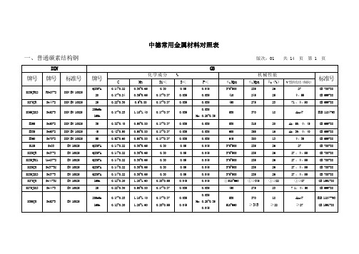
中德常用金属材料对照表
一、普通碳素结构钢版次:01 共 14 页第 1 页
一、碳素结构钢版次:01 共 14 页第 2 页
注:
(a)V:调质处理;
(b)①为调质处理时参数。
一、碳素结构钢版次:01 共 14 页第 3 页
注:
N:正火。
二、合金结构钢版次:01 共 14 页第 4 页
①截面≤100时,调质;②截面≤ 120时,调质;③截面 15时,调质;④截面25时,调质;⑤截面30时,调质。
三、灰口铸铁:球墨铸铁Grey cast iron;nodular cast irou版次:01 共 14 页第 5页
四、铸钢 Casting steel版次:01 共 14 页第 6 页
四、铸钢 Casting steel版次:01 共 14 页第 7 页
注:①正火+回火;②调质。
六、弹簧钢Spring steel 版次:01 共14 页第9 页
七、无缝钢管用碳素钢 Carbon steel for seamless steel tube版次:01 共 14 页第 10 页
八、有色金属材料 non-ferrous metal maerial 版次:01 共 14 页第11 页
八、有色金属材料 non-ferrous metal maerial版次:01 共 14 页第13 页
注:S—砂型铸造;J—金属型铸造;Li—离心铸造;La—连续铸造
九、轴承钢 Bearing Steel 版次:01 共 14 页第 14 页。
ASCO Pneumatic Valves 3 2 - 5 2 - 5 3 - NAMUR 产品说明
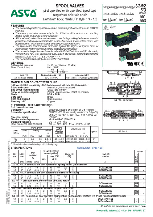
All leaflets are available on: Pneumatic Valves (3/2 - 5/2 - 5/3 - NAMUR) 57FEATURES• The solenoid operated spool valves have threaded port connections and NAMUR interface• The same spool valve can be adapted for 3/2 NC or 5/2 functions for controlling double-acting and single-acting actuators• All the exhaust ports of the spool valve are connectable, providing better environmental protection. Particularly recommended for sensitive areas, such as clean rooms, and applications in the pharmaceutical and food processing sectors• The valves offer environmental protection against the ingress of liquids, dusts or other foreign matter (environmentally-protected construction)• The monostable spool valves in conformity with IEC 61508 Standard (2010 route 2H version) have TÜV (551 series) and EXIDA (551-553 series) certified with integrity levels: SIL 2 for HFT = 0 / SIL 3 for HFT = 1• The solenoid valves satisfy all relevant EU directivesGENERALDifferential pressure 2 - 10 bar [1 bar = 100 kPa]Flow (Qv at 6 bar)l/min (ANR)1/41/27003000fluids ( )temperature range (TS)seal materials ( )air, inert gas, filtered-25°C to +60°C NBR (nitrile) + PUR (polyurethane)MATERIALS IN CONTACT WITH FLUID( ) Ensure that the compatibility of the fluids in contact with the materials is verifiedBody, end coverAluminium, black anodized End cover (spring return) Glass fibre filled P ASpool valve internal parts Zamak, stainless steel, POM, aluminium SealsNBR + PUR Core tubeBrassCore and plugnut Stainless steel Shading coilCopperELECTRICAL CHARACTERISTICSCoil insulation class F Connector Spade plug (cable Ø 6-8 mm or Ø 6-10 mm)Connector specification EN 175301-803, 11 mm, industry standard form B (type 01) or ISO 4400 / EN 175301-803, form A (type 02)Electrical safety IEC 335Electrical enclosure protection Moulded IP65 (EN 60529)Standard voltages DC (=): 24V - 48V (Other voltages and 60 Hz on request) AC (~): 24V - 48V - 115V - 230V / 50 Hzprefix option power ratings operator ambient temperature range (TS)replacement coil type (1)inrush ~holding ~hot/cold=~=(VA)(VA)(W)(W)(C°)230 V/50 Hz 24 V DC SC 63,52,52,5 / 3-25 to +60400127-097400904-54201SC15754 / 5-25 to +60400727-117400727-18502(1)Refer to the dimensional drawings on the following pageSPECIFICATIONSpipe size orifice size flow coefficientKv operating pressure differential (bar)power coil (W)catalogue number optionsm a i n t a i n e d m a n . o p e r a t o rmin.max . (PS)air (*)G (mm)(m 3/h)(l/min)~=~=~/=3/2 NC - 5/2 - Solenoid air pilot operated - spring return (monostable)1/460,610210102,53SCG551A001MS --1/2132,4941,52101055SCG553A001MS --3/2 NC - 5/2 - Solenoid air pilot operated and return (bistable)1/460,610210102,53SCG551A002MS --1/2132,4941,52101055SCG553A002MS --5/3 - W1 - pressure held, solenoid air pilot and return1/460,610210102,53SCG551A065MS --1/2132,4941,52101055SCG553A065MS --5/3 - W3 - pressure released, solenoid air pilot and return1/460,610210102,53SCG551A066MS --1/2132,4941,52101055SCG553A066MS --3/2 NC - 5/2 - Solenoid air pilot operated spring return (monostable), certified IEC 61508 Functional Safety data1/460,610210102,53SCG551A001SL ---1/2132,4941,52101055SCG553A001SL---152400095G B -2017/R 01A v a i l a b i l i t y , d e s i g n a n d s p e c i fi c a t i o n s a r e s u b j e c t t o c h a n g e w i t h o u t n o t i c e . A l l r i g h t s r e s e r v e d .SPOOL VALVESpilot operated or air operated, spool typesingle/dual solenoid or airaluminium body, “NAMUR” style, 1/4 - 1/25/3Séries 551Configurator - CAD FilesAIR OPERATED AND OPTIONS• Versions (T ype 03):- p ilot air operated, spring return, catalogue numbers: G551A101 / G551A101SL (1/4); G553A101 / G553A101SL (1/2)- pilot air operated and return, catalogue numbers: G551A102 (1/4); G553A102 (1/2)• Suffix “MF “ (air operated only, low temperature version, -40°C)• Suffix “GD “ (air operated only, A TEX 2GD c)• Explosionproof enclosures for use in zones 1/21-2/22, categories 2-3 to ATEX Directive 2014/34/EU (see “Explosionproof solenoids” section)• Valves equipped with exhaust reducers G 1/8 (3/2 NC-5/2, series 551), suffix M MS • Set of stainless steel mounting screws (series 551), catalogue number 97802212• Set of two G 1/8 exhaust reducers (series 551), catalogue number 88100344• Other pipe connections are available on request• Plug with visual indication and peak voltage suppression or with cable length of 2 m (see Solenoids, Coils & Accessories section)INSTALLATION• The valves can be mounted in any position without affecting operation• 3/2 NC-5/2 spool valve supplied with one or two interface plates with NAMUR mating surfaces. Depending on function (3/2 NC or 5/2), position the plate (series 551) or one of the two plates (series 553) on the spool valve body before installing on actuator• Do not connect the pressure supply to the exhaust port 3. The “environmentally-protected” construction is not adapted for NO function. Contact us for function available in specific version• Dowel pin (if necessary), bolts and gaskets are standard supplied• It is necessary to connect pipes or fittings to the exhaust ports to protect the internal parts of the spool valve and its pneumatic operator if used outside or in harsh environments (dusts, liquids etc.)• IEC 61508 Functional Safety (suffix SL). Check temperature range of valve body and solenoid for suitability. For probability of failure, contact us• Threaded pipe connection is standard: G = G (ISO 228/1)• Valves with suffix “SL ” are supplied with specific exhaust protectors • Installation/maintenance instructions are included with each valveACCESSORIESseries pipe sizeexhaust protector (stainless steel )551G 1/834600418 (1)551 (W1/W3)G 1/434600419553 G 1/234600479 (1)551-553M534600484 (1)(1)Supplied with suffix “SL ”ORDERING EXAMPLES:SC G 551 A 001MS 230V /50 Hz SC G 551 A 001SL 24V /DC SC G 553 A 002115V /50 HzG 551 A 101SLprefix pipe thread voltage basic numbersuffixDIMENSIONS (mm), WEIGHT (kg)SERIES 551-553TYPE 02Prefix “SC” Solenoid Epoxy moulded IEC 335 / ISO 4400IP65553A001/A001MS /A001SL /A002/A002MS 551A065/A065MS /A066/A066MS00095G B -2017/R 01A v a i l a b i l i t y , d e s i g n a n d s p e c i fi c a t i o n s a r e s u b j e c t t o c h a n g e w i t h o u t n o t i c e . A l l r i g h t s r e s e r v e d .TYPE 01Prefix “SC” Solenoid Epoxy mouldedIEC 335 / DIN 43650IP65551A001/A001MS /A001SL /A002/A002MSConfigurator - CAD FilesAll leaflets are available on: Pneumatic Valves (3/2 - 5/2 - NAMUR) - 59FEATURES• The solenoid operated spool valves have threaded port connections and NAMUR interface • The same spool valve can be adapted for 3/2 NC or 5/2 functions for controlling double-acting and single-acting actuators• All the exhaust ports of the spool valve are connectable, providing better environmental protection. Particularly recommended for sensitive areas, such as clean rooms, and applications in the pharmaceutical and food processing sectors• The valves offer environmental protection against the ingress of liquids, dusts or other foreign matter (environmentally-protected construction)• Solenoid pilot valve with spade-plug connector type EN 175301-803, industry standard form C, with 9,4 mm spacing. Versions with M12 connection• Solenoid pilot valve, CNOMO size 15 interface, with or without integral LED and electrical protection. LED indicator visible from 3 sides• The monostable spool valves in conformity with IEC 61508 Standard (2010 route 2H version) have TÜV (551 series) and EXIDA (551-553 series) certified with integrity levels: SIL 2 for HFT = 0 / SIL 3 for HFT = 1• The solenoid valves satisfy all relevant EU directivesGENERALDifferential pressure 2 - 10 bar [1 bar = 100 kPa]Flow (Qv at 6 bar)l/min (ANR)1/41/27003000Pilot mounting interface surfaceISO 15218 (CNOMO E06.36.120N, size 15)fluids ( )temperature range (TS)seal materials ( )air, inert gas, filtered-25°C to +40°CNBR (nitrile) + PUR (polyurethane)MATERIALS IN CONTACT WITH FLUID( ) Ensure that the compatibility of the fluids in contact with the materials is verifiedBody Aluminium, black anodized End cover (spring) Glass fibre filled P A Interface plates Glass fibre filled P A Spool valve internal parts Zamak, stainless steel, POM, aluminium Pilot body P ARA Pilot internal parts POM, PET , stainless steel and brass Pneumatic interface seal TPEELECTRICAL CHARACTERISTICSCoil insulation class FConnector (type 05)Spade plug (cable Ø 4-6 mm)Connector specification Type 05: DIN 43650, 9,4 mm, form C ConnectionT ype 07: M12 (CNOMO E03.62.520.N)Electrical safetyIEC 335Electrical enclosure protection Moulded IP65 [05] or IP67 [07] (EN 60529) Standard voltagesDC (=): 24V(Other voltages and 60 Hz on request)AC (~): 24V-115V-230V / 50 Hz (prefix CFSC)prefix optionpower ratings operator ambient temperature range (TS)voltage type (1)inrush ~holding ~hot/cold =~=(VA)(VA)(W)(W)(C°)(V)(V)CFSC 1,41,21,11/1,2-25 to +6024-11524051,8 (2)1,6 (2)1,5 (2)1,15/1,35(2)2,11,61,5--25 to +60230-2,5 (2)2 (2)1,9 (2)--25 to +50CFVT (3)---1,15/1,35-25 to +60-2407(1) Refer to the dimensional drawings on the following page.(2)Values with LED indicator and protection, use TPL 20674.(3)Supplied with LED indicator and protection.SPECIFICATIONSpipe size orifice size flow coefficientKv operating pressure differential (bar)power coil(W)catalogue numberoptionsconnectorEN 175301-803 (9,4 mm)M12m a i n t a i n e d m a n . o p e r a t o ri m p u l s e m a n . o p e r a t o rmin.max . (PS)air (*)(type 05)(type 07)G (mm)(m 3/h)(l/min)~=~=~/==3/2 NC - 5/2 - Solenoid air pilot operated - spring return (monostable)1/460,610210101,1..1,51,2CFSCG551C501-MS MO --1,35-CFVT G551C501MS MO -1/2132,4941,5210101,1..1,51,2CFSCG553A501-MS MO --1,35-CFVT G553A501MS MO -3/2 NC - 5/2 - Solenoid air pilot operated and return (bistable)1/460,610210101,1..1,51,2CFSCG551C502-MS MO --1,35-CFVT G551C502MS MO -1/2132,4941,5210101,1..1,51,2CFSCG553A502-MS MO --1,35-CFVT G553A502MS MO-551 (prefix CFSC)553 (prefix CFSC)3154200095G B -2017/R 01A v a i l a b i l i t y , d e s i g n a n d s p e c i fi c a t i o n s a r e s u b j e c t t o c h a n g e w i t h o u t n o t i c e . A l l r i g h t s r e s e r v e d .SOLENOID VALVESpilot operated, spool typesingle/dual solenoid (mono/bistable function) aluminium body, “NAMUR” style, 1/4 - 1/23/2-5/2Series551Configurator - CAD FilesAll leaflets are available on: 60 - Pneumatic Valves (3/2 - 5/2 - NAMUR)SERIES 551-553OPTIONS• Explosionproof enclosures for use in zones 1/21-2/22, categories 2-3 to ATEX Directive 2014/34/EU (see “Explosionproof solenoids” section)• LED and protection, prefixes CFSC / CFSD, use TPL number: TPL 20674 (e.g.: CFSDXG551C505TPL20674)• Straight M12 connector: with 5 m cable length (catalogue number 88130212 )• Valves equipped with exhaust reducers G 1/8 (3/2 NC-5/2, series 551), suffix M MS • Set of stainless steel mounting screws (series 551), catalogue number 97802212• Set of two G 1/8 exhaust reducers (series 551), catalogue number 88100344• Versions with spade-plug connector type ISO 15217/DIN 43650 form C with 8 mm spacing or with cable ends: contact us • Other pipe connections are available on request•Plug with visual indication and peak voltage suppression or with cable length of 2 m (see Solenoids, Coils & Accessories section)INSTALLATION• The valves can be mounted in any position without affecting operation• 3/2 NC-5/2 spool valve supplied with one or two interface plates with NAMUR mating surfaces. Depending on function (3/2 NC or 5/2), position the plate (series 551) or one of the two plates (series 553) on the spool valve body before installing on actuator • Do not connect the pressure supply to the exhaust port 3. The “environmentally-protected” construction is not adapted for NO function. Contact us for function available in specific version• Dowel pin (if necessary), bolts and gaskets are standard supplied• It is necessary to connect pipes or fittings to the exhaust ports to protect the internal parts of the spool valve and its pneumatic operator if used outside or in harsh environments (dusts, liquids etc.)• IEC 61508 Functional Safety (suffix SL). Check temperature range of valve body and solenoid for suitability. For probability of failure, contact us• Threaded pipe connection is standard: G = G (ISO 228/1)• Valves with suffix “SL ” are supplied with specific exhaust protectors • Installation/maintenance instructions are included with each valveACCESSORIESseriespipe sizeexhaust protector (stainless steel)551G 1/834600418 (1)553G 1/234600479 (1)551-553M534600484 (1)(1)Supplied with suffix “SL ”DIMENSIONS (mm), WEIGHT (kg)ORDERING EXAMPLES:CFSC G 551 C 501230V /50 Hz CFSC G 551 C 501SL 115V /50 Hz CFVT G 553 A 502MS 24V /DC CFSCG551 C 501SLMO 230V /50 Hzprefix pipe thread voltage basic numbersuffixSPECIFICATIONSpipe size orifice sizeflow coefficientKvoperating pressure differential (bar)power coil (W)catalogue numberoptionsconnectorEN 175301-803 (9,4 mm)M12m a i n t a i n e d m a n . o p e r a t o ri m p u l s em a n . o p e r a t o rmin.max . (PS)air (*)(type 05)(type 07)G (mm)(m 3/h)(l/min)~=~=~/==3/2 NC - 5/2 - Solenoid air pilot operated spring return (monostable), certified IEC 61508 Functional Safety data1/460,610210101,1..1,51,2CFSCG551C501SL--MO --1,35-CFVT G551C501SL-MO -1/2132,4941,5210101,1..1,51,2CFSCG553A501SL--MO --1,35-CFVT G553A501SL-MO-551type prefix option weight (2)monostable bistable 55155355155305CFSC 0,3410,392,0807CFVT0,361,020,432,12TYPE 05Prefix "CFSC"Polyarilamide IEC 335 / IP65DIN 43650, 9,4 mmTYPE 07Prefix "CFVT"Polyarilamide IEC 335 / IP67M122 mounting holes:1 5,3 mm dia. (Spotfacing: 9 mm dia., depth 5 mm)2 6,5 mm dia. (Spotfacing: 11 mm dia., depth 6 mm)3 One 5 mm dia. hole for dowel pin: - i n position A1: 3/2 NC function plate - in position A2: 5/2 function plate4 2 O-ring seals (supplied)(2)P refix CFSC: including connector(s).55300095G B -2017/R 01A v a i l a b i l i t y , d e s i g n a n d s p e c i fi c a t i o n s a r e s u b j e c t t o c h a n g e w i t h o u t n o t i c e . A l l r i g h t s r e s e r v e d .5E xhaust reducer (G 1/8, series 551)or exhaust protector 6 Interface plate 7 O ne 6,5 mm dia. hole for dowel pin, position for 3/2 NC or 5/2 function plate8 Manual operator location3352424==Configurator - CAD Files。
ASTM美国材料标准中文版

ASTM美国材料标准中文版ASTM A488/A488-2007 钢铸件焊接工艺和人员资格评定的标准实施规程( Standard Practice for Steel Castings, Welding, Qualifications of Procedures and Personnel )ASTMA 802/A 802M-1995(R2006重新审批) 视觉检测铸钢表面验收标准规程 (STANDARPDR ACTICEFOR STEEL CASTINGS, SURFACE ACCEPTANCE STANDARDS, VISUAL EXAM)INATIONASTM B108-2006 铝合金永久型铸件标准规范( STANDARD SPECIFICATION FOR ALUMINUM-ALLOY PERMANENT MOLD CAST)INGSASTM B179-2006 铸造用铝合金原锭及熔融锭在各铸造过程的标准技术规范( STANDARD SPECIFICATION FOR ALUMINUM ALLOYS IN INGOT AND MOLTEN FORMS FOR CASTINGS FROM ALL CASTING PROCESS)ESASTM B26/B26M-2005铝合金砂铸件标准规范( STANDARD SPECIFICATION FOR ALUMINUM-ALLOY SAND CASTING)SASTM D256-2006 测定塑料抗悬臂梁摆锤冲击性的标准试验方法( STANDARD TEST METHODS FOR DETERMINING THE IZOD PENDULUM IMPACT RESISTANCE OF PL)ASTICSASTM D2794-1993(R2004) 有机涂层抗快速形变(冲击)作用的标准试验方法( STANDARD TEST METHOFDO RR ESISTANCOE FO RGANI C OATINGTSO T HEE FFECTSO FR APIDD EFORMATIO(INM PACT) )ASTM D3359-2008 胶带试验用测定粘合性的标准试验方法( STANDARD TEST METHODS FOR MEASURING ADHESION BY TAPE T)ESTASTM D3363-2005 铅笔试验法测定涂膜硬度的标准试验方法( STANDARD TEST METHOD FOR FILM HARDNESS BY PENCIL TE)STASTMD 4060-2007 用泰伯尔磨蚀机测定有机涂层耐磨性的标准试验方法 ( STANDARTDE STM ETHODFOR ABRASION RESISTANCE OF ORGANIC COATINGS BY THE TABER A)BRASERASTM D4674-2002A暴露在室内办公室环境下的塑料颜色稳定性加速试验的标准实施规范(STANDARTDE STM ETHOFDO RA CCELERATETDE STINGF ORC OLORS TABILITY OF PLASTICSE XPOSED TO INDOOR OFFICE ENVIRONME)NTSASTM D4752-2003 用溶剂擦试法测定硅酸乙酯( 无机)富锌底漆耐甲乙酮的标准试验方法(STANDARD TEST METHOD FOR MEASURING MEK RESISTANCE OF ETHYL SILICATE (INORGANIC) ZINC-RICH PRIMERS BY SOLVENT R)UBASTMD 4828-1994E1(R2003) 有机覆层实际可洗性的标准试验方法( STANDARTDE STM ETHODFSO R PRACTICAL WASHABILITY OF ORGANIC COAT)INGSASTMD 638-2003 塑料拉伸性能标准测试方法 (STANDARTDE STM ETHOFDO RT ENSILEP ROPERTIESOF PLASTICS)ASTM E1316-2007 无损检测标准术语( STANDARD TERMINOLOGY FOR NONDESTRUCTIVE EXAMINATION)SASTM E1444-2005 磁粉检测标准规程( STANDARD PRACTICE FOR MAGNETIC PARTICLE TE)STING ASTM E155-2005 铝、镁铸件检验用标准参考射线底片( STANDARD REFERENCE RADIOGRAPHS FOR INSPECTION OF ALUMINUM AND MAGNESIUM CAS)TINGSASTME 165-2002 液体渗透剂检查标准测试方法( STANDARTDE STM ETHOFDO RL IQUID PENETRANT EXAMINATIO)NASTM E165-2002 液体渗透检查的标准试验方法王倩译( STANDARD TEST METHOD FOR LIQUID PENETRANT EXAMINAT)IONASTME 192-2004 航天设备蜡模钢铸件的参考放射线照相( STANDARRDE FERENCREA DIOGRAPHOSF INVESTMENT STEEL CASTINGS FOR AEROSPACE APPLIC)ATIONSASTM E242-2001(2005年重新批准) 在某些参数变化时射线图像外观用标准参考射线底片(STANDARD REFERENCE RADIOGRAPHS FOR APPEARANCES OF RADIOGRAPHIC IMAGES AS CER PARAMETERS ARE CHAN)GEDASTM E385-2007 使用14 兆电子伏特的中子活化和直接计数技术测定含氧量的试验方法(STANDARD TEST METHOD FOR OXYGEN CONTENT USING A 14-MEV NEUTRON ACTIVATION AND DIRECT-COUNTING TECHNIQ)UEASTM E426-1998(2007重新审批) 无缝及焊接管产品、沃斯田不锈钢及类似合金的电磁(涡电流)检测操作规程( Standard Practice for Electromagnetic (Eddy-Current) Examination of Seamless and Welded Tubular Products, Austenitic Stainless Steel and Similar Alloys )ASTM E446-98(2004 年重新批准) 用于厚度在2in(51mm)以下钢铸件的标准参考射线底片(STANDARD REFERENCE RADIOGRAPHS FOR STEEL CASTINGS UP TO 2 IN. (51 MM) IN THICKNESS (ALSO SEE ASTM E 446 ADJUNCT SET, ASTM E 446 ADJUNCT V1, ASTM E 446 ADJUNCT V2. AND ASTM E 446 ADJUNCT V3))ASTME 466-2007 金属材料上进行的恒定振幅轴向疲劳试验 (STANDARPDR ACTICEF ORC ONDUCTING FORCE CONTROLLED CONSTANT AMPLITUDE AXIAL FATIGUE TESTS OF METALLICMA)TERIALSASTM F2357-2004 使用NORMA工N具"RCA"磨擦器测定薄膜开关上墨水和涂层抗磨性的标准试验方法( STANDARTDE STM ETHOFDO RD ETERMININTGH EA BRASIONR ESISTANCOE FI NKS ANDC OATINGS ON MEMBRANE SWITCHES USING THE NORMAN TOOL "RCA" A)BRADERASTM G154-2006 非金属材料暴露用荧光灯紫外暴露装置的操作规范标准( STANDARD PRACTICEFOR OPERATING FLUORESCENT LIGHT APPARATUS FOR UVEXPOSURE OF NONMETALLI)C MATERIA ISO,ASME,ASTM,DIN, JIS 国外管道法兰用密封垫片标准汇编ASTM F36-1995 测定垫片材料压缩率及回弹率的标准试验方法ASTM F37-1995 垫片材料密封性的标准试验方法ASTM F38-1995 垫片材料的蠕变松弛的标准试验方法ASTM F112-1995 包覆垫片密封性能的标准试验方法ASTM F146-1995A 垫片材料耐液体标准试验方法ASTM F363-1989(1994年重新确认)垫片腐蚀试验的标准方法ASTM F336-1992 用于腐蚀工况的非金属包覆垫片的设计与结构用标准方法ASTM F586-1979(1989年重新确认)测定垫片汇漏(泄漏率与应力y和系数m的关系)的标准试验方法ASTM A6/A6M-2004 a版结构用轧制钢板、型钢、板桩和棒钢通用要求ASTM A27/A27M-2005版一般用途碳钢铸件标准技术条件ASTM A29/A29M-2005版热锻碳素钢和合金钢棒材一般要求标准规范ASTM A36/A36M-2005版碳结构钢标准规范ASTM A36/A36M-2004碳结构钢标准规范ASTM A48/A48M-2003版灰铸铁铸件标准技术条件ASTM A53/A53M-2005版无镀层及热浸镀锌焊接与无缝公称钢管标准技术条件ASTM A105/A105M-2005版管道部件用碳钢锻件ASTM A106-2006版高温用无缝碳钢公称管规范ASTM A108-2003版冷精整的碳钢和合金钢棒材标准技术条件ASTM A123/A123M-2002版钢铁产品镀锌品层(热浸镀)标准规范ASTM A126-2004版阀门、法兰和管道附件用灰铁铸件ASTM A143-2003版热浸镀锌结构钢制品防脆化的标准实施规程和催化探测方法ASTM A153/A153M-2005版钢铁构件镀锌层(热浸镀)标准规范ASTM A179/A179M-1990(a R2001)版热交换器和冷凝器用无缝冷拉低碳钢管标准规范ASTM A192-2002版高压设备用无缝碳钢锅炉管标准规范ASTM A193/A193M-2006版高温用合金钢和不锈钢螺栓材料ASTM A194/A194M-2006版高温或高压或高温高压螺栓用碳钢及合金钢螺母标准规范ASTM A209/A209M-2003版锅炉和过热器用无缝碳钼合金钢管标准规范ASTM A210/A210M-2002版无缝中碳钢锅炉管和过热器管标准规范ASTMA 213/A213Mb-2004版无缝铁素体和奥氏体合金钢锅炉管、过热器管和换热器管标准规范ASTM A216/A216M-2004版高温用可熔焊碳钢铸件标准规范ASTM A234/A234M-2004版中、高温用锻制碳钢和合金钢管道配件ASTM A240/A240M-2005版压力容器用耐热铬及铬-镍不锈钢钢板、薄板和钢带标准技术条件ASTM A250/A250M-2004版锅炉和过热器用电阻焊铁素体碳合金钢管子标准技术条件ASTM A252-98(R2002)版焊接钢和无缝钢管桩的标准规范ASTM A262-2002a版探测奥氏体不锈钢晶间腐蚀敏感度的标准实施规范ASTM A269/A269-2004版通用无缝和焊接奥氏体不锈钢管标准规范ASTM A276-2006版不锈钢棒材和型材标准规范ASTM A283/A283M-2003版中、低抗拉强度碳素钢板标准技术条件ASTM A285/A285M-2003版压力容器用中、低抗拉强度碳素钢标准技术条件ASTM A307/A307M-2004版抗拉强度6000PSI 碳钢螺栓和螺柱标准技术条件ASTM A312/A312M-2005版无缝和焊接的以及重度冷加工奥氏体不锈钢公称管标准技术条件ASTM A320/A320M-2005版低温用合金钢栓接材料标准规范ASTM A333/A333M-2004版低温设备用无缝和焊接钢管的规范标准ASTM A334/A334M-2004版低温设备用无缝和焊接碳素和合金钢管的标准规范ASTM A335-2003版高温设备用无缝铁素体合金钢管标准规范ASTM A336/A336M-2005版高温承压件合金钢锻件标准技术条件ASTM A350/A350M-2004a版需切口韧性试验的管道部件用碳钢和低合金钢锻件标准规范ASTM A351/A351M-2006版承压件用奥氏体铸钢件标准规范ASTM A352/A352M-2006版低温承压用铁素体和马氏体铸钢件标准规范ASTM A356/A356M-2005版汽轮机用厚壁碳钢、低合金钢和不锈钢铸件标准技术条件ASTM A370-2005版钢制品力学性能试验方法和定义标准ASTM A387/A387M-2003版压力容器用铬钼合金钢板的标准规范ASTM A403/A403M-2004版锻制奥氏体不锈钢管配件的标准规范ASTM A450/A450M-2004版碳素钢管、铁素体合金钢管及奥氏体合金钢管一般要求的标准规范ASTM A479/A479M-2005版锅炉和其他压力容器用不锈钢棒材和型材标准技术条件ASTM A484/A484M-2005版不锈钢棒材、钢坯及锻件通用要求标准技术条件ASTM A500-2003a版圆形与异型冷成型焊接与无缝碳素钢结构管标准规范ASTM A515-2003版中温及高温压力容器用碳素钢板的标准规范ASTM A516-2004a版中温及低温压力容器用碳素钢板的标准规范ASTM A519-2003版机械工程用碳素钢和铝合金钢无缝钢管ASTM A530-2003版特种碳素钢和合金钢管一般要求的标准规范ASTM A577/A577M-90(R200)1 版钢板超声斜射波检验ASTM A589/A589M-2006版打水井用碳素钢无缝钢管和焊接钢管ASTM A609/A609M-199(1 82002)版碳钢、低合金钢和马氏体不锈钢铸件超声波检验ASTM A615/A615M-2004a版混凝土配筋用异形钢筋和无节钢胚棒标准规范ASTM A703/A703M-2004版标准技术条件—承压件钢铸件通用要求ASTM A751-2001版钢制品化学分析方法,实验操作和术语ASTM A781/A781M-2004a版铸件、钢和合金的标准规范及通用工业的一般性要求ASTM A788/A788M-2004a版标准技术条件—钢锻件通用要求ASTM A965/A965M-2002版高温承压件用奥氏体钢锻件标准规范ASTM B16/B16M-2005版螺纹切削机用易车削黄铜棒、条和型材标准规范ASTM B62/B62M-2002版青铜或高铜黄铜铸件标准规范ASTM B209-2004版铝和铝合金薄板和中厚板标准规范ASTM B462-2004版高温耐腐蚀用锻制或轧制的UNS NO603、0 UNS NO602、2 UNS NO620、0 UNS NO8020、UNS NO802、4 UNS NO802、6 UNS NO836、7 UNS NO1027、6 UNS N10665、UNS N10675和UNS R20033合金管法兰、锻制管件、阀门和零件标准规范ASTM B564-2004版镍合金锻件标准规范ASTM E6-2003版关于力学性能试验方法的标准术语ASTM E10-2001版金属材料布氏硬度的标准试验方法ASTM E18-2003版金属材料洛氏硬度和洛氏表面硬度的标准测试方法ASTM E29-2002版使用有效数字确定试验数据与规范符合性作法ASTM E8M-2004版金属材料拉伸试验的标准测试方法ASTM E94-2004版放射性检查的标准指南ASTM E125-1963(R2003)版铁铸件的磁粉检验用标准参考照片ASTM E164-2003版焊件的超声接触检验的标准操作规程ASTM E208-1995a(R2000)版用导向落锤试验测定铁素体钢无塑性转变温度的标准试验方法ASTM E213-2004版金属管超声检验方法ASTM E273-2001版焊接公称管和管子制品超声波检验用标准实用规程ASTM E709-2001版磁粉试验的推荐试验方法ASTM F36-1999(R2003)版测定垫片材料压缩率及回弹率的标准试验方法ASTM F37-2000版垫片材料密封性的标准试验方法ASTM F38-2000版垫片材料的蠕变松弛的标准试验方法ASTM F112-2000版包复垫片密封性能的标准试验方法ASTM F146-2004版垫片材料耐液体标准试验方法ASTM F1311-1990(R2001)版大口径组装式碳钢法兰标准规范ASTM G1-2003版腐蚀试样的制备、清洁处理和评定用标准实施规范ASTM G36-73(R1981) 参考资料标准实用规程:在沸的氯化镁溶液中进行的应力腐蚀裂纹试验ASTM G46-1976(R1986) 参考资料标准实用规程:麻点腐蚀的检验和评定ASTMG 48-2003 版使用三氯化铁溶液做不锈钢及其合金的耐麻点腐蚀和抗裂口腐蚀性试验的标准方法ASTM标准中译本丛书(一) 碳钢、铸铁、不锈钢及合金钢材料标准规范(含18个标准)1.ASTM A105/A105M-2002 版管道部件用碳钢锻件2.ASTM A126-1995(R2001)版阀门、法兰和管道附件用灰铁铸件3.ASTM A181/A181M-2001 版通用管路用碳钢锻件标准规范4.ASTM A193/A193M-2001 版高温用合金钢和不锈钢螺栓材料5.ASTM A194/A194M-2001a版高温、高压或高温高压螺栓用碳钢及合金钢螺母标准规范6.ASTM A216/A216M-2001a版高温用可熔焊碳钢铸件标准规范7.ASTM A217/A217M-2002 版高温承压件用马氏体不锈钢和合金钢铸件标准规范8.ASTM A276-2002a 版不锈钢棒材和型材9.ASTM A278/A278M-2001 版高温不超过650°F(350℃)的承压部件用灰铸铁件10.ASTM A320/A320M-2002 版低温用合金钢栓接材料11.ASTM A350/A350M-2002 版要求冲击韧性试验的管件用碳钢及低合金钢锻件标准规范12.ASTM A351/A351M-2000 版承压件用奥氏体、奥氏体- 铁素体(双相)钢铸件规范13.ASTM A352/A352M-1993(R1998)版低温承压件用铁素体和马氏体钢铸件标准规范14.ASTM A395/A395M-1999 版高温用铁素体球墨铸铁承压铸件15.ASTM A439-1983(R1999) 版奥氏体球墨铸铁件16.ASTM A536-1984(R1999) 版球墨铸铁件17.ASTM A694/A694M-2000 版高温输送用管法兰、管件、阀门及零件用碳钢和合金钢锻件标准规范18.ASTM A965/A965M-2002 版高温高压部件用奥氏体钢锻件ASTM标准中译本丛书(二) 法兰、管件、阀门及部件(含9 个标准)1.ASTM A182/A182M-2002版高温用锻制或轧制合金钢法兰、锻制管件、阀门和部件2.ASTM A961-2002 版管道用钢制法兰、锻制管件、阀门和零件的通用要求标准规范3.ASTMB 462-2002 版高温耐腐蚀用锻制或轧制的UNSN O6030、UNSN O6022、UNSN O6200、UNS NO8020、UNS NO802、4 UNS NO802、6 UNS NO836、7 UNS NO1027、6 UNS N10665、UNS N10675和UNS R20033合金管法兰、锻制管件、阀门和零件标准规范4.ASTM F885-1984(R2002)版公称管径为NPS 1/4~2的青铜截止阀外形尺寸标准规范5.ASTM F992-1986(R2001) 版阀门铭牌标准规范6.ASTM F993-1986(R2001) 版阀门锁紧装置标准规范7.ASTM F1030-1986(R1998) 版阀门操作装置的选择准则8.ASTM F1098-1987(R1998) 版公称管径有NPS2~24 的蝶阀外形尺寸标准规范9.ASTM F1565-2000 版蒸汽用减压阀规范。
ASTMA_53_2005

热镀锌和不镀锌的焊接钢管和无缝钢管ASTM A53/A53M-05本标准是基于A53/A53M提出的。
A53/A53M后面的数字表示所采用原始版本的年代,如果有再版的话,表示最新的再版年代。
括号中的数字表示最新重新批准的年代。
上标(ε)表示由于最新再版或重新批准后编辑的改变。
该标准已经由国防部批准使用。
1 范围1.1 该标准包括NPS 1/8~NPS 26 [DN6~DN650](注释1)范围内的无缝、焊接、热镀锌、不镀锌的钢管。
公称管壁厚度如表X2.2和表X2.3所示。
也可以提供其他尺寸(注释2)的钢管,只要符合该标准中的其他条件。
注释1:在此标准中,用不带尺寸的NPS标号(公称钢管尺寸)[DN(公称直径)]代替以往的“公称直径”,“尺寸”,和“公称尺寸”。
注释2:公称壁厚是为了方便设计而指定的一个词。
用它来区分实际壁厚。
实际壁厚可能在公称壁厚的上下变化。
1.2 提供的钢管有下列类别和钢种。
1.2.1F类——炉焊,连续焊,钢种A。
1.2.2E类——电阻焊,钢种A和B。
1.2.3S类——无缝管,钢种A和B。
注释3:关于各类钢管的定义,见附件X1。
1.3 根据此标准订购的钢管可用于机械和压力设备,也可用于蒸汽、水、煤气、空气管道的普通应用。
这些钢管适合于焊接、绕弯、弯曲,做法兰等成形操作,但有以下条件。
1.3.1 F类不能做法兰。
1.3.2 用S类和E类做冷弯和沿细径缠绕时,应首选钢种A。
但这一规定并不是要禁止钢种B钢管的冷弯。
1.3.3 提供的E类钢管,可以是不扩径管,可以是冷扩径管,由钢厂决定。
1.4 应将SI单位或英寸/磅单位给出的值作为标准。
每个单位体系的值不是绝对相等的;因此,每个单位体系应该相互独立使用。
两个体系的值混合使用,会导致与本标准不一致。
1.5 以下预防性的提示仅适用于试验方法部分,本标准的第7,8,9,13,14和15节:本标准不想罗列有关产品使用的所有安全措施,请将安全措施与其用途联系在一起。
ASME标准中文版目录

ASME标准中文版目录ASMEB31.3-2004工艺管道ASMEB31.4-1998液态烃和其他液体管线输送系统ASMEB31.5-1992(含1994年增补)制冷管道ASMEB31.8-1999输气和配气管道系统ASMEB31.9-1996建筑管道规范ASMEB31.11a-1989(R1998)浆液输送管道系统ASMEB31G-1991确定已腐蚀管线剩余强度的手册(对ASMEB31压力管道规范的补充文件)ASMEB16.1-1998铸铁管法兰和法兰管件(25、125和250磅级)ASMEB16.3-1998可锻铸铁螺纹管件(150和300磅级)ASMEB16.4-1998灰铸铁螺纹管件(125和250磅级)ASMEB16.9-1993工厂制造的锻钢对焊管件ASMEB16.10-1992阀门的面至面和端至端尺寸ASMEB16.11-1996承插焊式和螺纹式锻造管件ASMEB16.14-1991钢铁管螺纹管堵、内外螺丝和锁紧螺母ASMEB16.28-1994锻轧钢制对接焊小弯头半径弯头和180。
弯头ASMEB18.2.1a-1999方头及六角头螺栓和螺钉ASMEPTC25-1994(含1998SpecialAddenda)压力泄放装置性能试验规范附:整套ASME性能规范的清单(英文)ASMEB1.1-1989(R2001)统一英制螺纹ASMEB1.3M-1992(R2001)螺纹尺寸验收的检测体系—英寸和米制螺纹(UN、UNR、UNJ、M和MJ)ASMEB1.5-1997爱克母(ACME)螺纹ANSI/ASMEB1.7M-1984(R2001)螺纹的术语、定义和字母符号ASMEB1.8-1988(R1994)矮牙爱克母螺纹ASMEB1.12-1987(R1998)5级过盈配合螺纹ANSI/ASMEB1.20.1-1983(R2001)通用管螺纹ASMEB1.20.3-1976(R1998)干密封管螺纹(英制)ASMEB1.20.5-1991(R1998)干密封管螺纹的检测(英制)ASMEB1.20.7-1991(R1998)软管接头螺纹(英制)ASMEB4.3-1978(R1999)米制尺寸产品通用公差ASMEB16.5-2003管法兰和法兰管件ASMEB16.9-2001工厂制造的锻轧制对焊管配件ASMEB16.10-2000阀门的面对面和端至端的尺寸ASMEB16.11-2001(2002年颁布)承插焊式和螺纹式锻造管件ASMEB16.15-1985(R1994)铸青铜螺纹管配件(125和250磅级)ASMEB16.18-1984(R1994)铸铜合金钎焊接头受压管配件ASMEB16.20a-2000管道法兰用环垫式、螺旋缠绕式和夹层式金属垫片ASMEB16.21-1992管法兰用非金属平垫片ASMEB16.22-2001锻压铜和铜合金钎焊连接压力管配件ASMEB16.24-2001铸铜合金管法兰和法兰连接管配件ASMEB16.25-1997对焊端部ASMEB16.33-2002压力在125pi以下燃气系统用手动金属制燃气阀门(规格从NPS1/2至NPS2)ASMEB16.34a-1998法兰、螺纹和焊接端连接的阀门ASMEB16.36-1996孔板法兰ASMEB16.38-1985(R1994)气体分配用大金属阀ASMEB16.39-1998可锻铸铁螺纹端管套节150、250和300磅级ASMEB16.40-1985(R1994)气体分配系统中手动热塑切断器和阀门ASMEB16.42-1998球墨铸铁管法兰和法兰连接管配件ASMEB16.44a-1997室内管道系统用手动操作金属气阀ASMEB16.47a-1998大直径管钢制法兰(NPS26~NPS60)ASMEB16.48-1997钢制管线盲板ASMEB18.15-1985(R2003)锻制吊环螺栓ASMEB18.2.2-1987(R1999)方螺母和六角螺母(英制系列)ASMEB18.2.3.1M-1999米制六角头螺钉ASMEB18.2.3.2M-79(R1995)米制成型加工六角头螺钉ASMEB18.2.3.3M-79(R2001)米制大六角头螺钉ASMEB18.2.3.4M-2001米制六角头法兰面螺钉ASMEB18.2.3.5M-79(R2001)米制六角头螺栓ASMEB18.2.3.6M-79(R2001)米制厚六角头螺栓ASMEB18.2.3.7M-79(R2001)米制大六角头结构螺栓ASMEB18.2.3.8M-81(R1999)米制六角头尖端阻滞螺钉ASMEB18.2.3.9M-2001米制大六角头法兰面螺钉ASMEB18.2.3.10M-1996方头螺栓(米制系列)ASMEB18.2..4.1M-2002米制六角螺母-类型1ASMEB18.2.4.2M-79(R1995)米制六角螺母-类型2ASMEB18.2.4.3M-79(R2001)米制六角开槽螺母ASMEB18.2.4.4M-82(R1999)米制六角法兰面螺母ASMEB18.2.4.5M-79(R1998)米制六角形压紧螺母ASMEB18.2.4.6M-79(R1998)米制厚六角形螺母ASMEB18.5-90(R1998)圆头螺栓(英制系列)ASMEB18.5.2.1M-1996(2001年勘误表)米制圆头短方颈螺栓ASMEB18.5.2.2M-82(R2000)米制圆头方颈螺栓ASMEB18.5.2.3M-90(R1998)大圆头方颈螺栓ASMEB18.9-1996农用防松螺栓(英制系列)ASMEB18.10-82(R2000)轨道螺栓和螺母ASMEB18.13a-1998螺钉和垫圈组件ASMEB18.16.1M-79(R2001)有效力矩型钢质米制六角锁紧螺母和六角法兰面锁紧螺母的力学和性能要求ASMEB18.16.2M-79(R2001)有效力矩型钢质米制六角锁紧螺母和六角法兰面锁紧螺母的扭转拉伸试验要求ASMEB18.2.3.5M-79(R2001)米制六角头螺栓ASMEB18.2.3.6M-79(R2001)米制厚六角头螺栓ASMEB18.2.4.5M-79(R1998)米制六角形压紧螺母ASMEB18.2.4.6M-79(R1998)米制厚六角形螺母ASMEB18.29.1-1993(R2002)螺旋盘绕螺纹内插件—自由旋入和螺钉锁紧(英制系列)ASMEB31.1-2001动力管道ASMEB31.3-1999(含A00.A01)工艺管道ASMEB31.3-2002(相当2002增补)工艺管道ASMEB36.10M-2000焊接和无缝轧制钢管ASMEB36.19M-1985(R1993)不锈钢钢管ASMEB46.1-2002表面结构特征(表面粗糙度、波浪度及形态)ASMEB73.1-2001化学流程用卧式轴向吸入离心泵技术规范ASMEB73.2M-1991(R1999)化学过程用立式管道离心泵技术规范ASMEB107.46-1998螺柱、螺钉和管道提取器:安全要求ASME规范Ⅰ卷2004动力锅炉建造规范ASME规范Ⅱ卷A篇2004铁基材料ASME规范Ⅱ卷B篇2004非铁基材料ASME规范Ⅱ卷C篇2004焊条、焊丝及填充材料ASME规范Ⅱ卷D篇2004材料性能ASME规范Ⅳ卷2004采暖锅炉建造规范ASME规范Ⅴ卷2004无损检测ASME规范Ⅵ卷2004采暖锅炉维护和运行推荐规则ASME规范Ⅶ卷2004动力锅炉维护推荐导则ASME规范Ⅷ卷12004压力容器建造规则ASME规范Ⅷ卷22004压力容器另一规则ASME规范Ⅷ卷32004高压容器建造另一规则ASME规范Ⅸ卷2004焊接及钎焊评定标准ASME规范Ⅻ卷2004运输罐的建造和连续使用规则CODECASES2004规范案例95版ASME规范Ⅲ卷核动力装置设备制造准则第一册NB分卷一级设备95版ASME规范Ⅲ卷核动力装置设备制造准则第一册NC分卷二级设备95版ASME规范Ⅲ卷核动力装置设备制造准则第一册ND分卷三级设备95版ASME规范Ⅲ卷核动力装置设备制造准则第一册NF分卷设备支承结构ASME规范Ⅲ卷(89版)核动力设备建造规则NCA卷第一册与第二册之总要求。
美国AMS标准与相关材料对照表
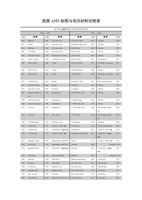
5640 AM-350 sheet
5548
5544 Waspaloy sheet
5754 Hastelloy X bar
303 Se Cond.A bar
5641 AM-355 bar
5743
5545 René 41 sheet
5759 L-605 bar
303 Se Cond. B bar
5738 AM-355 bar
5650 H-11 bar
6485
5651 H-11 vacuum melt bar
6487
5648 K500 bar
4676
5653 L-605 bar
5759
5645 L-605 sheet
5537
5510 M-50 bar
6490
5716 N-155 sheet
5532
5592 R405 bar
bar
4978 4340 bar
6415
4967 6Al/4V Ti bar
5664 718 bar
7Al/4Mo Ti bar
4970 4340 Mod. vacuum melt 6417
bar
4970 7Al/4Mo Ti bar
5665 600 bar
8Al/1Mo/1V Ti bar
4972 4340 vacuum melt bar
17-7 PH sheet
bar
5528 9310 premium quality
6267
bar
5520 15-7Mo PH sheet 5525 A-286 sheet 5526 19-9 DL sheet 5528 17-7 PH sheet
美国标准ACI中文版汇总

文件编号DocumentNumber Date R/E/S Date Language 1ACI 1041971.01.01(R 1997) English2ACI 1172010.06.01(R 2015) English3ACI 117.1R2014.08.01English4ACI 117M ERTA2011.09.23English5ACI 117M2010.07.01(R 2015) English6ACI 121R2008.07.01English7ACI 122R2014.12.01English8ACI 131.1R2015.01.01English9ACI 132R2014.12.01English10ACI 201.1R2008.07.01English11ACI 201.2R2008.06.01English12ACI 207.1R2005.01.01(R 2012) English13ACI 207.2R2007.09.01English14ACI 207.3R1994.01.01(R 2008) English15ACI 207.4R2005.01.01(R 2012) English16ACI 207.5R2011.07.01English17ACI 209.1R2005.01.01English18ACI 209.2R ERTA2008.05.01English19ACI 209.2R ERTA2008.05.28English20ACI 209.2R2008.05.01English21ACI 209R1992.01.01(R 2008) English22ACI 210R1993.01.01(R 2008) English23ACI 211.11991.01.01(R 2009) English24ACI 211.21998.01.01(R 2004) English25ACI 211.3R2002.01.01(R 2009) English26ACI 211.4R2008.12.01English27ACI 211.5R2014.04.01English28ACI 211.6T2014.12.01English29ACI 211.7R2015.05.01English30ACI 211.8R2015.06.01English31ACI 212.3R2010.11.01English32ACI 213R2014.06.01English33ACI 214.4R2010.06.01English 34ACI 214R2011.04.01English 35ACI 215R1992.01.01(R 1997) English36ACI 216.12014.11.01English37ACI 216.1M2007.01.01English 38ACI 221.1R1998.01.01(R 2008) English 39ACI 221R1996.01.01(R 2001) English 40ACI 222.2R2014.10.01English 41ACI 222.3R2011.04.01English 42ACI 222R2001.01.01(R 2010) English 43ACI 223R2010.12.01English 44ACI 224.1R2007.03.01English 45ACI 224.2R1992.01.01(R 2004) English 46ACI 224.3R ERTA2008.01.31English 47ACI 224.3R1995.01.01(R 2013) English 48ACI 224.4R2013.12.01English 49ACI 224R ERTA2008.03.24English 50ACI 224R2001.01.01English 51ACI 225R1999.01.01(R 2009) English 52ACI 228.1R2003.11.01English 53ACI 228.2R2013.06.01English 54ACI 229R2013.06.01English 55ACI 230.1R2009.07.01English 56ACI 231R2010.01.01English57ACI 232.1R2012.07.01English 58ACI 232.2R2003.01.01English 59ACI 232.3R2014.10.01English 60ACI 233R2003.01.01(R 2011) English 61ACI 234R2006.01.01English 62ACI 237R2007.04.01English 63ACI 238.1R2008.02.01English 64ACI 238.2T2014.06.01English 65ACI 3012010.01.01English 66ACI 301 SPANISH2010.01.01Spanish 67ACI 301M2010.01.01English 68ACI 302.1R2015.06.01English 69ACI 302.2R2006.01.01English 70ACI 303.11997.01.01English71ACI 303R2012.06.01English 72ACI 304.2R1996.01.01(R 2008) English 73ACI 304.3R1996.01.01(R 2004) English 74ACI 304.4R1995.01.01(R 2008) English 75ACI 304.6R2009.03.01English76ACI 304R2000.01.01(R 2009) English 77ACI 305.12014.08.01English 78ACI 305R2010.10.01English 79ACI 306.11990.01.01(R 2002) English 80ACI 306R2010.10.01English81ACI 307 ERTA2013.01.21English 82ACI 307 ERTA2010.06.04English 83ACI 3072008.11.01English 84ACI 308.12011.07.01English 85ACI 308.1M2011.07.01English 86ACI 308-213R2013.06.01English 87ACI 308R2001.01.01(R 2008) English 88ACI 309.1R2008.08.01English 89ACI 309.2R2015.02.01English 90ACI 309.5R2000.01.01(R 2006) English 91ACI 309R2005.01.01English 92ACI 310R2013.12.01English 93ACI 311.4R2005.01.01English 94ACI 311.52004.01.01English 95ACI 311.62009.11.01English 96ACI 311.6M2009.12.01English 97ACI 311.72014.06.01English98ACI 3131997.01.07English 99ACI 314R2011.01.01English 100ACI 3182014.09.01English 101ACI 318 CD2011.01.01English 102ACI 318M2014.01.01English103ACI 318SUS2014.01.01Spanish 104ACI 325.9R2015.08.01English 105ACI 325.11R2001.01.01English 106ACI 325.12R2002.01.01(R 2013) English107ACI 325.13R2006.01.01English 108ACI 327R2014.01.01English 109ACI 329R2014.12.01English 110ACI 330.12014.11.01English111ACI 330.1M2014.01.01English112ACI 330R2008.06.01English113ACI 3322014.02.01English 114ACI 332.1R ERTA2006.12.19English 115ACI 332.1R2006.12.01English 116ACI 332M2010.08.01English 117ACI 334.1R1992.01.01(R 2002) English 118ACI 334.3R2005.01.01English 119ACI 336.12001.01.01English 120ACI 336.2R1988.01.01(R 2002) English 121ACI 336.3R2014.08.01English 122ACI 341.2R2014.06.01English123ACI 341.3R2007.03.01English124ACI 343.1R2012.11.01English125ACI 343R1995.01.01(R 2004) English 126ACI 345.1R2006.01.01English 127ACI 345.2R2013.07.01English 128ACI 345R2011.09.01English 129ACI 3462009.08.01English 130ACI 346M2009.08.01English131ACI 347.2R2005.01.01English 132ACI 347.3R2013.01.01English 133ACI 347R2014.07.01English134ACI 3492013.01.01English 135ACI 349.1R2007.06.01English 136ACI 349.2R ERTA2007.11.12English 137ACI 349.2R2007.11.01(R 2014) English 138ACI 349.3R2002.01.01(R 2010) English 139ACI 349M2013.02.27English 140ACI 3502006.01.01English141ACI 350.12010.01.01English 142ACI 350.1M2010.01.01English 143ACI 350.2R ERTA2009.07.23English 144ACI 350.2R2004.01.01English 145ACI 350.3 ERTA2008.11.10English 146ACI 350.32006.01.01English 147ACI 350.4R2004.01.01English 148ACI 350.52012.01.01English 149ACI 350.5M2012.01.01English 150ACI 350M2006.01.01English 151ACI 351.1R2012.03.01English 152ACI 351.2R2010.04.01English 153ACI 351.3R2004.01.01(R 2011) English 154ACI 351.42014.01.01English 155ACI 351.52015.05.01English 156ACI 351.5M2015.09.01English 157ACI 352.1R2011.01.01English 158ACI 352R2002.01.01(R 2010) English 159ACI 352RS2002.01.01Spanish 160ACI 355.22007.06.01English 161ACI 355.3R2011.05.01English 162ACI 355.42011.08.01English 163ACI 355.4M2011.09.01English 164ACI 357.2R2010.07.01English 165ACI 357.3R2014.10.01English 166ACI 357R1984.01.01(R 1997) English 167ACI 360R2010.04.01English 168ACI 362.1R2012.09.01English 169ACI 362.2R2000.06.01(R 2013) English 170ACI 363.2R2011.07.01English171ACI 363R2010.03.01English 172ACI 364.1R2007.05.01English 173ACI 364.3R2009.04.01English 174ACI 364.2T2008.01.01English 175ACI 364.3T2015.01.01English 176ACI 364.4T2010.01.01English 177ACI 364.5T2010.01.01English 178ACI 364.6T2002.07.01(R 2011) English 179ACI 364.7T2002.04.01(R 2011) English 180ACI 364.8T2002.05.01(R 2011) English 181ACI 364.9T2003.07.01(R 2011) English 182ACI 364.10T2014.07.01English 183ACI 364.11T2015.08.01English 184ACI 364.12T2015.10.01English 185ACI 364.13T2015.10.01English 186ACI 365.1R2000.01.01English 187ACI 369R2011.02.01English 188ACI 370R2014.07.01English 189ACI 371R2008.08.01English 190ACI 372R2013.12.01English 191ACI 374.12005.01.01(R 2014) English 192ACI 374.2R2013.08.01English 193ACI 3762011.01.01English194ACI 376M2011.01.01English 195ACI 408.2R2012.09.01English 196ACI 408.3R2009.10.01English 197ACI 408R2003.11.01English 198ACI 421.1R2008.06.01English199ACI 421.2R2010.04.01English 200ACI 421.3R2015.10.01English 201ACI 423.3R2005.01.01English 202ACI 423.4R2014.11.01English 203ACI 423.72014.11.01English 204ACI 423.8R2010.10.01English205ACI 423.9M2010.06.01English206ACI 435.8R1985.01.01(R 1997) English207ACI 435R1995.01.01(R 2000) English208ACI 4372012.08.01English209ACI 437.1R2007.03.01English210ACI 437.22013.01.01English211ACI 437.2M2013.01.01English 212ACI 437R2003.01.01English 213ACI 439.3R2007.03.01English 214ACI 439.4R2009.10.01English215ACI 440.1R2015.03.01English 216ACI 440.2R2008.07.01English 217ACI 440.3R2012.08.01English218ACI 440.4R2004.12.01(R 2011) English 219ACI 440.52008.07.01English 220ACI 440.5M2008.07.01English 221ACI 440.62008.07.01English 222ACI 440.6M2008.07.01English 223ACI 440.7R2010.04.01English 224ACI 440.82013.01.01English 225ACI 440.8M2013.01.01English226ACI 440.9R2015.05.01English227ACI 440R2007.09.01English 228ACI 441R1996.01.01English 229ACI 445.1R2012.01.01English 230ACI 445R1999.01.01(R 2009) English 231ACI 446.1R1991.01.01(R 1999) English232ACI 446.3R1997.01.01English 233ACI 446.4R2004.01.01English 234ACI 503.2-503.4English 235ACI 503.32010.10.01English 236ACI 503.3M2010.10.01English 237ACI 503.5R1992.01.01(R 1997) (R 2003) English 238ACI 503.72007.09.01English 239ACI 506.1R2008.11.01English 240ACI 506.22013.01.01English 241ACI 506.2M2013.01.01English 242ACI 506.4R1994.01.01(R 2004) English 243ACI 506.5R2009.08.01English 244ACI 506R2005.01.01English 245ACI 515.2R2013.07.01English 246ACI 522.12013.06.01English 247ACI 522.1M2013.10.01English 248ACI 522R2010.03.01English 249ACI 523.1R2006.01.01English 250ACI 523.2R1996.01.01English 251ACI 523.3R2014.04.01English 252ACI 523.4R2009.06.01English 253ACI 524R2008.08.01English 254ACI 530/530.12013.09.13English255ACI 533.1R2002.09.01English 256ACI 533R2011.01.01English 257ACI 543R2012.03.01English 258ACI 544.1R1996.01.01(R 2009) English 259ACI 544.2R1989.01.01(R 2009) English 260ACI 544.3R2008.11.01English 261ACI 544.4R1988.01.01(R 2009) English 262ACI 544.5R2010.03.01English 263ACI 544.6R2015.09.01English264ACI 546.2R2010.06.01English265ACI 546.3R2014.06.01English266ACI 546R2014.09.01English 267ACI 548.1R2009.03.01English 268ACI 548.3R2009.04.01English 269ACI 548.42011.01.01English 270ACI 548.4M2011.01.01English 271ACI 548.5R1994.01.01(R 1998) English272ACI 548.6R1996.01.01English 273ACI 548.82007.10.01English 274ACI 548.8M2007.10.01English 275ACI 548.92008.08.01English 276ACI 548.9M2008.08.01English 277ACI 548.102010.08.01English 278ACI 548.10M2010.09.01English 279ACI 548.11R2012.09.01English 280ACI 548.122012.01.01English 281ACI 548.132014.10.01English 282ACI 548.142014.01.01English 283ACI 548.14M2014.01.01English 284ACI 549.1R1993.01.01(R 2009) English 285ACI 549.2R2004.05.01(R 2013) English 286ACI 549.3R2009.12.01English 287ACI 549.4R2013.12.01English 288ACI 549R1997.01.24(R 2009) English 289ACI 550.1R2009.02.01English 290ACI 550.2R2013.04.01English 291ACI 550.32013.11.01English292ACI 550.3M2013.01.01English 293ACI 551.1R2014.11.01English 294ACI 551.2R2015.08.01English 295ACI 555R2001.01.01English296ACI 5622013.03.01English297ACI 562M2013.05.01English 298ACI ASCC-12005.01.01English 299ACI ASCC-1 SPANISH2005.01.01Spanish 300ACI C-071986.01.01English 301ACI C-081987.01.01English 302ACI CCS-01993.11.01English 303ACI CCS-12010.01.01English 304ACI CCS-31989.01.01English 305ACI CCS-42008.01.01English 306ACI CFPR1998.01.01English 307ACI CP-602009.01.01English308ACI CR MANUAL2013.01.01English 309ACI CT01 CD1998.01.01English 310ACI DCCM2011.01.01English 311ACI E12007.01.01English 312ACI E22000.01.01English 313ACI E42012.01.01English 314ACI EB0711991.01.01English 315ACI IJBRC2006.01.01English 316ACI IPS-12002.01.01English317ACI ITG-32004.01.01English 318ACI ITG-4.12007.03.01English 319ACI ITG-4.2R2006.10.01English 320ACI ITG-4.3R2007.09.01English321ACI ITG-5.12007.01.01English 322ACI ITG-5.1M2007.01.01English 323ACI ITG-5.22009.08.01English324ACI ITG-6R2010.08.01English 325ACI ITG-72009.11.01English 326ACI ITG-7M2009.11.01English 327ACI ITG-8R2010.12.01English 328ACI LICC2004.01.01English329ACI MCP-12014.01.01English330ACI MCP-22014.01.01English331ACI MCP-32014.01.01English332ACI MCP-42014.01.01English333ACI MCP-52014.01.01English334ACI MCP-62014.01.01English335ACI MCP-72014.01.01English 336ACI MCP COMBO2014.01.01English 337ACI MCP SET2015.01.01English 338ACI MCP SET CD2014.01.01English 339ACI MDG2013.01.01English 340ACI MSP2009.01.01English 341ACI NGBSPACK2008.01.01English 342ACI PCP2004.01.01English 343ACI PRCD.EM2014.01.01English 344ACI PTM2006.01.01English 345ACI RPMN13PACK2013.01.01English346ACI SCG12010.01.01EnglishTitle StatusPreparation of Notation for Concrete Active Specification for Tolerances for Concrete Construction andActive Materials (ACI 117-10) and Commentary (ACI 117R-10)Guide for Tolerance Compatibility in Concrete Construction ActiveSpecification for Tolerances for Concrete Construction andActive Materials (ACI 117M-10) and CommentarySpecification for Tolerances for Concrete Construction andActive Materials (ACI 117M-10) and Commentary (ACI 117RM-10)Guide for Concrete Construction Quality Systems inActive Conformance with ISO 9001Guide to Thermal Properties of Concrete and MasonryActive SystemsInformation Delivery Manual (IDM) for Cast-in-PlaceActive ConcreteGuide for Responsibility in Concrete Construction ActiveGuide for Conducting a Visual Inspection of Concrete inActive ServiceGuide to Durable Concrete Active Guide to Mass Concrete ActiveReport on Thermal and Volume Change Effects on Cracking ofActive Mass ConcretePractices for Evaluation of Concrete in Existing MassiveActive Structures for Service ConditionsCooling and Insulating Systems for Mass Concrete Active Report on Roller-Compacted Mass Concrete ActiveReport on Factors Affecting Shrinkage and Creep ofActive Hardened ConcreteGuide for Modeling and Calculating Shrinkage and Creep inActive Hardened ConcreteGuide for Modeling and Calculating Shrinkage and Creep inActive Hardened ConcreteGuide for Modeling and Calculating Shrinkage and Creep inActive Hardened ConcretePrediction of Creep, Shrinkage, and Temperature Effects inActive Concrete StructuresErosion of Concrete in Hydraulic Structures ActiveStandard Practice for Selecting Proportions for Normal,Active Heavyweight, and Mass ConcreteStandard Practice for Selecting Proportions for StructuralActive Lightweight ConcreteGuide for Selecting Proportions for No-Slump Concrete ActiveGuide for Selecting Proportions for High-Strength ConcreteActive Using Portland Cement and Other Cementitious MaterialsGuide for Submittal of Concrete Proportions Active Aggregate Suspension Mixture Proportioning Method ActiveGuide for Proportioning Concrete Mixtures with GroundActive Limestone and Other Mineral FillersGuide to Troubleshooting Concrete Mixture Issues asActive Influenced by Constitutive Materials, Jobsite Conditions,or Testing PracticesReport on Chemical Admixtures for Concrete Active Guide for Structural Lightweight-Aggregate Concrete ActiveGuide for Obtaining Cores and Interpreting CompressiveActive Strength ResultsGuide to Evaluation of Strength Test Results of Concrete ActiveConsiderations for Design of Concrete Structures SubjectedActive to Fatigue LoadingCode Requirements for Determining Fire Resistance ofActive Concrete and Masonry Construction AssembliesCode Requirements for Determining Fire Resistance ofActive Concrete and Masonry Construction AssembliesReport on Alkali-Aggregate Reactivity ActiveGuide for Use of Normal Weight and Heavyweight AggregatesActive in ConcreteReport on Corrosion of Prestressing Steels ActiveGuide to Design and Construction Practices to MitigateActive Corrosion of Reinforcement in Concrete StructuresProtection of Metals in Concrete Against Corrosion Active Guide for the Use of Shrinkage-Compensating Concrete ActiveCauses, Evaluation, and Repair of Cracks in ConcreteActive StructuresCracking of Concrete Members in Direct Tension Active Joints in Concrete Construction Active Joints in Concrete Construction Active Guide to Design Detailing to Mitigate Cracking Active Control of Cracking in Concrete Structures Active Control of Cracking in Concrete Structures Active Guide to the Selection and Use of Hydraulic Cements Active In-Place Methods to Estimate Concrete Strength ActiveReport on Nondestructive Test Methods for Evaluation ofActive Concrete in StructuresReport on Controlled Low-Strength Materials Active Report on Soil Cement ActiveReport on Early-Age Cracking: Causes, Measurement, andActive MitigationReport on the Use of Raw or Processed Natural Pozzolans inActive ConcreteUse of Fly Ash in Concrete ActiveReport on High-Volume Fly Ash Concrete for StructuralActive ApplicationsSlag Cement in Concrete and Mortar Active Guide for the Use of Silica Fume in Concrete Active Self-Consolidating Concrete ActiveReport on Measurements of Workability and Rheology ofActive Fresh ConcreteConcrete Thixotropy ActiveSpecifications for Structural Concrete - IncorporatingActive Errata: 23, February 2015Especificaciones para Concreto Estructural ActiveSpecifications for Structural Concrete - IncorporatingActive Errata: 23, February 2015Guide to Concrete Floor and Slab Construction ActiveGuide for Concrete Slabs that Receive Moisture-SensitiveActive Flooring MaterialsStandard Specification for Cast-In-Place ArchitecturalActive ConcreteGuide to Cast-in-Place Architectural Concrete Practice ActivePlacing Concrete by Pumping Methods Active Heavyweight Concrete: Measuring, Mixing, Transporting, andActive PlacingPlacing Concrete with Belt Conveyors ActiveGuide for Use of Volumetric-Measuring and Continuous-Active Mixing Concrete EquipmentGuide for Measuring, Mixing, Transporting, and PlacingActive ConcreteSpecification for Hot Weather Concreting Active Guide to Hot Weather Concreting Active Standard Specification for Cold Weather Concreting Active Guide to Cold Weather Concreting ActiveCode Requirements for Reinforced Concrete Chimneys (ACIActive 307-08) and CommentaryCode Requirements for Reinforced Concrete Chimneys andActive CommentaryCode Requirements for Reinforced Concrete Chimneys (ACIActive 307-08) and CommentarySpecification for Curing Concrete Active Specification for Curing Concrete ActiveReport on Internally Cured Concrete Using PrewettedActive Absorptive Lightweight AggregateGuide to Curing Concrete Active Report on Behavior of Fresh Concrete During Vibration ActiveGuide to Identification and Control of Visible SurfaceActive Effects of Consolidation on Formed Concrete SurfacesCompaction of Roller-Compacted Concrete Active Guide for Consolidation of Concrete Active Guide to Decorative Concrete Active Guide for Concrete Inspection ActiveGuide for Concrete Plant Inspection and Testing of Ready-Active Mixed ConcreteSpecification for Ready Mixed Concrete Testing Services Active Specification for Ready Mixed Concrete Testing Services ActiveInspection Services Specification for Cast-in-PlaceActive Concrete ConstructionStandard Practice for Design and Construction of ConcreteActive Silos and Stacking Tubes for Storing Granular MaterialsGuide to Simplified Design for Reinforced ConcreteActive BuildingsBuilding Code Requirements for Structural Concrete andActive Commentary - Incorporated Errata: October 9, 2015Building Code Requirements for Structural Concrete andActive Commentary - CD ROM: To Purchase Call 1-800-854-7179USA/Canada or 303-397-7956 WorldwideBuilding Code Requirements for Structural Concrete (ACIActive 318M-14) and Commentary (ACI 318RM-14)Building Code Requirements for Structural Concrete andActive Commentary-Spanish Inch-PoundGuide for Construction of Concrete Pavements Active Accelerated Techniques for Concrete Paving ActiveGuide for Design of Jointed Concrete Pavements for StreetsActive and Local RoadsConcrete Overlays for Pavement Rehabilitation ActiveGuide to Roller- Compacted Concrete Pavements Active Report on Performance-Based Requirements for Concrete Active Specification for Unreinforced Concrete Parking Lots andActive Site PavingSpecification for Unreinforced Concrete Parking Lots andActive Site PavingGuide for the Design and Construction of Concrete ParkingActive LotsResidential Code Requirements for Structural Concrete (ACIActive 332-10) and CommentaryGuide to Residential Concrete Construction Active Guide to Residential Concrete Construction ActiveResidential Code Requirements for Structural Concrete (ACIActive 332M-10) and CommentaryConcrete Shell Structures Practice and Commentary Active Construction of Concrete Shells Using Inflated Forms Active Specification for the Construction of Drilled Piers ActiveSuggested Analysis and Design Procedures for CombinedActive Footings and MatsReport on Design and Construction of Drilled Piers ActiveReport on Analysis and Design of Seismic-ResistantActive Concrete Bridge SystemsSeismic Evaluation and Retrofit Techniques for ConcreteActive BridgesGuide for the Analysis and Design of Reinforced andActive Prestressed Concrete Guideway StructuresAnalysis and Design of Reinforced Concrete BridgeActive StructuresGuide for Maintenance of Concrete Bridge Members Active Guide for Widening Highway Bridges Active Guide for Concrete Highway Bridge Deck Construction Active Specification for Cast-in-Place Concrete Pipe Active Specification for Cast-in-Place Concrete Pipe ActiveGuide for Shoring/Reshoring of Concrete MultisoryActive BuildingsGuide to Formed Concrete Surfaces Active Guide to Formwork for Concrete Active Code Requirements for Nuclear Safety-Related ConcreteActive Structures (ACI 349-13) and Commentary - IncorporatingErrata: 23, February 2015Reinforced Concrete Design for Thermal Effects on NuclearActive Power Plant StructuresConcrete Capacity Design (CCD) Method-Embedment DesignActive ExamplesGuide to the Concrete Capacity Design (CCD) Method -Active Embedment Design ExamplesEvaluation of Existing Nuclear Safety-Related ConcreteActive StructuresCode Requirements for Nuclear Safety-Related ConcreteActive Structures (ACI 349M-06) and Commentary - IncorporatesErrata: 2/24/2015Code Requirements for Environmental Engineering ConcreteActive Structures and Commentary - Incorporates Errata: 10/09/15Specification for Tightness Testing of EnvironmentalActive Engineering Concrete Containment Structures (ACI 350.1-10)and CommentarySpecification for Tightness Testing of EnvironmentalEngineering Concrete Containment Structures (ACI 350.1M-Active 10) and CommentaryConcrete Structures for Containment of Hazardous Materials Active Concrete Structures for Containment of Hazardous Materials ActiveSeismic Design of Liquid-Containing Concrete StructuresActive and CommentarySeismic Design of Liquid-Containing Concrete StructuresActive and CommentaryDesign Considerations for Environmental EngineeringActive Concrete StructuresSpecifications for Environmental Concrete Structures Active Specifications for Environmental Concrete Structures Active CODE REQUIREMENTS FOR ENVIRONMENTAL ENGINEERING CONCRETE STRUCTURES (ACI 350M-06) AND COMMENTARY - IncorporatingActive Errata: 4/29/2015Report on Grouting between Foundations and Bases forActive Support of Equipment and MachineryReport on Foundations for Static Equipment Active Foundations for Dynamic Equipment ActiveSpecification for Installation of Cementitious GroutingActive between Foundations and Equipment BasesSpecification for Installation of Epoxy Grout betweenActive Foundations and Equipment BasesSpecification for Installation of Epoxy Grout betweenActive Foundations and Equipment BasesGuide for Design of Slab-Column Connections in MonolithicActive Concrete StructuresRecommendations for Design of Beam-Column Connections inActive Monolithic Reinforced Concrete StructuresRecomendaciones para el Dise?o de Conexiones Viga-ColumnaActive en Estructuras Monolíticas de Concreto ReforzadoQualification of Post-Installed Mechanical Anchors inActive Concrete and CommentaryGuide for Design of Anchorage to Concrete: Examples UsingActive ACI 318 Appendix DQualification of Post-Installed Adhesive Anchors inActive Concrete (ACI 355.4) and CommentaryQualification of Post-Installed Adhesive Anchors inActive Concrete (ACI 355.4M-11) and CommentaryReport on Barge-Like Concrete Structures ActiveGuide for Design and Construction of Waterfront andActive Coastal Concrete Marine StructuresGuide for the Design and Construction of Fixed OffshoreActive Concrete StructuresGuide to Design of Slabs-on-Ground ActiveGuide for the Design and Construction of Durable ConcreteActive Parking StructuresGuide for Structural Maintenance of Parking Structures ActiveGuide to Quality Control and Assurance of High-StrengthActive ConcreteReport on High-Strength Concrete ActiveGuide for Evaluation of Concrete Structures Prior toActive RehabilitationGuide for Cementitious Repair Material Data Sheet ActiveIncreasing Shear Capacity Within Existing ReinforcedActive Concrete StructuresTreatment of Exposed Epoxy-Coated Reinforcement in Repair ActiveDetermining the Load Capacity of a Structure When As-BuiltActive Drawings are UnavailableImportance of Modulus of Elasticity in Surface RepairActive MaterialsConcrete Removal in Repairs Involving Corroded ReinforcingActive SteelEvaluation and Minimization of Bruising (Microcracking) inActive Concrete RepairUse of Hydrodemolition for Concrete Removal in UnbondedActive Post-Tensioned SystemsCracks in a Repair ActiveRehabilitation of Structure with Reinforcement SectionActive LossManaging Alkali-Aggregate Reaction Expansion in MassActive ConcreteRepair of Leaking Cracks in Walls of Liquid ContainmentActive StructuresRepairs for Reinforcement with Shallow Cover Active Service-Life Prediction - State-of-the-Art Report ActiveGuide for Seismic Rehabilitation of Existing ConcreteActive Frame Buildings and CommentaryReport for the Design of Concrete Structures for BlastActive EffectsGuide for the Analysis, Design, and Construction ofElevated Concrete and Composite Steel-Concrete WaterActive Storage TanksGuide to Design and Construction of Circular Wire- andActive Strand-Wrapped Prestressed Concrete StructuresAcceptance Criteria for Moment Frames Based on StructuralActive Testing and CommentaryGuide for Testing Reinforced Concrete Structural ElementsActive under Slowly Applied Simulated Seismic LoadsCode Requirements for Design and Construction of ConcreteActive Structures for the Containment of Refrigerated LiquefiedGases and CommentaryCode Requirements for Design and Construction of ConcreteActive Structures for the Containment of Refrigerated LiquefiedGases and CommentaryReport on Bond of Steel Reinforcing Bars Under CyclicActive LoadsGuide for Lap Splice and Development Length of HighActive Relative Rib Area Reinforcing Bars in Tension andCommentaryBond and Development of Straight Reinforcing Bars inActive TensionGuide to Shear Reinforcement for Slabs - IncorporatingActive Errata : 02/23/2015Guide to Seismic Design of Punching Shear Reinforcement inActive Flat PlatesGuide to Design of Reinforced Two-Way Slab Systems ActiveRecommendations for Concrete Members Prestressed withActive Unbonded TendonsCorrosion and Repair of Unbonded Single Strand Tendons Active Specification for Unbonded Single-Strand Tendon Materials ActiveReport on Corrosion and Repair of Grouted Multistrand andActive Bar Tendon SystemsTest Method for Bleed Stability of Cementitious Post-Active Tensioning Tendon GroutObserved Deflections of Reinforced Concrete Slab Systems,Active and Causes of Large DeflectionsControl of Deflection in Concrete Structures -Active incorporates Appendix B: 2003Code Requirements For Load Testing Of Existing ConcreteActive Structures And CommentaryLoad Tests of Concrete Structures: Methods, Magnitude,Active Protocols, and Acceptance CriteriaCode Requirements for Load Testing of Existing ConcreteActive Structures (ACI 437.2-13) and CommentaryCode Requirements for Load Testing of Existing ConcreteActive Structures (ACI 437.2M-13) and CommentaryStrength Evaluation of Existing Concrete Buildings Active Types of Mechanical Splices for Reinforcing Bars ActiveReport on Steel Reinforcement-Material Properties and U.S.Active AvailabilityGuide for the Design and Construction of StructuralActive Concrete Reinforced with Fiber-Reinforced Polymer (FRP)BarsGuide for the Design and Construction of Externally BondedFRP Systems for Strengthening Concrete Structures -Active Incorporating Errata : 02/27/2015Guide Test Methods for Fiber-Reinforced Polymer (FRP) Composites for Reinforcing or Strengthening Concrete andActive Masonry StructuresPrestressing Concrete Structures with FRP Tendons ActiveSpecification for Construction with Fiber-ReinforcedActive Polymer Reinforcing BarsSpecification for Construction with Fiber-ReinforcedActive Polymer Reinforcing BarsSpecification for Carbon and Glass Fiber-ReinforcedActive Polymer Bar Materials for Concrete ReinforcementSpecification for Carbon and Glass Fiber-ReinforcedActive Polymer Bar Materials for Concrete ReinforcementGuide for the Design and Construction of Externally BondedActive Fiber-Reinforced Polymer Systems for StrengtheningUnreinforced Masonry StructuresSpecification for Carbon and Glass Fiber-ReinforcedActive Polymer (FRP) Materials Made by Wet Layup for External Strengthening of Concrete and Masonry StructuresSpecification for Carbon and Glass Fiber-ReinforcedPolymer (FRP) Materials Made by Wet Layup for ExternalActive Strengthening of Concrete and Masonry Structures。
- 1、下载文档前请自行甄别文档内容的完整性,平台不提供额外的编辑、内容补充、找答案等附加服务。
- 2、"仅部分预览"的文档,不可在线预览部分如存在完整性等问题,可反馈申请退款(可完整预览的文档不适用该条件!)。
- 3、如文档侵犯您的权益,请联系客服反馈,我们会尽快为您处理(人工客服工作时间:9:00-18:30)。
Chloride Penetration Resistance of a Ternary BlendLightweight Concrete Bridge DeckRyan Ankabrandt 1and Edwin Burdette,F.ASCE 2Abstract:In 2010,the Tennessee Department of Transportation (TDOT)launched a bridge rehabilitation project to rerate all truss bridges with gusset plate connections due to the federal mandate after the Minneapolis bridge collapse in 2005.One bridge that needed to be renovated was the Hurricane Bridge in Dekalb County,Tennessee.To provide a durable bridge deck and meet the latest highway loading specifications,TDOT used a Class L ternary (sand-lightweight ternary)mix instead of their standard Class D (normal weight nonternary)bridge deck mix.While placing a section of the deck,TDOT would cast cylinders to send to the University of Tennessee for rapid chloride penetration (RCP),surface resistivity (SR),and compressive strength testing.Previous RCP and SR testing of the TDOT Class D mix found that the mix provides poor to moderate chloride ion penetration resistance.Research reported herein supports the use of the TDOT Class L ternary mix as an alternative to the TDOT Class D mix in order to increase bridge deck durability.The results of the Class L ternary mix cylinder testing show a decrease in chloride ion penetration,an increase in surface resistivity,higher compressive strengths,and a higher correlation between SR and RCP than Class D cylinders.DOI:10.1061/(ASCE)CF.1943-5509.0000504.©2014American Society of Civil Engineers.Author keywords:Ternary blend;Durability;Bridge deck;Surface resistivity;Chloride ion penetration.IntroductionThe Tennessee Department of Transportation (TDOT)regularly uses a Class D normal weight (NW)concrete mix for highway and inter-state bridge decks throughout the state.For proportioning and qual-ity assurance,the mix requires 27.6MPa (4,000psi)minimum 28-day compressive strength,368kg =m 3(620lbs =yd 3)of cementi-tious material,0.40maximum water-to-cement ratio,6.0–8.5%air (for pumpability),and a 203.2-mm (8-in.)maximum slump [76.2-mm (3-in.)maximum before addition of high-range water-reducing admixture (HRWRA)](TDOT 2006).During the past decade,a study has been ongoing at the Uni-versity of Tennessee (UT)dealing with the durability of the Class D mix.The emphasis of the study was to determine the resistance to chloride ion penetration of the mix using the surface resistivity (SR)test and the rapid chloride penetration (RCP)test.For the past 3years,UT has been performing SR and RCP tests on Class D mix cylinders from various bridge deck placements across Tennes-see.From the studies performed at UT,the majority of Class D mix bridge decks were found to be,at best,mediocre in terms of resisting the penetration of chloride ions into the concrete.Despite there being no requirements on the use of mineral admixtures in the Class D mix,most of the mixes were found to contain 100%port-land cement or,more commonly,portland cement with a relatively small amount of Class F fly ash.While work done by UT both in the laboratory and in cooperation with a local ready-mix supplier showed clearly that the use of a ternary blend mixture containing cement,fly ash,and ground granulated blast furnace slag (GGBFS)(herein referred to as slag cement)was better in terms of resistance to chloride ions,TDOT has never implemented such a mixture on an entire bridge deck.Recently,the need for a high-performance lightweight concrete (HPLWC)bridge deck arose with TDOT ’s rehabilitation of the Hurricane Bridge.To ensure greater durability with lower chloride ion penetration,TDOT decided that the Hurricane Bridge deck would consist of a lightweight (LW)ternary mix incorporating portland cement,fly ash,and slag cement (TDOT 2010)instead of the typical 100%portland cement or binary Class D mix.This decision led to the work presented in this paper.Hurricane BridgeIn the fall of 1947,the construction of the Hurricane Bridge started as a means to carry relocated State Route 56over the Caney Fork River in northern Dekalb County,Tennessee,in order to accommo-date the closure of the newly constructed Center Hill Dam and subsequent impoundment of the river.Two years later construction of the bridge was finished and the bridge opened to traffic (Fig.1).Designed by the Nashville District of the U.S.Army Corps of Engineers,the 544.4-m (1,786-ft)–long Hurricane Bridge resided 82.9m (272ft)above the river bed and consisted of two 235.0-m (771-ft)–long continuous Warren deck trusses spaced 7.3m (24ft)on centers and a 18.6-m (61-ft)two-span deck girder unit at each approach (Wasserman 2012).In 1977,the bridge was modified from the original 7.3-m (24-ft)roadway and 457.2-mm (18-in.)safety curbs to a 13.4-m (44-ft)–wide deck to provide improved sight distance near the entrance to the newly constructed Edgar Evins Appalachian Craft Center.Widening was accomplished with the addition of cantilevers to the truss floor beams to support two new lines of stringers and two new lines of beams to the approach spans.Analysis of the modified system determined that the bridge could accommodate AASHTO HS-20(AASHTO 1973)loading at operating levels and HS-15(AASHTO 1973)loading at the inventory level,which was consid-ered satisfactory considering the low density of commercial traffic1Graduate Research Assistant,Dept.of Civil Engineering,Univ.of Tennessee,92Dune Lakes Circle,Santa Rosa Beach,FL 32459.2Fred N.Peebles Professor of Civil Engineering,Univ.of Tennessee,913Tampa Rd.,Knoxville,TN 37923(corresponding author).E-mail:eburdett@Note.This manuscript was submitted on March 5,2013;approved on July 29,2013;published online on July 31,2013.Discussion period open until October 20,2014;separate discussions must be submitted for indivi-dual papers.This paper is part of the Journal of Performance of Con-structed Facilities ,©ASCE,ISSN 0887-3828/04014011(7)/$25.00.D o w n l o a d e d f r o m a s c e l i b r a r y .o r g b y S h a n g h a i J i a o t o n g U n i v e r s i t y o n 08/04/14. C o p y r i g h t A S CE .F o r p e r s o n a l u s e o n l y ; a l l r i g h t s r e s e r v e d .on the route (Wasserman 2012).The concrete deck consisted of a TDOT Class A mix that requires a 20.7-MPa (3,000-psi)minimum 28-day compressive strength,334.6kg =m 3(564lbs =yd 3)of ce-mentitious material,0.45maximum water-to-cement ratio,6(Æ2)%air content,and 76.2Æ25.4mm (3Æ1in :)slump (TDOT 2006).In 2010,in light of the federal mandate to rerate all truss bridges with gusset plate connections due to the Minneapolis bridge col-lapse,TDOT launched a major bridge rehabilitation project on the Hurricane Bridge through TDOT ’s Better Bridges Program.Originally designed for the HS-15load,the bridge is being retro-fitted to accommodate HL-93(AASHTO 1973)loading.Retrofit work items include concrete repairs,sand blasting,repainting,and strengthening the substructure,selected compression diago-nals,floor beams,and stringers,as well as seismically strengthen-ing the bearings (Wasserman 2012).To decrease dead loads and increase durability,the new bridge deck will use a TDOT Class L ternary concrete mix,which has the same proportioning and quality assurance requirements as the Class D mix mentioned pre-viously.The Class L ternary mix is technically considered a sand-lightweight ternary mix according to the American Concrete Institute (ACI),meaning normal weight natural sand was used as the fine aggregate instead of lightweight fine aggregate.How-ever,because all bridge decks and tests being mentioned used sand-lightweight,for the remainder of the paper sand-lightweight will be referred to as simply lightweight (ACI Committee 318-2011).The cementitious material for the mix consists of 60%portland cement,20%Class C fly ash,and 20%Grade 100slag cement.Research SignificanceWhile there has been a fair amount of research done on improving concrete bridge deck durability,there have been no studies of whichthe authors of this paper are aware that were solely focused on the permeability of lightweight aggregate ternary concrete mixtures in bridge decks.The intent of using slag cement and Class C fly ash as partial replacement of portland cement for the lightweight aggre-gate concrete bridge deck was to reduce long-term repair costs by increasing the concrete durability.The study described herein not only supports the implementation of ternary lightweight concrete mixtures,but also addresses the correlation between the SR [AASHTO TP 95(2011)]and RCP [ASTM C1202(2010b )]test methods.Literature Review:Relevant TestingThis literature review focuses on research related to the durability of structural lightweight concrete.ACI defines structural light-weight concrete as structural concrete made with low-density ag-gregate that has an air-dry density of not more than 1;842.1kg =m 3(115lb =ft 3)and a 28-day compressive strength of more than 17.2MPa (2,500psi)(ACI 2000).Numerous bridges have incor-porated LW concrete in one aspect or another to reduce the struc-ture ’s dead loads and reduce transportation and structural costs.The use of LW concrete bridge decks can significantly reduce dead loads,which translates to longer spans,greater girder spacing,or the use of fewer girders.LW concrete can also lead to less main-tenance and longer life (Ozyildirim 2011).However,with LW con-crete there would appear to be a greater concern for durability from an increased rate of ingress of aggressive ions due to the porous nature of the LW aggregates.To a large extent durability is con-trolled by permeability.In order to increase the durability the per-meability must decrease,which depends on the type and amount of supplementary cementitious material (SCM),curing method,andFig.1.State Route 56Hurricane Bridge after completion (image courtesy of U.S.Army Corps of Engineers,Nashville,TN District)D o w n l o a d e d f r o m a s c e l i b r a r y .o r g b y S h a n g h a i J i a o t o n g U n i v e r s i t y o n 08/04/14. C o p y r i g h t A S CE .F o r p e r s o n a l u s e o n l y ; a l l r i g h t s r e s e r v e d .water to cementitious material ratio (w/cm)of the concrete mix (Ozyildirim 2009).Despite the porosity of LW aggregates,studies have shown that LW concrete has equal or less permeability compared to NW con-crete (Wall and Freeman 2003).This seeming anomaly is attributed to a combination of an improved interfacial transition zone,a more unified structure,and a reduction of internal stresses due to volume changes in the initial unloaded state.Throughout the United States,bridge decks are often subject to acidic chemicals through ocean saltwater or deicing salts (sodium chloride or simply NaCl)used to prevent and reduce ice forming on the deck surface during inclement weather.Shrinkage cracks and pores in the concrete provide access for harmful chemicals to pass through the concrete to the embedded reinforcement.Despite the normally high pH of the concrete,the passive layer around the reinforcing steel formed from the interaction of steel and concrete cannot resist the corrosive attack (ACI Committee 201-2008).Thus,SCMs are often introduced into the mix to enhance the ability of the slab to reduce the penetration of chloride ions through the concrete to the reinforcement.Mineral admixtures such as silica fume,fly ash,and slag cement are some common SCMs that have been proven to lower the permeability of LW concrete by rein-forcing the LW aggregate and the paste-aggregate interface (Wang 2005).In 2009,the Virginia Center for Transportation Innovation and Research (VCTIR),formerly the Virginia Transportation Research Council (VTRC),performed laboratory tests on high-performance lightweight (HPLW)concrete bridge beams and decks over the Manttaponi and Pamunkey rivers on Route 33in Virginia to evalu-ate various concrete properties with different curing conditions.For both bridge decks,a maximum penetration of 2,500coulombs and a 28-day compressive strength of 34.5MPa (5,000psi)were specified.The mixture proportions were the same for both bridge decks and consisted of 348.99kg =m 3[588pounds per cubic yard (pcy)]Type II cement,87.2kg =m 3(147pcy)Class F fly ash,563.6kg =m 3(950pcy)lightweight coarse aggregates,662.1kg =m 3(1,116pcy)normal weight natural sand,174.4kg =m 3(294pcy)water,and air-entraining,water-reducing,and water-retarding admixtures.The samples taken during each bridge casting were continuously moist cured until testing.The first and second batches from the Mattaponi Bridge deck had 28-day compressive strengths of 42.1MPa (6,110psi)and 43.5MPa (6,310psi),respectively,and 28-day permeabilities of 939and 976coulombs,respectively.The first and second batches from the Pamunkey Bridge had 28-day compressive strengths of 48.7MPa (7,060psi)and 41.6MPa (6,040psi),respectively,and 28-day permeabilities of 1,411and 1,940coulombs,respec-tively.Permeability values were all satisfactory and considered to be either low or very low (Ozyildirim 2009).In 2011,VCTIR did a similar study on HPLW concrete with LW aggregates from varying locations and subjected to different curing conditions while trying to determine if the SR test is a good indicator of permeability and could be used in lieu of the time-consuming RCP test.Both batches for the permeability study used LW aggregates from North Carolina,a w/cm ratio of 0.40,and 356kg =m 3(600pcy)of cementitious material.One batch used 30%fly ash and 70%portland cement for the cementitious material,and the other used 50%slag cement and 50%portland cement.Permeability was determined by the RCP test in accor-dance with Virginia Test Method 112(VTM 112)[Virginia Depart-ment of Transportation (VDOT)Materials Division 2007],which is based on the ASTM C1202standard (ASTM 2010b ).The VTM 112varies slightly from the 2010revision of the ASTM C1202in that it includes accelerated wet curing,which involves 1week at room temperature and 3weeks in a 37.8°C (100°F)water bath (Ozyildirim 2011).As shown in Table 1,the permeability improved with accelerated curing,and low permeability was obtained with the addition of fly ash or slag cement.Also in 2011,UT researchers tested two batches of TDOT field-cast Class L (lightweight binary)cylinders.The Class L mix used similar proportioning and quality assurance requirements as the Class D mix mentioned previously,but required a maximum water-to-cement ratio of 0.39instead of 0.40and used 25%Class C fly ash and 75%portland cement as cementitious materials.The compressive strength of the Class L cylinders exceeded TDOT ’s minimum 28-day strength of 27.6MPa (4,000psi)as expected,but the SR and RCP results were subpar.Both batches had 28-day RCP and SR values over 7,300coulombs and less than 9kOhm-cm,respectively,and 56-day RCP and SR values over 4,100coulombs and less than 12kOhm-cm,respectively,which are considered high chloride ion penetration values by Kessler et al.(2005)and extremely high values by UT researchers.In 2012,in addition to continued testing of TDOT 101.6×203.2mm (4×8in :)field-cast Class D cylinders,UT researchers performed SR [AASHTO TP-95(2011)]and RCP [ASTM C1202(2010b )]tests on UT laboratory-cast NW ternary cylinders and laboratory-cast LW binary and ternary cylinders.The LW binary (LWB)mix ’s cementitious material incorporated 25%Class F fly ash and 75%portland cement.The NW ternary (NWT)and LW ternary (LWT)mix ’s cementitious material was composed of 20%Class F fly ash,30%slag cement,and 50%portland ce-ment.All of the cylinders from the three mixes were cured in the same lime water bath.As shown in Table 2,the LWT mix out-performed the LWB and NWT mixes.According to the chloride ion penetration classification in Table 3,the binary mix had low pen-etrability and the two ternary mixes had very low penetrability.Surprisingly,the NWT and LWB mixes had relatively close 56-day SR values,but as expected the NWT mix had a lower 56-day RCP than the LWB mix,primarily because of the addition of slag cement.Other than the supplementary cementitious materials,the differences in aggregates used might account for any discrepancies in the results.Table 1.Virginia Penetrability Results (Data from Ozyildirim 2011)Curing conditionAge (days)Concrete with fly ashConcrete with Slag Cement RCP (coulombs)SR (kOhm-cm)RCP (coulombs)SR (kOhm-cm)Moist cure (MC)282,91215.141,35330.31MC 1wk 73°F +3wk 100°F 2829870.0161441.59MC 2wk 73°F +2wk 100°F 2854850.6268839.42MC 3wk 73°F +1wk 100°F 281,19025.7496030.29MC362,18718.80——D o w n l o a d e d f r o m a s c e l i b r a r y .o r g b y S h a n g h a i J i a o t o n g U n i v e r s i t y o n 08/04/14. C o p y r i g h t A S CE .F o r p e r s o n a l u s e o n l y ; a l l r i g h t s r e s e r v e d .Hurricane Bridge Deck EvaluationThe study reported in this paper focused primarily on the LW con-crete used on the Hurricane Bridge on State Route 56in Dekalb County,Tennessee,and the performance of that concrete in terms of resistance to chloride ion penetration.The LW aggregates used for the Hurricane Bridge and UT laboratory mixes mentioned pre-viously were 18-mm (3=4-in :)Stalite rotary kiln expanded slate from North Carolina (Stalite 2008,2011).Engineering index properties of Stalite ’s 18-mm (3=4-in :)LW stone can be found in Table 4.The weight saving by using this mix was approximately 20%at an additional cost of roughly 25to 40%above that for a typical Tennessee Class D mix.For the Hurricane Bridge renovation there was no required mini-mum SR value or maximum permeability value (RCP)for the con-crete bridge deck,but a general desire for moderate or better chloride ion penetration was expressed by TDOT.As noted previ-ously,tests of the Class D binary mix used throughout Tennessee for almost all bridge decks indicated mediocre (at best)resistance to chloride ion penetration.While the number of decks that utilized lightweight aggregate were few,those few tests also yielded medio-cre penetration resistance.Thus,the conclusion followed that a change was needed if the desired chloride ion penetration resistance was to be achieved.This conclusion led to the decision to use a ternary blend mixture of portland cement,fly ash,and slag cement for the deck of the Hurricane Bridge.The role of the researchers at UT was (1)to suggest a mix design and (2)to evaluate the resulting resistance to the penetration of chloride ions.Unfortunately,theternary blend recommended by the researchers was,for unknown reasons,modified slightly to include 20%slag cement rather than 30%,and 60%portland cement rather than 50%of the cementitious material as recommended.Nonetheless,the mix used was expectedTable 2.University of Tennessee Laboratory Mix Designs and Penetrability Result Mix designNWT LWB LWT W/CM ratio0.370.400.40Total cementitious material (kg =m 3)368368368Cement (kg =m 3)184276184Fly ash class-F (kg =m 3)749274Slag cement grade 100(kg =m 3)1100110Water (kg =m 3)147147147Aggregates (kg =m 3)#57Lightweight1,10000#57Limestone 0552552Natural sand714770770Test results (102mm ×203mm cylinder)NWT LWB LWT 28Day compressive strength (MPa)52.351.354.528Day SR (kOhm-cm)46.125.877.628Day RCP (Coulombs)766207755056Day SR (kOhm-cm)60.660.3125.156Day RCP (Coulombs)5201471361Note:NWT =normal weight ternary;LWB =lightweight binary;LWT =lightweight ternary;SR =surface resistivity;RCP =rapid chloride penetration.Table 3.Chloride Ion Penetration Classification (Kessler et al.2005)Chloride ion penetration RCP test charge passed(coulombs)28day surface resistivity test102×203mm Cylinder (kOhm-cm)(a ¼1.5)152×305mm Cylinder (kOhm-cm)(a ¼1.5)Semi-InfiniteSlab High >4,000<12<9.5<6.7Moderate 2,000–4,00012–219.5–16.5 6.7–11.7Low 1,000–2,00021–3716.5–2911.7–20.6Very low 100–1,00037–25429–19920.6–141.1Negligible<100>254>199>141.1Table 4.Stalite 18-mm (3=4-in :)Expanded Slate Engineering Index Properties (Data from Stalite 2008,2011)Stalite physical characteristics and engineering properties 18-mm (3=4-in :)lightweight aggregatesTypical density (unit weight)Dry loose (ASTM C29)(ASTM 2009b )48lbs =ft 3768kg =m 3Dry rodded (ASTM C29)(ASTM 2009b )55lbs =ft 3880kg =m 3Saturated surface dry loose (ASTM C29)(ASTM 2009b )50lbs =ft 3800kg =m 3Maximum dry density (ASTM D4253)(ASTM 2000)60lbs =ft 3960kg =m 3Damp loose (ASTM C29)(ASTM 2009b )48–52lbs =ft 3768–832kg =m 3Typical relative density (specific gravity)Dry (ASTM C127)(ASTM 2012) 1.46Saturated surface dry (ASTM C127)(ASTM 2012)1.52Range in saturated surface dry (ASTM C127)(ASTM 2012) 1.47–1.54Sieve size %passing100(25mm)100%3=400(19mm)90–100%1=200(12.5mm)—3=800(9.5mm)10–50%#4(4.75mm)0–15%#8(2.36mm)—#16(1.18mm)—#30(600um)—#50(300um)—#100(150um)—AbsorptionSaturated surface dry (ASTM C127)(ASTM 2012)6.0%Soundness (%loss)Magnesium sulfate (ASTM C88)(ASTM 2013a )0–0.01%Sodium sulfate (ASTM C88)(ASTM 2013a )0–0.23%25cycles freezing and thawing (AASHTO T 103)(ASTM )0.22–0.80%ToughnessLos Angeles abrasion (AASHTO T 96)(AASHTO 2002)25–28%StabilityAngle of internal friction (loose)40–42°Angle of internal friction (compacted)43–46°Electrical resistanceLab (AASHTO T 288)(AASHTO 1991)30,000–40,000ohm-cm Field (ASTM G157-98)(ASTM 2013b )Over 500,000ohm-cmD o w n l o a d e d f r o m a s c e l i b r a r y .o r g b y S h a n g h a i J i a o t o n g U n i v e r s i t y o n 08/04/14. C o p y r i g h t A S CE .F o r p e r s o n a l u s e o n l y ; a l l r i g h t s r e s e r v e d .to represent significant improvement over the typical binary Class D mix.To evaluate the chloride ion penetration,two different test methods were used:the SR test and the RCP test.Both of these test methods had been employed by the UT research team during the three years leading up to the Hurricane Bridge project.Surface ResistivityThe surface resistivity test is a nondestructive test method that de-termines the electrical resistivity of concrete as an indication of its resistance to chloride ion penetration.The test is user friendly and applicable to concretes with various combinations of cementitious materials,but can produce misleading results when embedded electrically conductive materials like steel are present in the con-crete.For example,cores are the type of specimen that would be impermissible for the SR test because of potential contamination of conductive chloride ions.The SR apparatus is a meter with a Wenner linear four-probe array that measures the electrical re-sistivity of water-saturated concrete and provides an indication of the concrete ’s permeability.The test result is a function of the electrical resistance of the specimen (AASHTO 2011).The test method used by UT researchers follows the procedure outlined in AASHTO TP-95(2011).During the Hurricane Bridge deck placements,batches of 13101.6×203.2mm (4×8in :)cylinders were cast and (after final set)were delivered to UT where upon arrival they were unmolded,labeled,and immersed in a lime water bath in accordance with ASTM C31and ASTM C511(2010a ,2009a )for moist curing and extended moist curing (28and 56days of curing)according to ASTM C1202(ASTM 2010b ).Twenty-eight days after the cyl-inders were cast,3of the 13cylinders were removed from the bath for testing.SR tests consistent with AASHTO TP-95(2011)were then ter on,three more cylinders were removed from the lime water bath and subjected to the SR test for the 56-day tests,and then later on again for the 112day tests.Table 5presents the 28-day,56-day,and 112-day values for each SR test performed.All SR average values incorporate a 10%increase to account for lime water curing [AASHTO TP 95-11(2011)].Rapid Chloride PenetrationAfter completing the SR tests,the same three cylinders were then subjected to the RCP test,which follows the ASTM C1202(2010b )procedure.The RCP test is a measure of the electrical conductance of the concrete as an indication of its ability to resist chloride ion penetration (ASTM 2010).The RCP method is cumbersome and requires at least a day for sample preparation and a day for testing.At the end of the test the amount of coulombs passed through thespecimen was determined.Table 5provides the 28-day,56-day,and 112-day RCP test results of the Hurricane Bridge samples.All RCP average values incorporate a 12.1%reduction to account for the use of 101.6-mm (4-in.)cylinders instead of 95-mm (3.75-in.)cylinders [ASTM C1202(2010b )].Discussion of ResultsCylinders from eight bridge deck placements were collected and sent to UT for testing.Chloride ion penetration resistance was evaluated by the two methods just described,and three cylinders from each batch were tested at 28days for compressive strength.The results of the tests are presented in Table 5.As expected,all the cylinders exceeded TDOT ’s requiredminimum 28-day f 0cof 27.6MPa (4,000psi).They even could be considered high strength (ACI Committee 201-2008)because all of their values were more than 41.4MPa (6,000psi)as shown in Table 5.When compared to the limiting values in Table 3,the 28-day Hurricane Bridge SR and RCP values in Table 5reflect a moderate chloride ion penetration,which is good but not great.The RCP values lessen with time and the SR values increase with time,which can also been seen in the table.Ozyildirim (2003)stated that “a maximum value of 2,000or 2,500coulombs at 56days with stan-dard curing represents a good starting point for bridge deck con-crete.”As shown in Table 5,all of the batches have between 1,000and 2,000coulombs at 56days,which is considered low chloride ion penetration in Table 3.Another factor that impacts chloride ion penetration and sur-face resistivity is the cementitious blend percentages.While the Hurricane Bridge deck mix ’s cementitious blend of 60%portland cement,20%slag cement,and 20%Class C fly ash did achieve moderate chloride ion penetration,UT ’s similar LWT mix (Table 2),also with 367.8kg =m 3(620pcy)of cementitious material but with a cementitious blend of 50%portland cement,30%slag cement,and 20%Class F fly ash,achieved very low chloride ion penetra-tion in Table 3.Lower chloride ion penetrations should be attain-able regardless of which class of fly ash is used.While Class F is more readily available in Tennessee,concretes with Class C fly ash do typically offer higher early age strength from Class C fly ash ’s higher calcium content (Kosmatka et al.2002).Electrical conductivity and electrical resistivity are inversely related to one another;where conductivity can be defined as an object ’s ability to conduct electrical current and resistivity is the ability to resist electrical current (Ryan 2011).To justify the inverse relationship between SR (resistivity)and RCP (conductivity),the values from the Hurricane Bridge were plotted with 28-,56-,andTable 5.Hurricane Bridge “Class L-Ternary ”Mix Field-Cast 101.6mm ×203.2mm (400×800)Cylinder Test ResultsPlacement date 28day tests56day tests112day tests28day SR (kOhm-cm)28day RCP (Coulombs)28day f ’c (MPa)56day SR (kOhm-cm)56day RCP (Coulombs)112day SR (kOhm-cm)112day RCP (Coulombs)9/24/201213.2278944.426.9151449.27539/25/201213.9280442.129.1152756.384010/3/201212.4279041.824.3161350.974510/5/201215.1249850.029.8125450.771611/28/201211.6390646.325.81578NA NA 12/6/201215.4307553.427.11333NA NA 12/14/2012NA NA NA 24.1153260.36192/11/201315.1329548.433.91155NA NA Average13.6297746.327.2147051.7763D o w n l o a d e d f r o m a s c e l i b r a r y .o r g b y S h a n g h a i J i a o t o n g U n i v e r s i t y o n 08/04/14. C o p y r i g h t A S CE .F o r p e r s o n a l u s e o n l y ; a l l r i g h t s r e s e r v e d .。