【US10576259B2】ClampforretaininganIVtube【专利】
飞利浦水泵床上维护指南说明书

Refer to appropriate model instruction sheet before beginning procedures.Disassembly Instructions:Prepare a clean location free of debris. Carefully handle all components. Disassembled pump should be placed on a clean lint free cloth. If a keyed drive shaft is used the key should be removed at this time. Observe for and correct any sharp edges on keyway.Clamp inlet housing in a soft jaw vice. For reference, scribe a line parallel with the shaft across the front body and rear cover. Remove hex head body bolts from rear cover (see table 1) and pull rear cover over rear cartridge assembly. Table 1:PumpSocket Size (Nominal Torque ft-lbs) Inlet Housing Rear Cover25203/4(70)5/8 (45)352015/16(150)5/8 (45)45201-1/8(265)5/8 (45)352515/16(150)3/4 (70)45251-1/8(265)3/4 (70)45351-1/8(265) —Grasp rear cartridge assembly and pull it out of inlet housing. Remove hex head bolts from inlet housing and remove the front housing. Shaft will remain with front housing. Pull front cartridge assembly out of inlet housing. T o change direction of rotation proceed to Direction of Rotation. Unseat spiral ring from front body by inserting a flat blade screw driver at slot in spiral ring. Guide the screw driver blade around ring to uncoil. Pull shaft out of front body. Remove washer from shaft seal and set aside. With snap ring pliers spread snap ring outward and remove from shaft. Remove bearing from shaft with anarbor bearing press. Inspect and replace any items as required. Direction of Rotation:Change of pump rotation is accomplished by converting the cartridge assembly. Note: Rotation is specified as viewed from pump shaft end. Vane tip leads Remove the two socket head cap screws (see table 2) and interchange the location of inlet support plate and outlet support plate. Flex plate version musthave the bronze surfaces toward rotor/vane assembly (see figure 1). Insertthe two socket head cap screws finger tight.To insure alignment of the assembly, place the cartridge into the front bodyand adjust as needed. If available, “V” blocks will be useful in reassembly.Tighten socket head cap screws to specified torque values.Table 2:Pump Nominal TorqueCK20PFV*30 in-lbsCK25PFV*45 in-lbsCK35PFV*105 in-lbsCK45PFV*105 in-lbsSeal Replacement:Note the shape and orientation of all seals and seal back up rings before andduring removal.With a blunt tip instrument (don’t use an awl or knife etc...) remove o-ring sealfrom front body, sealing ring, o-ring and back-up ring from outlet support plate.A socket or dowel (see table 3) may be used to drive the shaft seal out of thefront body.Table 3:PFV*25 1.475" (37mm) approximate outer diameterPFV*35 1.750" (44mm) approximate outer diameterPFV*45 2.0" (50mm) approximate outer diameterInspect and clean any foreign material from sealing areas. Install new back-upring (back-up ring will be located outboard of o-ring) and o-ring onto outletsupport plate (see figure 1). Apply a film of clean oil on the replacement shaftseal inner and outer seal diameter and sealing ring. Gently tap with plastichammer into front body with open end (spring visible) facing upward. It maybe helpful to use a socket or dowel to seat the shaft seal (see table 3). Installsealing ring into front body. Run a finger around seals to insure seating of allitems. Flex plate versions have four (4) seal packs which consist of an o-ringand a back-up. Refer to Direction of Rotation for disassembly.Reassembly Instructions:Insert drive shaft into bearing with arbor bearing press. Press bearing until itstops against shoulder on shaft. Position snap ring in groove against bearinginner race. Place washer over shaft seal in front body.Lubricate drive shaft end with clean oil and carefully insert shaft through shaftseal and into bearing seat in front body. Caution! The shaft can cut shaft seal.Some adjustment during positioning may be required. Do not strike withhammer or force assembly into front body. Place uncoiled spiral ring againstbearing outer diameter and guide into slot in body with screw driver until fullyengaged. Shaft should now turn freely.Guide cartridges into inlet housing and press firmly until engaged. Inspect thatsealing ring will seat between cartridges and rear cover and front body. Do notstrike with hammer or force cartridge into front body. Rotate cartridges so thatthe two (2) pins in the inlet support plate align with holes in the inlet housing.Note the position of the scribe mark across the front body and rear cover.Place front housing with shaft onto inlet housing. (Some positioning of shaftwill be required to engage rear cartridge.) Install and torque bolts. Place rearcover over cartridge and check engagement with support plate. Insert bodybolts and torque to specification.Mounting and Alignment:This pump may be mounted in any position. Preferred orientation is with driveshaft horizontal. The mounting pilot and bolt hole location conform to SAE Band C, 2 bolt standards in both the spline and keyed shaft options.For maximum life the drive shaft must align with the power source shaft. Fordirect coupled drive the shafts must align with .004 total indicator reading.!WARNINGFAILURE OR IMPROPER SELECTION OR IMPROPER USE OF THEPRODUCTS AND/OR SYSTEMS DESCRIBED HEREIN OR RELA TED ITEMSCAN CAUSE DEATH, PERSONAL INJURY AND PROPERTY DAMAGE.This document and other information from Parker Hannifin Corporation, itssubsidiaries and authorized distributors provide product and/or system options forfurther investigation by users having technical expertise. It is important that youanalyze all aspects of your application including consequences of any failure, andreview the information concerning the product or system in the current productcatalog. Due to the variety of operating conditions and applications for theseproducts or systems, the user, through its own analysis and testing, is solelyresponsible for making the final selection of the products and systems and assuringthat all performance, safety and warning requirements of the application are met.The products described herein, including without limitation, product features,specifications, designs, availability and pricing, are subject to change by ParkerHannifin Corporation and its subsidiaries at any time without notice.Offer of SaleThe items described in this document are hereby offered for sale by Parker HannifinCorporation, its subsidiaries or its authorized distributors. T his offer and its acceptanceare governed by the provisions stated in Catalog 1550/USA on the page entitled“Offer of Sale”.Figure 2InletPlateRingVane TipRH (CW) Rotation ShownPFVH/PFVI Tandem VanePump Service InstructionsPM 2650-04HydraulicsEffective:November, 1999Supersedes:February, 1998Start-up:Before running pump the following checks and procedures should be followed:•Verify that the rotation of power source matches direction of rotation indicated by model code designation on nameplate.•Lubricate spline shaft models with an anti-fretting grease or similar lubricant.•Fill pump case with fluid. The pump should never be started dry or run without lubrication. Observe the filtration precautions indicated.•Check inlet and outlet ports to assure all connections are properly installed.•Check all mounting bolts and flanges to be sure they are tight and properly aligned.•Reduce pressure setting of relief valve on pressure line during initial start-up.•Start rotation by jogging until pump primes.•Bleed off entrapped air until a steady output flow is observed.Operation:Slowly adjust relief valve to original pressure setting for normal operation.Observe and correct any leakage in hydraulic connections and circuit.Y our Parker Vane Pump will provide reliable and efficient operation.Fluid Recommendations:A premium quality hydraulic fluid with an operating viscosity range between 150-250 SSU (30-50 cST) at 100°F (38°C) is recommended. Normal operating range is between 80-1000 SSU (17-180 cST). Maximum start-up viscosity is 4000 SSU (1000 cST).Petroleum based antiwear fluids with rust and oxidation inhibitors are preferred. Synthetic fluids, water glycol fluids and water-in-oil emulsions may be applied with appropriate de-rating.Filtration:For maximum pump and system component life the pump should be protected from contamination. Filter fluid before filling and during operation to maintain or exceed ISO 18/15 contamination level. Appropriately size suction filter, with cold start bypass, of 149 micron absolute (100 mesh)and 10 micron absolute return line filter is recommended. Replaceable elements should be changed after the first 48 hours of operation in a new installation and every 500 hours thereafter (or follow filter supplier instructions).Item Description PFV*2520PFV*3520PFV*45205Hex Head Bolts 4042104042104042106Rear Cover XX204020804020804020807Sealing Ring*†———8Body O-ring*†———9Back-up Ring*†———10O-ring*†———11Hex Head Bolts 40420240420440420712Inlet Housing 40211040212040214013O-ring*†———14Back-up Ring*†———15Sealing Ring*†———16Snap Ring 56X21556X21856X22117Spiral Ring 40403340405340407318Bearing 40403140405140407119O-ring*†———20Washer 40403240405240407221Shaft Seal*†40403040405040407022Front Body40201040202040203023Standard Shaft Keyed 40408040410040414024Key22X1022X3122X3025HD Keyed Shaft 40408140410140414126Key 22X2522X3622X4827Spline Shaft 40408240410240414228Spline Shaft SAE 40408440410440414429Mobile Seal Kit Only †———30Mobile Seal Kit Only †———31Mobile Seal Kit Only †———32Mobile Seal Kit Only †———Part Descriptions forPFV*2520, PFV*3520, and PFV*4520*Items 7, 8, 9, 10, 13, 14, 15, 19 and 21 contained within SK2520PFVI, SK3520PFVI and SK4520PFVI. For fluoroelastomer, order part VSK2520PFVI,VSK3520PFVI or VSK4520PFVI.†Items 7, 8, 9, 10, 13, 14, 15, 19, 21, 29, 30, 31 and 32 contained within SK2520PFVH, SK3520PFVH and SK4520PFVH. For fluoroelastomer, order part VSK2520PFVH, VSK3520PFVH or VSK4520PFVH.Cover End Cartridges XX20Item Description PFV*3525PFV*45255Hex Head Bolts 4042114042116Rear Cover 4020904020907Sealing Ring *†——8Body O-ring *†——9Back-up Ring*†——10O-ring*†——11Hex Head Bolts 40420540420812Inlet Housing 40213040215013O-ring*†——14Back-up Ring*†——15Sealing Ring*†——16Snap Ring 56X21856X22117Spiral Ring 40405340407318Bearing404051404071Part Descriptions for PFV*3525, PFV*4525*Items 7, 8, 9, 10, 13, 14, 15, 19 and 21 contained within SK3525PFVI and SK4525PFVI. For fluoroelastomer, order part VSK3525PFVI or VSK4525PFVI.†Items 7, 8, 9, 10, 13, 14, 15, 19, 21, 29, 30, 31 and 32 contained within SK3525PFVH and SK4525PFVH. For fluoroelastomer, order part VSK3525PFVH or VSK4525PFVH.Item Description PFV*3525PFV*452519O-ring*†——20Washer 40405240407221Shaft Seal*†40405040407022Front Body40202040203023Standard Shaft, Keyed 40412040416024Key22X3122X3025HD Keyed Shaft 40412140416126Key 22X3622X4827Spline Shaft 40412240416228Spline Shaft, SAE 40412440416429Mobile Seal Kit only †——30Mobile Seal Kit only †——31Mobile Seal Kit only †——32Mobile Seal Kit only †——*Items 3, 4, 5, 6, 10, 11, 12, 17 and 19 contained within SK4535PFVI. For fluoroelastomer, order part VSK4535PFVI.†Items 3, 4, 5, 6, 10, 11, 12, 17, 19, 25, 26, 28 and 29 contained within SK4535PFVH. For fluoroelastomer, order part VSK4535PFVH.PFV*4535Parker Hannifin CorporationHydraulic Pump/Motor Division2745 Snapps Ferry RoadGreeneville, TN 37745 USA HydraulicsT el:(423) 639-8151Fax:(423) 787-2418Web site: /pumpmotor。
Assembly for attaching a clamp to a hose

专利名称:Assembly for attaching a clamp to a hose发明人:Andrew Norman,Ben F. Holt申请号:US11285687申请日:20051122公开号:US20070114792A1公开日:20070524专利内容由知识产权出版社提供专利附图:摘要:An assembly is provided for attaching a clamp to a hose. The assembly includes a hose, a clamp, a cover bracket and an adhesive. The clamp includes a band and a screw housing mounted to the band with a screw disposed in the screw housing. The screw engages the band to tighten the band and draw the band around the hose. The coverbracket has an opening for receiving the screw housing. The cover bracket includes a cover portion for the screw housing and a base portion extending from the cover portion. The base portion includes a bonding surface for attaching the cover bracket to the hose and a channel located between the bonding surface and the band. The adhesive is applied to the bonding surface such that the cover bracket is adhered to the hose without interfering with the clamp operation.申请人:Andrew Norman,Ben F. Holt地址:Paris TN US,Lexington TN US国籍:US,US更多信息请下载全文后查看。
Drilling or fructuring fluid containin

507/136; 507/138; 507/143; 507/239; 507/244; 507/248; 507/261; 507/263; 507/265; 507/267; 507/268; 507/270; 507/271
(58) Field of Classi?cation Search ..................... .. None
Duncan, OK (US)
(Continued)
( ) Not1ce.
patent is extended or adjusted under 35 U.S.C. 154(b) by 288 days.
Subject' to any d1scla1mer, the term of this
EP
FOREIGN PATENT DOCUMENTS
........ ..
Zweigle et al.
Lipowskiet al. ..
Weaver ........ .. ..
523/223
162/1681
252/8.55 R
OTHER PUBLICATIONS
Paper entitled “Chalk Emulsion: A New Completion and Workover Fluid” By H.C.H. Darley, Jul. 1972.
3/1976 MertZ et al. ....... .. 259/7
ms)’ Jeff K‘rsner’ pnendswood’ TX
(Us)
_ _ _
4,011,908 A
4,018,426 A
4,033,784 A
3/1977 Holm .......... ..
机械制造技术英文PPT2

Faceplate
Bending of plate
Principlal axis of machine
The positioning pin Clamping with a jig
workpiece
Figure 4
Clamp non-shaft parts in the principle axis of machine, and use faceplate and bending of plate to automatically coincide the machining hole axis and the spindle axis.
workpiece
The line of position
Four-jaw chuck
Drawing a straight line
Figure 3
2、 The method of clamping
(3) Clampinபைடு நூலகம் with a jig
This way load the workpiece on the jig, without following the drawn lines, then straight hold the correct processing position.
Clamping Straight for Draw a line for methods the front clip the mock-up clip
Clamping types
General clamping
Clamping with a jig
Special clamping
efficiency, cost
Figure 2: direct finding the positive clamps
Bussmann
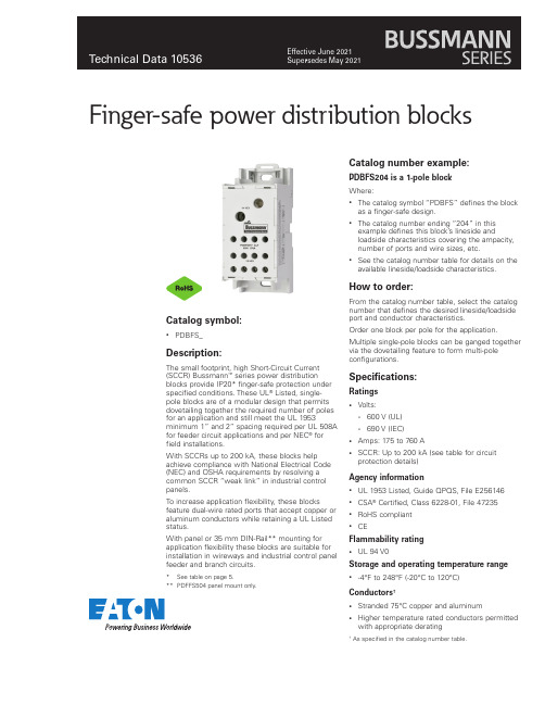
Finger-safe power distribution blocksCatalog symbol:• PDBFS_Description:The small footprint, high Short-Circuit Current (SCCR) Bussmann™ series power distribution blocks provide IP20* finger-safe protection under specified conditions. These UL® Listed, single-pole blocks are of a modular design that permits dovetailing together the required number of poles for an application and still meet the UL 1953 minimum 1” and 2” spacing required per UL 508A for feeder circuit applications and per NEC® for field installations.With SCCRs up to 200 kA, these blocks help achieve compliance with National Electrical Code (NEC) and OSHA requirements by resolving a common SCCR “weak link” in industrial control panels.To increase application flexibility, these blocks feature dual-wire rated ports that accept copper or aluminum conductors while retaining a UL Listed status.With panel or 35 mm DIN-Rail** mounting for application flexibility these blocks are suitable for installation in wireways and industrial control panel feeder and branch circuits.* See table on page 5.** PDFFS504 panel mount only.Catalog number example:PDBFS204 is a 1-pole blockWhere:• The catalog symbol “PDBFS” defines the block as a finger-safe design.• The catalog number ending “204” in this example defines this block’s lineside and loadside characteristics covering the ampacity, number of ports and wire sizes, etc.• See the catalog number table for details on the available lineside/loadside characteristics.How to order:From the catalog number table, select the catalog number that defines the desired lineside/loadside port and conductor characteristics.Order one block per pole for the application. Multiple single-pole blocks can be ganged together via the dovetailing feature to form multi-pole configurations.Specifications:Ratings• Volts:• 600 V (UL)• 690 V (IEC)• Amps: 175 to 760 A• SCCR: Up to 200 kA (see table for circuit protection details)Agency information• UL 1953 Listed, Guide QPQS, File E256146• CSA® Certified, Class 6228-01, File 47235• RoHS compliant• CEFlammability rating• UL 94 V0Storage and operating temperature range • -4°F to 248°F (-20°C to 120°C)Conductors†• Stranded 75°C copper and aluminum• Higher temperature rated conductors permitted with appropriate derating† As specified in the catalog number table.2Technical Data 10536Effective June 2021Finger-safe power distribution blocks/bussmannseriesFeatures and benefits•IP20 finger-safe under specified conditions increases safety by isolating energized connections.•Wire-ready captive termination screws cannot be misplaced and are shipped “backed out” to save time on conductor installation.• Sliding DIN-Rail latch provides easy block mounting.•For multiple pole applications, all single-pole units can be gang mounted by using the interlocking dovetail pins that are pre-installed on the side of the blocks.•Elongated panel-mounting holes provide greater flexibility and installation ease when matching up with drilled panel holes.Dual wire port application•Rated for dual wire port application to increase the possiblenumber of lineside and loadside connections. E.g., PDBFS220 can accept two wires into the lineside port (#4 - #14 Cu, #4 - #8 Al) and two wires per port (eight connections total) on the loadside lug (#8 - #14 Cu, #8 Al).•Dual wire applications are only viable when using two wires of the same size, stranding, and insulating and conductor material.Ferrule terminal application•Bussmann series PDBFS power distribution blocks are rated for use with UL Listed ferrules (see catalog number table for details).•Ferrule applications allow for the use of a broader range of conductor stranding and simulate a more efficient, solid wire connection with the PDBFS terminal port.•Always use UL Listed ferrules in accordance with the manufacturer’s specifications and instructions.Catalog numbers:(customer supplied) applied according to the manufacturer’s specifications. Ferrule ratings apply to copper wire only.** See pages 4 and 5 for the tested upstream overcurrent protective devices necessary for achieving these SCCRs.† Torque rating for dual wire and ferrule application is 30.5 N•m (270 Lb-in).†† Torque rating for ferrule application is 13.6 N•m (120 Lb-in).3Finger-safe power distribution blocksTechnical Data 10536Effective June 2021/bussmannseries Selecting SCCR power distribution blocks and terminal blocksShort-circuit current rated power distribution blocksBussmann series power distribution blocks have three distinct styles to match different application needs. There are the PDBFS_ and PDB_ high short-circuit current rated power distribution blocks and the 16_ power terminal blocks. The differences are whether the power distribution blocks are enclosed or not, and whether they are UL 1953 Listed power distribution blocks or UL 1059 Recognized power terminal blocks, which have different minimum spacing requirements. The table on this page will assist you in selecting which block is right for your application.Why these are importantPer the NEC and OSHA, equipment cannot be installed in anelectrical system at a location where the available fault (short-circuit) current is greater than the equipment’s SCCR.Further, equipment SCCRs are required in the 2014 NEC and for UL 508A Listed control panels. Marking the equipment SCCR on control panels (NEC 409.110), industrial machinery electrical panelsSelection tableThis table provides an overview of the three Bussmann series power distribution and terminal blocks mentioned above. For details on the PDB_ blocks, see data sheet number 10537. For the 16_ blocks, see data sheet numbers 10533 (UL Recognized power distribution blocks),10534 (splicer blocks) and 10535 (stud blocks).PDBFS_distribution blocksY es***Y es Y es Y es Y es Y es Y esPDB_UL 1953 Listed powerdistribution blocksNo †Y es Y es Y es Y es Y es Y es, with optional cover 16_UL 1059 Recognizedterminal blocksNo †Y esNo ††Y esNo ††Y esNo* When protected by proper fuse class with maximum ampere rating specified or smaller.** For details, see PDB and TB minimum spacing requirements for equipment table below.*** IP20 finger-safe under specific conditions, see data sheet page 5.† Optional covers are available. Not IP20, but provide a safety benefit.††No, except: Y es, if single pole units installed with proper spacings.Power distribution and terminal block minimum spacing requirements for equipment508A branch circuits 3/8”1/2”1/2”1995 HVAC3/8”1/2”1/2”Note: Refer to specific UL standards for complete spacing details.(NEC 670.3(A)), and HVAC equipment (NEC 440.4(B)) is required by the NEC.Power distribution and terminal blocks not marked with a component SCCR are typically one of the weakest links in a control panel’s equipment SCCR and may limit the equipment SCCR to no more than 10 kA. The PDBFS_ and PDB_ products have the increased spacing required for use in feeder circuits of equipment listed to UL 508A (UL 1059 terminal blocks must be evaluated for proper spacings). Also, for building wiring systems, the PDBFS_ andPDB_ power distribution blocks can be used to meet the 2014 NEC requirements in section 376.56(B) for power distribution blocks in wireways.See the last page of this data sheet for SCCR tools and resources to help you further understand and solve your SCCR needs.4Technical Data 10536Effective June 2021Finger-safe power distribution blocks/bussmannseriesUpstream fusing for SCCR and minimum enclosure dataThis table contains the tested SCCR levels for each PDBFS power distribution block using the specified lineside and loadside conductors and Bussmann series Class J, RK1, RK5 and T fuses. Using these tested SCCR levels also requires the power distribution block be installed in anenclosure with the minimum size indicated for each catalog number.PDBFS2202/0 - #8#4 - #1220010060200200 kA 16 x 16 x 6.75#4 - #1417510030175100 kA 2001006020050 kA PDBFS303350 - #6350 - #6400200100400200 kA 36 x 30 x 12.625PDBFS330500 - #6#2 - #6400200100400200 kA 24 x 20 x 6.75#6 - #142001006020050 kA 17510030175100 kA PDBFS377300 - #4#4600400200600200 kA 24 x 20 x 6.75400200100400100 kA #4 - #142001006020050 kA #4#460040020060050 kA PDBFS500350350600400200600200 kA 36 x 30 x 12.625350 - #4350 - #4600400200600100 kA PDBFS504500500600600200800**200 kA 36 x 30 x 12.625500 - #6500 - #6600400200600100 kAAmpacities 75°C per NEC ® Table 310.16 and UL 508A Table 28.1.* Class G 60 A (SC-60) or less or Class CC 30 A (LP-CC-30, FNQ-R-30, KTK-R-30) or less are suitable for all SCCRs in this table.** Class L 800 A (KRP-C 800_SP) or less fuses suitable for this particular SCCR case.Upstream circuit breakers for SCCR and minimum enclosure dataThis table contains the tested SCCR levels for each PDBFS power distribution block using the specified lineside and loadside conductors and Eaton and General Electric circuit breakers. Using these tested SCCR levels also requires the power distribution block be installed in an enclosure with the minimum size indicated for each catalog number.PDBFS SCCR as rated with Eaton circuit breakersPDBFS2042/0 - #82/0 - #865480E125H, EGB125, E125B, EGE125,E125G, EGS125, E125S, PDG13P , PDG13M12516 x 16 x 6.75PDBFS330500 - #3#2 - #814480LGH400, L400H, LGE400, L400E, LGS400, L400S, PDG33M, PDG33G, PDG33K 40024 x 20 x 6.7525LGC400, L400C, LGU400,L400U, LGX400, L400X, PDG33P PDBFS377(2) 300 - #2#430480LGH600, L600H, LGE600, L600E, LGS600, L600S, PDG33M, PDG33G, PDG33K60024 x 20 x 6.75#618#814#442LGC600, L600C, LGU600,L600U, LGX600, L600X, PDG33P#635#8145Finger-safe power distribution blocksTechnical Data 10536Effective June 2021/bussmannseriesPDBFS SCCR as rated with General Electric circuit breakersPDBFS2042/0 - #82/0 - #848016 x 16 x 6.7525SEHA, PEAC, PEBC,PEAE, PEBE150PDBFS2202/0 - #8#4 - #1265480SELA, PEAN, PEBN 15016 x 16 x 6.7525SEHA, PEAC, PEBC,PEAE, PEBE150PDBFS303250 - #6350 - #665480SFLA, PEDN, PEEN 25024 x 20 x 6.75250 - #635SFHA, PEDE, PEEE 2503/0 - #6350 - #665SELA, PEAN, PEBN 15025SEHA, PEAC, PEBC,PEAE, PEBE150PDBFS330250 - #6#2 - #1265480SFLA, PEDN, PEEN 25024 x 20 x 6.7535SFHA, PEDE, PEEE 2503/0 - #665SELA, PEAN, PEBN 15025SEHA, PEAC, PEBC,PEAE, PEBE150Specified installation conditions for IP20 finger-safe ratingsThis table contains the installed wire and trim lengths, and other conditions the PDBFS power distribution blocks need in order to be compliant withIP20 specifications. IP20 compliance status is indicated in the lineside and loadside wire port and terminal screw opening columns.PDBFS2202/0 - #80.75 (19)Y es Y es #4 - #14Top row 0.55 (14), Bottom row 0.85 (22)Y es Y es Screws fully opened N/A Y es No wire in hole No N/A PDBFS303350kcmil - 2/01.35 (34)Y es Y es 350kcmil - 2/01.25 (32)Y es Y es 1/0 - #6No Y es 1/0 - #6No Y es PDBFS330500 - 250kcmil1.25 (32)Y esY es #2 - #14Top row 0.59 (15), Bottom row 1.2 (30)Y es Y es 4/0 - #6No Y es Screws fully opened N/A Y es No wire in hole Y es N/A PDBFS377300kcmil - 4/0Top row 1.15 (29)bottom row 1.4 (36)Y esY es #4 - #14Top row 0.55 (14), Middle row 1.00 (35), Bottom row 1.22 (31)Y es Y es 3/0 - #4No Y es Screws fully open N/A Y es Screws fully open N/A No No wire in port Y es N/A No wire in port No N/A PDBFS500350kcmil - 2/01.25 (32)NoY es 350kcmil - 2/01.25 (32)Y esY es 1/0 - #4No Y es 1/0 - #4No Y es Screws fully opened N/A No Screws fully open N/A No No wire in port No N/A No wire in port No N/A PDBFS504500 - 350kcmil 1.25 (32)Y esY es 500 - 350kcmil 1.25 (32)Y esY es 300 - #6No Y es 300 - #6No Y es Screws fully open N/A No Screws fully opened N/A No No wire in portNoN/ANo wire in portNoN/A6Technical Data 10536Effective June 2021Finger-safe power distribution blocks/bussmannseriesDimensions — in (mm)PDBFS2201.03 (26) 3.73 (95) 2.15 (54) 3.55 (90) 2.92 (74)0.20 (5)0.40 (10)N/A PDBFS3031.54 (39) 4.66 (118) 2.87 (73) 4.49 (114) 3.82 (97)0.20 (5)0.44 (11)N/A PDBFS3301.54 (39) 4.66 (118) 2.87 (73) 4.49 (114) 3.82 (97)0.20 (5)0.44 (11)N/A PDBFS3771.88 (47) 4.66 (118) 2.93 (74) 4.49 (114) 3.82 (97)0.20 (5)0.44 (11)N/A PDBFS500 2.37 (60) 4.66 (118) 2.60 (66) 4.49 (114) 3.82 (97)0.20 (5)0.44 (11)N/APDBFS5042.54 (64)4.49 (114)3.15 (80)—3.82 (97)0.20 (5)0.35 (9)1.81 (46)LinesideLoadsideLinesideLoadsidePDBFS220PDBFS204PDBFS303PDBFS3307Finger-safe power distribution blocksTechnical Data 10536Effective June 2021/bussmannseries LinesideLoadsideLinesideLoadsideLinesideLoadsidePDBFS377PDBFS500PDBFS504Multi-pole block gangingPDBFS power distribution blocks are single-pole devices that can be ganged for the required number of poles using the interlocking dovetail pins that are pre-installed on each block.To interlock and gang two or more blocks (DIN-Rail or panel mount):•Place blocks of the same catalog number side-by-side and slide the dovetail pin of one block into the reciprocal slot on the other and press together until fully seated and the backs of both blocks are coplanar.•Repeat the step above until the number of desired poles are gangedNote: Dissimilar PDBFS blocks can be ganged together. E.g., a PDBFS204 can be ganged with a PDBFS220 using the interlocking dovetailing pins. Ganging a PDBFS504 with any other PDBFS will prevent DIN-Rail mounting.Dovetailing feature permits easy ganging for multi-pole applications8Finger-safe power distribution blocksTechnical Data 10536Effective June 2021Eaton, Bussmann and OSCAR are valuable trademarks of Eaton in the U.S. and other countries. Y ou are not permitted to use the Eaton trademarks without prior written con-sent of Eaton.CSA is a registered trademark of the Canadian Standards Group.NEC is a registered trademark of the National Fire Protection Association, Inc.UL is a registered trademark of the Underwriters Laboratories, Inc.Eaton1000 Eaton Boulevard Cleveland, OH Bussmann Division 114 Old State Road Ellisville, MO 63021United States/bussmannseries © 2021 EatonAll Rights Reserved Publication No. 10536June 2021Follow us on social media to get thelatest product and support information.For Eaton’s Bussmann series product information,call 1-855-287-7626 or visit:/bussmannseriesThe only controlled copy of this data sheet is the electronic read-only version located on the Eaton network drive. All other copies of this document are by definition uncontrolled. This bulletin is intended to clearly present comprehensive product data and provide technical information that will help the end user with design applications. Eaton reserves the right, without notice, to change design or construction of any products and to discontinue or limit distribution of any products. Eaton also reserves the right to change or update, without notice, any technical information contained in this bulletin. Once a product has been selected, it should be tested by the user in all possible applications.DIN-Rail mountingAll versions of the Bussmann series PDBFS power distribution blocks can be DIN-Rail mounted except for the PDBFS504, which can only be panel mounted.It is recommended for multi-pole applications that the individual blocks be ganged using the included dovetailing feature. See Multi-pole block ganging for details.To mount, perform the following:•Using an appropriate size flat blade screw driver, open the DIN-Rail latch that is on the lineside of each block.•Hook the loadside DIN-Rail tabs onto the lower edge of the 35 mm DIN-Rail•Rotate the block(s) up until they are seated over the upper and lower edges of the DIN-Rail•Push the DIN-Rail latch(es) down and into the locked position.To remove blocks, reverse the previous steps.Note: To prevent damage to the block housing when torquing the terminal screws, DIN-Rail end stops are required on each side of the block or ganged blocks.The recommended Bussmann series DIN-Rail end stops are:BRKT-NDSCRW2DIN-Rail end stop with screw-clamp anchorPanel mountingAll Bussmann series PDBFS power distribution blocks can be panel mounted. It is recommended for multi-pole applications that the individual blocks be ganged using the included dovetailing feature. See Multi-pole block ganging for details.Use two (2) suitable length #10 or M5 screws for each block being mounted. Use four (4) screws for each PDBFS504 block. The max torque for the mounting screws is 17 in-lbs (1.92 N •m).SCCR tools and resourcesEaton offers many resources that help customers understand and assess their SCCR needs.Please use the following whenever you have questions, concerns or just need help with SCCR ratings.Engineering services for SCCROSCAR™ compliance software eliminates the guesswork in equipment SCCR calculations.This innovative OSCAR compliance software assists customer compliance with new Code and standards requirements for short-circuit current ratings as they relate to control panels, equipment and assemblies. Go to and request a seven-day free trial.If your equipment SCCR needs improvement, contact the Bussmann Application Engineers for a free design review. Call toll-free1-855-BUSSMANN (855-287-7626) or email FuseT *************.Online SCCR tools and publications•Free SCCR Protection Suite online tool. An easy, fast way to search for components and their SCCRs. Visit .•Application notes:• Developing an effective SCCR plan for facilities and purchasers of industrial equipment — publication no. 10367•Developing an equipment SCCR standard for manufacturers of industrial equipment — publication no. 10368•Four steps to determine equipment SCCR — publication no. 10538• Equipment SCCR made easy brochure — publication no. 10374•SPD (Selecting Protective Devices) handbook; over 250 pages covering the application of overcurrent protective devices, SCCR and more — publication no. 3002。
Removable clamp assembly

专利名称:Removable clamp assembly 发明人:Lawrence R. Damour申请号:US08/296813申请日:19940826公开号:US05476437A公开日:19951219专利内容由知识产权出版社提供摘要:A removable clamp assembly for the ends of an elastomer sleeve of a spreader roller which includes and outer bearing ring, a clamp cup and a clamp cover. The outer bearing ring has a textured outer diameter which is sized to fit closely in said elastomer sleeve. The outer bearing ring also includes a central bore for mounting of an anti friction bearing therein. The clamp cup is sized to fit on the outer diameter of the elastomer sleeve and includes a plurality of clamp segments which are arrayed on the outer edge of an end ring. The segments have a tapered outer surface terminating in a mouth portion.A clamp cover is fitted onto and over the tapered outer surface thereby clamping said elastomer sleeve between the clamping segments and the bearing ring.申请人:CONVERTER ACCESSORY CORP.代理人:Patrick J. Pinto更多信息请下载全文后查看。
纵向限位板英语

纵向限位板英语The Vertical Limit Stop: A Critical Component in Industrial AutomationIn the ever-evolving landscape of industrial automation, the vertical limit stop has emerged as a crucial component that plays a pivotal role in ensuring the smooth and efficient operation of various machinery and equipment. This unassuming yet indispensable device is responsible for precisely controlling the movement and positioning of components, thereby enhancing the overall performance and reliability of industrial systems.At its core, the vertical limit stop is a mechanical device designed to limit the upward or downward travel of a moving part or component within a predefined range. This limitation is essential in a wide range of industrial applications, from robotic systems and CNC machines to material handling equipment and packaging lines. By establishing precise boundaries, the vertical limit stop helps to prevent potential collisions, damage to equipment, and even injuries to personnel.One of the primary functions of the vertical limit stop is to safeguard the integrity of the machinery or equipment. In the fast-paced and dynamic environment of industrial production, components can often reach their maximum travel limits, leading to potential impact or stress on the system. The vertical limit stop acts as a protective barrier, intercepting the movement and bringing the component to a controlled stop before it reaches the end of its range. This not only extends the lifespan of the equipment but also minimizes the risk of costly repairs and downtime.Moreover, the vertical limit stop plays a crucial role in maintaining the accuracy and repeatability of industrial processes. In applications where precise positioning is paramount, such as in CNC machining or robotic assembly, the vertical limit stop ensures that the moving parts consistently reach the desired coordinates, facilitating the production of high-quality parts and products. This level of precision is essential in industries where even the slightest deviation can have significant consequences, such as in the manufacture of medical devices or aerospace components.Beyond its role in safeguarding equipment and ensuring process accuracy, the vertical limit stop also contributes to the overall safety of the industrial environment. In scenarios where personnel work in close proximity to moving machinery, the vertical limit stop can serve as a crucial safety mechanism, preventing accidental collisions orentanglement with the equipment. By establishing well-defined boundaries, the vertical limit stop helps to create a safer workspace, reducing the risk of workplace injuries and enhancing the overall well-being of the workforce.The versatility of the vertical limit stop is another key factor that has made it an indispensable component in industrial automation. These devices can be designed and configured to suit a wide range of applications, from small-scale benchtop equipment to large-scale industrial machinery. Manufacturers often offer a variety of mounting options, adjustment mechanisms, and material choices to accommodate the specific needs of different industries and environments.In recent years, the advancement of technology has also led to the development of more sophisticated vertical limit stop solutions. Integrated sensor systems, for instance, can provide real-time feedback on the position and status of the moving components, allowing for more precise control and monitoring. Additionally, the incorporation of programmable logic controllers (PLCs) and advanced control systems has enabled the integration of vertical limit stops into broader automation strategies, further enhancing the overall efficiency and responsiveness of industrial operations.As the demand for higher productivity, quality, and safety continuesto drive the evolution of industrial automation, the role of the vertical limit stop is only expected to grow in importance. Manufacturers and engineers are constantly exploring new ways to optimize the performance and functionality of these critical components, ensuring that they remain at the forefront of industrial innovation.In conclusion, the vertical limit stop is a fundamental element in the world of industrial automation, serving as a vital safeguard for equipment, a guarantor of process accuracy, and a contributor to workplace safety. Its versatility, reliability, and technological advancements have made it an indispensable component in a wide range of industrial applications, from manufacturing and material handling to robotics and packaging. As the industrial landscape continues to evolve, the vertical limit stop will undoubtedly remain a cornerstone of modern industrial automation, enabling manufacturers to push the boundaries of efficiency, productivity, and safety.。
CLAMP FOR A DUPLICATING MACHINE FOR BITTED AND DOU

专利名称:CLAMP FOR A DUPLICATING MACHINE FOR BITTED AND DOUBLE-BITTED KEYSPROVIDED WITH A COLLAR ON THE SHANK 发明人:DA RODDA, Oreste申请号:EP14845033.1申请日:20141106公开号:EP3065904B1公开日:20170517专利内容由知识产权出版社提供摘要:A clamp (2, 2') for a duplicating machine for bitted and double-bitted keys provided with a collar (16) on the shank (14), with jaws (10, 10') for clamping said key (6, 6'), said clamp comprising a locator element (26) of adjustable position such that, when a key (6, 6') is clamped between said jaws (10, 10'), the collar (16) of said key (6, 6') rests against said locator element (26), characterised in that said locator element (26) comprises a portion (24) which can be withdrawn from said clamp in a manner parallel to the axis of the shank (14) of the key (6, 6') when clamped between the jaws (10, 10') of said clamp, and a locator bar (34) extending in a direction substantially perpendicular to said withdrawable portion (24) and interacting with said collar (16), and in that said withdrawable portion (24) of the locator element (26) is provided with a plurality of notches (28) spaced apart in the withdrawal direction and selectively snap-engagable by an elastic engagement element (30, 32) with which said clamp (2, 2') is provided.申请人:SILCA S.p.A.代理机构:Piovesana, Paolo更多信息请下载全文后查看。