
EJJ-5完整使用说明书
EJJ--5 型
线材扭转试验机使用说明书宁夏青山试验机有限公司
目录
一.用途及使用范围 (1)
二.主要技术性能规范 (1)
三.结构原理 (2)
四.试验机的安装 (3)
五.电气原理 (3)
六.使用方法及规则 (4)
七.试验机的调整和维护 (4)
八.成套一览表 (5)
九.附图 (6)
附图(一):结构总图 (6)
附图(二):电气原理图 (7)
附图(三):安装地基图 (9)
一.用途及使用范围
EJJ-5型线材扭转试验机是做线材扭转试验的设备,根据试样破断时的转数及表面状态来确定材料的塑性及不均匀性。
本试验机用于对试样直径为Φ1—Φ5mm的金属线材进行扭转试验。
二.主要技术性能规范
1.试样直径Φ1—Φ5 mm
2.试样长度 100—500 mm
3.预加张紧力 2—300 N
4.试验机转速 60 , 90 , 120 r/min
5.记数范围 0—99 r
6.电动机型号 Y06324
功率 250 w
转速 1400 r/min
电压 380 V 、50 HZ
7.外型尺寸(长*宽*高)(mm) 1100*370*1065
三.结构原理
如附图一,本机主要由底座、机身、减速箱、左右夹持器、防护罩、左轴架、尾架、砝码吊架、电控系统、数显系统等零部件组成。
电机通过三角带与减速箱联结,减速后带动右夹持器转动。
左夹持器可轴向移动,但不能转动。
左右夹持器内都装有钳口,用以夹紧试样。
左轴架可以根据试样的长短紧固在机身上的不同位置,由指针20在导轨平面的刻度上指出左右夹持器之间的距离。
当装夹试样时,转动手把11,使左夹持器伸出,待夹紧试样后,再转动手把11,使凸轮脱开,试样被拉紧。
当试样破断后,左夹持器在拉紧力的作用下迅速左移,定位板接触光电开关18,电源中断,数显系统记录试样破断时的扭转圈数。
在机身的导轨上装有防护板,可按试样长短将试样紧固在导轨的适当位置上。
更换三角皮带在塔轮上的位置,可分别得到需要的三种速度60、90、120r/min。
四.试验机的安装
试验机应通过地脚螺栓安装在坚固的地面上。
安装后试验机机身导轨平面的水平度误差应不大于0.2/1000。
接通电源后,从正面看,右夹持器应向外翻转。
五.电气原理
本机现在经过改进后从结构上更合理更简单更可靠。
整个电路采用数字集成电路,主电路采用了固态继电器。
设计合理结构简单。
使用和维修都很方便。
合上空气开关,电压通过一个小变压器给电路板提供电源,经整流滤波后得到五伏直流电压供给电路工作用。
电路在输出端输出一个电压控制固态继电器的导通和关闭,来达到控制电机的运转和停止。
通电后停止按键上的红色指示灯亮,计数器显示00的字样。
如果有数字可以按复位键进行复位。
计数器是通过主轴上的一个遮光板使光电对管导通﹑关闭而产生脉冲。
脉冲信号输入到集成电路里整形后产生方波提供给计数器计数用。
在机器左边的活动卡头架上,安装有一个碰停开关。
此开关低电位有效【接地】。
通电机器处于正常状态后就可以进行试验了。
六.使用方法及规则
试验时,先根据试样长度把左轴架固定在适当位置上,转动手把,使左夹持器伸出,夹紧试样后将转座转回原位置,加上砝码使试样承受所需的预紧力。
把防护板移至试样中间位置。
对计数器清零。
接通电源,启动电机,进行试验。
试验时,注意的事项:
1.试样需矫直时,必须在木垫板等软材料上进行,试样上不许有任何伤痕。
2.试样必须装夹在夹持器中心。
七.试验机的调整和维护
1.试验机必须经常保持洁净。
2.转动部分和滑动部分应根据使用情况加入清洁的机油进行润滑,轴承注入黄油。
3.未油漆电镀的表面应经常擦试并涂防锈油。
八.成套一览表
九.附图
附图(一):结构总图
1.底座
2.电源插座
3.空气开关
4.电动机
5.三角皮带
6.机身
7.减速箱
8.右夹持器
9.防护罩 10.左夹持器 11.手把 12.左轴架13.钢丝接头 14.绳轮 15.尾架 16.钢丝绳17.砝码吊架 18.光电开关 19.锁紧螺母 20.指针21.定位板 22.标牌 23.腰盘 24.开关按钮
附图(二):电气原理图
附图(三):安装地基图。
yudian宇电AIJ五位(测量控制)数字仪表说明书
上窗为pv下窗为程序段测量值pv为80000给定值sv为80005上窗为pv下窗为剩余时间程序设置状态第1段程序起点给定值为8005下一程序下一参数上窗为pv下窗表示功率的参数设置状态上限报警参数值为1005仪表上电pvsv20ma快捷操作功能aij的功能可以用修改参数的方式的来完成但对于部分常用的功能如修改给定值及程序的运行停止操作等等我们设计了快捷操作来简化使用这些快便捷方式也可以设置成禁止使用以防止误操作
通讯接口(COMM):可安装S或S4模块(RS485通讯接口)用于与计算机通讯,也可安装电压输出模块给外部传感 器供电。
1.3.2 常用模块型号
L1 大容量继电器(国产宏发8A/250VAC)常开触点开关输出模块(模块容量:250VAC/2A)。 L2 继电器常开+常闭触点开关输出模块(模块容量:30VDC/1A,250VAC/1A,适合报警用)。 L4 大容量继电器(进口品牌8A/250VAC)常开触点开关输出模块(模块容量:250VAC/2A)。 L5 双路继电器(松下NAIS 5A/250VAC)常开触点开关输出模块(容量:30VDC/2A,250VAC/2A)。 W 1、W 2 可控硅无触点常开式(W2为常闭式)输出模块(容量:100~240VAC/0.2A,“烧不坏”特点)。 G(DC 12V/30mA)、GJ(DC 5V/30mA)固态继电器驱动电压输出模块。 G5 双路固态继电器驱动电压输出模块。 K1/K3 单路/三路“烧不坏”可控硅过零触发输出模块(每路可触发5~500A双向或二个反并联的单向可控硅)。 K5/K6 单路220VAC/380VAC “烧不坏”单路可控硅移相触发输出模块(可触发5~500A双向或二个反并联的单向可控 硅)。 K5A 功能同于K5模块,但对于感性负载具有更好的波形与线性。 X3 光电隔离的可编程线性电流输出模块。 X5 自带隔离电源的光电隔离型可编程线性电流输出模块。 S 光电隔离RS485通讯接口模块。 S4 自带隔离电源的光电隔离RS485通讯接口模块。 R 光电隔离的RS232C通讯接口模块。 V24/V12/V10 隔离的24V/12V/10V直流电压输出,可供外部变送器或其它电路使用,最大电流50mA。 I2 开关量/频率信号输入接口,可用于外部开关接点或频率信号输入,含12VDC电源输出供外部传感器使用。 I4 模拟量4~20mA/0~20mA 输入接口,含24VDC/25mA 电源输出供二线制变送器使用。 I5V,I10V,I200,I500线性电压输入模块。
亿格瑞V5产品参数说明书
外挂字幕
pgs,srt,smi,sub,ssa,ass,sub+.idx
音频编码格式 MPEGILAYER1/2/2.LPCM.PCM.FLAC
音频播放格式 APE,M4A,MPEGAUDIO,MP1,MP2,MP3,MPA,WAV,OGG
图片格式
JPG,BMP,GIF,TIF
最大分辨率
最大支持 6400 万像素的图片硬解码
1、“我的电视”方便您直接找到观看历史和收藏的影片,并可以在多个视频网站的影片库中直接搜索喜爱的影片; 2、“影视”是多个视频网站的聚合视频,直接解决了旧时家庭影院买碟、用碟、放置碟片的烦恼,随点随看、画 面清晰、片源众多; 3、“直播”整合了海量在线电视直播频道; 4、“亿趣家庭”独家特色功能,整合了一家老少喜爱的 TV 应用。是真正的为电视开发的版本,遥控器上下左右 OK 键就可以灵活操控,老人家小孩子不仅会用,而且爱用。 5、“互联网”包含华数、电视回放、凤凰资讯、看天下、网络 MTV、网站导航,各类网络应用应有尽有; 6、“应用”包含软件管理、应用商店、影音媒体、文件浏览,可以方便的找到各种游戏、影音等等应用扩展客厅 的娱乐功能; 7、“设置”可以让您完成对本机做包括网络、显示等相关内容的设定;
深圳市亿格瑞科技有限公司
产品型号:客厅电脑 V5
简介
产品规格书
亿格瑞客厅电脑V5,不仅仅可以让用户在客厅可以轻易播
放喜爱的影视节目,更直接做到了游戏、娱乐、教育、购物、分享 的功能,并对第三方APK应用有良好的支持,而且自身集成了流畅 的红外控制和有趣的“多屏互动”,让用户体验达到目前科技的极 致。
安卓版本 UI
HDMI v1.3 数字高清接口,CVBS 复合视频 左右立体声 150M 802.11 b/g/n 10/100M 自适应网络接口 USB 2.0 host x 2 外置适配器,DC 5V 3A
第吉尔门锁软件使用说明书

---门锁软件使用流程说明书-----------------------------------------------第吉尔企业股份有限公司门锁系统管理软件第一部分软件的安装1、安装本司配置的读写器,一定要确保串口与读写器连接牢固,并接上电源↓2、启动计算机进入Windows↓3、将光碟放入CD-ROM(光驱)↓4、打开“我的电脑”,进入光盘,用鼠标双击“setup.exe”文件进行安装(安装过程中遇到所有的对话框均选择“确定”即可)↓5、安装完毕后,重新启动计算机。
第二部分软件的操作一、门锁的各类设定:(一)、登录1. 点击桌面图标运行系统。
2. 系统出厂时默认的用户代码为0,密码为空。
用户代号:0 ,密码:为空3. 如果在使用当中遗失密码,可以输入以下代码用户代号:为空,密码:197209此时登录的用户可以读取[特别卡],修改增添用户,修改其他用户的登录密码(注意该用户没有发卡的权限)。
如果密码和[特别卡]同时遗失将不能登录系统,所以请妥善保管好[特别卡]。
(二)、使用特别卡1.系统第一次使用时必须用[特别卡]激活,方法如下:a)进入系统,将[特别卡]插入发卡机,点击[查卡]。
系统显示为:输入A,B,C级密码(可以随意输入,请紧记)。
输入酒店名称(可以随意输入)。
起始卡号:为空(如果电脑故障,系统重装时才使用)。
点击[确定]保存退出,此时系统已经激活。
b)此时可以点击[用户管理]增添用户,修改其权限和密码(具体操作为:单击“操作员管理”→输入操作员代码、姓名,输入完第一个操作员资料后可双击该用户进行修改其权限和密码→单击“添加”,接着输入第二个操作员资料→依次类推。
全部操作员资料输入完毕后→单击“关闭”退出操作员管理)。
(三)、门锁设置每一个门锁使用前,必须完成初始化过程,初始化的步骤是:第一步:先插复位卡(绿灯亮)->设置门锁所属酒店ID身份证第二步:再插设置卡(绿灯亮)->设置门锁房号第三步:再插入时间卡(绿灯亮)->设置门锁当前的时间每张卡插入时,门锁必须亮绿灯,方表示插卡有效,亮红灯则无效。
ZD6-EJJ型直流三机牵引道岔控制电路的改进
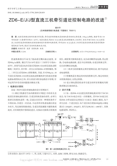
19科技资讯 SCIENCE & TECHNOLOGY INFORMATIONDOI:10.16661/ki.1672-3791.2019.28.019ZD6-E/J/J型直流三机牵引道岔控制电路的改进①徐兴平(兰州铁路局银川电务段 宁夏银川 750011)摘 要:道岔是铁路运输的关键行车设备,牵引道岔的转辙机是铁路电务系统的主要设备。
50kg/m钢轨,辙岔号为1/18号的道岔(工务图号专线01-4275),电务设备采用ZD6-E/J/J型直流电动转辙机三机牵引。
该文介绍了ZD6-E/J/J型直流三机牵引道岔的转辙机控制电路的设计原则和电路原理,针对ZD6-E/J/J直流三机牵引道岔控制电路存在的问题和隐患做出了分析,提出了具体的电路改进方案。
关键词:铁路信号 道岔 控制电路 改进中图分类号:U284文献标识码:A文章编号:1672-3791(2019)10(a)-0019-02普速铁路部分车站为了提高道岔侧向通过速度,采用50kg/m钢轨,辙岔号为1/18号道岔(工务图号专线01-4275),该型号道岔电务设备采用ZD6-E/J/J型直流电动转辙机三机牵引,其中第一牵引点采用ZD6-E型转辙机,第二、三牵引点采用ZD6-J型转辙机。
目前,针对50kg/m、18号道岔采用ZD6-E/J/J型直流电动转辙机牵引的道岔控制电路标准图尚未公布,该文着重分析该电路设计原则,针对运用当中存在的问题提出修改方案。
1 电路设计原则直流三机牵引道岔控制电路的设计原则如下。
(1)满足《铁路信号站内联锁设计规范》中的有关直流道岔控制电路的要求:①道岔转换设备的动作,必须与值班员的操纵意图一致;②道岔在任何一种锁闭条件下不得启动;③道岔一经启动,不论其所在轨道电路区段是否有车,均应继续转换到底;④道岔因故被阻不能转换到底时,对非调度集中操纵的道岔,应保证经操纵后转换到原位,调度集中操纵的道岔,应自动切断供电电路,停止转换;⑤电机电路故障,道岔不应再转换;⑥道岔转换完毕,应自动切断启动电路。
津制 ES-E 系列电子分析天平 使用说明书

津制00000697号ES-E系列电子分析天平使用说明书上海力辰邦西仪器科技有限公司目录(中文)1技术数据 (1)1.1尺寸示意图(mm) (2)2设备概述 (3)2.1按键示意图 (3)2.2显示屏信息 (4)3基本信息(常规) (6)3.1用途 (6)3.2不当操作 (6)3.3保修 (6)3.4附属配件的检测 (6)4安全预防 (6)4.1注意操作手册的指示 (6)4.2人员培训 (6)5运输与保存 (6)5.1验收 (6)5.2包装/退货运输 (7)6拆箱、安装与调试 (9)6.1安装场所与使用场地 (9)6.2拆箱、检测与安装 (10)6.3调整水平 (11)6.4接通电源 (11)6.5初步调试 (12)6.6外围设备连接 (12)7校准 (12)7.1使用推荐的校准砝码校准 (12)7.1.1用100g砝码校准 (14)7.2内校砝码校准(仅限内校型天平) (15)7.2.1全自动内校 (15)7.2.2半自动内校(一键校准) (15)8基本操作 (16)8.1启动 (16)8.2切换到待机模式 (16)8.3归零 (17)8.4样品称重 (17)8.5单位变换 (17)8.6使用容器称量 (17)9应用 (18)9.1计数称量 (18)9.2百分比计量 (20)10菜单 (21)10.1菜单导航 (21)10.2菜单概览 (23)11RS232C-接口 (24)11.1技术数据 (24)11.2接口电缆 (25)11.3接口参数 (25)11.3.1波特率 (25)11.3.2输出条件 (25)11.4示例 (26)11.5电脑按键指令 (26)12维修、维护 (26)12.1清洁 (26)12.2服务与维护 (26)13故障检测 (26)1技术数据ES-E系列电子分析天平(0.01mg可读性、全自动校准型)型号ES1055A ES2085A 称量范围(最大)120g/51g210g/82g 可读性(d)0.1mg/0.01mg重复性±0.1mg/±0.05mg线性±0.1mg/±0.05mg稳定时间 2.5秒/15秒预热时间30-60分钟称量单位g,oz,ct,lb计件称量的最小称重0.1mg计件称量的参考数量5,10,20,50,100秤盘(不锈钢)ø90mm净重(kg)6可允许的环境条件+10°C to+30°C环境湿度范围20~85%相对(非冷凝)电源输入电压AC230V,50-60Hz接口RS232CES-E系列电子分析天平(0.01mg可读性、外部砝码校准)型号ES1035B ES2055B 称量范围(最大)120g/31g210g/51g 可读性(d)0.1mg/0.01mg重复性±0.1mg/±0.05mg线性±0.1mg/±0.05mg 建议(不提供)的校准砝码(级别)100g(E2)稳定时间 2.5秒/15秒预热时间30-60分钟称量单位g,oz,ct,lb计件称量的最小称重0.1mg计件称量的参考数量5,10,20,50,100秤盘(不锈钢)ø90mm净重(kg)6可允许的环境条件+10°C to+30°C环境湿度范围20~85%相对(非冷凝)电源输入电压AC230V,50-60Hz接口RS232C1.1尺寸示意图(mm)2设备概述位置设计1显示屏2操作侧面防风罩的把手3可调地脚4气泡水准仪5防风罩6秤盘7防风环组件2.1按键示意图按键功能·开机/关机·退出菜单·校准·去皮·归零·保存设置·变换称重单位·选择一个应用程序·确定如何保存参考值·开/关显示屏的背景照明(连续两次按此键)·改变菜单设置·打印显示的值2.2显示屏信息序号显示描述1稳定值显示2天平处于待机状态3读取单位“克”4读取单位“克拉”5读取单位“英磅”6读取单位“盎司”7计数称量状态8密度单位9普通称重模式10计数称重模式11百分比称重模式12密度测量模式13检重称量模式14黄金k值15天平最大量程16最小可读数17空气中样品重量(密度测量模式)18液体中样品重量(密度测量模式)19称量值为正值20称量值为负值21检重模式-超重22检重模式-欠载23固体密度测量模式24液体密度测量模式25黄金密度测量模式3基本信息(常规)3.1用途您购买的这款天平是用于确定被称量物体的称量数值的。
ZD6-EJJ型直流三机牵引道岔控制电路的改进
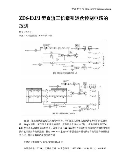
ZD6-E/J/J型直流三机牵引道岔控制电路的改进作者:徐兴平来源:《科技资讯》2019年第28期摘; 要:道岔是铁路运输的关键行车设备,牵引道岔的转辙机是铁路电务系统的主要设备。
50kg/m钢轨,辙岔号为1/18号的道岔(工务图号专线01-4275),电务设备采用ZD6-E/J/J型直流电动转辙机三机牵引。
该文介绍了ZD6-E/J/J型直流三机牵引道岔的转辙机控制电路的设计原则和电路原理,针对ZD6-E/J/J直流三机牵引道岔控制电路存在的问题和隐患做出了分析,提出了具体的电路改进方案。
关键词:铁路信号; 道岔; 控制电路; 改进中图分类号:U284 ; ; 文献标识码:A 文章编号:1672-3791(2019)10(a)-0019-02普速铁路部分车站为了提高道岔侧向通过速度,采用50kg/m钢轨,辙岔号为1/18号道岔(工务图号专线01-4275),该型号道岔电务设备采用ZD6-E/J/J型直流电动转辙机三机牵引,其中第一牵引点采用ZD6-E型转辙机,第二、三牵引点采用ZD6-J型转辙机。
目前,针对50kg/m、18号道岔采用ZD6-E/J/J型直流电动转辙机牵引的道岔控制电路标准图尚未公布,该文着重分析该电路设计原则,针对运用当中存在的问题提出修改方案。
1; 电路设计原则直流三机牵引道岔控制电路的设计原则如下。
(1)满足《铁路信号站内联锁设计规范》中的有关直流道岔控制电路的要求:①道岔转换设备的动作,必须与值班员的操纵意图一致;②道岔在任何一种锁闭条件下不得启动;③道岔一经启动,不论其所在轨道电路区段是否有车,均应继续转换到底;④道岔因故被阻不能转换到底时,对非调度集中操纵的道岔,应保证经操纵后转换到原位,调度集中操纵的道岔,应自动切断供电电路,停止转换;⑤电机电路故障,道岔不应再转换;⑥道岔转换完毕,应自动切断启动电路。
(2)三机牵引的转辙机应顺序错峰启动,错开电机启动电流峰值。
(3)转辙机需在规定的时间内转换完毕;规定时间内未转换到底时,应停止转换。
ZDJ-5型自动滴定仪操作规程
ZDJ-5型自动滴定仪操作规程1.目的为规范ZDJ-5型自动滴定仪操作,特制定本程序。
2.适用范围本程序适用于ZDJ-5型自动滴定仪操作。
3.准备3.1开机前,首先应对仪器做一次检查。
看仪器正常使用条件是否完全保证,看基本部件安装是否到位,看各供流管路接头连接是否可靠。
检查电气线路各种连接是否匹配、正确。
使用复合电极测试时,复合电极的电气插头应插入电极插口(1)上;使用测量电极与参比电极测试时,插口(1)上应插入Q9短路插头,其它两个电极分别与测量电极接口(2)接线柱(一)连接好。
(注意:任何测试,电极插口(1)都不得空置)。
3.2检查滴定剂的容积,不能少于5ml。
如选择《氧化还原滴定》模式,溶液杯内溶液不能少于100ml。
3.3如上次试验采用了会产生沉淀或结晶的滴定剂(如硝酸银AgNO3),应对滴定管做认真清洗,以免产生结晶损坏阀门。
3.4开机前不得更换滴定管。
(必须使仪器上在用的滴定管完成一次补液动作,使活塞处于下死点位置时,方可进行更换)。
4.开机运行4.1“输入”键:相当于计算机中的回车键,按压此键可将参数或命令输入仪器,并使仪器进入到下一步工作状态。
在以后的操作步骤说明中用“↙”表示按压此键。
4.2“Ye/No”键:人—机对话时,答“是”或“否”。
按一次为“Ye”,再按一次为“No”。
4.3“修改”键:按下此键,可将原来设定的某一个号数进行修改。
4.4“手动”键:当仪器处于起始准备状态时,按此键仪器即进入手动滴定模式。
4.5“测试”键:当仪器处于起始准备状态时,按此键仪器可进入“mv”测量功能或打印测试功能。
4.6“清洗”键:当仪器处于起始准备状态时,按此键仪器即能自动进行滴定清洗。
4.7“补液”键:当仪器处于起始准备状态时,按此键仪器即能自动补液至满管。
4.8“终止”键:按此键,可终止仪器正进行的任何操作,返回起始准备状态。
4.9标定电极:pH玻璃电极需定期进行标定,并记录下该电极的零pH电位(E0)值。
Jabra Elite 5 用户手册说明书
Jabra用户手册© 2022 GN Audio A/S.保留所有权利。
Jabra®是 GN Audio A/S 的注册商标。
Bluetooth®字标和徽标是 Bluetooth SIG, Inc. 的注册商标,GN Audio A/S 经许可使用该标志。
中国制造型号:O TE170R/OTE170L/CPB1701. 欢迎 (5)2. Jabra Elite 5 概览 (6)2.1 包含的配件3. 如何佩戴 (8)3.1 更换耳胶4. 如何充电 (10)4.1 为耳机充电4.2 为耳塞式耳机快速充电4.3 使用 USB 为充电盒充电4.4 使用 Qi 认证无线充电板为充电盒充电5. LED 指示灯的含义 (14)6. 如何配对 (16)6.1 与移动设备配对6.2 与 Windows 电脑迅速配对 (Swift Pair)7. 使用方式 (18)7.1 开启/关闭耳机7.2 音乐控制7.3 通话控制7.4 语音助手控制7.5 可调式主动降噪7.6 透听模式7.7 Spotify Tap 播放7.8 Sidetone7.9 单耳塞模式7.10 自动暂停音乐7.11 自动静音麦克风7.12 MyControls7.13 休眠模式7.14 处理多个通话7.15 Multipoint | 多点7.16 更新固件7.17 重置耳机8. Jabra Sound+ app (33)9. 支持 (34)9.1 常见问题解答9.2 如何保养耳塞9.3 替换配件9.4 使用替换耳塞9.5 使用替换充电盒1. 欢迎感谢您使用 Jabra Elite 5。
希望您使用愉快!Jabra Elite 5 产品特性• 混合式主动降噪技术可屏蔽更多背景噪音• 使用专业麦克风的 6 麦克风通话技术,有效降低风噪• 精心调校的 6 毫米扬声器让音乐惊艳响起• 电池续航时间约 7 小时,搭配无线充电盒可长达约28 小时,还有快速充电功能。
5E电机轴使用和维护手册说明书
USE AND MAINTENANCE MANUALSERIES 5E ELECTROMECHANICAL AXESSeries 5E electromechanical axes2Contentsi. Introduction 31. General safety warnings 32. Reference documents 33. Components and materials 44. Coding 45. Transport and packaging 56. Storage 57. Installation 5Fixing on a continuous surface 5 Fixing on 2 or more supports 6 Fixing accessories 7 Connections to the slider 8 Interfaces for multi-axis mounting 9 Instructions for multi-axis mounting 9 Motor connections 10 FR-5E connection 11 FR-5E-50-GC and FR-5E-80-GC connection 12 FRH-5E-50 and FRH-5E-65 connection 14 FRH-5E-80 connection 15 FS-5E connection 17 Parallel shaft 18 Parallel shaft connection 18 Locking Set 19 Elastic expansion coupling 19 Fixing of the sensors 208. Maintenance 209. Dismantling and parts replacement 2110. Disposal 2111. Technical information 2112. Resolution of any failure21Series 5E electromechanical axesSeries 5E electromechanical axesComponents and materialsCodingPARTSMATERIALS1 End cap Aluminium alloy2 PulleySteel3 End cap bumper Technopolymer4 Protection plate Steel5 Slider Aluminium alloy6 Bumper Technopolymer7 Toothed beltPU + Steel 8 Recirculating ball guideSteel5E SERIESS PROFILE:S = square section 050FRAME SIZE:050 = 50x50 mm 065 = 65x65 mm 080 = 80x80 mm TBL TRANSMISSION:TBL = toothed belt0200STROKE [C]:0050 ÷ 4000 mm for size 0500050 ÷ 6000 mm for sizes 065 and 080 A VERSIONS:A = standard axis D = support axisH = reinforced axis (for sizes 65 and 80 only)S TYPE OF SLIDER:S = standardL = long - only for standard axis (A version)2(500)NUMBER OF SLIDERS:1 = 1 slider2 (___) = 2 sliders at (___) mm step - only for standard axis (A) with standard slider (S)5E S050TBL 0200A S 2(500)65431782N.B.- The 5ES-HS1 version also includes two flanges in aluminium alloy and an external recirculating ball guide in steel.- The 5ES-DS1 version does not include the PU and steel toothed belt and the steel pulley.Series 5E electromechanical axesStorageInstallation• The product should be stored in dry environment protected from the weather and external corrosive agents.• The proper handling of the product should be carried out according to the figure above, raising the profile of the Series 5E electromechanical axis with appropriate means.• It is forbidden to lift the Series 5E electromechanical axis using the end caps.• It is forbidden to lift the Series 5E electromechanical axis using the slider.NOOK OK NOThe assembly of the Series 5E electromechanical axis should only be NO • It is recommended to lift the Series 5E electromechanical axis by placing the slider/sliders between the hoisting gears.• It is recommended, before lifting the axis, to consider the weight of the component as there may be unbalance in the version 5E-HS due to the presence of the external guide and the relative side plate connected.Series 5E electromechanical axesThe following graphs indicate the deflection of the Series 5E electromechanical axis based on the distance between supports andSeries 5E size 65 Series 5E size 80Series 5E electromechanical axesFixing accessoriesFor the fixing of the Series 5E electromechanical axis several types of fixing elements are available:- BGS clamps (available in various versions)- BGA clamps (available in various versions)- PCV-5E slot nuts (available in various versions)BGS clampsMod. BGS clamps are ideal for quick fixing on plates and interfaces. Using constant pitch between drill holes allows dimensions to be reduced.Dimensions on electric actuation catalogueBGA clampsMod. BGA clamps are ideal for quick fixing on modular profiles at variable distances.Dimensions on electric actuation catalogue PCV-5E slot nutsPCV-5E slot nuts are ideal for the side fixing of the axis or for connection of external accessories.Dimensions on electric actuation catalogueSeries 5E size 80Series 5E electromechanical axesPay particular attention to the maximum depth of the indicated threading (H).Every slider of the Series 5E-AS2 electromechanical axis has the same type and number of holes as version 5E-AS1.SIZE THREADING H [mm]C* [Nm]50M4x0.77 3.565M5x0.88 5.580M6x1128* Allowance of± 5%CAUTION: In the event of the indicated value (H) exceeded, this leads to product malfunctions.The slider of Series 5E-AL1 electromechanical axis has 12 threaded holes (reinforced with steel threading) to fix the application.With the Series 5E-HS1 electromechanical axis it is possible to fix the application on both flanges (upper and side) by means of 4 threaded holes per flange (reinforced with steel threading).Series 5E electromechanical axes9CAUTION: If there is connection between several Series 5E electromechanical axes in the various configurations shown The following is an explanation of the screws used in the kits for the execution of multi-axis systems using the Series 5E.Instructions for multi-axis mountingA (DIN 912)A (DIN 912)B (DIN 912)M5x14M6x16M6x16A (DIN 912)B (DIN 912)M5x14M6x16M6x16AAB ABon the catalogue, it is the responsibility of the client to ensure the proper functioning and sizing of the created machine.A)E)F)G)H)I)B)C)D)D) XY connection cantilever profile on sliderA (DIN 912)B (DIN 912)M5x14M6x16M6x16ABSeries 5E electromechanical axesABABMotion transmission is ensured through locking sets or couplings intended for the purpose. See ““Locking set ” and “Elastic expansion coupling more information.In particular, a “standard” connection has been designed that allows a quick and compact assembly of several gearboxes, using the locking set. Additionally, other types of “High-Power” connections have been designed to allow the assembly of larger gearboxes and thus a more powerful engine, using the elastic expansion coupling.AABB213101211176258912341. Connection flange2. Planetary gearbox3. Gearbox screws4. Lock washer5. Series 5E electromechanical axis6. Flange fixing screws7. Lock washerNum.Mod. 3 (DIN 7984) 6 (DIN 912)FR-5E-50 M4x8M4x14FR-5E-65 M5x10M5x16FR-5E-80M6x14M5x22STEP 1Mount the connection flange (1) on the planetary gearbox (2) with the appropriate screws (3), with lock washers in between (4).STEP 2Couple the connection flange (1) with the Series 5E electromechanical axis (5) through the appropriate centring, making sure to keep the identification symbol on the connection flange pointing upwards.Tighten the screws (6), with the lock washers in between (7), to keep the connection flange in position (1).Couple the opposite side of the end cap to the locking set (8) within the pulley until the gearbox shaft (2) does not protrude.Tighten the screws of the locking set (9) with the proper tightening torque: see the “Locking set ”section.Loosen and then tighten the screws (6) previously fitted on the connection flange (1).STEP 3Couple the motor (10) with the gearbox (2), tightening the supplied screws (13).Remove the nut (11) on the flange of the gearbox (2) and tighten the screw (12) of the clamp with the tightening torque indicated in the table below, as specified by the gearbox manufacturer.CH= hexagon-head screw size CS=Tightening torqueMod.GB-040GB-060GB-080GC-060CH [mm] 2.5334454CS [Nm]2 4.54.59.516.516.59.88. Locking set9. Locking set screws 10. Motor11. Gearbox grub screw 12. Gearbox clamping screw 13. Motor fixing screws98517621112101334123456796101. Half coupling with spread shaft2. Series 5E electromechanical axis3. Expansion screw4. Elastomer5. Half coupling6. Planetary gearbox7. Half coupling screw8. Connection adapter (axis side)Num.Mod.10 (DIN 7984)11 (DIN 912)12 (DIN 912)FR-5E-50-GB M4x10M4x14M3x35FR-5E-80-GB M6x35M5x14M5x25STEP 1Mount the half coupling with spread shaft (1) within the Series 5E electromechanical axis’ pulley (2), using the screw provided (3) to expand the shaft with the proper tightening torque, check the end stop on the pulley, see “Elastic expansion coupling ”, so that the motion transmission is guaranteed.Position the elastomer (4) in the appropriate space on the half coupling (1).STEP 2Assemble the second half coupling (5) on the shaft of the planetary gearbox (6) in its correct position and fix it with the screw provided (7) with the proper tightening torque: see “Elastic expansion coupling ”.STEP 3Couple the connection adapter (gearbox side - 9) to the gearbox (6) using the gearbox side connection screws (10).9. Connection adapter (gearbox side)10. Gearbox screw 11. Adapter screw12. Adapter connection screw 13. Motor14. Grub screw 15. Clamp screw 16. Motor screw218957614121110151316342891189612STEP 4Couple the connection adapter (axis’ side - 8) with the connection adapter (gearbox side - 9) using the connection adapter screws (12).STEP 5Assemble the previously mounted connection adapter (8 and 9) with the specific centring diameter on the Series 5E electromechanical axis’ end cap (2), paying special attention to properly couple the half couplings (1 and 5) and to maintain the identification mark on the connection adapter in the upward position. Tighten with the appropriate screws (11) in order to restrain the adapter (8) on the end cap of the Series 5E electromechanical axis (2).Mod.GC-040GC-080CH [mm]46CS [Nm]9.841141516136STEP 6Couple the motor (13) to the planetary gearbox (6), tightening the screws provided.Remove the nut (14) from the flange of the gearbox (6) and tighten the screw (15) of the clamp on the drive shaft (13) with the tightening torque indicated in the table below as recommended by the gearbox’ manufacturer.CH = hexagon-head screw size CS = tightening torqueSTEP 1Mount the half coupling with spread shaft (1) within the Series 5E electromechanical axis’ pulley (2), using the screw provided (3) to expand the shaft with the proper tightening torque, check the end stop on the pulley, see “Elastic expansion coupling ”, so that the motion transmission is guaranteed.Position the elastomer (4) in the appropriate space on the half coupling (1).STEP 3Couple the connection adapter (8) with the planetary gearbox (6) using the provided screws (10) and lock washers (9).STEP 2Assemble the second half coupling (5) on the shaft of the planetary gearbox (6) in its correct position and fix it with the screw provided (7) with the proper tightening torque: see “Elastic expansion coupling ”.1. Half coupling with spread shaft2. Series 5E electromechanical axis3. Expansion screw4. Elastomer5. Half coupling6. Planetary gearbox7. Half coupling screw8. Connection adapterNum.Mod.10 (DIN 912)12 (DIN 912)FRH-5E-50 M5x8M4x14FRH-5E-65 M6x20M5x161234567689109. Lock washer 10. Gearbox screw 11. Lock washer 12. Adapter screw 13. Motor14. Grub screw 15. Clamp screw 16. Motor screw16131514675831249101112STEP 1Mount the half coupling with spread shaft (1) within the Series 5E electromechanical axis’ pulley (2), using the screw provided (3) to expand the shaft with the proper tightening torque, check the end stop on the pulley, see “Elastic expansion coupling ”, so that the motion transmission is guaranteed.Position the elastomer (4) in the appropriate space on the half coupling (1).1. Half coupling with spread shaft2. Series 5E electromechanical axis3. Expansion screw4. Elastomer5. Half coupling6. Planetary gearbox7. Half coupling screw8. Connection adapter (axis side)9. Connection adapter (gearbox side)10. Gearbox screwNum.Mod.10 (DIN 912)12 (DIN 912)17 (DIN 7984)FRH-5E-80 M5x12M10x22M4x25123411. Lock washer 12. Adapter screw 13. Motor14. Grub screw 15. Clamp screw 16. Motor screw17. Connection adapter screw 18. Lock washer 19. Slot nut16615131497583124111219111718121082111214151613668109STEP 3Couple the connection adapter (axis’ side - 8) with the connection adapter (gearbox’ side - 9) using the connection adapter screws (17) and the lock washers (18) provided.STEP 2Assemble the second half coupling (5) on the shaft of the planetary gearbox (6) in its correct position and fix it with the screw provided (7) with the proper tightening torque: see “Elastic expansion coupling ”.567891817STEP 4Couple the connection adapter (8 and 9) with the planetary gearbox (6) using the provided gearbox screws (10) and lock washers.STEP 5Insert the nuts (19) in the external slots of the axis’ profile. Assemble the previously mounted connection adapter (8 and 9) with the specific centring diameter on the Series 5E electromechanical axis’ end cap (2), paying special attention to properly couple the half couplings (1 and 5). Tighten with the appropriate screws (12) with lock washers (11) in between, in order to restrain the adapter (8 and 9) on the end cap of the Series 5E electromechanical axis (2). Tighten the screws (12) on the profile side, putting lock washers (11) in between, in order to restrain the adapter also on the profile of the Series 5E electromechanical axis.N.B. In the HS version of the axis, the FRH-5E-80 adapter can only be mounted from the side without plate, due to interferences.21111191212141513166STEP 6Couple the motor (13) to the planetary gearbox (6), tightening the screws provided.Remove the grub screw (14) from the flange of the gearbox (6) and tighten the screw (15) of the clamp on the motor (13) with the tightening torque indicated in the table below as specified by the gearbox manufacturer.CH = Hexagon head screw dimension CS = Tightening torqueMod.GB-120GC-120CH [mm]666CS [Nm]16.54041597261341234Half coupling with spread shaft Series 5E electromechanical axis Expansion screw 4. Elastomer Half coupling 6. Bushing Num.Mod.12 (DIN 7984)FSH-5E-50 M5x14FSH-5E-65M4x10STEP 1 (for FS-5E-50)Mount the half coupling with spread shaft (1) within the Series 5E electromechanical axis’ pulley (2), using the screw provided (3) to expand the shaft with the proper tightening torque, check the end stop on the pulley, see “Elastic expansion coupling ”, so that the motion transmission is guaranteed.Position the elastomer (4) in the appropriate space on the half coupling STEP 1 (for FS-5E-65)it the bushing (6) into the half coupling with spread shaft (1) and mount it within the Series 5E electromechanical axis’ pulley (2), using the screw provided (3) to expand the shaft with the proper tightening torque, check the end stop on the pulley, see “Elastic expansion coupling ”, so that the motion transmission is guaranteed. Position the elastomer (4) in the appropriate space on the half coupling (1).Assemble the second half coupling (5) on the shaft of the motor (9) in its correct position and fix it with the screw provided (7) with the proper tightening torque: see “Elastic expansion coupling ”.7. Half coupling screw 8. Connection adapter 9. Motor10. Motor screw 11. Lock washer 12. Adapter screw9758121143162101277345543216STEP 1Position two Series 5E electromechanical axes (1) paying particular attention to their parallel positioning.Parallel shaft connection1. Series 5E electromechanical axis2. Half coupling with spread shaft3. Half coupling screw4. ElastomerSTEP 2Assemble the half couplings with spread shaft (2), on the inside of the Series 5E electromechanical axes (1), on the pulleys, tightening the screws provided (3) with the proper tightening torque, checking the end stop on the pulley: see “Elastic expansion coupling ”.Couple the elastomers (4) to the half couplings.5. Half coupling6. Parallel shaft7. Half coupling screw123142891112SIZE 50505065658080FLANGE FRH-5E-50FS-5E-50FR-5E-50-GC FRH-5E-65FS-5E-65FRH-5E-80FR-5E-80-GC GEARBOX GB-060-...-GC-040-...GB-080-...-GB-120-...GC-080-...LengthA 28282840284646Outside diameter ø DE 32323242325656Fitting lengthCS 20202025202727Hole diameter [H7]ø DM 148102082520Shaft diameter [h7]ø DS 20202026203838Screw [ISO 4762]B1M4M4M4M5M4M6M6Tightening Torque [Nm]B1444841515Screw [ISO 4762]B2M5M5M5M6M5M8M8Tightening Torque [Nm]B29991293232precision couplings with a spread shaft, available in different sizesFR-5E-80GB-080- (5)6647521depending on the type and size of flange and gearbox.A B SIS-M5-50/65M3x6M4x6SIS-M5-80M4x6M5x6SIS-M8-65M3x6M4x6SIS-M8-80M4x6M5x6CAUTION: the inductive sensor is not included in the kit for the fixing of inductive sensors.N.B.: With the Series 5E-HS axis version, it is preferable to position the sensor on the side without vertical flange.N.B.: With the Series 5E-HS axis version, it is possible to position the sensor fixing kit only on the side without vertical flange.CAUTION: disconnect all electrical components from the electrical supply and suitably protect all connectors and electrical contacts against humidity.LubricationThe Series 5E electromechanical axis is supplied with already-lubricated guides. With the lubrication nipple provided, it is possible to lubricate the blocks through a specifically-designed system, directly from the slider.The chart below allows to determine the re-lubrication stroke “PL”.The load factor (fC) is obtained as follows:Ceq and Cma are values included in the catalogue.MaintenanceABCleaningor the cleaning of the Series 5E electromechanical axis, the use of solvents and aggressive cleaning products is forbidden, as they may damage seals or aluminium elements because of chemicalincompatibility. It is however possible to use mild water-soluble detergents (Nonetheless, check the compatibility of the unit’s materials with such cleaning products.)Series 5E electromechanical axeswith NYE Lubricant Rheolube 363 AX 1, is recommended. For lubrication, a grease-gun is available with the ordering code 70-7902-0029.A Camozzi Group Company 9 3 -7 5 4 5 -0 0 1 0 0 9 / 2 0 1 9ContactsCamozzi Automation S.p.A.Via Eritrea, 20/I25126 Brescia - ItalyTel. +39 030 37921Customer ServiceTel.+39 030 3792790*******************Product CertificationInformation concerningproduct certifications, EC standards, conformity declarations and instructions ********************************。
欧伟士5T智能电暖器使用说明书
使用说明书使用产品前仔细阅读本使用说明书,并妥善保留备用本说明书适用以下型号5T25005T3000售后服务热线电话:400-858-8338您好!欢迎您选用欧伟士智能电暖器!本产品采用复合散热方式,利用冷热空气对流循环及热辐射原理对室内空气进行加热,使室内升温迅速,加热效率高,无能源浪费、无噪音、无污染。
在寒冷的冬季里,为您创造理想的工作、生活环境,倍感温暖与舒适。
0201目 录产品技术参数..................04安装和使用方法...............05错误码 (21)产品电器原理图...............22产品装箱清单................22售后服务..................23质保卡 (24)产品执行标准GB4706.1-2005 家用和类似用途电器的安全 通用要求GB4706.23-2007 家用和类似用途电器的安全 室内加热器的特殊要求产品名称:智能电暖器03产品技术参数:型号5T25005T3000功率2500W3000W尺寸(长*宽*高)1500*90*170mm1710*90*170mm重量7.3kg7.9kg建议供暖面积20㎡以下25㎡以下语音提醒有有语音控制有有APP控制有有倾倒保护有有额定电压220V220V电源线长度 3.0m 3.0m电源插座16A16A定时功能有有温度保护有有智能变频支持支持遥控器有有注:产品技术参数如有变更,恕不另行通知,请以实际产品参数为准04第一步:取出支脚(将机器底部朝上)第二步:支脚放到如上图位置,轻轻往下压第三步:支脚按至如上图位置,再向外侧推第四步:支脚放置到位安装方式: 开箱检查:打开包装箱,取出欧伟士电暖器(以下简称产品),确认产品完好,附件齐全。
支脚安装:取出支脚,使支脚与机器支脚安装位置垂直,轻轻的往下压,压到位之后向外侧推,推到位即可。
(如下图所示:支脚安装示意图)注:支脚安装完毕后,将支脚置于地面,产品垂直正立。