SPEC_CLAA070WP03XG_V3
赛米控丹佛斯 分立二极管 SKN 70 数据表

Stud DiodeRectifier DiodeSKN 70SKR 70Features∙Reverse voltages up to 1600 V ∙Hermetic metal case with glass insulator∙Cooling via heatsinks∙Threaded stud ISO M8, M6 or ¼ - 28 UNF 2A2)∙SKN: anode to stud∙SKR: cathode to stud Typical Applications *∙All purpose high power rectifier diodes∙Non-controllable and half-controllable rectifiers∙Free-wheeling diodes∙Recommended snubbernetwork:R C: 0,1 µF, 100 Ω (P R = 2W), R p: 80 kΩ (P R = 6 W)1) Mounting with grease-like thermal compound or joint contact compound2) M8x1,25 is standard, “UNF” should be added in description for ¼ - 28 2A thread, while “M6” must be added for M6x1 thread SKN SKRV RSMVV RRMVI FRMS = 150 A (maximum value for continuous operation)I FAV = 72 A (sin. 180; T c = 125 ºC)400 400 SKN 70/04 SKR 70/04800 800 SKN 70/08 SKR 70/081200 1200 SKN 70/12SKR 70/121400 1400 SKN 70/14 SKR 70/141600 1600 SKN 70/16 SKR 70/16Symbol Condition Values Units I FAV sin. 180 ; T C = 100 ºC 94 A I D K 1,1; T a = 45°C; B2 / B6 112 / 159 AK 1,1F; T a = 35°C; B2 / B6 174 / 246 A I FSM T vj = 25º C ; 10 ms 1150 AT vj = 180º C ; 10 ms 1000 A i2t T vj = 25º C ; 8,3...10 ms 6600 A2s T vj = 180º C ; 8,3...10 ms 5000 A2s V F T vj = 25º C, I F = 200 A max. 1,5 V V(TO)T vj = 180º C max. 0,85 V r T T vj = 180º C max. 3 mΩI RD T vj = 180º C ; V RD = V RRM max. 10 mA Q rr T vj = 160°C, -di F/dt = 10 A/µs 70 µC R th(j-c) 0,55 K/W R th(c-s) 0,2 K/W T vj-40...+180 °C T stg-55...+180 °C V isol- V~ M s M8 Stud 4 Nm M6 or ¼ - 28 UNF 2A 2,5 NmM8 Stud (lubricated)1) 3 NmM6 or ¼ - 28 UNF 2A (lubricated)1) 2 Nm a 5 * 9,81 m/s2 m approx. 30 g Case E 12Fig. 1L Power dissipation vs. forward current Fig. 3 Forward current vs. case temperature Fig. 6 Forward characteristics Fig. 1R Power dissipation vs. ambient temperature Fig. 5 Transient thermal impedance vs. timeFig. 7 Surge overload current vs. timeDimensions in mmCase E12 (IEC 60191: A 16 U; A 17 MB 2; JEDEC: SO-32 A, SO-32B)*IMPORTANT INFORMATION AND WARNINGSThe specifications of SEMIKRON products may not be considered as guarantee or assurance of product characteristics ("Beschaffenheitsgarantie"). The specifications of SEMIKRON products describe only the usual characteristics of products to be expected in typical applications, which may still vary depending on the specific application. Therefore, products must be tested for the respective application in advance. Application adjustments may be necessary. The user of SEMIKRON products is responsible for the safety of their applications embedding SEMIKRON products and mus t take adequate safety measures to prevent the applications from causing a physical injury, fire or other problem if any of SEMIKRON products become faulty. The user is responsible to make sure that the application design is compliant with all applicable l aws, regulations, norms and standards. Except as otherwise explicitly approved by SEMIKRON in a written document signed by authorized representatives of SEMIKRON, SEMIKRON products may not be used in any applications where a failure of the product or any consequences of the use thereof can reasonably be expected to result in personal injury. No representation or warranty is given and no liability is assumed with respect to the accuracy, completeness and/or use of any information herein, including without limitation, warranties of non-infringement of intellectual property rights of any third party. SEMIKRON does not assume any liability arising out of the applications or use of any product; neither does it convey any license under its patent rights, copyrights, trade secrets or other intellectual property rights, nor the rights of others. SEMIKRON makes no representation or warranty of non-infringement or alleged noninfringement of intellectual property rights of any third party which may arise from applications. Due to technical requirements our products may contain dangerous substances. For information on the types in question please contact the nearest SEMIKRON sales office. This document supersedes and replaces all information previously supplied and may be superseded by updates. SEMIKRON reserves the right to make changes.。
A101VW01 V3 Spec ver2.1

nf id
en
tia
Storage Temperature:-20
lF
NW
~70
AY
~60
In
te
Update the absolute maximum ratings
rn
al
Explain panel function confirmed in reliability test(Note3).
Us
For SUNWAY Internal Use Only - Provided By bengong On 2014/07/24
AU
O
Co
Note: The content of this specification is subject to change.
nf id
te
rn
© 2010 AU Optronics All Rights Reserved, Do Not Copy.
Product Specification
/0
< >Preliminary Specification >Final Specification <
en
tia
lF
or
SU
NW
AY
In
ALL RIGHTS STRICTLY RESERVED. ANY PORTION OF THIS PAPER SHALL NOT BE REPRODUCED, COPIED, OR TRANSFORMED TO ANY OTHER FORMS WITHOUT PERMISSION FROM AU OPTRONICS CORP.
al
Us
eO
nly
美卓山特维克破碎机配件1

个 件 件 个 件 件 件 个 件 个
个 个 个 千克 件 个 件 个 个 个 件 件 个 件 件 个 个 件 件 个 个 个 个 件 件 个 个 个 件
213 214 215 216 217 218 219 220 221 222 223 224 225 226 227 228 229 230 231 232 233 234 235 236 237 238 239 240 241 242 243 244 245 246 247 248 249 250 251 252 253 254 255 256
品名
楔块 偏心铜套 上部机架 偏心铜套 偏心铜套 冷却扇 动锥体 偏心轴 (主轴) 滑环 动锥锁母 滑环 压缩机组(增压防尘) 细碎机分料器 副轴 动锥锁母 偏心铜套E25 保护板 定锥衬板防护板 顶轴承 动锥锁母 护板 主轴护套 张紧楔块(下) 主轴护套 肘板 护盖 平护板 支撑楔块 肘板 固定楔块 盖子 上机架护板 单向阀 机架螺杆护罩 防尘密封圈 主轴护套 定锥安装螺栓 SEAL 楔块
单位
个 件 件 个 个 件 件 件 个 个 件 个 件 个 个 个 件 套 个 个 块 个 个 个 个 个 件 个 块 个 件 件 个 个 件 件 件 件
备注
40 41 42 43 44 45 46 47 48 49 50 51 52 53 54 55 56 57 58 59 60 61 62 63 64 65 66 67 68 69 70 71 72 73 74 75 76 77 78 79 80
平面轴承调整垫片 电磁阀 拉杆 钎头 锁紧缸密封组件 Equal Tee T-BAR T-BAR 弯头 Cap ELBOW COUPL COUPL PLUG 垫片 螺栓 堵头 Welding Rods SHIM 挡块 锁紧螺母 锁紧螺母 方头螺栓 螺栓 螺栓 螺栓 方头螺栓 BRAKE 传动轴套 铜套 铜套 水平轴铜套 偏心套铜套 偏心铜套 主机架销套 铜套 铜套 动锥下衬套 动锥上衬套 ECCENTRIC o型圈 0型圈 小齿轮 齿轮
Speco Technologies 视频监控产品说明书

HTINTB8GKsimply uniqueHTINTB8G 2.8-12mm auto iris varifocal lens, dark grey housing HTINTB8GW 2.8-12mm auto iris varifocal lens, white housing HTINTB10G 9-22mm auto iris varifocal lens, dark grey housing HTINTB10GW9-22mm auto iris varifocal lens, white housingFor more information contact Speco Technologies200 New Highway, Amityville, NY 11701 • Toll Free: 1-800-645-5516 • Fax: 631-957-9142 or Speco Technologies is constantly developing and improving products.We reserve the right to modify product design and specifications without notice and without incurring any obligation.Rev. 2/13/12Features• 650 lines of color resolution• Amplify existing light with no distance limitations• No problems caused by objects that reflect or absorb IR light sources • Automatic thermostatic sensor• Minimum illumination 0.00002 lux (Intensifier3™ @ 512x)• Dual voltage 12VDC & 24VAC operation • Full OSD operation• -40˚ with Gläcier™ heaters• External controls for zoom & focus • Weather resistant operation• EZ mount system simplifies installation • 5 year warrantySpecificationsImage Sensor ..............................1/3” Sony Super-HAD ll™ CCD Resolution ....................................650 TV linesMinimum Illumination ...................CDS Off: 0.15 lux CDS On: 0.00002 lux Total Pixels ..................................811 (H) x 508 (V)Effective Pixels ............................768 (H) x 494 (V)TV System ...................................NTSCScanning Frequency....................15.734kHz (H) / 59.94Hz (V) Scanning System.........................2:1 interlace Synchronization ...........................InternalS/N Ratio .....................................More than 52dBVideo Output ................................CVBS: 1.0Vp-p / 75 Ohms Electronic Shutter Speed .............1/60 sec. ‒ 1/120,000 sec.OSD .............................................AvailableWDR ............................................On / Off (level adjustable)Backlight Compensation ..............BLC / HLC / Off Day & Night .................................Color / BW / Auto Gain Control ................................High / Low / OffWhite Balance .............................ATW / Outdoor / Indoor / Manual / AWC (1,700°K - 11,000°K)Intensifier3™.................................Auto / Off (selectable 2x - 512x)Motion Detection ..........................On / Off (8 programmable zones)Privacy Masking ..........................On / Off (12 programmable zones)Speco DNR ..................................On / Off (level adjustable)Digital Zoom ................................On / Off (1x - 16x)DIS ...............................................On / OffSharpness ..................................On / Off (level adjustable)Flip / Mirror .................................On / OffPower Consumption ...................12VDC, 250mA (heater off) 800mA (heater on) 24VAC, 100mA (heater off) 380mA (heater on)Power Supply .............................12VDC / 24VAC dual voltage operation (power supply not included)Operating Temperature/Humidity.......................................14˚ F – 122˚ F / RH 95% max. -40˚ F with Gläcier™ heaters Storage Temperature/Humidity.......................................-4˚ F – 140˚ F / RH 95% max.Dimensions .................................3.46” (W) x 3.43” (H) x 11.22” (D)Weight .........................................3 lbs.Glӓcier ™Weather Resistant Intensifier3Optional AccessoriesINTCMCorner/pole adaptorCVCJBBRound Junction BoxINTJBSSquare Junction BoxPSW424VAC Power SupplyPSDC24Power SupplyHTINTB8GK。
PowerFlex 750-Series 板子替换套件指南说明书

Installation InstructionsPowerFlex 750-Series Board Replacement KitsFrames 6 and 7These installation instructions support the following board replacement kits.Board Type Drive Frame Voltage Cat. No.PageAC Precharge6400/480SK-R9-PCG1-DF62600/690SK-R9-PCG1-FF657400/480SK-R9-PCG1-DF79600/690SK-R9-PCG1-FF713DC Precharge6400/480SK-R9-PCG2-DF62600/690SK-R9-PCG2-FF657400/480SK-R9-PCG2-DF79600/690SK-R9-PCG2-FF713Power Interface6400/480SK-R9-PINT1-CF6A2SK-R9-PINT1-CF6BSK-R9-PINT1-CF6CSK-R9-PINT1-CF6DSK-R9-PINT1-DF6ASK-R9-PINT1-DF6BSK-R9-PINT1-DF6CSK-R9-PINT1-DF6D600SK-R9-PINT1-EF6A5SK-R9-PINT1-EF6BSK-R9-PINT1-EF6CSK-R9-PINT1-EF6DSK-R9-PINT1-EF6ESK-R9-PINT1-EF6FSK-R9-PINT1-EF6GSK-R9-PINT1-EF6HSK-R9-PINT1-EF6JSK-R9-PINT1-EF6KSK-R9-PINT1-EF6MSK-R9-PINT1-EF6NSK-R9-PINT1-EF6P690SK-R9-PINT1-FF6A5SK-R9-PINT1-FF6BSK-R9-PINT1-FF6CSK-R9-PINT1-FF6DSK-R9-PINT1-FF6ESK-R9-PINT1-FF6FSK-R9-PINT1-FF6GSK-R9-PINT1-FF6HSK-R9-PINT1-FF6JSK-R9-PINT1-FF6KSK-R9-PINT1-FF6LSK-R9-PINT1-FF6MSK-R9-PINT1-FF6N7400/480SK-R9-PINT1-CF7A9SK-R9-PINT1-CF7BSK-R9-PINT1-CF7CSK-R9-PINT1-DF7ASK-R9-PINT1-DF7BSK-R9-PINT1-DF7C600SK-R9-PINT1-EF7A13SK-R9-PINT1-EF7BSK-R9-PINT1-EF7C690SK-R9-PINT1-FF7A13SK-R9-PINT1-FF7BSK-R9-PINT1-FF7C2PowerFlex 750-Series Board Replacement KitsPowerFlex 750-Series Board Replacement Kits3 400/480V Frame 6 Drives – AC and DC Precharge BoardsSK-R9-PCG1-DF6, SK-R9-PCG2-DF6ATTENTION: Hazard of equipment damage exists if any board connector is not in full contact with its correspondingsocket when power is applied. When installing the replacement board, carefully align and fully seat the pin connector(s),plug in the control cable, be sure the PE-A jumper wire is properly terminated (AC Precharge Boards only), and install allfasteners and torque as indicated.4PowerFlex 750-Series Board Replacement Kits400/480V Frame 6 Drives – Power Interface Board400V: SK-R9-PINT1-CF6A, -CF6B, -CF6C, -CF6D / 480V: SK-R9PINT1-DF6A,-DF6B, -DF6C, -DF6DATTENTION: Replacing the Power Interface Board will result in the loss of drive data including elapsed powerconsumption, elapsed run times, and preventive maintenance data.ATTENTION: Hazard of equipment damage exists if any board connector is not in full contact with its correspondingsocket when power is applied. When installing the replacement board, be sure the pin connector is aligned, all plugs arefully seated, the PE-B jumper wire is properly terminated, and all fasteners are installed and torqued as indicated.PowerFlex 750-Series Board Replacement Kits56PowerFlex 750-Series Board Replacement Kits600/690V Frame 6 Drives – AC and DC Precharge BoardsSK-R9-PCG1-FF6, SK-R9-PCG2-FF6page5.ATTENTION: Hazard of equipment damage exists if any board connector is not in full contact with its correspondingsocket when power is applied. When installing the replacement board, carefully align and fully seat the pin connector(s),plug in the control cable, be sure the PE-A jumper wire is properly terminated (AC Precharge Boards only), and install allfasteners and torque as indicated.PowerFlex 750-Series Board Replacement Kits7 600/690V Frame 6 Drives – Power Interface Boards600V: SK-R9-PINT1-EF6A, -EF6B, -EF6C, -EF6D, -EF6E, -EF6F, -EF6G, -EF6H, -EF6J, -EF6K, -EF6M, -EF6N, -EF6P690V: SK-R9-PINT1-FF6A, -FF6B, -FF6C, -FF6D, -FF6E, -FF6F, -FF6G, -FF6H, -FF6J, -FF6K, -FF6L, -FF6M, -FF6NATTENTION: Hazard of equipment damage exists if any board connector is not in full contact with its correspondingsocket when power is applied. When installing the replacement board, be sure the pin connector is aligned and all plugsare fully seated.8PowerFlex 750-Series Board Replacement Kits600/690V Frame 6 Drives – Power Interface Boards (Continued)ATTENTION: Replacing the Power Interface Boards will result in the loss of drive data including elapsed powerconsumption, elapsed run times, and preventive maintenance data.ATTENTION: Hazard of equipment damage exists if any board connector is not in full contact with its correspondingsocket when power is applied. When installing the replacement board, be sure the pin connector is aligned, all plugs arefully seated, the PE-B jumper wire is properly terminated, and all fasteners are installed and torqued as indicated.PowerFlex 750-Series Board Replacement Kits910PowerFlex 750-Series Board Replacement Kits400/480V Frame 7 Drives – AC and DC Precharge Boards SK-R9-PCG1-DF7, SK-R9-PCG2-DF7PowerFlex 750-Series Board Replacement Kits11 400/480V Frame 7 Drives – AC and DC Precharge Boards (Continued)board.ATTENTION: Hazard of equipment damage exists if any board connector is not in full contact with its correspondingsocket when power is applied. When installing the replacement board, carefully align and fully seat the pin connector(s),plug in the control cable, be sure the PE-A jumper wire is properly terminated (AC Precharge Boards only), and install allfasteners and torque as indicated.12PowerFlex 750-Series Board Replacement Kits400/480V Frame 7 Drives – Power Interface Board400V: SK-R9-PINT1-CF7A, -CF7B, -CF7C480V: SK-R9-PINT1-DF7A, -DF7B, -DF7CATTENTION: Replacing the Power Interface Board will result in the loss of drive data including elapsed powerconsumption, elapsed run times, and preventive maintenance data.ATTENTION: Hazard of equipment damage exists if any board connector is not in full contact with its correspondingsocket when power is applied. When installing the replacement board, be sure the pin connector is aligned, all plugs arefully seated, the PE-B jumper wire is properly terminated, and all fasteners are installed and torqued as indicated.PowerFlex 750-Series Board Replacement Kits 13IMPORTANT : Power Jumpers may need to be removed during this procedure. Note where the PE-A and PE-B jumper wires are terminated before disassembly. Use the same position when installing the replacement board.14PowerFlex 750-Series Board Replacement Kits600/690V Frame 7 Drives (Continued)Precharge Board replacement go to Step 3 on page15.Power Interface Board replacement go to Step 3 on page17.PowerFlex 750-Series Board Replacement Kits15 600/690V Frame 7 Drives – AC and DC Precharge Board16PowerFlex 750-Series Board Replacement Kits600/690V Frame 7 Drives – AC and DC Precharge Board (Continued)board.ATTENTION: Hazard of equipment damage exists if any board connector is not in full contact with its correspondingsocket when power is applied. When installing the replacement board, carefully align and fully seat the pin connector(s),plug in the control cable, be sure the PE-A jumper wire is properly terminated (AC Precharge Boards only), and install allfasteners and torque as indicated.PowerFlex 750-Series Board Replacement Kits17 600/690V Frame 7 – Power Interface Board600V: SK-R9-PINT1-EF7A, -EF7B, -EF7C690V: SK-R9-PINT1-FF7A, -FF7B, -FF7CATTENTION: Replacing the Power Interface Board will result in the loss of drive data including elapsed powerconsumption, elapsed run times, and preventive maintenance data.ATTENTION: Hazard of equipment damage exists if any board connector is not in full contact with its correspondingsocket when power is applied. When installing the replacement board, be sure the pin connector is aligned, all plugs arefully seated, the PE-B jumper wire is properly terminated, and all fasteners are installed and torqued as indicated.*PN-316636*PN-316636Rockwell Automation Publication RA-IN028D-EN-P - June 2015Rockwell Automation SupportRockwell Automation provides technical information on the Web to assist you in using its products.At /support you can find technical and application notes, sample code, and links to software service packs. Y ou can also visit our Support Center at https:/// for software updates, support chats and forums, technical information, FAQs, and to sign up for product notification updates.In addition, we offer multiple support programs for installation, configuration, and troubleshooting. For more information, contact your local distributor or Rockwell Automation representative, or visit /services/online-phone .Installation AssistanceIf you experience a problem within the first 24 hours of installation, review the information that is contained in this manual. You can contact Customer Support for initial help in getting your product up and running.New Product Satisfaction ReturnRockwell Automation tests all of its products to help ensure that they are fully operational when shipped from the manufacturing facility. However, if your product is not functioning and needs to be returned, follow these procedures.Documentation FeedbackY our comments will help us serve your documentation needs better. If you have any suggestions on how to improve this document, complete this form, publication RA-DU002, available at /literature/.United States or Canada 1.440.646.3434Outside United States or CanadaUse the Worldwide Locator at /rockwellautomation/support/overview.page , or contact your local Rockwell Automation representative.United States Contact your distributor. You must provide a Customer Support case number (call the phone number above to obtain one) to your distributor to complete the return process.Outside United StatesPlease contact your local Rockwell Automation representative for the return procedure.Rockwell Otomasyon Ticaret A.Ş., Kar Plaza İş Merkezi E Blok Kat:6 34752 İçerenköy, İstanbul, T el: +90 (216) 5698400Rockwell Automation maintains current product environmental information on its website at/rockwellautomation/about-us/sustainability-ethics/product-environmental-compliance.page .。
HD700-CLAA070WP03XG

1. OVERVIEW 1. OVERVIEW CLAA CLAA070WP03070WP03070WP03 is 7” color TFT-LCD (Thin Film Transistor Liquid Crystal Display) module composed of LCD panel, LVDS driver ICs, control circuit and backlight. By applying 6 bit digital data, 800×RGB (3) ×1280, 262,144-color images are displayed on the 7” diagonal screen. general specifications are summarized in the following table:ITEM ITEMSPECIFICATION SPECIFICATIONDisplay Area94.2(H)x150.72(V) (mm) (7-inch diagonal)Number of Pixels 800 ×3(H)×1280 (V) Pixel Pitch0.11775(H)×0.11775(V) (mm)Color Pixel Arrangement RGB vertical stripe Display Mode Normally Black Number of Colors 262,144(6bits)(LVDS)Gamut60%(Typ) Optimum Viewing Angle whole view Response Time 60ms (Max) Surface TreatmentHC , Hardness:3H Viewing Angle(CR>10) 85°、85° / 85°、85°(Min)Brightness 450 cd/m 2(5points, average) (Typ)Uniformity9point:80 %(Typ.)Consumption of Power 0.5 (LCD Module Typical)/ 1.692 (Backlight Typical)Module Size 161.67(H)×104.32(V)×3.85(D) (Typ.)Module Weight101g (Max)The LCD Products listed on this document are not suitable for use of aerospace equipment, submarine cable, and nuclear reactor control system and life support systems. If customers intend to use these LCD products for applications listed above or those not included in the "Standard" list as follows, please contact our sales in advance.Standard:Computer, Office equipment, Communication equipment, Test and Measurement equipment,Machine tool, Industrial robot, Audio and Visual equipment, Other consumer products.2. ABSOLUTE MAXIMUM RATINGS 2. ABSOLUTE MAXIMUM RATINGSThe following are maximum value, which if exceeded, may cause faulty operation or damage to the unit.ITEM ITEM SYMBOL SYMBOL MIN.MIN. MAX.MAX. UNIT UNIT NOTE NOTE LCD Power Voltage VDD 0 5 V Operation Temperature Top 0 50 ℃ *1). 2). 3). 4) Storage TemperatureTstg-2565℃*1). 2). 3)【Note】*1) The relative temperature and humidity range are as below sketch, 90%RH Max. (Ta≦40℃) *2) The maximum wet bulb temperature ≦39℃(Ta>40℃) and without dewing.*3) If product in environment which over the definition of the relative temperature and humidity outof range too long, it will affect visual of LCD.*4) If you operate LCD in normal temperature range, the center surface of panel should be under50℃.3. ELECTRICAL CHARACTERISTICS 3. ELECTRICAL CHARACTERISTICS (A) TFT LCD TFT LCDTEM SYMBOL SYMBOL MIN MIN TYP TYP MAX MAX UNIT UNIT NOTE NOTE LCD Power Voltage VDD 3 3.3 3.6 V*1) LCD Power Current IDD - - - mA *2) Rush CurrentIrush--2A*4)【Note】*1) Power Sequence:0.5 ms ≦t1≦10ms 500 ms≦t4 0.01 ms<t2≦50 ms 200 ms≦t5 0.01 ms<t3≦50 ms200 ms≦t6Vin-dip state(1)when 3.0V>Vin≧2.7V,td≦10 ms.(2)when Vin<2.7V,Vin-dip condition should as the Vin-turn-off condition.V*2) Max value is White Pattern:1280 line mode。
Q-SYS NC Series Cameras 2 Hardware User Manual
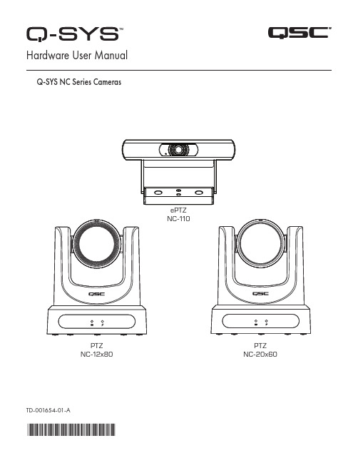
TD-001654-01-A*TD-001654-01*ePTZ NC-110PTZ NC-12x80PTZNC-20x60 Hardware User ManualQ-SYS NC Series CamerasEXPLANATION OF TERMS AND SYMBOLSThe term “WARNING!” indicates instructions regarding personal safety. If the instructions are not followed, the result may be bodily injury or death.The term “CAUTION!” indicates instructions regarding possible damage to physical equipment. If these instructions are not followed, it may result in damage to the equipment that may not be covered under the warranty.The term “IMPORTANT!” indicates instructions or information that are vital to the successful completion of the procedure.The term "NOTE" is used to indicate additional useful information.The intent of the lightning flash with an arrowhead symbol within an equilateral triangle is to alert the user to the presence of un-insulated "dangerous" voltage within the product's enclosure that may be of sufficient magnitude to constitute a risk of electric shock to humans.The intent of the exclamation point within an equilateral triangle is to alert the user to the presence of important safety,operating, and maintenance instructions in this manual.IMPORTANT SAFETY INSTRUCTIONS1. Read these instructions.2. Keep these instructions.3. Heed all warnings.4. Follow all instructions.5. Install in accordance with the manufacturer's instructions.6. Refer all servicing to qualified service personnel.7. Adhere to all applicable local codes.Maintenance and RepairsWARNING!: Advanced technology, e.g., the use of modern materials and powerful electronics, requires specially adapted maintenance and repair methods. To avoid the danger of subsequent damage to the apparatus, injuries to persons, and/or the creation of additional safety hazards, all maintenance or repair work on the apparatus should be performed only by a QSC authorized service station or an authorized QSC International Distributor. QSC is not responsible for any injury, harm, or related damages arising from any failure of the customer, owner, or user of the apparatus to facilitate those repairs. FCC StatementNote: This equipment has been tested and found to comply with the limits for a Class A digital device, pursuant to Part 15 of the FCC Rules.These limits are designed to provide reasonable protection against harmful interference when the equipment is operated in a commercial environment. This equipment generates, uses, and can radiate radio frequency energy and, if not installed and used in accordance with the instruction manual, may cause harmful interference to radio communications. Operation of this equipment in a residential area is likely to cause harmful interference in which case the user will be required to correct the interference at his own expense.Expected Product Life Cycle: 10 years, Storage Temperature range: –-20°C to +60°C, Relative Humidity: range of 5 —85% RH non-condensing.WarrantyFor a copy of the QSC Limited Warranty, visit the QSC, LLC., website at .RoHS StatementThe QSC Q-SYS NC Series: NC-110, NC-12x80, and NC-20x60 are in compliance with European Directive 2015/863/EU – Restriction of Hazardous Substances (RoHS2).What's in the BoxNC-12x80, NC-20x60 PTZ CamerasNC-110 ePTZ CameraIntroductionThe QSC Q-SYS™ NC Series comprises three camera models: NC-12x80, NC-20x60, and NC-110. These cameras send IP streams across a Q-LAN network to certain Q-SYS Core processors and peripherals, which bridge this IP signal to a USB signal for host computers to use in software applications.Connections and Controls (NC-12x80 and NC-20x60 PTZ) Front Panel1. Status LED (Green)• Off indicates the camera is in standby mode; network streams are off.• On indicates the camera is streaming video over the network.• Blinking indicates the ID mode is on.2. Power LED (Blue)• On indicates the camera has power applied.• Off indicates the camera has no power applied.Connections and Controls (NC-12x80 and NC-20x60 PTZ) (continued)Rear Panel56781. Product Label• Identifies product model: NC-12x80 or NC-20x60• Identifies the product serial number • Identifies the product MAC address2. ID Button: Press to identify this product in Q-SYS Designer Software and Q-SYS Configurator. The green STATUS LED on the frontpanel blinks when in ID mode. Press again to turn off.3. Factory Reset pin-hole: Use a paperclip or similarly sized object to insert. Press and hold the reset button for 5 seconds. This resetsall parameters to the factory defaults.4. Kensington™ Lock Slot: for use with a security cable (not supplied).5. DC 12 V: Connect an external power supply (not included). Supply must be rated at 12VDC 1A, EIAJ-04, center pin positive,outside barrel negative. Use only a class 2/LPS power supply.6. LAN/PoE: RJ-45 connector for Q-SYS Gigabit Ethernet and Power over Ethernet. Cat5e cabling or better required.7. 3G-SDI: 3G-SDI output via various video formats. Video formats can be changed via Q-SYS Designer Software or a Q-SYS UserControl Interface (UCI). Maximum video format is 1080p60.8. HDMI: HDMI® 1.4b output via various video formats. Video formats can be changed via Q-SYS Designer Software or a Q-SYSUCI. Maximum video format is 4K30. Note: NC Series PTZ Cameras support the usage of either HDMI or SDI, but not both simultaneously.Installation — NC-12x80 & NC-20x60 PTZInstall the Wall Mount Bracket1. Select a location on the wall or other vertical surface where the camera is tobe mounted. Make sure the surface is strong enough to hold the weight of the camera and bracket.2. Use the short side (1) of the bracket as a template to mark the location of thefour mounting holes (2) onto the wall.3. If the camera cables are installed inside the wall, run the cables through thelarge hole (3) in the short side of the bracket.4. Using appropriate screws (4), as necessary, attach the bracket to the wall.Tighten the attaching hardware. (Screws not supplied.)Bottom plate of Camera Mount the Camera on the Wall Bracket1. Align hole A on the bottom of the camera with the alignment pin A on thewall bracket. Place the camera onto the bracket so the alignment pin isinserted into the alignment hole on the camera and the rubber feet (C) on the bottom of the camera are inserted into the two slots (C).2. Install the larger screw (B) up through the wall bracket into the threaded holeon the bottom of the camera. Use a Phillips screwdriver to loosely tighten the screw.3. Install three smaller screws D, E, and F up through the wall bracket into thebottom of the camera. Tighten the screws using a Phillips screwdriver. 4. Tighten the larger screw installed earlier.5. If the camera cables are not installed in the wall, run the cables up throughthe oval hole (5) in the longer part of the bracket.6. Attach the cables to the appropriate connectors on the back of the cameraper installation requirements.7. Secure the cables to the bracket so that there is no strain placed on theconnectors.Connections and Controls (NC-110 ePTZ)Front Panel1. LED• Blinking Green: ID Mode• Solid Blue: Power On; Not Streaming• Solid Green: Streaming• Off: Camera is in Privacy Mode2. Included Camera Mount: This product can be configured for monitor-mounting or surface-mounting.3. Surface Mounting Screw Holes4. Universal Mounting Adapter: This can be used when connecting the NC-110 to a different mount.Rear Panel1. Factory Reset Pinhole: Use a paperclip or similarly sized object to insert. Press and hold the reset button for 5 seconds. This resetsall parameters to the factory defaults.2. ID Button: Press to identify this product in Q-SYS Designer and Configurator. The STATUS LED on the front panel blinks green whenin ID mode. Press again to turn off.3. LAN/PoE: RJ-45 connector for Q-SYS Gigabit Ethernet and Power over Ethernet. Cat5e cabling or better required.Installation (NC-110 ePTZ)Mounting Above a MonitorBend the bracket at the indicated pivot points shown to allow the optimal fit to the selected monitor. Mounting to a WallUsing the Existing Bracket for a Third-Party Mount1/4-20 UNC ThreadAttach the third-party mount to one of the 1 /4 -20 mounting holes on the included bracket. Removing the Existing Bracket for a Third-Party Mount1. On the bottom side of the camera, remove the two screws on the bracket.Remove 2 x Screws2.Slide the bracket off the camera.3. Mount the camera to the third-party mount.// DO NOT REMOVE \\Screws in block or camera1/4-20 UNC ThreadUse on various camera mounting bracketsInstalling Privacy Cover1. Peel adhesive.2. Center and attach to top of camera.3. Press firmly to affix adhesive.Dimension Drawings NC-12x80 & NC-20x60 PTZPTZ With Lens CapNC-110 ePTZQSC Self Help PortalRead knowledge base articles and discussions, download software and firmware, view product documents and training videos, and create support cases.https:///selfhelpportal/s/Customer SupportRefer to the Contact Us page on the QSC website for Technical Support and Customer Care, including their phone numbers and hours of operation.https:///contact-us/© 2021 QSC, LLC. All rights reserved. QSC, the QSC logo, Q-SYS, and the Q-SYS logo are registered trademarks of QSC, LLC, in the U.S. Patent and Trademark office and other countries. Q-LAN and Q-SYS Designer are trademarks of QSC, LLC. Patents may apply or be pending.All other trademarks are the property of their respective owners.。
Cisco Nexus 7700平台电源模块数据参数说明书

Data SheetCisco Nexus 7700 Platform Power SuppliesThe Cisco Nexus® 7700 platform switches are the latest extension to the modular Cisco Nexus 7000 Series Switches. The Cisco Nexus 7700 switches have operational and feature consistency with the existing Cisco Nexus 7000 Series Switches, using a common system architecture, the same application-specific integrated circuit (ASIC) technology, and the same proven Cisco® NX-OS Software releases.The Cisco Nexus 7700 AC and DC power supply modules (Figures 1 and 2) deliver fault tolerance, high efficiency, load sharing, and hot-swappable power features to the Cisco Nexus 7700 switches. The Cisco Nexus 7700 switches use 3.0-kilowatt (kW) power supplies that are 90 percent efficient or greater, so less power is dissipated as heat, and more power is available to the system to use than with typical power supplies. The high-efficiency 3.0-kW power supplies allow a smaller power configuration and provide flexible power provisioning.The maximum output for the 3.0-kW AC power supplies is 1400 or 3000 watts (W) if input power is 110 or 220 VAC respectively, and the dual input 3.0-kW DC power scale is 1500 or 3000W if one or two inputs respectively are active. Both the AC and DC versions support multiple system-level redundancy options for greater availability. Designed to address high-availability requirements, the power supplies incorporate internal component-level monitoring, temperature sensors, and intelligent remote-management capabilities.The power supplies are fully hot swappable, helping ensure no system interruption during installation or upgrades. They are fitted at the bottom front of the Cisco Nexus 7700 chassis, allowing installation and removal without disturbing the network cabling of the I/O modules.Figure 1. Cisco Nexus 7700 3.0-kW AC Power Supply ModuleFigure 2. Cisco Nexus 7700 3.0-kW DC Power Supply ModuleCisco Nexus 7700 3.0-kW AC Power SupplyThe 3.0-kW AC power supply module for the Cisco Nexus 7700 switch is a single 20-ampere (A) AC input power supply. Connection to high line nominal voltage (220 VAC) will produce a power output of 3000W. Connection to low line nominal voltage (110 VAC) will produce a power output of 1400W. Table 1 shows the available power output for the input options.Table 1. Available Output Based on Input PowerCisco Nexus 7700 3.0-kW DC Power SupplyThe 3.0-kW DC power supply has two isolated input stages, each delivering up to 1500W of output power. Each stage uses a -48V DC connection. The power supply will deliver 1500W when only one input is active and 3000W when two inputs are active.Table 2 shows the available power output for the input options.Table 2. Available Output Based on Input PowerFigure 3 shows the connections to the power supply inputs.Figure 3. Cisco Nexus 7700 3.0-kW DC Power Supply Module Connections and Power RatingsCisco Nexus 7700 Platform Power Supply RedundancyThe power supplies on the Cisco Nexus 7700 chassis provide multiple load sharing and fault tolerance and are hot swappable. A maximum of 2 power supplies are supported on the Cisco Nexus 7700 2-Slot Switch, a maximum of 4 power supplies are supported on the Cisco Nexus 7700 6-Slot Switch, a maximum of 8 power supplies are supported on the Cisco Nexus 7700 10-Slot Switch, and a maximum of 16 power supplies are supported on the Cisco Nexus 7700 18-Slot Switch. The 2, 4, 8, and 16 power supply bays for the 6-slot, 10-slot, and 18-slot Cisco Nexus 7700 platform chassis, respectively, are designed for redundancy and future growth.Use of multiple smaller power supplies provides flexible power provisioning and redundancy in the event of power supply failure. These power supplies also support grid redundancy to allow for grid failure or failure of facility components such as an uninterruptible power supply (UPS) or a circuit breaker.Cisco Nexus 7700 systems can operate in four user-configurable power-redundancy modes, summarized in Table 3, to meet the redundancy needs of the environment.Table 3. Power-Redundancy ModesThe total amount of power available to the Cisco Nexus 7700 switch depends on the type of power supplies installed and the configured power supply redundancy mode. The 3.0-kW AC power supply supports operation with 110 and 220V, which results in different levels of output power for the different redundancy modes. The 3.0-kW DC power supply supports single or dual input, which results in different levels of output power for the different redundancy modes.Features and BenefitsTable 4 summarizes the features and benefits of the Cisco Nexus 7700 3.0-kW AC power supply modules.Table 4. Features and Benefits of Cisco Nexus 7700 3.0-kW AC Power Supply ModulesTable 5 summarizes the features and benefits of the Cisco Nexus 7700 3.0-kW DC power supply modules.Table 5. Features and Benefits of Cisco Nexus 7700 3.0-kW DC Power Supply ModulesProduct SpecificationsTable 6 lists product specifications for the Cisco Nexus 7700 3.0-kW AC and DC power supply modules. Table 7 lists the cable specifications for the AC unit only.Table 6. Product SpecificationsTable 7. 3.0-kW AC Power Supply Cable Specifications* The 3000W power supply operating with single 110 VAC delivers 1400W.Ordering InformationTo place an order, visit the Cisco Ordering homepage. To download software, visit the Cisco Software Center.Table 8 provides ordering information.Table 8. Ordering InformationService and SupportCisco offers a wide range of services to help accelerate your success in deploying and optimizing the Cisco Nexus7700 switches in your data center. Cisco’s innovative services are delivered through a unique combination ofpeople, processes, tools, and partners and are focused on helping you increase operating efficiency and improveyour data center network. Cisco Advanced Services uses an architecture-led approach to help you align your datacenter infrastructure with your business goals and achieve long-term value. Cisco SMARTnet® Service helps youresolve mission-critical problems with direct access at any time to Cisco network experts and award-winningresources. With this service, you can take advantage of the Cisco Smart Call Home service capability, which offersproactive diagnostics and real-time alerts on your Cisco Nexus 7700 switches. Spanning the entire networklifecycle, Cisco services help increase investment protection, optimize network operations, provide migrationsupport, and strengthen your IT expertise. For more information about Cisco Data Center Services, visit/go/dcservices.For More InformationFor more information about the Cisco Nexus 7700 switches, visit the product homepage at/go/nexus7000 or contact your local account representative.Printed in USA C78-729141-05 01/15。
- 1、下载文档前请自行甄别文档内容的完整性,平台不提供额外的编辑、内容补充、找答案等附加服务。
- 2、"仅部分预览"的文档,不可在线预览部分如存在完整性等问题,可反馈申请退款(可完整预览的文档不适用该条件!)。
- 3、如文档侵犯您的权益,请联系客服反馈,我们会尽快为您处理(人工客服工作时间:9:00-18:30)。
Modification Record List NO. Issue Date Modification Index 1 2012/03/05 First Edition2 2012/04/27 P6.-P.14 Revised ELECTRICAL CHARACTERISTICS Spec. P17.Revised Response Time max 45-->50msP21.Revised RELIABILITY TEST CONDITIONS3 2012/10/4 P11. Revised Connector Interface PIN & FunctionTable of ContentNO. Table of Content Page1 OVERVIEW 42 ABSOLUTE MAXIMUM RATINGS 53 ELECTRICAL CHARACTERISTICS 64 CONNECTOR INTERFACE PIN & FUNCTION 95 INTERFACE TIMING CHART 116 BLOCK DIAGRAM 147 MECHANICAL SPECIFICATION 158 OPTICAL CHARACTERISTICS 179 RELIABILITY TEST CONDITIONS 211. OVERVIEWCLAA070WP03次品 is 7” color TFT-LCD (Thin Film Transistor Liquid Crystal Display) module composed of LCD panel, LVDS driver ICs, control circuit and backlight. By applying 6 bit digital data, 800×RGB (3) ×1280, 262,144-color images are displayed on the 7” diagonal screen. general specifications are summarized in the following table:ITEM SPECIFICATIONDisplay Area 94.2(H)x150.72(V) (mm) (7-inch diagonal)Number of Pixels 800 ×3(H)×1280 (V)Pixel Pitch 0.11775(H)×0.11775(V) (mm)Color Pixel Arrangement RGB vertical stripeDisplay Mode Normally BlackNumber of Colors 262,144(6bits)(LVDS)Gamut 60%(Typ)Optimum Viewing Angle whole viewResponse Time 60ms (Max)Surface Treatment HC , Hardness:3HViewing Angle(CR>10) 85°、85° / 85°、85°(Min)Brightness 450 cd/m2 (5points, average) (Typ)Uniformity 9point:80 %(Typ.)Consumption of Power 0.5 (LCD Module Typical)/ 1.692 (Backlight Typical)Module Size 161.67(H)×104.32(V)×3.85(D) (Typ.)Module Weight 101g (Max)The LCD Products listed on this document are not suitable for use of aerospace equipment, submarinecable, and nuclear reactor control system and life support systems. If customers intend to use these LCD products for applications listed above or those not included in the "Standard" list as follows, please contact our sales in advance.Standard:Computer, Office equipment, Communication equipment, Test and Measurement equipment, Machine tool, Industrial robot, Audio and Visual equipment, Other consumer products.2. ABSOLUTE MAXIMUM RATINGSThe following are maximum value, which if exceeded, may cause faulty operation or damage to the unit.Ta=25+/-2℃ITEM SYMBOL MIN. MAX. UNIT NOTE LCD Power Voltage VDD 0 4.5 VOperation Temperature Top 0 50 ℃*1). 2). 3). 4)Storage Temperature Tstg -25 65 ℃*1). 2). 3)【Note】*1) The relative temperature and humidity range are as below sketch, 90%RH Max.(Ta≦40℃)*2) The maximum wet bulb temperature ≦39℃(Ta>40℃) and without dewing.*3) If product in environment which over the definition of the relative temperature and humidity out of range too long, it will affect visual of LCD.*4) If you operate LCD in normal temperature range, the center surface of panel should be under 50℃.3. ELECTRICAL CHARACTERISTICS(A) TFT LCDTEMSYMBOL MIN TYP MAX UNITNOTELCD Power Voltage VDD 3 3.3 3.6 V *1) LCD Power Current IDD - - - mA *2) Rush CurrentIrush--2A*4)【Note 】*1) Power Sequence :0.5 ms ≦t1≦10ms 500 ms ≦t4 0.01 ms <t2≦50 ms 200 ms ≦t5 0.01 ms <t3≦50 ms 200 ms ≦t6Vin-dip state(1)when 3.0V >Vin ≧2.7V ,td ≦10 ms.(2)when Vin <2.7V ,Vin-dip condition should as the Vin-turn-off condition.V*2) Max value is White Pattern:1280 line mode。
Circuit condition (Max.):VDD=3.3 V,f V=60 Hz,f H=51.84 kHz,f CLK=66.77 MHz*3) LVDS Signal Definite:LVDS Interface DC characteristic(VDD=3.0 to 3.6V, AVDD=8.0 to 13.5V, GND=AGND=0V, TA=-20 to +85℃)Parameter Symbol Min. Typ. Max. Unit Condition Differential input high threshold voltage RxVTH +0.2 VDifferential input low threshold voltage RxVTL -0.2 VRxVCM=1.2V Input voltage range(singled-end) RxVIN 0.7 - 1.7 VDifferential input common mode voltage RxVCOM 1 1.2 1.4 V |VID|=0.2VDifferential input impedance ZID 80 100 125 oh mDifferential input voltage |VID| 0.2 - 0.6 VFigure1. LVDS DC DiagramLVDS Interface AC characteristic(VDD=3.0 to 3.6V, AVDD=8.0 to 13.5V, GND=AGND=0V, TA=-20 to +85)℃Parameter Symbol Min. Typ. Max. Unit ConditionClock frequency RxFCLK . 66.77 - MHz Refer to input timing table for each display resolution.Input data skew margin TRSKM 500 - - ps |VID|=200mV RxVCM=1.2V RxFCLK=81MHzClock high time TLVCH - 4/(7*RxFCLK) - nsClock low time TLCVL - 3/(7*RxFCLK) - nsPLL wake-up time TenPLL - - 150 usFigure2. Relationship between VDD, LVDS clock, and internal clockFigure3. 1 cycle time of LVDS*4) Irush measure condition(B) BACK LIGHT(a.) ELECTRICAL CHARACTERISTICSTa=25℃ITEM SYMBOL MIN TYP MAX UNIT NOTE LED Driver Iuput Voltage VBL+ 3.0 3.3 5.0 VLED Driver Input Current IBL+ - 512 - mA *1) Forward Voltage VF 2.85 3 V *2)I F=19mAForward Current IF - 19 - mAPower consumption PLED - 1.692 W *2)*3)I F=19mA PWM Frequency PWM_BL 180 200 220 HzDuty ratio Dim 5 100 %(b) LED LIFE – TIMEITEM Condition min typ max UNIT NOTE LIFE TIME IF=20mA、Ta=25℃10000 x x hrs *4)(c) LED ON/OFF Sequence :0.5ms ≦ T1 ≦ 10ms10ms ≦ T2 10ms ≦ T3 0ms ≦ T4 10ms ≦ T5*1) Maximum LED Driver Input Current at 3 V Input Voltage/PWM Duty 100%.*2) Measure method :a. LED current is measured by utilizing a current meter as show below.b. System power PLED is measured at input voltage 3.3V*3) Calculator value for reference I F × V F × N = PLED*4) Life time means that estimated time to 50% degradation of initial luminous intensity.PLED10%10%90%90%PWMENT1 T2 T3 T4 T5BLVDDLEDLED_PWMLED_EN4. Connector Interface PIN & FunctionCN(Interface signal)NO. Symbol Description1 VDD Power Supply, 3.3V typ2 VDD Power Supply, 3.3V typ3 VDD Power Supply, 3.3V typ4 NC NC5 GND Ground6 RXINO- LVDS Signal(-)—channel 07 RXINO+ LVDS Signal(+)—channel 08 GND Ground9 RXINO1- LVDS Signal(-)—channel 110 RXINO1+ LVDS Signal(+)—channel 111 GND Ground12 RXINO2- LVDS Signal(-)—channel 213 RXINO2+ LVDS Signal(+)—channel 214 GND Ground15 RXCLKIN- LVDS Clock Signal(-)16 RXCLKIN+ LVDS Clock Signal(+)17 GND Ground18 NC NC19 NC NC20 GND Ground21 LVBIT(1.8V)Ground22 DITHER(1.8V)Ground23 GND Ground24 LED EN (PWM) PWM25 LVFMT(1.8V)Ground26 BIST NC27 VLED LED Power Supply , 3~5V28 VLED LED Power Supply , 3~5V29 VLED LED Power Supply , 3~5V30 VLED LED Power Supply , 3~5V31 NC NC6. BLOCK DIAGRAM7. MECHANICAL SPECIFICATION(1) Front sideThe tolerance, not show in the figure, is ±0.2mm. [Unit:mm](2) Rear sideThe tolerance, not show in the figure, is ±0.2mm [Unit :mm]8. OPTICAL CHARACTERISTICSTa=25℃,VDD=3.3V ITEM SYMBOL CONDITION MIN. TYP. MAX. UNIT NOTE Contrast Ratio CR θ=ψ﹦0° 500 700 -- -- *1) 2) Luminance (5P Average) L θ=ψ﹦0° 300 450 -- cd/m2*1) 3) Uniformity(9P) ∆L θ=ψ﹦0° 72 80 -- % *1) 3) Response Time Tr+Tf θ=ψ﹦0° -- -- 50 ms *5) Cross talk CT θ=ψ﹦0° -- -- 2.5 % *6) Horizontal Ψ80/-80 85/-85 -- °View angleView angleVertical θCR≧1080/-80 85/-85 -- °0.28 0.310 0.340W XY 0.30 0.330 0.360--TBD TBD TBDR XY TBD TBD TBD--TBD TBD TBDG XY TBD TBD TBD--TBD TBD TBDColor Temperature CoordinateB XYθ=ψ﹦0°TBD TBD TBD--ColorTemperatureCoordinateGamut θ=ψ﹦0° -- 60 -- %Gamma γGL 2.0 2.2 2.4 -- *7) Color coordinate and color gamut are measured by SRUL1R, response time is measured by TRD-100,and all the other items are measured by BM-5A (TOPCON). All these items are measured under the dark room condition (no ambient light).Measurement Condition: IL=19 mA(each LED)Definition of these measurement items is as follows:*1) Setup of Measurement EquipmentThe LCD module should be turn-on to a stable luminance level to be reached. The measurement should beexecuted after lighting Backlight for 20 minutes and in a dark room.*2) Definition of Contrast RatioCR=ON (White) Luminance/OFF (Black) Luminance*3) Definition of Luminance and Luminance uniformityCentral luminance: The white luminance is measured at the center position “1” on the screen, see Fig below.5P Luminance (AVG): The white luminance is measured at measuring points 1~5 see Fig below. 9P Uniformity: ∆L = (Lmin / Lmax) ×100% at measuring points 1 & 6~13 see fig below.*4) Definition of view angle(θ,ψ)*5) Definition of response timeWhiteUpper(+) Right(+)Left(-)Gate Drive Side Lower(-)*6) Crosstalk Modulation Ratio:CT=∣Y B -Y A ∣ / Y A×× 100%Y A 、Y B measure position and definitionY A means luminance at gray level 31(exclude gray level 0 pattern) Y B means luminance at gray level 31(include gray level 0 pattern)*7) Definition Gamma (VESA)Based on Customer Sample, take the average value as a standard center value and the variation range ofgamma value caused by loop voltage error should be between +/- 0.2. the bellow figure shows how to obtainthe gamma curve and γ (from gray level: 0、4、8-----60、63).LOG(9. RELIABILITY TEST CONDITIONSHigh Temp. Storage Test 80℃,240 HrsHigh Temp. Operating Test 70℃,240HrsLow Temp. Storage Test -30℃,240 HrsLow Temp. Operating Test -20℃,240 HrsHigh Temp/ High Humidity40℃,95% RH,240HrsOperating TestHigh Temp./High Humidity60℃,90% RH ,240HrsStorage TestThermal Shock Test -30℃(0.5 Hr)~80℃(0.5 Hr), 56 CyclesLow Air Pressure Test 533mbar(100mbar/min ramp),"-40C~55℃"(1C/min ramp)and 2hrs per each temperature FPC Bending test Bending degree is 180, bending 30 times and the bendingradius is 1.0mmFPC Insert/Remove test 30 times FPC insert/removeShock Test 980m/s2,Action time: 6ms, Time: 3 times for eachdirection, Direction:+/-X, +/-Y, +/-ZESD 150pF、330Ω、contact+-8KV/ Air+-15KV, NO DAMAGE Package Vibration test Frequency range: 10-55Hz, 1.2Grms, swep time: 1minute, test period: 2 hours for each direction of X, Y, Z Package Drop test Height: 60cm, 1 corner, 3 edges, 6 surfaces: 1 time foreach direction(1) MTBF without B/L : 200,000 Hrs(min) lifetime.(2) Judgment standardThe judgment of the above test should be made as follow:Pass:Normal display image with no obvious non-uniformity and no line defect.Partial transformation of the module parts should be ignored.Fail:No display image, obvious non-uniformity, or line defects.10. WARRANTY10.1 The period is within 3 month since the date of shipping out under normal usingand storage conditions.10.2 The warranty will be avoided in case of defect induced by customer。