BasebandTranceiver03Spring802_11a
Grandstream Networks, Inc. GWN7600LR 企业级 802.11ac
Grandstream Networks,Inc. GWN7600LR企业级802.11ac Wave-2室外型长距离WiFi接入点用户手册图4:GWN7600LR水平安装保修如果您购买自经销商,请直接联系经销商更换,维修或退货。
如果您直接购于潮流网络公司,请联系潮流技术支持团队,取得退货许可号码(RMA)后退货。
潮流网络科技公司保留在不做预先通知的情况下修改售后服务细则的权利。
图12:GWN7600Web页面登录页面访问Web页面:1.将电脑连到GWN7600LR所在的局域网中。
2.确保设备已经上电。
3.打开Web浏览器,并用“发现GWN7600LR”章节中介绍的方式输入设备MAC地址或以下形式输入Web页面 面 https://IP_Address。
4.输入管理员的账号和密码登录WEB配置页面,默认的管理员账号和密码均为“admin”。
Web页面语言当前GWN7600LR系列Web页面支持英语和简体中文。
用户可以在登录之前或之后在WEB用户登录界面的右上角选择显示的语言。
图8:GWN7600LR Web页面语言(登录页面)概览页面概览页面是成功登录GWN7600LR的Web界面后显示的第一页。
概览页面提供了以仪表板样式显示的GWN7600LR信息的总体视图,便于监控。
图10:概览页面用户可以点击进入接入显示连接的客户端的总数,击进入客户页面了解更多选项。
AP的客户端的数目或者组合上用户可以点击进入AP的客户端的数目或者组合上行和下行的数据使用来分类列表。
用户可以点击进入网络组页面以获得显示热门客户列表,击进入客户页面了解更多选项。
用户可以单击以弹出警报图11:应用修改应用修改,或点击图16:应用成功图14:登录页面在恢复出厂时,默认选中“以主接入点登录”,在输入管理员的用户名和密码后点击“登录”。
--------------------------------------------------------------------------------------------------------------------------------------------警告:“以主接入点登录”选项将禁止GWN7600LR接入点与其他主GWN76xx配对,并且只能作为主接入点控制器工作。
Arista O-105E 2x2 MIMO 802.11ac Wave 2 室外接入点说明书
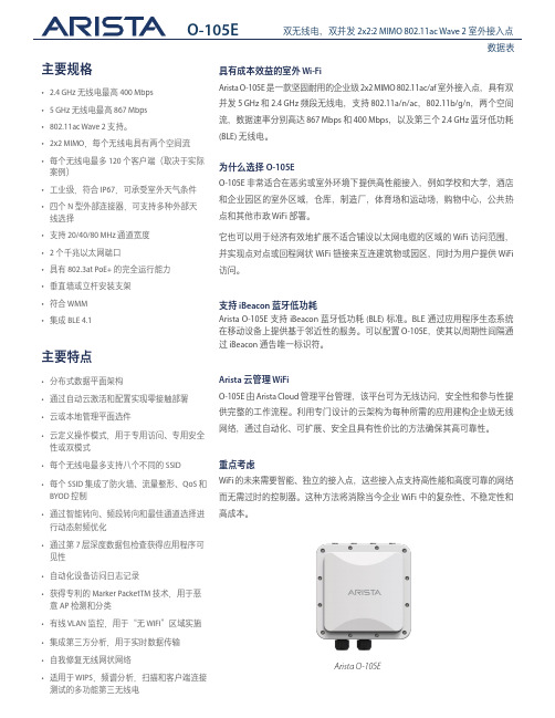
数据表主要规格主要特点• 2.4 GHz 无线电最高 400 Mbps • 5 GHz 无线电最高 867 Mbps • 802.11ac Wave 2 支持。
• 2x2 MIMO ,每个无线电具有两个空间流• 每个无线电最多 120 个客户端(取决于实际案例)• 工业级,符合 IP67,可承受室外天气条件• 四个 N 型外部连接器,可支持多种外部天线选择• 支持 20/40/80 MHz 通道宽度• 2 个千兆以太网端口• 具有 802.3at PoE+ 的完全运行能力• 垂直墙或立杆安装支架• 符合 WMM • 集成BLE 4.1• 分布式数据平面架构• 通过自动云激活和配置实现零接触部署• 云或本地管理平面选件• 云定义操作模式,用于专用访问、专用安全性或双模式• 每个无线电最多支持八个不同的 SSID • 每个 SSID 集成了防火墙、流量整形、QoS 和 BYOD 控制• 通过智能转向、频段转向和最佳通道选择进行动态射频优化• 通过第 7 层深度数据包检查获得应用程序可见性• 自动化设备访问日志记录• 获得专利的 Marker PacketTM 技术,用于恶意 AP 检测和分类• 有线 VLAN 监控,用于“无 WiFi ”区域实施 • 集成第三方分析,用于实时数据传输• 自我修复无线网状网络• 适用于 WIPS ,频谱分析,扫描和客户端连接测试的多功能第三无线电具有成本效益的室外 Wi-FiArista O-105E 是一款坚固耐用的企业级 2x2 MIMO 802.11ac/af 室外接入点,具有双并发 5 GHz 和 2.4 GHz 频段无线电,支持 802.11a/n/ac ,802.11b/g/n ,两个空间流,数据速率分别高达 867 Mbps 和 400 Mbps ,以及第三个 2.4 GHz 蓝牙低功耗 (BLE) 无线电。
为什么选择 O-105EO-105E 非常适合在恶劣或室外环境下提供高性能接入,例如学校和大学,酒店和企业园区的室外区域,仓库,制造厂,体育场和运动场,购物中心,公共热点和其他市政 WiFi 部署。
华为 AP4050DE-M 802.11ac Wave 2 无线路由器说明书

Huawei AP4050DE-M Access Point DatasheetProduct OverviewHuawei AP4050DE-M is an 802.11ac Wave 2 access point (AP) that supports 2x2 MIMO and two spatial streams. It provides comprehensive service support capabilities and features high reliability, high security, simple network deployment, automatic AC discovery and configuration, and real-time management and maintenance, which meets network deployment requirements. The AP has built-in smart antennas and supports smooth evolution from 802.11n to 802.11ac and can provide gigabit access for wireless users. The AP4050DE-M is applicable to commercial chains, medical, warehousing, manufacturing, and logistics environments.AP4050DE-M●802.11ac Wave 2 standards compliance, MU-MIMO (2SU-2MU), delivering services simultaneously on 2.4G and 5G radios, at a rate of up to 400 Mbit/s at 2.4 GHz, 867 Mbit/s Mbit/s at 5 GHz, and 1.267 Gbit/s for the device.●Smart antenna array technology enables targeted signal coverage for mobile terminals, reduces interferences, and improves signal quality. Additionally, it implements millisecond-level switchover as STAs move.●Built-in Bluetooth 5.0, increasing the working distance and working with eSight to accurately locate Bluetooth terminals.●Supports the Fat, Fit, and cloud modes and enables Huawei cloud-based management platform to manage and operate APs and services on the APs, reducing network O&M costsFeature DescriptionsSmart antenna array technology●The AP integrates smart antenna and implicit beamforming technologies to implement more precise user detection, suppress interference, and improve signal quality, enabling users to have a seamless, smooth wireless network experience.MU-MIMO●The AP supports MU-MIMO to send data to multiple STAs at the same time (currently, most 802.11n or 802.11ac Wave 1 APs can only send data to one STA simultaneously).GE access●The APs support the 80-MHz bandwidth mode. Frequency bandwidth increase brings extended channels and more sub-carriers for data transmission, and a 2.16-fold rate increase. Support for High Quadrature Amplitude Modulation (HQAM) at 256-QAM increases the 5 GHz radio rate to 867 Mbit/s and the AP rate to 1.267 Gbit/s.Cloud-based management●Huawei Cloud Managed Network (CMN) Solution consists of the cloud management platform and a full range of cloud managed network devices. The cloud management platform provides various functions including management of APs, tenants, applications, and licenses, network planning and optimization, device monitoring, network service configuration, and value-added services.High Density Boost technologyHuawei uses the following technologies to address challenges in high-density scenarios, including access problems, data congestion, and poor roaming experience:SmartRadio for air interface optimization●Load balancing during smart roaming: The load balancing algorithm can work during smart roaming for load balancing detection among APs on the network after STA roaming to adjust the STA load on each AP, improving network stability.●Intelligent DFA technology: The dynamic frequency assignment (DFA) algorithm is used to automatically detect adjacent-channel and co-channel interference, and identify any 2.4 GHz redundant radio. Through automatic inter-AP negotiation, the redundant radio is automatically switched to another mode (dual-5G AP models support 2.4G-to-5G switchover) or is disabled to reduce 2.4 GHz co-channel interference and increase the system capacity.●Intelligent conflict optimization technology: The dynamic enhanced distributed channel access (EDCA) and airtime scheduling algorithms are used to schedule the channel occupation time and service priority of each user. This ensures that each user is assigned relatively equal time for using channel resources and user services are scheduled in an orderly manner, improving service processing efficiency and user experience.5G-prior access (Band steering)●The APs support both 2.4G and 5G frequency bands. The 5G-prior access function enables an AP to steer STAs to the 5 GHz frequency band first, which reduces load and interference on the 2.4 GHz frequency band, improving the user experience.Wired and wireless dual security guarantee●To ensure data security, Huawei APs integrate wired and wireless security measures and provide comprehensive security protection.Authentication and encryption for wireless access●The APs support WEP, WPA/WPA2–PSK, WPA/WPA2–PPSK, WPA/WPA2–802.1X, WPA3-SAE, WPA3–802.1X,and WAPI authentication/encryption modes to ensure security of the wireless network. The authentication mechanism is used to authenticate user identities so that only authorized users can access network resources. The encryption mechanism is used to encrypt data transmitted over wireless links to ensure that the data can only be received and parsed by expected users.Analysis on non-Wi-Fi interference sources●Huawei APs can analyze the spectrum of non-Wi-Fi interference sources and identify them, including baby monitors, Bluetooth devices, digital cordless phones (at 2.4 GHz frequency band only), wireless audio transmitters (at both the 2.4 GHz and 5 GHz frequency bands), wireless game controllers, and microwave ovens. Coupled with Huawei eSight, the precise locations of the interference sources can be detected, and the spectrum of them displayed, enabling the administrator to remove the interference in a timely manner.Rogue device monitoring●Huawei APs support WIDS/WIPS, and can monitor, identify, defend, counter, and perform refined management on the rogue devices, to provide security guarantees for air interface environment and wireless data transmission.AP access authentication and encryption●The AP access control ensures validity of APs. The CAPWAP link protection and DTLS encryption provide security assurance, improving data transmission security between the AP and the AC.Automatic radio calibration●Automatic radio calibration allows an AP to collect signal strength and channel parameters of surrounding APs and generate AP topology according to the collected data. Based on interference from authorized APs, rogue APs, and non-Wi-Fi interference sources, each AP automatically adjusts its transmit power and working channel to make the network operate at the optimal performance. In this way, network reliability and user experience are improved.Automatic application identificationHuawei APs support smart application control technology and can implement visualized control on Layer 4 to Layer 7 applications.Traffic identification●Coupled with Huawei ACs, the APs can identify over 1600 common applications in various office scenarios. Based on the identification results, policy control can be implemented on user services, including priority adjustment, scheduling, blocking, and rate limiting to ensure efficient bandwidth resource use and improve quality of key services.Traffic statistics collection●Traffic statistics of each application can be collected globally, by SSID, or by user, enabling the network administrator to know application use status on the network. The network administrator or operator can implement visualized control on service applications on smart terminals to enhance security and ensure effective bandwidth control.Basic SpecificationsFat/Fit AP modeCloud-based management modeTechnical SpecificationsStandards complianceAntennas Pattern2.4G (PHI=0) 2.4G (PHI=90)5G (PHI=0)5G (PHI=90)Ordering InformationMore InformationFor more information about Huawei WLAN products, visit or contact us in the following ways: ●Global service hotline: /en/service-hotline●Logging in to the Huawei Enterprise technical support web: /enterprise/●Sending an email to the customer service mailbox: ********************Copyright © Huawei Technologies Co., Ltd. 2020. All rights reserved.No part of this document may be reproduced or transmitted in any form or by any means without prior written consent of Huawei Technologies Co., Ltd.Trademarks and Permissionsand other Huawei trademarks are trademarks of Huawei Technologies Co., Ltd.All other trademarks and trade names mentioned in this document are the property of their respective holders.NoticeThe purchased products, services and features are stipulated by the contract made between Huawei and the customer. All or part of the products, services and features described in this document may not be within the purchase scope or the usage scope. Unless otherwise specified in the contract, all statements, information, and recommendations in this document are provided "AS IS" without warranties, guarantees or representations of any kind, either express or implied.The information in this document is subject to change without notice. Every effort has been made in the preparation of this document to ensure accuracy of the contents, but all statements, information, and recommendations in this document do not constitute a warranty of any kind, express or implied.Huawei Technologies Co., Ltd.Address:Huawei Industrial Base Bantian, Longgang Shenzhen 518129 People's Republic of ChinaWebsite:。
JetWave 4020 4020E系列工业级802.11ac + 802.11n 2.4G WIF
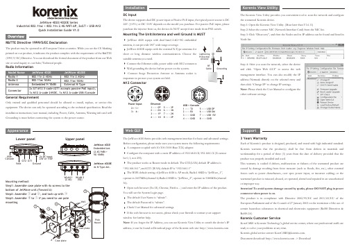
AppearanceJetWave 4020/4020E SeriesIndustrial 802.11ac + 802.11n 2.4G WIFI AP, 2xGT + USB M12Quick Installation Guide V1.0R&TTE Directive 1999/5/EC DeclarationThe product may be operated in all European Union countries. While you see the CE Marking printed on our product, it indicates the product complies with the requirement of the R&TTE (1995/5/EC) Directive. You can download the formal document of the product from our Web site or send inquiry to our Sales/Technical people.Only trained and qualified personnel should be allowed to install, replace, or service this equipment. The device can only be operated according to the technical specification. Read the installation instructions/user manual, including Power, Cable, Antenna, Warning info and well Grounding is must before connecting the system to the power source.DC InputThe device supports dual DC power input or Passive PoE input, the typical power source is DC 24V (±15%) or DC 110V depends on the model you purchase. For passive PoE input, please purchase the injector from us, the device do NOT accept force mode from PSE switch.The Korenix View Utility provides you convenient tool to scan the network and configure the connected Korenix device.Step 1: Open the Korenix View Utility. (Must later than V1.6.11)Step 2: Select the correct NIC (Network Interface Card) from the NIC list.Step 3: Click “Discovery”, and then the Nodes and its IP address can be found and listed in Node list.Step 4: After you scan the network, select the deviceand click “Open Web GUI” to access the web management interface. You can also modify the IP address/Netmask directly on the selected entry and then click “Change IP“ to change IP settings.Note: Please check the User Manual to configure theother software settings.3 Years WarrantyEach of Korenix’s product is designed, produced, and tested with high industrial standard. Korenix warrants that the product(s) shall be free from defects in materials and workmanship for a period of three (3) years from the date of delivery provided that the product was properly installed and used.This warranty is voided if defects, malfunctions or failures of the warranted product are caused by damage resulting from force measure (such as floods, fire, etc.), other external forces such as power disturbances, over spec power input, or incorrect cabling; or the warranted product is misused, abused, or operated, altered and repaired in an unauthorized or improper way.Attention! To avoid system damage caused by sparks, please DO NOT plug in power connector when power is on.The product is in compliance with Directive 2002/95/EC and 2011/65/EU of the European Parliament and of the Council of 27 January 2003 on the restriction of the use of certain hazardous substances in electrical and electronics equipment (RoHS Directives &RoHS 2.0)Korenix Customer ServiceKoreCARE is Korenix Technology's global service center, where our professional staffs are ready to solve your problems at any time.Korenixglobalservicecenter:********************.Document download: -> DownloadSupportThe JetWave 4020 Series provides web management interface for basic and advanced settings. Before configuration, please make sure your system meets the following requirements:A computer coupled with 10/100/1000 Base-T(X) adapter.Configure the computer with a static IP address of 192.168.10.X/192.168.1.X (X cannotbe 0, 1, nor 255).The product works as Router mode in default. The GT2(LAN) default IP address is“192.168.10.1”, and GT1 (WAN) default IP is “192.168.1.1”The WIFI default setting of JetWave 4020 is AP mode, Radio1 SSID is “JetWave_1”,operate in 2437MHz(channel 6).Radio2 SSID is “JetWave_2”, operate in 5180MHz(channel 36).Open web browser (Ex: IE, Chrome, Firefox…) and enter the IP address of the product.You will see the System Login page.The default User Name is “admin”.The default Password is “admin”.Check User Manual for advanced settings.If the web browser is not access, please check your firewall or contact your supportwindow for further help.Note: If you forget the IP Address, you can use Korenix View Utility to search the device’s IPaddress, it can be found at Download page of the Korenix web site: Web GUIRadio InformationEthernet 1 ----- 0P 2 ----- 0N 3 ----- 1P 4 ----- 1N5 ----- 3P6 ----- 3N7 ----- 2N8 ----- 2P23758461USB + Console1 ----- TX2 ----- RX3 ----- GND4 ----- GND5 ----- USB DP6 ----- USB DM7 ----- USB +5V8 ----- GND Power Input 2:+ 1:+ 3:- 4:-Upper panelLower panelWLAN 1(2.4G)WLAN 2(5G)JetWave 4020Embedded Ant.(2.4G 9dBi + 5G 10dBi)JetWave 4020E 4x N-Type Ant.GroundingRF CableLightening Protection ArrestorMounting method:Step2: Assemble Step3: Assemble mounting Case plateJetWave 4020 equips with dual band 2.4G+5G embeddedantenna, it can provide 180owide range coverage.JetWave 4020E equips with the external N-Type antennas forshort or long distance wireless communication. Choose the suitable antenna you need.Connect the Ethernet cable, power cable with M12 connector. Well grounding the device before power on the system.Connect Surge Protection Arrestor at Antenna socket isimportant to protect your system on field.M12 ConnectorMounting The Unit/Antenna and well Ground is MUSTR&TTE 指令1999/5/EC 宣告该产品可在所有欧盟国家进行操作。
上海崭适通讯工程有限公司11AC产品和11N产品概述

802.11ac 和802.11N 使用技术文章分析一、概述由于多数的802.11n设备是为2.4GHz频段设计,2.4GHz本身的可用信道较少,同时还有其它工作于2.4GHz 频段的设备(例如蓝牙,微波炉、无线监视摄像机等)的干扰,即使在双空间流40Mhz频宽下其连接速率能达到300Mbps,但是实际网络环境中,由于相互的信道冲突等原因,其实际吞吐并不高,用户体验差。
802.11ac 是专门为5GHz频段设计,特有的新射频特点,能够将现有的无线局域网的性能吞吐提高到可以与有线千兆级网络相媲美的程度。
802.11ac作为IEEE 无线技术的新标准,它借鉴了802.11n的各种优点并进一步优化,除了最明显的高吞吐特点外,不仅可以很好地兼容802.11a/n的设备,同时还提升了多项用户体验。
在802.11ac的网络中,每个无线接入点可以接纳更多的客户端,为每个并行的业务流提供更多的带宽,同时具有更低时延更省电的优点。
二、802.11ac 主要技术特征由于802.11n在MAC层已经很优异了,因此802.11ac在MAC层上的改进并不多,主要通过PHY层来提升其基础速率。
PHY层的改进1、更密的调制模式802.11ac继续采用802.11a中OFDM调制方法,但是将阶数从802.11n中的64阶提高到了256阶。
256-QAM 使得每个子载波的数据比特数从6提到8,从而使得速率增加了将近33%。
由于256-QAM对干扰更加敏感,适合于信噪比高的环境,因此256阶正交调幅主要在64阶正交调幅已经可靠覆盖的范围内才有帮助。
虽然256-QAM提供了更高的速率,但是它并没有增加有效的覆盖距离。
例外,不像802.11n中那样可以采用非等星座调制,在802.11ac中,当多条流同时发送时,每条流都必须采用同等大小的星座。
而前者对于多空间流特别是波束成形来说却非常有益。
2、更宽的信道带宽由于5GHZ频段可以提供更多的信道和更宽的频宽,802.11ac 将信道频宽从802.11n的20MHZ和40MHZ提升到了80MHZ,甚至是160MHZ。
H3C 802.11n无线网络工堪案例讲解

17
低密度类宿舍环境
环境特点:走廊两侧有房间,走廊墙壁较厚的环境。
窗
门 楼道 楼道
采用天线入室方式,每个天线直接覆盖本房间内部,并采用美 化天线,对用户丌会造成心理压力。 其他用户/房间密集区域也可借鉴。
18
低密度类宿舍环境(配置)
×3 ×3
48 120 140
0404A08X
CAB-RF-10m(2*NSM+RG8/U)
射频电缆-10m-50ohm-N50直公-(COAX-RG8/U)N50直公
235
2,000
4
2
2701A00X ANT-2503C-M2
2.4GHz(3dBi),定吐迷你美化天线,N型×1|RP-SMA×1, 室内,天花板|墙壁|2.4GHz(3dBi)
MIMO类型 1x1 2x2 3x3
空间流数(Stream) 空间传输率 1 2 2 150M 300M 300M
最大整机能力 150M 600M 600M
3x3
3
450M
900M
千兆 加速
3-Streams 11n MIMO实现450 Mbps传输速率
整机千兆接入能力,相比传统11a/g 10倍的速率提升
3.47 Gbit/s to 4-antenna STA 1.73 Gbit/s to 2-antenna STA 867 Mbit/s to each 1-antenna STA
6.93 Gbit/s
1.73 Gbit/s to each STA
6.93 Gbit/s
2
4-antenna AP, 4 1antenna STAs, 160MHz Handheld (MU-MIMO) 8-antenna AP, 160MHz (MU-MIMO) Digital TV, Set-top Box, -- 1 4-antenna STA Tablet, Laptop, PC, -- 1 2-antenna STA Handheld -- 2 1-antenna STAs 8-antenna AP, 4 2Digital TV, Tablet, antenna STAs, 160MHz Laptop, PC (MU-MIMO)
罗翔网络WiFly GSX 802.11 b g无线局域网模块数据手册说明书

WiFly GSX 802.11 b/g Wireless LAN ModuleFeatures•Qualified 2.4GHz IEEE 802.11b/g transceiver •High throughput, 1Mbps sustained data ratewith TCP/IP and WPA2•Ultra-low power - 4uA sleep, 40mA Rx,210mA Tx (max)•Small, compact surface mount module•On board ceramic chip antenna and U.FL connector for external antenna•8 Mbit flash memory and 128 KB RAM•UART hardware interface•10 general purpose digital I/O•8 analog sensor interfaces•Real-time clock for wakeup and time stamping •Accepts 3.3V regulated or 2-3V battery•Supports Adhoc connections•On board ECOS -OS, TCP/IP stacks•Wi-Fi Alliance certified for WPA2-PSK•FCC / CE/ ICS certified and RoHS compliant.•Industrial (RN-131G) and commercial(RN-131C ) grade temperature options Applications•Remote equipment monitoring•Telemetry••Home Automation•Medical device monitoringDescriptionThe WiFly GSX module is a stand alone, embedded wireless 802.11 networking module. Because of its small form factor and extremely low power consumption, the RN-131G is perfect for mobile wireless applications such as asset monitoring, GPS tracking and battery sensors. The WiFly GSX module incorporates a 2.4GHz radio, processor, TCP/IP stack, real-time clock, crypto accelerator, power management and analog sensor interfaces. This complete solution is preloaded with software to simplify integration and minimizes development of your application. In the simplest configuration the hardware only requires four connections (PWR, TX, RX, GND) to create a wireless data connection. Additionally, the sensor interface provides temperature, audio, motion, acceleration and other analog data without requiring additional hardware. The WiFly GSX module is programmed and controlled with a simple ASCII command language. Once the WiFly GSX is setup it can scan to find an access point, associate, authenticate and connect over any WifI network.Block DiagramOverview•Host Data Rate u p to 1 Mbps for UART•Intelligent, built-in power management with programmable wakeup•Can be powered from regulated 3.3-3.7V source or 2.0-3.0V batteries•Real time clock for time stamping, auto-sleep and auto-wakeup•Configuration over UART using simple ASCII commands•Telnet configuration over WiFi•Over the air firmware upgrade (FTP)•Memory 128 KB RAM,2MB ROM, 2 KB battery-backed memory, 8 Mbit Flash.•Secure WiFi authentication WEP-128, WPA-PSK (TKIP), WPA2-PSK (AES)•Built in networking applications DHCP, UDP, DNS, ARP, ICMP, TCP, sockets•802.11 power save and roaming functionsEnvironmental ConditionsParameter RN-131G RN-131C Temperature Range (Operating) -30 o C ~ +85 o C 0 o C ~ +70 o CTemperature Range (Storage) -40o C ~ +85 o C -40o C ~ +85 o C Relative Humidity (Operating) ≤90% ≤90%Relative Humidity (Storage) ≤90% ≤90% Electrical CharacteristicsSupply Voltage Min Typ. Max. Unit Supply Voltage VDD 3.0 3.3 3.7 VDC Supply Voltage (VBATT option) 2.0 3.0 3.3 VDCPin 21 switched 3.3V output 150 ma Digital IinputInput logic HIGH VIH 2.3V VDC Input logic LOW VIL 1.0V VDC Digital Output drivePIO 4,5,6,7,8 24 ma PIO 9,10,11,12,13 8 ma Power consumptionSleep 4 uA Standby (doze) - 15 - mA Connected (idle, RX) 40 mA Connected (TX) 140 212 mAAnalog Sensor InputsParameter Value Sense 0,1,2,3 wakeup detect threshold 500mVAD sense 0-7 measurement range 0-400mVPrecision 14 bits = 12uVAccuracy 5% un-calibrated, .01% calibrated Minimum conversion time 35uS (5kHz over wifi )Sensor Power (pin 33) output resistance 3.3V 10 ohms, max current = 50mA Radio CharacteristicsParameter Specifications Frequency 2402 ~ 2480MHzModulation 802.11b compatibility : DSSS(CCK-11, CCK-5.5, DQPSK-2, DBPSK-1) 802.11g : OFDM (default)Channel intervals 5MHzChannels 1 - 14Transmission rate (over the air) 1 – 11Mbps for 802.11b / 6 – 54Mbps for 802.11g Receive sensitivity -85dBm typ.Output level (Class1) +18dBmMaximum RF input to U.FLconnector10 dBmTop view(pads not visible from top)Pin Name Description Default1 SENSOR-6 Sensor interface, analog input to module, 1.2V No connect2 SENSOR-4 Sensor interface, Analog input to module, 1.2V No connect3 SENSOR-5 Sensor interface, Analog input to module, 1.2V No connect4 SENSOR-7 Analog input to module, 1.2V No connect5 RESET Module reset, Active Low, reference to VDD-BATT, 160 usec pulse Pull up6 EPC-ANT-A EPC port, RFID antenna A No connect7 EPC-ANT-B EPC port, RFID antenna B No connect8 SUPERCAP Balance center pin voltage on stacked super capacitors, Analog 3.3V No connect9 FORCE_AWAKE Force the module to wakeup, input to module, 31us min. pulse10 GPIO-13 UART RTS flow control, 8mA drive, 3.3V tolerant11 GPIO-12 UART CTS flow control, 8mA drive, 3.3V tolerant12 UART-RX RX to the module, 8mA drive, 3.3V tolerant13 UART-TX TX from the module, 8mA drive, 3.3V tolerant14 SPI-MOSI SPI master data out (Contact Roving Networks for details) No connect15 SPI-CLK SPI clock, (Contact Roving Networks for details) No connect16 SPI-MISO SPI master data in (Contact Roving Networks for details) No connect17 3.3V-REG-OUT boost regulator control output, connect to 3.3V-REG-IN to enable No connect18 3.3V-REG-IN boost regulator control input, connect to 3.3V-REG-OUT to enable GND to disable19 GND Ground20 VDD-BATT Battery input, 2.0-3.3V with boost regulator in use, 3.0-3.7V otherwise21 VDD-IN 3.3 to 3.7 voltage, do not connect when boost regulator is in use22 DMA-TX Debug port *(apply 100K pulldown if ultra low sleep power reqd) HIGH Z23 DMA-RX Debug port No connect24 GPIO-9 Restore factory resets, 8mA drive, 3.3V tolerant INPUT25 GPIO-8 GPIO, 24mA drive, 3.3V tolerant GP output26 GPIO-7 GPIO, 24mA drive, 3.3V tolerant GP output27 GPIO-6 Connection STATUS, 24mA drive, 3.3V tolerant LED output28 GPIO-5 Data transfer STATUS, 24mA drive, 3.3V tolerant LED output29 GPIO-4 Association STATUS, 24mA drive, 3.3V tolerant LED output30 SENSOR-1 Sensor interface, analog input to module, 1.2V31 SENSOR-2 Sensor interface, analog input to module, 1.2V32 SENSOR-3 Sensor interface, analog input to module, 1.2V33 SENSE-PWR Voltage output from module to power external sensors, 3.3V34 SENSOR-0 Wakeup from external condition35 NO CONNECT No connect 36-44 GND Must be connected for proper antenna performanceantenna37 mm2 mm2 mm 2 mm1 mm2 mm 20 mmBottom vie w2 mm28.5 mmpin 23pin 14pin 1pin 36Design Concerns1. Minimizing radio interference. When integrating the WiFlymodule with on board chip antenna make sure the area around the chip antenna end the module protrudes at least 6mm from the mother board PCB and any metal enclosure. Ifthis is not possible use the on board U.FL connector to route to an external Antenna.The 8.5 mm area under the antenna end of the moduleshould be keep clear of metallic components, connectors, vias, traces and other materials that can interfere with the radio signal. 2. Proper grounding. For the module antenna to function pins36- to 44 must be connected to GND. We suggest you place module such that 0.5mm of theses pads is exposed. This provides access for soldiering pins 36 through 44 from below and provides ample clearance of the antenna from the PCB.3. Solder Reflow. Reflow temperature must not exceed 220C.To reflow solder the RN-131G and RN-131C module onto a PCB Roving recommends a RoHS compliant solder paste equivalent to the NIHON ALMIT paste or OMNIX OM-310 solder paste from Alpha metals. NOTE: Use no clean Flux, Do NOT water wash!Note also, that the temperature profile is based on the IC level and other components level only (without the shield can). So if we go on module perspective, above 245C profile should be acceptable.In fact the module temperature profile specifications tells, that you should be able to go beyond 240C (from 220C[60secs] to 250C[10secs]). The module temperature profile diagram is shown below.Bottom vie w Mother Board For RN-1318.5 mm For proper antennaPerformance p in s 36 through 44 mu st begrounded Top view4. U.FL connector. Use Hirose U.FL connector U.FL-R-SMT to for connecting external antennas. See RovingNetworks U.FL to SMA cable. Part number: RN-UFL-SMA65. Connection Status. GPIO-4, GPIO-5, GPIO-6 are available to drive a status LEDs. GPIO-6 indicates TCP/IPconnection status. This signal is ON high for an active connection, toggles fast to indicate no IP address and toggles slow indicates IP address OK but not connection. GPIO-4 indicates association status. High means not associated with a network, Off indicates associated and Internet access is OK. GPIO-5 toggles when data is transferred.6. Keep out areas. When designing your PCBavoid exposed trace and via beneath the module.7. Powering the module. The WiFly module canbe powered from either 3.0VDC batteries or 3.3VDC regulated power.3.0VDC battery power• Apply power to pin 20 (VDD-BATT) • Short pin 17 (3.3V-REG-OUT) to pin 18(3.3V-REG-IN) (battery boost mode) • 150mA of current at 3.3V available forexternal devices on pin 21 when in battery boost mode.3.3 VDC power• Apply power to pin 20(VDD-BATT) and pin 21 (VDD-IN)• Connect pin 18 (3.3V-REG-IN) to ground and leave pin 17 (3.3V-REG-OUT) unconnected.8. Achieving lowest power in sleep modeTo achieve the lowest power consumption (4uA) in sleep mode connect a weak pull down (100K resistor to GND) on the following pin.Pin 22 - DMA-TXIf GPIO-8 through GPIO-4 are being used to drive an output, connect a 100k pull down resistor. Any GPIOs not used (No connect) can be left floating.Pin 25 - GPIO-8 Pin 26 - GPIO-7 Pin 27 - GPIO-6 Pin 28 - GPIO-5 Pin 29 - GPIO-4Other GPIO lines: No pulldown needed, internal pulldown ( 80K ) already on chip.The power consumption in sleep mode without these signals connected to a pull down is 655uA9. Sensor Interfaces. Inputs must not exceed 1.2V. Sensitivity saturates at 400 mV.10. Adhoc mode and Restoring Factory Settings. Adhoc mode is controlled through GPIO-9. It is a good idea toconnect pin 24, GPIO-9 to a switch or jumper connected to a pull up. When GPIO-9 is driven high at power upBottom view: The re are twopad s o n th e module. Avoid ny exposed tracesin these area swill be RESTORED. This is useful for cases where the module is mis-configured and is no long responding.Compliance InformationFCC ID U3O-G2M5477 Part 15.247IC(canada) RSS-210CEEU ID # 0681REGU9M20901-1000-CRADIOEN 300328 V1.7.1 (10/2006)EMCEN 301489-1 V1.8.1 (04/2008), EN 301489-17 V1.3.2 (04/2008)SAFETYEN 60950-1:2001+A11:2004RoHs CompliantOrdering InformationPart Number DescriptionRN-131G Industrial Temperature (-30 to + 85 C ) With chip antenna and U.FL connectorRN-131C Commercial Temperature (0 to + 70 C ) With chip antenna and U.FL connector RN-131G-EVAL Development Kit for the RN-131G (Includes the RN-131G module)RN-134SuRFboard carrier PCB for RN-131, RS-232, LEDs, power regulator. Sensor connections RN-SMA4-RP 4” external antenna with reverse polarity SMA connector. Used with RN-UFL-SMA6RN-UFL-SMA6 6 inch cable with U.FL connector on one end and SMA on the otherFor other configurations, contact Roving Networks directly.Visit for current pricing and a list of distributors carrying our products.Copyright © 2009 Roving Networks. All rights reserved.Roving Networks reserves the right to make corrections, modifications, and other changes to its products, documentation and services at any time. Customers should obtain the latest relevant information before placing orders and should verify that such information is current and complete.Roving Networks assumes no liability for applications assistance or customer product design. Customers are responsible for their products and applications using Roving Networks components. To minimize the risks associated with customer products and applications, customers should provide adequate design and operating safeguards.RN-131G & RN-131C809 University Avenue • Los Gatos, CA 95032 • Tel (408) 395-6539 • ***********************~ page 11 ~ failure of the Roving Networks product would reasonably be expected to cause severe personal injury or death, unless officers of the parties have executed an agreement specifically governing such use.All other trademarks are property of their respective owners.。
Monacor WLAN音频接收器产品说明书

Wireless TransmissionWSA-50WIFIOrder No. 0257160WLAN audio receiver,for audio streaming from your smartphone, tablet PC, stationary PC or Mac. The device receives audio signals via network and then transmits them to a stereo system or an active speaker via cable.• Audio streaming directly from any device• Operating modes: Access Point (AP) or Station (STA)• WLAN standard: IEEE802.11a/b/g/n • DLNA, AirPlay• File formats: e.g. MP3, FLAC, WAV, APE, WMA, AAC • Data transmission rate: up to 7 Mbps • Integrated browser• Free app available, e.g. iMediaShare • LED status indication • Volume level controlAIR-BEATSOrder No. 0258510Wireless audio receiver (WLAN)For audio streaming from your smartphone, tablet PC, stationary PC or Mac. The device receives audio signals via network and then transmits them to a stereo system or an active speaker via cable.• Audio streaming directly from any device which supports WLAN or is connected via LAN• To be configured either as a WLAN address point (AP) or as a client in an existing network (as a player)• With this function, can also be used as a WLAN access point or WLAN repeater• Browser-based network configuration• WLAN standard: IEEE 802.11b/g/n • Supports Apple AirPlay and DLNA• Suitable for operating systems: Windows, Mac OS, iOS and Android• Digital optical S/PDIF output • Analogue 3.5 mm stereo output• Scope of delivery: transmission adapter, USB power supply, cable, quick start guide • Dimensions: 85 x 30 x 79 mm• Weight: 110 gWSA-24TOrder No. 0257150Wireless stereo transmitter, 2 .4 GHz, for audio streaming.• Matching the receiver WSA-24R • Stereo/mono selector switch• LED for indicating status and peak• Interference-free operation due to FHSS technology (Frequency Hopping Spread Spectrum)• Analogue line level input via 6.3 mm jacks L/R and 3-pole XLR L/R • Metal housing• Power is provided via enclosed plug-in power supplyWSA-24ROrder No. 0257140Wireless stereo receiver, 2 .4 GHz, for audio streaming.• Matching the transmitter WSA-24T• Interference-free operation due to FHSS technology (Frequency Hopping Spread Spectrum)• Analogue line level output via 6.3 mm jacks L/R • Plastic housing• Power is provided via enclosed plug-in power supply• Analogue line level output via 6.3 mm jacks L/R and 3-pole XLR L/R • Metal housing• Power is provided via enclosed plug-in power supplyModelWSA-50WIFI Frequency range 20-20,000 Hz THD≤ 0.1%Channel separation ≥ 90 dB Operating range > 20 m (AP) > 50 m (STA)Power supply via encl. power supply Dimensions 130 x 54 x 130 mm Weight 516 g ConnectionsOutputs:1 x 6.3 mm stereo jack L/R, analogue1 x 3-pole XLR L/R, analogue Other featuresDLNA, AirPlay, HTTPModelWSA-24T Frequency range 20-20,000 Hz THD< 0.3%Channel separation ≥ 90 dBOperating range > 30 m with clear view Power supply via encl. power supply Dimensions 130 x 54 x 130 mm Weight 470 g ConnectionsInputs:1 x 6.3 mm stereo jack L/R, analogue1 x 3-pole XLR L/R, analogue Other features2.4 GHz, 25 channels, latency: 18 msModelWSA-24R Frequency range 20-20,000 Hz THD< 0.3%Channel separation ≥ 90 dBPower supply via encl. power supply Dimensions 116 x 35 x 86 mm Weight 118 g ConnectionsOutputs:1 x 6.3 mm stereo jack L/R, analogueOther features2.4 GHz, 25 channels, latency: 18 ms。
- 1、下载文档前请自行甄别文档内容的完整性,平台不提供额外的编辑、内容补充、找答案等附加服务。
- 2、"仅部分预览"的文档,不可在线预览部分如存在完整性等问题,可反馈申请退款(可完整预览的文档不适用该条件!)。
- 3、如文档侵犯您的权益,请联系客服反馈,我们会尽快为您处理(人工客服工作时间:9:00-18:30)。
Introduction(2/4)
Figure 118-Transmitter and receiver block diagram for the OFDM PHY
OFDM PLCP Sublayer(2/12)
PPDU frame format
OFDM PLCP Sublayer (5/12)
Siห้องสมุดไป่ตู้nal field
• The encoding of the SIGNAL single OFDM symbol shall be performed with BPSK modulation of the subcarriers and using convolutional coding at R = 1/2. The encoding procedure, which includes convolutional encoding, interleaving, modulation mapping processes, pilot insertion, and OFDM modulation. • The PLCP length field shall be an unsigned 12-bit integer that indicates the number of octets in the PSDU that the MAC is currently requesting the PHY to transmit.
2, 1 Mbps
11, 5.5, 2, 1 Mbps
54, 36, 33, 24, 22, 12, 11, 9, 6, 5.5, 2, 1 Mbps
Summarizes the IEEE WLAN standards
802.11
Modulation Type DQPSK (2 Mbps DSSS) DBPSK (1 Mbps DSSS) 4GFSK (2Mbps FHSS) 2GFSK (1Mbps FHSS)
Table 78 – Rate-dependent parameters
Coded bits per Subcarrier (NBPSC) Coded bits per OFDM symbol (NCBPS) Data bits per OFDM symbol (NDBPS)
Data rate (Mbits/s)
Evolution of the IEEE 802.11
• • • • • • • • • • 802.11: DSSS/FHSS at 2.4 GHz 802.11a: OFDM at 5GHz 802.11b: High Rate DSSS at 2.4GHz 802.11c: MAC Bridge Operation 802.11d: Global Harmonization 802.11e: MAC Enhancement for QoS 802.11f: Inter Access Point Protocol 802.11g: Higher Data Rates at 2.4 GHz 802.11h: Spectrum Managed 802.11a (for EU at 5GHz) 802.11i: Enhanced Security at MAC Level (Advanced Encryption Standard, AES)
OFDM PLCP Sublayer (6/12)
Signal field
• Data rate (RATE)
Rate (Mbits/s) 6 9 12 18 24 36 48 54 R1-R4 1101 1111 0101 0111 1001 1011 0001 0011
•
LENGTH
Introduction(3/4)
802.11a
300 MHz 5.15-5.35 GHz OFDM 5.725-5.825Ghz OFDM 54, 48, 36, 24, 18, 12, 9, 6 Mbps
802.11b
83.5 MHz 2.4-2.4835GHz DSSS
802.11g
83.5 MHz 2.4-2.4835GHz DSSS, OFDM
Input Data
Tb
Tb
Tb
Tb
Tb
Tb
Output Data B
Figure 114 - Convolutional encoder (k = 7)
Data Interleaving (17.3.5.6)
• The first permutation ensures that adjacent coded bits are mapped onto nonadjacent subcarriers. • The second ensures that adjacent coded bits are mapped alternately onto less and more significant bits of the constellation and long runs of low reliability bits are avoided. • Let k be the index of the coded bit before the first permutation, i be the index after the first permutation, and j be the index after the second permutation, just prior to modulation mapping. • Formula i=(NCBPS/16) (k mod 16) + floor(k/16), k=0,1, …, NCBPS-1 • The formula of second permutation is
• Physical Medium Dependent Sublayer • Physical Layer Convergence Protocol Sublayer • Layer management function
Figure 11 - Portion of the ISO/IEC basic reference model covered in this standard
• j=s* floor(i/s)+(i+NCBPS -floor(16*I/NCBPS)) mod s, i=0,1, …, NCBPS-1 • Where s=max(NBPSC/2,1), NBPSC is the number of coded bits per subcarrier
Summary of the IEEE WLAN standards
802.11
Available Bandwidth Unlicensed Frequencies of Operation Data Rate per Channel 83.5 MHz 2.4-2.4835 GHz DSSS, FHSS
24 36 48 72 96 144 192 216
OFDM PLCP Sublayer (9/12)
Convolutional encoder
The DATA field, composed of SERVICE, PSDU, tail, and pad parts, shall be coded with a convolutional encoder of coding rate R = 1/2, 2/3, or 3/4, corresponding to the desired data rate. g_0 = 133, g_1 = 171 Output Data A
802.11a
BPSK (6, 9 Mbps) QPSK (12, 18 Mbps) 16QAM (24, 36 Mbps) 64QAM (48, 54 Mbps)
802.11b
DQPSK/CCK (11, 5.5 Mbps) DQPSK (2 Mbps) DBPSK (1 Mbps)
802.11g
Modulation
Codint rate (R)
6 9 12 18 24 36 48 54
BPSK BPSK QPSK QPSK 16-QAM 16-QAM 64-QAM 64-QAM
1/2 3/4 1/2 3/4 1/2 3/4 2/3 3/4
1 1 2 2 4 4 6 6
48 48 96 96 192 192 288 288
OFDM/CCK (6,9, 12,18,24,36,48, 54) OFDM (6,9,12,18, 24,36,48,54) DQPSK/CCK (22, 33, 11, 5.5 Mbps) DQPSK (2 Mbps) DBPSK (1 Mbps)
IEEE 802.11a PHY functions: