关于三电平Buck变换器的研究
Buck三电平变换器_薛雅丽
1 引言
1992 年 Pinheiro 提出了 零电压开 关三电平 直 流变 换器 ( Zero-VoltageSw itching T hree-Level dc[ 1 ] dc Converter , Z VS T L 变换器) , 该变换器最大
推导其输入输出关系 , 讨论其输出滤波器的计算 , 提出一种脉宽修正方法 , 确保两只分压电容电压均 衡 , 并进行实验验证 。
2. 1 D > 0. 5 当开关管的占空比大于 0. 5 时 , 其主要波形如 图 3 所示 。 在一个开关周期内 , 变换器有 4 个开关 模态 。
第 18 卷第 3 期
薛雅丽 等 Buck 三电平变换器
31
( V in - V o)( 2D -1)·T s = 2L
f
( 4) ( 5)
VQ 1 、 VQ 2 两端电压均为 V in /2 。 Vo i Lf ( t) =I L f ( t 1) ( t -t 1) Lf ( 9)
1 Io =2 ( I Lf max -H +I Lf min -H) 式中 T s — — — 开关周期 , T s =1/ f s fs— — — 开关频率 Ton — — — 开关管的导通时间 T off — — — 开关管的截止时间 D— — — 占空比 , D =T on/ T s ΔI L f -H — — —D > 0. 5 的电感电流脉动值 I L f min -H — — — 电感电流最小值 I L f m ax -H — — — 电感电流最大值 由式 ( 4) 和式 ( 5) 可知
2. 1. 2 开关模态 2 [ t 1 , t 2] ( 图 2b) t 1 时 刻关 断 VQ 2 , VD2 导 通 。 v AB = V in/ 2 , VQ 2 和 VD1 上电压为 V in/ 2 。 L f 电流线性下降 。 i Lf =I L f ( t 1) + V in/ 2 -V o ( t -t 1) Lf ( 2)
零电压开关三电平Buck-Boost双向变换器
(超级电容或蓄电池)需要双向 DC-DC 变换器实 现功率双向传输[3,4]。在双向 DC-DC 变换器中,非 隔离型 Buck-Boost 双向变换器因为具有结构简单、 可靠性高、成本低等优点而备受青睐[5-8]。然而,在 电动汽车这种高电压、大功率应用场合中需要选用 耐压高的开关管。开关管的导通阻抗和寄生电容随 耐压值的升高而增大,影响变换器效率。文献[9-12] 提出一种非隔离型单向三电平 Buck-Boost 变换器, 可降低开关管的电压应力,且为输入电压的一半。
孙孝峰 袁 野 王宝诚 李 昕 潘 尧
(电力电子节能与传动控制河北省重点实验室(燕山大学) 秦皇岛 066004)
摘要 针对非隔离型三电平 Buck-Boost 双向变换器,提出一种零电压开通(ZVS)实现方案。 该方案在不添加任何辅助元件的情况下,可使非隔离型三电平 Buck-Boost 变换器的所有开关管在 全负载范围内实现 ZVS,提高变换器的效率。此外,利用异相控制、电感电流倍频降低电感的体 积,提高功率密度。首先对实现 ZVS 的工作过程进行分析,并且分析反向电流 IR 对软开关的影 响;然后推导出死区时间和开关频率表达式;最后搭建实验样机,通过 Buck 模式和 Boost 模式的 实验来验证该方案的正确性和有效性。
Keywords:Bidirectional converter, zero-voltage switching, inductor current frequency doubliHale Waihona Puke g, reverse current
三相Buck型三电平ACAC变换器

修回日期:2017⁃07⁃31
基金项目:国家自然科学基金(51477107);中国博士后基金(2015M571805);江苏省博士后基金(1402107C);江苏省光谱成像与智能感知重点实
验室开放基金(3091601410407);中央高校基本科研业务费专项资金南京理工大学近程高速目标探测技术国防重点学科实验室开放基
rectness of theoretical analysis.
Keywords:three⁃level;AC/AC converter;three⁃phase Buck type;topological structure;voltage stress;flying capacitor
三 电 平(Three ⁃ Level,TL)AC/AC 变 换 器 通 过 增 加
金(30920130129625);江苏省高等学校大学生创新创业训练计划项目(5731506915)
Project Supported by National Natural Science Foundation of China(51477107),China Postdoctoral Foundation(2015M571805),Jiangsu Postdoc⁃
2018 年 2 月 15 日
第 41 卷第 4 期
134
DOI:10.16652/j.issn.1004⁃373x.2018.04.034
Feb. 2018
Vol. 41 No. 4
现代电子技术
Modern Electronics Technique
三相 Buck 型三电平 AC/AC 变换器
叶
欣,张友军,张
toral Foundation(1402107C),Open⁃end Fund of Jiangsu Key Laboratory of Spectral Imaging and Intelligent Sensing(3091601410407),Basic Scien⁃
改进型三电平Buck直流变换器的建模研究
() 1
质 上 是一个 时变 、 非线 性 、 多模 态 的动 态 系统 【 , 对
它 的分析 和设 计 比较 困难 。如 果能准确 地对其 进 行 建模 ,无 疑可对 其分 析设计起 到 关键性 作用 。文 中
式中 : £为变换 器中某电量 , () 指 ,西和 , 为开关周 u “;
率谐波与其边带 , 则引入开关周期平均算子 . 有:
1 f H . }
Bc uk直流 变 换器 不但 能保 留上 述优 点 , 能使 其输 还
入输 出共 ± 【 也 。但 改进 型三 电平 B c 直 流变 换器 本 uk
(( )= 一』 ()J Jd ) 1s f rr
将 对 改进 型 三 电平 B c uk直 流 变 换 器 进 行 建 模 研 究, 为直流 变换 器 的设 计和 分析做 一定 的基础 工 作。 该方 法亦可 推广应 用 到其它类 型 的开关 变换器 中。
口
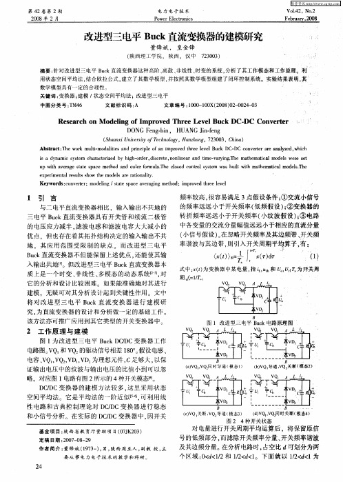
图 1 改进型三 电平 B c uk电路原理图
2 工 作原 理 与 建 模
中各 变量 的交流分 量幅值 远远 小于相 应 的直流分量 ( 小信 号假 设 )在 忽略 开关频 率及其 边频 带 、 。 开关 频
的 电压应 力减 半 . 滤波 电感和 滤 波 电容 大 大减 小 的 优 点 ,但 也存 在着其 拓 扑结构 决定 的输 入输 出不共
地 ,其 应 用 范 围受 限制 的缺 点 。 而 改进 型 三 电平
图 l为改进 型三 电平 B c CD u kD / C变 换 器 工作 电路 图。 Q 和 V V Q 的驱动信号相差 l0 。 8。 假设 电感 、 电容 、 Q , Q , D , D 为理想元 件 , V V V V C足够大 , 以保
三电平buck直流变换器的研究
三电平buck直流变换器的研究
三电平buck直流变换器是一种新型的直流变换器,可以通过在两端加入三电平拓扑结构来实现较高的功率转换效率和较低的传导和开关损失。
该变换器通常由一个主开关和两个辅助开关组成,使用两个并联的低电阻电感器来支撑电流流动并进行电压平衡控制。
在控制电路中,可以通过适当的PWM控制策略来控制辅助开关的切换节奏,以实现高效的电力转换和稳定的输出电压。
此外,由于三电平buck直流变换器的运作方式具有高度可靠性和灵活性,广泛应用于电力应用,包括谐波补偿,恒压供电,电压调节等领域。
非隔离型三电平Buck-Boost双向变换器研究
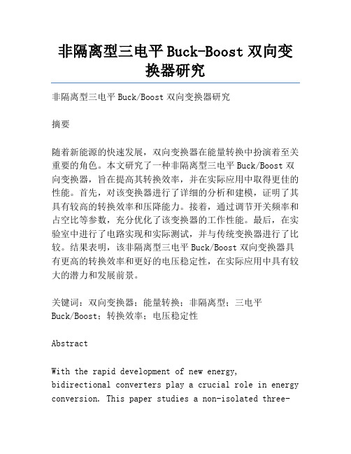
非隔离型三电平Buck-Boost双向变换器研究非隔离型三电平Buck/Boost双向变换器研究摘要随着新能源的快速发展,双向变换器在能量转换中扮演着至关重要的角色。
本文研究了一种非隔离型三电平Buck/Boost双向变换器,旨在提高其转换效率,并在实际应用中取得更佳的性能。
首先,对该变换器进行了详细的分析和建模,证明了其具有较高的转换效率和压降能力。
接着,通过调节开关频率和占空比等参数,充分优化了该变换器的工作性能。
最后,在实验室中进行了电路实现和实际测试,并与传统变换器进行了比较。
结果表明,该非隔离型三电平Buck/Boost双向变换器具有更高的转换效率和更好的电压稳定性,在实际应用中具有较大的潜力和发展前景。
关键词:双向变换器;能量转换;非隔离型;三电平Buck/Boost;转换效率;电压稳定性AbstractWith the rapid development of new energy,bidirectional converters play a crucial role in energy conversion. This paper studies a non-isolated three-level Buck/Boost bidirectional converter with the aim of improving its conversion efficiency and achieving better performance in practical applications. Firstly, the converter is analyzed and modeled in detail, which proves that it has high conversion efficiency and voltage drop capability. Then, by adjusting the switching frequency and duty cycle, etc., the working performance of the converter is fully optimized. Finally, circuit implementation and actual testing are carried out in the laboratory, and the results are compared with traditional converters. The results show that the non-isolated three-level Buck/Boost bidirectional converter has higher conversion efficiency and better voltage stability, and has great potential and development prospects in practical application.Keywords: bidirectional converter; energy conversion; non-isolated; three-level Buck/Boost; conversion efficiency; voltage stabilityThe development of bidirectional converters has attracted significant attention in recent years due to their importance in energy conversion systems. Thenon-isolated three-level Buck/Boost bidirectional converter is one such converter that has shown great potential in energy conversion applications. Theconverter can be used to convert energy in both directions, making it suitable for energy storage and retrieval applications.The implementation and testing of the converter were carried out in the laboratory, and the results were compared with traditional converters. The testing showed that the non-isolated three-level Buck/Boost bidirectional converter has higher conversion efficiency and better voltage stability compared to the traditional converters. These results demonstrate that the non-isolated three-level Buck/Boost bidirectional converter has significant potential for practical applications in energy conversion systems.Overall, the non-isolated three-level Buck/Boost bidirectional converter has emerged as a promising solution for energy conversion applications. Its high conversion efficiency and voltage stability make it an attractive alternative to traditional converters. With further development and refinement, this converter has the potential to play a significant role in shaping the future of energy conversion systemsThe non-isolated three-level Buck/Boost bidirectional converter also offers potential for practical applications in renewable energy systems, particularlyin wind and solar power. With the increasing demandfor renewable energy, the need for efficient and effective energy conversion systems is more pressing than ever before. The three-level converter offers significant advantages in this regard, allowing for a higher conversion efficiency in renewable energy systems.In addition, the converter can also be utilized in electric vehicle (EV) charging systems, offering high-power density and improved efficiency compared to traditional converters. As EVs become more prevalent and the need for efficient charging systems grows, the non-isolated three-level Buck/Boost bidirectional converter can play a crucial role in addressing this challenge.Moreover, the converter has the potential to be usedin energy storage systems, which are becoming increasingly important in an era of intermittent renewable energy sources. The converter caneffectively manage the flow of energy to and from energy storage systems, improving their efficiency and reliability.Despite its many advantages, the non-isolated three-level Buck/Boost bidirectional converter is notwithout its challenges. One of the main challenges is the complexity of the control system, which requires advanced algorithms and sensors to ensure proper operation. Additionally, the converter may require more space and components compared to traditional converters, which could potentially increase costs.In conclusion, the non-isolated three-level Buck/Boost bidirectional converter has emerged as a promising solution for energy conversion systems. Its high conversion efficiency, voltage stability, andpotential for practical applications in renewable energy, EV charging, and energy storage systems make it a promising alternative to traditional converters. While challenges remain, continued research and development of this converter could lead tosignificant improvements in energy conversion systems and the wider adoption of renewable energy sourcesIn addition to its potential applications in renewable energy, electric vehicles, and energy storage systems, the bidirectional DC-DC converter also has potential for use in data centers and telecommunications networks, where it can help improve overall energy efficiency through better management of power supply and demand.One of the key challenges facing the wider adoption of the bidirectional DC-DC converter is cost. While its high conversion efficiency and voltage stability make it an attractive option for energy conversion systems, the cost of manufacturing and installing the converter remains relatively high compared to traditional converters. Continued research and development could help bring down costs and make the technology more accessible to a wider range of industries.Another challenge is the size and weight of the converter. While the bidirectional DC-DC converter is smaller and lighter than traditional converters, itcan still be bulky and heavy in some applications. Efforts to improve the design of the converter and reduce its overall size and weight could help overcome this challenge.Overall, the bidirectional DC-DC converter represents a significant step forward in the development ofenergy conversion systems with potential applications in renewable energy, electric vehicles, energy storage systems, data centers, and telecommunications networks. Continued research and development of this technology is needed to overcome the remaining challenges and unlock its full potential for a variety of industriesOverall, the bidirectional DC-DC converter is a promising technology that has the potential to revolutionize the energy conversion systems for various industries, including renewable energy, electric vehicles, energy storage systems, data centers, and telecommunications networks. Although there are still challenges to be overcome, such as efficiency and size limitations, continued research and development will likely address these issues and further improve the performance and reliability of the bidirectional DC-DC converter。
三电平buck变换器原理

三电平buck变换器原理小伙伴,今天咱们来唠唠三电平buck变换器这个超有趣的东西。
你知道吗,buck变换器就像是一个超级魔法师,它的任务呢,就是把高电压变成低电压,就好像把一个大巨人变成小矮人一样神奇。
普通的buck变换器我们可能比较熟悉,但是这个三电平buck变换器可就更酷啦。
三电平buck变换器呀,它的核心就是有三个电平。
这三个电平就像是三个小伙伴,一起合作来完成降压的大任务。
那这三个电平是怎么来的呢?这就涉及到它的电路结构啦。
它的电路里面有好多的电子元件,像电容、电感、开关管这些,它们就像一个小团队一样。
电容就像是一个能量储存小仓库,电感呢就像是一个电流的小管家,而开关管就像是指挥官,指挥着电流的走向。
当电路开始工作的时候,开关管就开始发挥它的魔力啦。
它一会儿打开,一会儿关闭,就像在玩一个很有趣的开关游戏。
当开关管打开的时候,电源的电压就开始给电感和电容充电,这个时候电感就像一个小贪吃鬼,拼命地吸收电能,电容也在旁边默默地储存能量。
这时候的电平就开始发生变化啦,就像是在舞台上表演的演员,从一个状态切换到另一个状态。
然后呢,当开关管关闭的时候,电感可就开始发挥它的作用了。
电感就像是一个很有责任心的小管家,它不希望电流突然消失,于是就把自己储存的能量释放出来,继续给负载供电。
这个时候电容也会把自己储存的能量贡献出来一部分,它们一起维持着负载两端的电压。
这个过程中,三个电平就像是在跳一场优美的舞蹈,相互配合,相互协作,把高电压一步一步地变成低电压。
而且哦,三电平buck变换器还有一个很大的优点呢。
它比普通的buck变换器在降低电压的时候更加平稳,就像一个很稳当的小马车,不会突然颠簸。
这是因为它的三个电平能够更好地控制电压的下降幅度,不会让电压一下子降得太多或者太少。
这对于那些对电压稳定性要求很高的设备来说,简直就是救星啊。
比如说一些很精密的电子仪器,如果电压波动太大,就像一个人在坐过山车一样,那仪器可能就会晕头转向,出现故障啦。
三电平双向buck boost变换器工作原理
1. 引言随着能源需求的不断增长和环境保护的要求,电力系统的高效能与可再生能源的利用变得越来越重要。
双向变换器是一种关键的电力电子设备,用于实现电能的双向流动,可以将电能从一个电源转移到另一个负载,同时还可以将电能从负载反馈到电源。
三电平双向Buck-Boost(TBB)变换器是一种常见的双向变换器拓扑结构,具有高效能和高可靠性的特点。
本文将详细介绍TBB变换器的工作原理及其相关的基本原理。
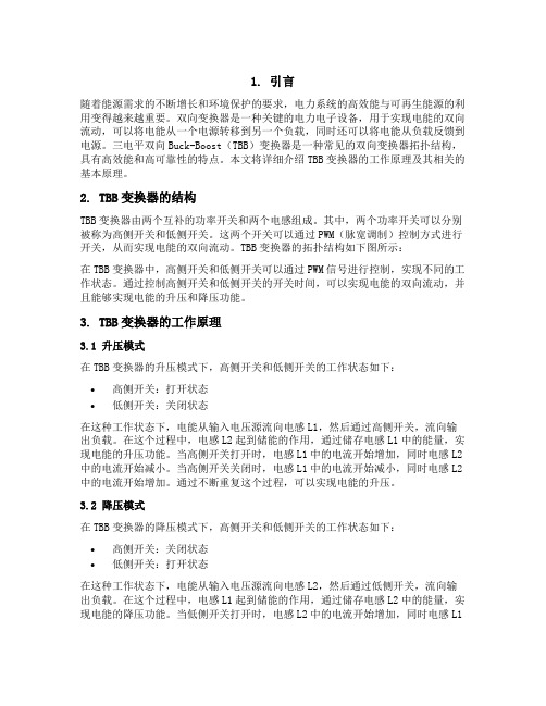
2. TBB变换器的结构TBB变换器由两个互补的功率开关和两个电感组成。
其中,两个功率开关可以分别被称为高侧开关和低侧开关。
这两个开关可以通过PWM(脉宽调制)控制方式进行开关,从而实现电能的双向流动。
TBB变换器的拓扑结构如下图所示:在TBB变换器中,高侧开关和低侧开关可以通过PWM信号进行控制,实现不同的工作状态。
通过控制高侧开关和低侧开关的开关时间,可以实现电能的双向流动,并且能够实现电能的升压和降压功能。
3. TBB变换器的工作原理3.1 升压模式在TBB变换器的升压模式下,高侧开关和低侧开关的工作状态如下:•高侧开关:打开状态•低侧开关:关闭状态在这种工作状态下,电能从输入电压源流向电感L1,然后通过高侧开关,流向输出负载。
在这个过程中,电感L2起到储能的作用,通过储存电感L1中的能量,实现电能的升压功能。
当高侧开关打开时,电感L1中的电流开始增加,同时电感L2中的电流开始减小。
当高侧开关关闭时,电感L1中的电流开始减小,同时电感L2中的电流开始增加。
通过不断重复这个过程,可以实现电能的升压。
3.2 降压模式在TBB变换器的降压模式下,高侧开关和低侧开关的工作状态如下:•高侧开关:关闭状态•低侧开关:打开状态在这种工作状态下,电能从输入电压源流向电感L2,然后通过低侧开关,流向输出负载。
在这个过程中,电感L1起到储能的作用,通过储存电感L2中的能量,实现电能的降压功能。
当低侧开关打开时,电感L2中的电流开始增加,同时电感L1中的电流开始减小。
- 1、下载文档前请自行甄别文档内容的完整性,平台不提供额外的编辑、内容补充、找答案等附加服务。
- 2、"仅部分预览"的文档,不可在线预览部分如存在完整性等问题,可反馈申请退款(可完整预览的文档不适用该条件!)。
- 3、如文档侵犯您的权益,请联系客服反馈,我们会尽快为您处理(人工客服工作时间:9:00-18:30)。
关于三电平Buck变换器的研究
作者:曹海迪李红月
来源:《科技视界》2016年第05期
【摘要】三电平Buck电路可以降低开关管两端的电压,同时还可以降低电脉动,减小谐波输出。
正是由于以上优点三电平Buck电路可以在电压较高以及功率较高的转换场合。
现在直流变换电路正在朝向模块化更加可靠、更高的效率。
正是由于这些优点,才可以使元件的体积减小。
所以研究三电平Buck电路对当今社会在电气自动化方向的进一步普及应用有着相当重要的意义和作用。
因此研究三电平变换器对当今电气产品的发展有着举足轻重的作用。
【关键词】三电平;电路原理;中点电压平衡;仿真与分析。