步进电机相关
步进电机基本参数
步进电机基本参数步进电机(Stepper Motor)是一种将电脑数字信号转变为机械运动的设备,它以离散的方式旋转,每一次脉冲驱动会引起电机一定的运动。
步进电机具有以下几个基本参数。
1. 步数(Step):步进电机的运动是以步为单位的,一步表示电机转动一定的角度或线性距离。
步数也可以用来描述电机的分辨率,即每转多少步,电机转一圈。
通常情况下,步进电机的步数会在说明书或型号参数中给出。
2. 相数(Phase):步进电机的绕组分为几个相,每相两个线圈。
常见的步进电机相数有两相、三相和五相等,不同相数的步进电机在控制方式上有所不同,包括驱动方式和控制电路。
3.驱动方式:步进电机的驱动方式包括全步驱动和半步驱动。
全步驱动是每个脉冲都使电机转动一个步进角度,半步驱动是在全步的基础上细分每一步,在一个脉冲内实现小角度的运动。
半步驱动可以提高电机的分辨率和运动平滑度。
4. 转矩(Torque):步进电机的转矩是指电机产生的旋转力矩。
转矩大小与电机的结构、驱动方式和电流有关,通常在电机的规格表中有相关的数据。
5. 电流(Current):步进电机电流是指电机所需工作电流。
电机的电流大小与驱动方式、负载情况有关。
一般情况下,为了保证电机正常运行,需要匹配合适的电流驱动器。
6. 驱动电压(Voltage):步进电机的驱动电压是指驱动电机所需的电压。
电机的驱动电压应该与驱动器供电电压相匹配。
7. 最大速度(Maximum Speed):步进电机的最大速度是指电机能够达到的最高旋转速度。
最大速度与电机的结构、驱动方式、驱动电压和电流有关。
除了上述基本参数,还有一些其他的参数也需要考虑,比如电机的精度、响应时间、机械惯性等。
这些参数在具体应用中会根据实际需求进行选择和调整。
总的来说,步进电机的基本参数包括步数、相数、驱动方式、转矩、电流、驱动电压和最大速度等。
这些参数决定了电机的性能和适用范围,需要根据具体应用需求进行选择和配置。
步进电机及驱动器原理知识【知识讲解】课件

步进电机在医疗设备领域的应用逐渐增多,如手 术机器人、诊断设备和康复设备等。
智能家居
步进电机在智能家居领域的应用也日益广泛,如 智能门锁、智能窗帘和智能照明等。
无人机和机器人
步进电机在无人机和机器人领域的应用也取得了 重要进展,如飞行控制系统和机械臂等。
对未来发展的展望
1 2 3
创新驱动 未来步进电机的技术发展将更加依赖于创新驱动, 包括新材料、新工艺和新技术的应用。
在机器人领域的应用
关节驱动
步进电机常用于机器人的 关节驱动,实现机器人的 各种复杂动作和姿态。
移动机构
步进电机可以驱动机器人 的移动机构,实现机器人 在各种地形和环境中的稳 定行走。
操控手部
步进电机可以用于机器人 的手部操作,实现抓取、 搬运和操作等动作的精确 控制。
在其他领域的应用
医疗器械
航空航天
查并紧固相关部件。
过热或冒烟
可能是由于电机过载、电源电 压过高或驱动器故障,需要检 查电机负载、电源电压和驱动 器状态。
噪声或异响
可能是由于轴承磨损、齿轮损 坏或其他机械故障,需要检查 并更换相关部件。
不通电或无响应
可能是由于电源故障、接线不 良或驱动器故障,需要检查电
源、接线和驱动器状态。
05
步进电机发展趋势
驱动器的选择
根据电机类型选择
不同类型的步进电机需要选择相 应的驱动器,例如直流步进电机 需要选择直流步进电机驱动器, 交流步进电机需要选择交流步进
电机驱动器。
根据控制系统选择
不同的控制系统需要选择相应的 驱动器,例如PLC控制系统需要 选择与PLC控制系统兼容的驱动
器。
根据性能要求选择
步进电机复习题

步进电机复习题步进电机复习题步进电机是一种常见的电动机类型,具有精准的位置控制和高效的运行特性。
在工业自动化、机器人技术和医疗设备等领域得到广泛应用。
为了更好地理解和掌握步进电机的原理和应用,下面将给出一些复习题,帮助读者巩固相关知识。
一、选择题1. 步进电机的转子是由哪些部分组成的?A. 磁极B. 导线圈C. 磁铁D. 电刷2. 步进电机的驱动方式主要有哪几种?A. 单相驱动B. 双相驱动C. 三相驱动D. 四相驱动3. 步进电机的转子位置是通过什么信号控制的?A. 电流信号B. 电压信号C. 脉冲信号D. 频率信号4. 步进电机的步距角是指什么?A. 转子每转动一周所需的脉冲数B. 转子每转动一步所需的脉冲数C. 转子每转动一度所需的脉冲数D. 转子每转动一弧度所需的脉冲数5. 步进电机的控制方式主要有哪几种?A. 开环控制B. 闭环控制C. 反馈控制D. 前馈控制二、判断题1. 步进电机可以实现连续旋转。
A. 对B. 错2. 步进电机的转速与输入脉冲频率成正比。
A. 对B. 错3. 步进电机的定位精度比直流电机高。
A. 对B. 错4. 步进电机的转矩与输入电流成正比。
A. 对B. 错5. 步进电机可以通过改变电压来控制转速。
A. 对B. 错三、简答题1. 什么是步进电机的步进角?步进角是指步进电机每接收一个脉冲信号后所转动的角度。
它与电机的结构和控制方式有关,可以通过改变驱动信号的频率和脉冲数来控制步进电机的转动角度和速度。
2. 步进电机的驱动方式有哪些优缺点?单相驱动适用于简单的应用场景,但转矩较小;双相驱动具有较高的转矩和较好的控制性能,但相对复杂;三相驱动具有更高的转矩和更好的运行平稳性,但需要更多的驱动电路;四相驱动是常用的驱动方式,具有较高的转矩和较好的控制性能。
3. 步进电机的控制方式有哪些应用场景?开环控制适用于对转动精度要求不高的场景,如打印机、扫描仪等;闭环控制适用于对转动精度要求较高的场景,如数控机床、机器人等;反馈控制适用于需要实时监测转子位置的场景,如医疗设备、精密仪器等;前馈控制适用于需要提前预测转子位置的场景,如高速运动控制系统等。
步进电机的原理
步进电机的原理
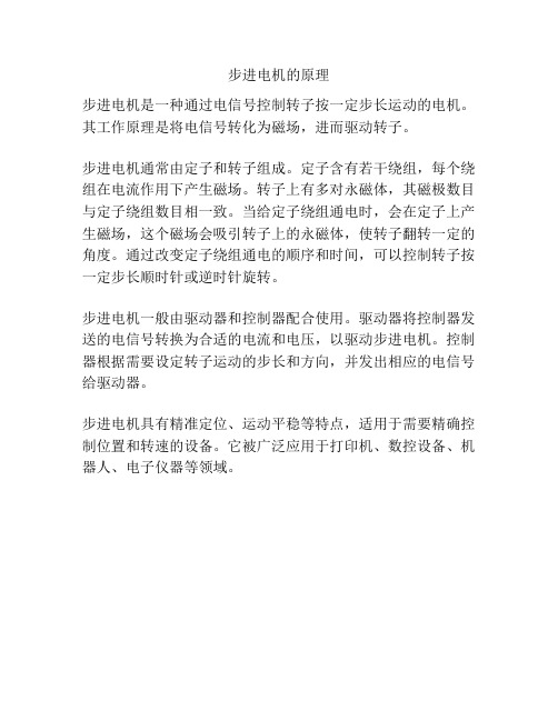
步进电机是一种通过电信号控制转子按一定步长运动的电机。
其工作原理是将电信号转化为磁场,进而驱动转子。
步进电机通常由定子和转子组成。
定子含有若干绕组,每个绕组在电流作用下产生磁场。
转子上有多对永磁体,其磁极数目与定子绕组数目相一致。
当给定子绕组通电时,会在定子上产生磁场,这个磁场会吸引转子上的永磁体,使转子翻转一定的角度。
通过改变定子绕组通电的顺序和时间,可以控制转子按一定步长顺时针或逆时针旋转。
步进电机一般由驱动器和控制器配合使用。
驱动器将控制器发送的电信号转换为合适的电流和电压,以驱动步进电机。
控制器根据需要设定转子运动的步长和方向,并发出相应的电信号给驱动器。
步进电机具有精准定位、运动平稳等特点,适用于需要精确控制位置和转速的设备。
它被广泛应用于打印机、数控设备、机器人、电子仪器等领域。
步进电机介绍及相关参数与操作说明书

IntroductionASASC5-Phase Microstep RK 2-Phase Full/Half UMK 5-PhaseMicrostep CRK 2-Phase Microstep RBK 2-Phase Microstep CMK 2-Phase PK/PV 2-Phase PK EMP400SG8030J AccessoriesInstallationAC InputDC InputAC InputDC Input Without Encoder With EncoderControllersConnection and Operation■Names and Functions of Driver Parts●(Top)□2 Function Switches □1 Signal Monitor Displays◇Alarm◇(Front)□3 Motor Run Current Switch □4 Step Angle Setting Switch □1 Signal Monitor Displays □5 Input/Output Signals Motor TerminalsPower Input TerminalsProtective Earth TerminalsThe step angle set with the step angle setting switch will become effective when the "Step●Angle Select" (CS) signal input is OFF.Do not change the "Step Angle Select" (CS) signal input or step angle setting switch while ●the motor is operating. It may cause the motor to misstep and stop. Change the step angle setting switch, when the "Step Angle Select" (CS) signal input is OFF and the "Excitation Timing" (TIM) signal output is ON.The cable for connecting the terminal box type motor and driver, and the D-Sub (15-pin) connector for connecting to the driver's CN1 connector are not included. They must be supplied separately. ✽Description of input/output signals ➜ Page C-177Connection Diagrams●5 VDC Connection or Line Driver Input◇DriverController24 VDC Connection◇DriverInput Signal Connection◇Pulse (PLS) Signal, Rotation Direction (DIR) Signal●You can select either 5 VDC or 24 VDC as the signal voltage. Line driver input is also available. The pin No. to connect differs according to the signal voltage.All Windings Off Signal, Step Angle Select Signal●You can select either 5 VDC or 24 VDC as the signal voltage. The pin No. to connect is the same for 5 VDC and 24 VDC.Output Signal Connection◇Keep the output signal voltage and current below 30 VDC and 10 mA respectively.Power Supply◇Use a power supply that can supply sufficient input current. When power supply capacity is insufficient, a decrease in motor output can cause the following malfunctions: Motor does not operate properly at high-speed. ●Slow motor startup and stopping.●Notes on Wiring◇Use twisted-pair wires of AWG26 and keep wiring as short as possible [within 2 m (6.6 ft.)]. ●Note that as the length of the pulse signal line increases, the maximum transmission ●frequency decreases. Technical reference ➜ Page F-54Use wires of AWG18 or thicker for motor lines (when extended), power supply lines and ●protective earth line.To ground the driver, lead the ground conductor from the protective earth terminal (M4) and ●connect the ground conductor to provide a common ground point.Signal lines should be kept at least 2 cm (0.79 in.) away from power lines (power supply lines ●and motor lines). Do not bind the signal lines and power lines together.If noise generated by the motor cable or power cable becomes a problem due to the wiring ●and layout, shield the cables or use ferrite cores.Incorrect connection of DC power input will lead to driver damage. Make sure that the polarity ●is correct before turning power on.The cable for connecting the terminal box type motor and driver, and the D-Sub (15-pin) ●connector for connecting to the driver's CN1 connector are not included. They must be supplied separately.●Driver Motor Terminals and Motor Leads/Motor Terminal BlocksTerminal Box Type Motor Connections ◇RBK264T , RBK266T ,RBK268T∼16)[Diameter: (ϕ0.28∼ϕ0.51 in.)]✽ (M4)InternalTerminal ✽ (M4)(AWG18 or thicker)(AWG18 or thicker)Connect motor lead wires to the terminals 2 to 5.12345Terminal BlockConnect either the internal protective earth terminal or external protective earth terminal to the ground.✽RBK296T , RBK299T , RBK2913T✽ (M4)∼16)InternalTerminal ✽ (M4)[Diameter: ϕ7(ϕ0.28∼ϕ0.51 in.)](AWG18 or thicker)54123678Connect either the internal protective earth terminal or external protective earth terminal to the ground.✽Terminals 1, 4, 5, and 8 are used. Terminals 2, 3, 6, and 7 are not used. Do not connect anything to them.IntroductionASASC5-Phase Microstep RK 2-Phase Full/Half UMK 5-Phase Microstep CRK2-Phase Microstep RBK 2-Phase Microstep CMK 2-Phase PK/PV 2-Phase PK EMP400SG8030J Accessories InstallationAC InputDC InputAC InputDC InputWithout Encoder With EncoderControllersPulse (PLS), Rotation Direction (DIR) Input SignalYou can select either 5 VDC or 24 VDC as the signal voltage for"Pulse" input and "Rotation Direction" input. Line driver input is also available.Input Circuit and Sample Connection ◇5 VDC Connection●24 VDC Connection●Line Driver Input●Pulse Waveform Characteristics ◇5 VDC or 24 VDC Connection●ONON Pulse Input SignalRotation Direction Input Signal 1 Pulse duty: 50% and belowLine Driver Input●ONON Pulse Input SignalRotation Direction Input Signal 1 Pulse duty: 50% and below1 ✽ The shaded area indicates when the photocoupler diode is ON. The motor moves when thephotocoupler state changes from ON to OFF.2 ✽ The minimum interval time when changing rotation direction is 10 μs. This value variesgreatly depending on the motor type, pulse frequency and load inertia.Pulse Signal Characteristics◇Keep the pulse signal at the "photocoupler OFF" state when no ●pulses are being input.Leave the pulse signal at rest ("photocoupler OFF") when ●changing rotation directions.All Windings Off (AWO), Step Angle Select (CS) Input Signal Input Circuit and Sample Connection◇All Windings Off (AWO) Input Signal◇Inputting this signal puts the motor in a non-excitation (free) state. ●This signal is used when turning the motor by external force or ●manual home position is desired. The photocoupler must be "OFF" when operating the motor.ON OFFAll Windings Off Input Signal Motor CurrentMotor Holding TorqueThe shaded area indicates that the motor provides holding torque in proportion to standstill current set by motor stop current switch.Switching the "All Windings Off" signal from "photocoupler ON" to ●"photocoupler OFF" does not alter the excitation sequence. When the motor shaft is manually adjusted with the "All Windings Off" signal input, the shaft will shift up to ±3.6° from the position set after the "All Windings Off" signal is released.Step Angle Select (CS) Input Signal◇When this signal input is "ON," the motor will operate at the basic ●step angle regardless of the settings of the step angle settingswitches. When the signal input is "OFF ," the motor will operate at the step angle set with the step angle setting switch.To change the step angle, do so when the "Excitation Timing" ●signal output is "ON" and the motor is at standstill.Current Cutback (CD), Alarm (ALM), Excitation Timing (TIM) Output SignalOutput Circuit and Sample Connection◇Current Cutback (CD) Output Signal◇When the automatic current cutback function is activated, the ●"Current Cutback" output turns on.Alarm (ALM) Output Signal◇When the motor is running, if the driver overheat, overvoltage, or ●overcurrent protective function is detected, the "Alarm" output turns off, and the ALARM LED of the driver flashes. The current to the motor is also cut off to stop the motor.You can count the number of times the ALARM LED flashes to ●confirm which protective function is activated.This signal normally stays on, but turns off when a protective ●function is activated.Excitation Timing (TIM) Output Signal◇The "Excitation Timing" signal is output to indicate when the motor ●excitation is in the initial stage (step "0" at power up).The "Excitation Timing" signal is output simultaneously with a ●pulse input each time the excitation sequence returns to step "0." The excitation sequence will complete one cycle for every 7.2˚ rotation of the motor output shaft.Microsteps/step 1: S ignal is output once every 4 pulses.Microsteps/step 4: S ignal is output once every 16 pulses.Timing chart at 1.8/step (Microsteps/step 1)When connected as shown in the sample connection, the signal will be ✽"photocoupler ON " at step "0."Pulse Input Rotation Direction Input Excitation Timing Output ✽12345678910(Step)01230123012321011121314Notes:When power is turned ON, the excitation sequence is reset to step "0" and the "Excitation ●Timing" signal is output.When operating the motor using the ●"Excitation Timing " signal output, make sure the motor output shaft stops at an integral multiple of 7.2˚.Timing Chart●Rotation Direction Input Signal Pulse Input Signal All Windings Off Input Signal Step Angle Select Input Signal Current Cutback Output Signal MotorPower Input The section indicates that the photocoupler diode is emitting light.1 ✽ The minimum switching time to change direction 10 μs isshown as the response time of the circuit. The motor may need more time than that.2 ✽ Depends on load inertia, load torque, and starting frequency.3 ✽ Never input a pulse signal immediately after switching the"All Windings Off " signal to the "photocoupler OFF" state. The motor may not start.4 ✽ To cycle the power, turn off the power and then wait for atleast five seconds after the POWER LED has turned off.。
步进电机威力计算公式
步进电机威力计算公式步进电机是一种特殊的电机,它可以将电脉冲信号转换为机械运动。
步进电机的威力是指其输出的力量大小,通常用于评估电机的性能和适用范围。
在实际应用中,我们经常需要计算步进电机的威力,以便选择合适的电机来满足特定的需求。
本文将介绍步进电机威力的计算公式及其相关知识。
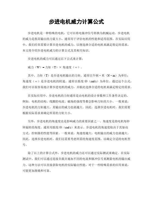
步进电机的威力可以通过以下公式来计算:威力(W)= 力矩(T)×角速度(ω)。
其中,力矩(T)是步进电机输出的力矩,通常以牛顿·米(N·m)为单位;角速度(ω)是步进电机的转速,通常以弧度/秒(rad/s)为单位。
通过这个公式,我们可以很容易地计算步进电机的威力,并据此选择合适的电机来满足特定的需求。
在实际应用中,步进电机的力矩通常是由电机的设计参数和工作条件决定的。
例如,电机的结构、线圈的电流、磁场的强度等都会影响力矩的大小。
一般来说,步进电机的力矩越大,其输出的威力也就越大。
因此,选择步进电机时,我们需要根据实际需求来确定所需的力矩大小。
另外,步进电机的角速度也是影响威力的重要因素之一。
角速度是指电机每秒钟旋转的角度,通常用弧度/秒(rad/s)来表示。
步进电机的角速度取决于其驱动方式、控制器的性能等因素。
一般来说,角速度越大,电机输出的威力也就越大。
因此,选择步进电机时,我们还需要考虑所需的角速度范围,以确定合适的电机型号。
除了以上的计算公式外,步进电机的威力还可以通过实际测试来确定。
在实际测试中,我们可以通过连接负载并施加不同的电流和脉冲信号来测量电机的输出威力。
这种方法可以直接获取电机的实际输出性能,对于一些特殊需求的应用来说,可能更加准确和可靠。
在选择步进电机时,我们还需要考虑一些其他因素,如电机的尺寸、重量、功率等。
这些因素都会影响电机的适用范围和性能表现。
因此,在实际应用中,我们需要综合考虑以上因素,选择合适的步进电机来满足特定的需求。
总之,步进电机的威力是评估其性能和适用范围的重要指标之一。
步进电机工作原理

步进电机工作原理
步进电机是一种控制精度较高的电机,它的工作原理是通过对电机的电流进行精确控制来实现旋转。
步进电机通常由一个固定的磁体和一个旋转的转子组成。
固定磁体中有若干个磁极,而转子上也有相应的磁极。
这些磁极的排列方式决定了电机的工作方式。
步进电机的转动是通过改变电流的方向和大小来实现的。
当电流通过固定磁体时,会产生一个磁场,这个磁场会与转子上的磁场相互作用,从而使得转子旋转到一个新的位置。
当电流的方向和大小改变时,转子也会相应地改变位置。
为了精确定位,步进电机通常会将转子分为几个等距的位置,每个位置都与一个特定的电流模式相对应。
通过改变电流的方式,可以使转子逐步移动到下一个位置,从而实现精确的旋转。
步进电机的转子移动是离散的,而不是连续的。
这意味着它可以精确定位,并且不需要使用传统的位置反馈设备来监测转子的位置。
步进电机适用于需要精确控制和定位的应用,如打印机、数控机床和机器人等。
总之,步进电机通过精确控制电流来实现转子的旋转,从而实现精确的位置控制。
它的工作原理基于磁场的相互作用,使得转子可以按照离散的步进来旋转。
步进电机调研报告

步进电机调研报告《步进电机调研报告》一、引言步进电机作为一种常见的电机类型,在各种电气设备中得到广泛应用。
其精准的位置控制、简单的驱动方式和可靠的性能使其在工业自动化、医疗设备、汽车电子等领域发挥着重要作用。
本报告旨在对步进电机进行调研,了解其发展现状和未来趋势,为相关领域的研究和应用提供参考。
二、步进电机的基本原理和特点步进电机是利用电脉冲驱动的电机,其工作原理是通过控制电流变化使定子旋转(步进运动),因此可以实现精确的位置控制。
步进电机具有结构简单、控制方便、低成本、高精度等特点,因此在许多领域有着广泛的应用。
三、步进电机的应用领域1. 工业自动化领域:步进电机广泛应用于各种数控机床、包装机械、激光切割设备等自动化设备中。
2. 医疗设备领域:医疗影像设备、手术机器人等医疗设备中需要精确位置控制的场合,步进电机也有应用。
3. 汽车电子领域:汽车座椅调节、车窗升降系统、天窗开闭系统等都可能采用步进电机。
四、步进电机的发展现状当前,随着工业自动化的快速发展,步进电机在工业机器人、3D打印、智能制造等领域得到了广泛的应用。
同时,步进电机的性能也得到了不断的提升,如响应速度、扭矩密度、功率密度等方面都得到了改进。
五、步进电机的未来趋势未来,随着人工智能、物联网、大数据等技术的发展,步进电机将会在更多领域得到应用。
同时,对于步进电机的驱动技术、节能降耗、智能化控制等方面也将得到更多的研究和发展。
六、结论步进电机作为一种重要的电机类型,在工业自动化、医疗设备、汽车电子等领域都有着广泛的应用前景。
未来,随着技术的不断发展,步进电机的性能和应用领域将会得到更多的拓展和发展。
- 1、下载文档前请自行甄别文档内容的完整性,平台不提供额外的编辑、内容补充、找答案等附加服务。
- 2、"仅部分预览"的文档,不可在线预览部分如存在完整性等问题,可反馈申请退款(可完整预览的文档不适用该条件!)。
- 3、如文档侵犯您的权益,请联系客服反馈,我们会尽快为您处理(人工客服工作时间:9:00-18:30)。
ULN2003
单片机IO口的输出电流很小,一般高电平拉电流在0.08-0.16mA,低电平灌电流最大为20mA以内(低有效),无法直接驱动大电流被控元器件,需要由功率电路来扩展输出电流以满足被控元件的电流,电压。
ULN2XXXX为高压大电流达林顿晶体管陈列,由七个NPN达林顿管组成,属于可控大功率器件。
原理:LN2003是一个7路反向器电路,即当输入端为高电平时输出端为低电平,当输入端为低电平时输出端为高电平,继电器得电吸合。
功能特点:
ULN2003 的每一对达林顿都串联一个2.7K 的基极电阻,在5V 的工作电压下它能与TTL 和CMOS电路直接相连,可以直接处理原先需要标准逻辑缓冲器来处理的数据。
ULN2003工作电压高,工作电流大,灌电流可达500mA,并且能够在关态时承受50V 的电压,输出还可以在高负载电流并行运行。
高电压输出50V
输出钳位二极管
输入兼容各种类型的逻辑电路
应用继电器驱动器
ULN2003A ULN2004A ULQ2003A ULQ2004A内部电路图
比例电路主要对输入信号进行比例放大。
由于电路中不存在储能元件,因此其无频率变化特性。
基本的微积分电路是由R与C串联组成,当输出量取自R时为微分,输出量取自C时为积分;主要利用电容C的充放电在时域范围内实现对信号的微分和积分运算。
微分电路中矩形脉宽T应远大于时间常数τ,将方波变换为尖脉冲,积分电路矩形脉宽T应远小于时间常数τ,将方波变换为三角(锯齿)波。
此外,还广泛应用于A/D转换器等芯片集成技术中。
PID 自动/手动调节的无扰动切换
有些工程项目中可能需要根据工艺要求在不同的时刻投入、或者退出 PID 自动控制;退出 PID 自动控制时,控制器的输出部分可以由操作人员直接手动控制。
这就是所谓的 PID 手动/自动切换。
PID 控制处于自动方式时,PID 控制器(S7-200 中的 PID 调节功能)会按照 PID 算法,自动通过输出的作用使过程反馈值跟随给定值变化,并保持稳定。
这是一个自动的闭环控制系统。
操作人员可以根据现场工艺的要求,改变给定(即设定值)的值。
PID 控制处于手动方式时,PID 控制器不再起自动计算的作用。
这时,控制回路的输出是由操作人员手动控制、调整,由操作人员观察现场的控制效果,从而构成人工闭环控制。
所谓 PID 自动/手动控制,就是看控制系统的输出是由 PID 控制器自动控制,还是由操作人员手动控制。
有些控制系统的执行机构不能承受较大的冲击,这就要求在进行 PID 自动/手动切换时,保持控制输出的稳定。
这就是要求无扰动切换。
为了达到 PID 自动/手动控制的无扰动切换,需要在编程时注意一些相关事项。
下面分别就直接使用 PID 指令编程,和使用 PID 向导编程两种情况作一介绍。