1SE402-3;中文规格书,Datasheet资料
2SK1740-4-TB-E中文资料(sanyo)中文数据手册「EasyDatasheet - 矽搜」
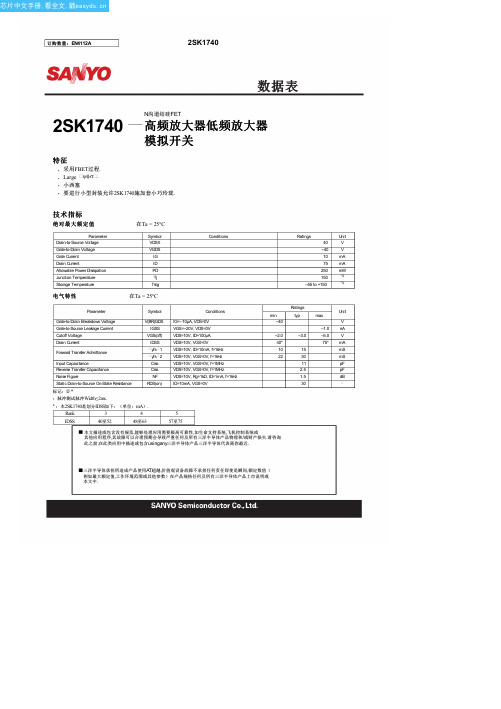
漏极电流ID - 毫安
--2.0V
漏 - 源电压VDS - 毫伏
--2.5V
ID -- VDS
VGS=0V
--0.5V
漏极电流ID - 毫安
--1.0V
--3.0V
--1.5V
--2.0V --2.5V
漏 - 源电压VDS - V
ID -- VGS
VDS=10V
5mA=7 SS ID5来自m4A0mA5 57至75
Ratings
Unit
min
typ
max
--40
V
--1.0 nA
--2.0
--3.0
--5.0 V
40*
75* mA
10
15
mS
22
30
mS
11
pF
2.5
pF
1.5
dB
30
本文描述或包含没有规范,能够处理应用需要极高可靠性,如生命支持系统,飞机控制系统或 其他应用程序,其故障可以合理预期会导致严重任何及所有三洋半导体产品物理和/或财产损失.请咨询 此之前,在此类应用中描述或包含usingany三洋半导体产品三洋半导体代表离你最近.
f=100MHz
通用门
--gfg
16
BFG,G12FG - 质谱
8
4
bfg
0
0
4
8
12
16
漏栅极电压,副总监 - V
ITR01970
--1.0 3
5
fs - 质3谱 y
2
4
5
7
漏电流,IDSS - 毫安
yfs -- IDSS
yfs 2(VGS=0V)
402 1 电动门用户手册说明书
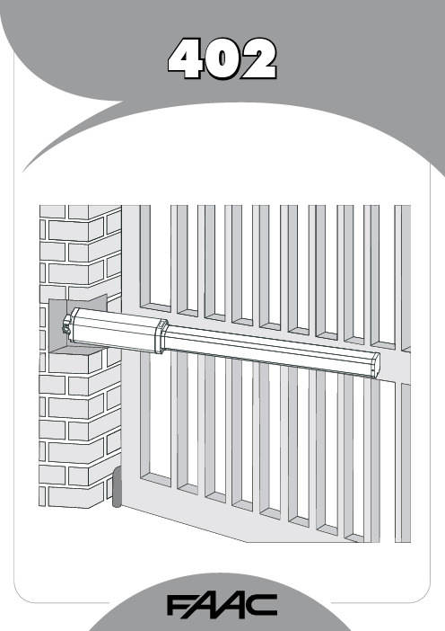
1FAAC S.p.A.Via Benini, 140069 Zola Predosa (BO) - ITALIATel.: 051/61724 - Fax: 051/758518www.faac.it732143 Rev.A.EC DECLARATION OF CONFORMITY FOR MACHINES ....................................................................................p. 2 WARNINGS FOR THE INSTALLER .......................................................................................................................p. 2 1.DESCRIPTION AND TECHNICAL SPECIFICATIONS ....................................................................................p. 31.1.DIMENSIONS ................................................................................................................................p. 32.ELECTRIC DEVICES (standard system) ....................................................................................................p. 33.INSTALLING THE AUTOMATED SYSTEM ......................................................................................................p. 43.1.PRELIMINARY CHECKS ................................................................................................................p. 43.2.INSTALLATION DIMENSIONS ........................................................................................................p. 43.2.1.GENERAL RULES FOR DETERMINING THE INSTALLATION DIMENSIONS ............................p. 43.3.INSTALLATION OF THE OPERATORS .............................................................................................p. 44.START-UP ....................................................................................................................................................p. 64.1.ADJUSTING THE ANTI-CRUSHING SYSTEM ..................................................................................p. 65.FINAL OPERATIONS ...................................................................................................................................p. 76.AUTOMATED SYSTEM TEST .........................................................................................................................p. 77.MANUAL OPERATION ...............................................................................................................................p. 78.RESTORING NORMAL OPERATION MODE ................................................................................................p. 79.MAINTENANCE ..........................................................................................................................................p. 710.REPAIRS .....................................................................................................................................................p. 711.TROUBLE SHOOTING .................................................................................................................................p. 821)ATTENTION! To ensure the safety of people, it is important that you readall the following instructions. Incorrect installation or incorrect use of the product could cause serious harm to people.2)Carefully read the instructions before beginning to install the product.3)Do not leave packing materials (plastic, polystyrene, etc.) within reachof children as such materials are potential sources of danger.4)Store these instructions for future reference.5)This product was designed and built strictly for the use indicated in thisdocumentation. Any other use, not expressly indicated here, could compromise the good condition/operation of the product and/or be a source of danger.6)FAAC declines all liability caused by improper use or use other than thatfor which the automated system was intended.7)Do not install the equipment in an explosive atmosphere: the presenceof inflammable gas or fumes is a serious danger to safety.8)The mechanical parts must conform to the provisions of Standards EN12604 and EN 12605.For non-EU countries, to obtain an adequate level of safety, the Standards mentioned above must be observed, in addition to national legal regulations.9)FAAC is not responsible for failure to observe Good Technique in theconstruction of the closing elements to be motorised, or for any deformation that may occur during use.10)The installation must conform to Standards EN 12453 and EN 12445.For non-EU countries, to obtain an adequate level of safety, the Standards mentioned above must be observed, in addition to national legal regulations.11)Before attempting any job on the system, cut out electrical power .12)The mains power supply of the automated system must be fitted with anall-pole switch with contact opening distance of 3mm or greater. Use of a 6A thermal breaker with all-pole circuit break is recommended.13)Make sure that a differential switch with threshold of 0.03 A is fittedupstream of the system.14)Make sure that the earthing system is perfectly constructed, andconnect metal parts of the means of the closure to it.15)The safety devices (EN 12978 standard) protect any danger areasagainst mechanical movement Risks , such as crushing, dragging,and shearing.16)Use of at least one indicator-light (e.g. FAACLIGHT ) is recommendedfor every system, as well as a warning sign adequately secured to the frame structure, in addition to the devices mentioned at point “15”.17)FAAC declines all liability as concerns safety and efficient operationof the automated system, if system components not produced by FAAC are used.18)For maintenance, strictly use original parts by FAAC.19)Do not in any way modify the components of the automated system.20)The installer shall supply all information concerning manual operationof the system in case of an emergency, and shall hand over to the user the warnings handbook supplied with the product.21)Do not allow children or adults to stay near the product while it isoperating.22)Keep remote controls or other pulse generators away from children,to prevent the automated system from being activated involuntarily.23)Transit through the leaves is allowed only when the gate is fully open.24)The user must not attempt any kind of repair or direct action whateverand contact qualified personnel only.25)Maintenance: check at least every 6 months the efficiency of thesystem, particularly the efficiency of the safety devices (including,where foreseen, the operator thrust force) and of the release devices.26)Anything not expressly specified in these instructions is not permitted.WARNINGS FOR THE INSTALLERGENERAL SAFETY OBLIGATIONSEC DECLARATION OF CONFORMITY FOR MACHINES(DIRECTIVE 98/37/EC)Manufacturer:FAAC S.p.A.Address:Via Benini, 1 - 40069 Zola Predosa BOLOGNA - ITALY Declares that:402 mod. operator,•is built to be integrated into a machine or to be assembled with other machinery to create a machine under the provisions of Directive 98/37/EC;•conforms to the essential safety requirements of the following EEC directives:73/23/EEC and subsequent amendment 93/68/EEC.89/336/EEC and subsequent amendment 92/31/EEC and 93/68/EECand also declares that it is prohibited to put into service the machinery until the machine in which it will be integrated or of which it will become a component has been identified and declared as conforming to the conditions of Directive 98/37/EC.Bologna, 01 January 2005The Managing DirectorA. Bassi3These instructions apply to the following models:402 CBC - 402 SBSThe FAAC 402 automated system for swing leaf gates consists of an enbloc composed of an electric pump and a hydraulic piston which transmits drive to the leaf.The model with a hydraulic locking does not require installation of electric locks, as it guarantees mechanical locking of the leaf when the motor is not operating.The model without a hydraulic locking, requires the installation of electric locks to ensure the leaf is mechanically locked.The 402 automated systems were designed and built to automate swing leaf gates. Do not use for any other purpose.Tab. 1: Technical specifications of “402 Operator”MODEL402 CBC402 SBSPower supply voltage 230 Vac(+6%-10%) 50 (6o) Hz Rod extension speed 1.3 cm/s 1 cm/s Pump flow rate1 l/min 0.75 l/min Traction and thrust force 0-500 daN0-690 daNOperating ambient temperature -40°C - +55°CAbsorbed power 220 W Absorbed current 1 A Motor rotation speed 1400 rpm Motor winding temperature 120°C Weight 6.5 kg Type of oil FAAC HP OILProtection class IP 55Single leaf max length 1,80 m3,00 mUse frequency55 (cycles/hour)4To ensure a correctly operating automated system, the structure of the existing gate or gate to be built must satisfy the following requirements:•Max length of leaves according to the dimensions of Table 1 on page 3.• A strong and rigid leaf structure.•Smooth, uniform leaves movement, without any irregular friction during the entire travel;•Existing hinges in good condition.•Travel limit mechanical stops must be provided.We advise you to carry out the metalwork jobs before installing the automated system.The condition of the structure directly influences the reliability and safety of the automated system.Table A : Recommended dimensions for standard operatorsc = The effective rod stroke is shorter than the maximum stroke, inorder to prevent the rod from reaching its stop point internally, during the opening and closing stages.(*) Rod effective stroke (**) maximum dimension1)Fasten the rear attachment on the pilaster, following the indications in Table A . Modify, if necessary, the length of the supplied attachment.Attention : To avoid compromising good operator functionality, we recommend you to respect the indicated dimensions.• For iron pilasters, accurately weld the rear attachment (ref.ባ, Fig. 6) directly on the pilaster.• For masonry pilasters, select one of the following solutions:A)appropriately lay a walling-in plate and then accurately weld the rear attachment.B)secure, with screws and expansion plugs, the rear attachment plate (ref. a, Fig.6) to the pilaster and then accurately weld the rear attachment to theplate as shown in Fig. 6.If the dimensions indicated in table A or B cannot be executed,the following must be considered in order to determine different measurements:-to obtain 90° opening of the leaf: a + b = c.-to obtain over 90° opening of the leaf: a + b < c.-lower a and b dimensions will result in higher speeds . We advise you to observe the current legal regulations;-limit the difference of the a and b dimensions to within 40 mm :higher differences will considerably vary speed during the opening and closing motion;-for reasons of operator dimensions, the minimum Z dimension is 50 mm (Fig. 4);-if the pilaster dimensions or the position of the hinge (dimension d ) do not make it possible to contain dimension a to the required size, a niche must be made in the pilaster as shown in Opening angle 90°110°a (mm)120100b (mm)120100c(*)(mm)240240d(**)(mm)705056-Lastly, remove the key and restore the power supply to the system.For any repairs, contact FAAC’s authorised Repair Centres.78The following table will help you identify and solve some particular conditions.CONDITIONGate not moving.Gate moving slowly.Gate moving jogwise.The operator is losing oil from the breather screw.The leaves stop at slow-down.Gate speed not constant.A B CD E FSUGGESTION-Check if mains power is supplied.-Make sure that the operator is not unlocked. (chapter 8.).-Check the adjustment of the anti-crushing system (paragraph 4.1).-Check oil level inside the tank. (chapter 9 - Fig. 16).-Check the connection and operation of the thrust capacitor.-Check the efficiency of the electronic control unit.-Check the adjustment of the anti-crushing system (paragraph 4.1).-Make sure that you have removed the breather screw (chapter 5).-Run some complete gate opening and closing cycles, in order to release any air inside the piston.-An initial, minimum oil leak is normal. A larger leak may occur if the operator is not fitted in a perfectly horizontal plane. If the oil leak does not stop soon, weadvise you to visit an authorised repair centre.-Check the adjustment of the anti-crushing system (paragraph 4.1).-Incorrect installation dimensions (paragraph 3.2).Notes919M A I N T E N A N C E R E G I S T E R.o N e t a D b o j f o n o i t p i r c s e D se r u t a n g i S 1_______________________________________________________________________________________________________________________________________na i c i n h c e T re m o t s u C 2_______________________________________________________________________________________________________________________________________na i c i n h c e T re m o t s u C 3_______________________________________________________________________________________________________________________________________na i c i n h c e T re m o t s u C 4_______________________________________________________________________________________________________________________________________na i c i n h c e T re m o t s u C 5_______________________________________________________________________________________________________________________________________na i c i n h c e T re m o t s u C 6_______________________________________________________________________________________________________________________________________na i c i n h c e T re m o t s u C 7_______________________________________________________________________________________________________________________________________na i c i n h c e T re m o t s u C 8_______________________________________________________________________________________________________________________________________na i c i n h c e T re m o t s u C 9_______________________________________________________________________________________________________________________________________na i c i n h c e T re m o t s u C 01_______________________________________________________________________________________________________________________________________na i c i n h c e T re m o t s u C I n s t a l l a t i o n t e c h n i c i a n ________________________________________________C u s t o m e r ___________________________________________________________________T y p e of s y s t e m ________________________________________________________S e r i a l n u m b e r _________________________________________________________I n s t a l l a t i o n d a t e ______________________A c t i v a t i o n ________________________S y s t e m c o n f ig u r a t i o nT R A P L E D O M RE B M U N L A I R E S e r o t a u t t A 402C A A F 1e c i v e d y t e f a S 2e c i v e d y t ef a S 1s l l e c o t o h p f o r i a P 2s l l e c o t o h p f o r i a P 1e c i v e d l o r t n o C 2e c i v e d l o r t n o C lo r t n o c o i d a R pm a l g n i h s a l F ec i v ed re h t O ec i v ed re h t O I n d i c a t i o n of r e s i d u a l r i s k s a n d o f f o r e s e e a b l e i m p r o p e r u s e_________________________________________________________________________________________________________________________________________________________________________________________________________________________________________________________________________________________________________________________________________________________________________________________________________________________________________________________________________________________________________________________________________________________________________________________________________________________________________________________________________________________________________________________________________________________________________________________________________________________________________________________________________________________________________________________________________________________________Read the instructions carefully before using the product and store them for future useIf correctly installed and used, the 402 automated system ensures a high degree of safety.Some simple rules on behaviour can prevent accidental trouble:-Do not pass between the leaves when they are moving. Waitfor the leaves to open fully before passing through them.-Do not, on any account stay in between the leaves.-Do not stand near the automated system, and do not allowchildren, persons or things to do so, especially when it is operating.-Keep remote controls or other pulse generators away fromchildren, to prevent the automated system from being activated involuntarily.-Do not allow children to play with the automated system.-Do not willingly obstruct leaves movement.-Prevent any branches or shrubs from interfering with leavesmovement.-Keep indicator-lights efficient and easy to see.-Do not attempt to activate the leaves by hand unless you havereleased them.-In the event of malfunctions, release the leaves to allow accessand wait for qualified technical personnel to do the necessary work.-When you have set manual operation mode, cut power to thesystem before restoring normal operation.-Do not in any way modify the components of the automatedsystem.-Do not attempt any kind of repair of direct action whateverand contact qualified personnel only.-At least every six months: arrange a check by qualifiedpersonnel of the automated system, safety devices and earth connection.These instructions apply to the following models:402 CBC - 402 SBS.The FAAC 402 automated system for swing leaf gates consists of a hydraulic enbloc composed of an electric pump and a hydraulic piston which transmits drive to the leaf.The models with a hydraulic locking do not require installation of an electric lock, as they guarantee mechanical locking of the leaf when the motor is not operating.The other models, without a hydraulic locking always require one or more electric locks to ensure the leaf is mechanically locked.Leaves of up to 3 mt can be automated depending on the selected model.The functioning of the operators is controlled by an electronic control unit, housed in an enclosure with adequate degree of protection against atmosphere agents.The leaves are normally closed.When the electronic control unit receives an opening command from the radio control or any other pulse generator, it activates the hydraulic appliance which rotates the leaves until they reach the opening position to allow access.If automatic mode was set, the leaves close automatically after selected pause time has elapsed.If the semi-automatic mode was set, a second pulse must be sent to close the leaf again.A stop pulse (if supplied) always stops movement.For details on the behaviour of the automated system in different function logics, consult the installer.Automated systems include safety devices (photocells) that prevent the leaves from moving when there is an obstacle in the area they protect.The 402 automated system is supplied standard with a hydraulic anti-crush protection safety device (BY-PASS) which limits the torque transmitted to the leaves.The warning-light indicates the current leaf movement.If the gate has to be moved manually due to a power cut or fault of the automated system, use the release device as follows:-Insert the triangular key on the release screw located in the lower part of the flange (Fig.1).-Turn the release key anti-clockwise for about two turns.-Open or close the leaf manually.To prevent an involuntary pulse from activating the operator during the manoeuvre, cut power to the system before re-locking the operator.-To re-lock the operator, turn the key clockwise until it stops (Fig.1).-Release the operator from the front and rear attachments.732143 - Rev. A。
NBB-402-E资料

Product DescriptionOrdering InformationTypical ApplicationsFeaturesFunctional Block DiagramRF Micro Devices, Inc.7628 Thorndike Road Greensboro, NC 27409, USA Tel (336) 664 1233Fax (336) 664 0454 Optimum Technology Matching® AppliedSi BJTGaAs MESFET GaAs HBT Si Bi-CMOSSiGe HBT Si CMOS InGaP/HBTGaN HEMTSiGe Bi-CMOSPin 1GroundRF INGroundCASCADABLE BROADBANDGaAs MMIC AMPLIFIER DC TO 8GHz•Narrow and Broadband Commercial and Military Radio Designs•Linear and Saturated Amplifiers •Gain Stage or Driver Amplifiers for MWRadio/Optical Designs (PTP/PMP/LMDS/UNII/VSA T/WLAN/Cellular/DWDM)The NBB-402 cascadable broadband InGaP/GaAs MMIC amplifier is a low-cost, high-performance solution for gen-eral purpose RF and microwave amplification needs. This 50Ω gain block is based on a reliable HBT proprietary MMIC design, providing unsurpassed performance for small-signal applications. Designed with an external bias resistor, the NBB-402 provides flexibility and stability. The NBB-402 is packaged in a low-cost, surface-mount ceramic package, providing ease of assembly for high-volume tape-and-reel requirements.•Reliable, Low-Cost HBT Design •15.0dB Gain, +15.8dBm P1dB@2GHz •High P1dB of +15.4dBm@6.0GHz •Single Power Supply Operation•50Ω I/O Matched for High Freq. UseNBB-402Cascadable Broadband GaAs MMIC Amplifier DC to 8GHzNBB-402-T1 or -T3Tape & Reel, 1000 or 3000 Pieces (respectively)NBB-402-E Fully Assembled Evaluation Board NBB-X-K1Extended Frequency InGaP Amp Designer’s Tool Kit Notes:1. Solder pads are coplanar to within ±0.025 mm.2. Lid will be centered relative to frontside metallization with a tolerance of ±0.13 mm.3. Mark to include two characters and dot to reference pin 1.Package Style: MPGA, Bowtie, 3x3, Ceramic9Absolute Maximum RatingsParameterRatingUnitRF Input Power +20dBm Power Dissipation 300mW Device Current70mA Channel T emperature 200°C Operating Temperature -45 to +85°C Storage Temperature-65 to +150°CExceeding any one or a combination of these limits may cause permanent damage.ParameterSpecification UnitConditionMin.Typ.Max.OverallV D =+3.9V, I CC =47mA, Z 0=50Ω, T A =+25°C Small Signal Power Gain, S2115.017.1dB f=0.1GHz to 1.0GHz 15.8dB f=1.0GHz to 4.0GHz 14.3dB f=4.0GHz to 6.0GHz 12.012.5dB f=6.0GHz to 8.0GHz Gain Flatness, GF±0.8dBf=0.1GHz to 5.0GHz Input and Output VSWR1.45:1f=0.1GHz to 4.0GHz 1.30:1f=4.0GHz to 8.0GHz 1.80:1f=8.0GHz to 10.0GHz Bandwidth, BW 6.3GHz BW3 (3dB)Output Power @-1dB Compression, P1dB15.8dBm f=2.0GHz 15.4dBm f=6.0GHz 15.5dBm f=8.0GHz Noise Figure, NF4.3dB f=3.0GHz Third Order Intercept, IP3+26.0dBm f=2.0GHzReverse Isolation, S12-17.5dB f=0.1GHz to 12.0GHzDevice Voltage, V D 3.6 3.9 4.2V Gain Temperature Coefficient,δG T /δT-0.0015dB/°CMTTF versus Temperature @ I CC =50mACase T emperature 85°C Junction Temperature 120.9°C MTTF>1,000,000hours Thermal ResistanceθJC 196°C/WJ T T CASE–V D I CC⋅--------------------------θJC °C Watt ⁄()= ESD sensitive device.RF Micro Devices believes the furnished information is correct and accurate at the time of this printing. However, RF Micro Devices reserves the right to make changes to its products without notice. RF Micro Devices does not assume responsibility for the use of the described product(s).Typical Bias ConfigurationApplication notes related to biasing circuit, device footprint, and thermal considerations are available on request.Application NotesDie AttachThe die attach process mechanically attaches the die to the circuit substrate. In addition, it electrically connects the ground to the trace on which the chip is mounted, and establishes the thermal path by which heat can leave the chip.Wire BondingElectrical connections to the chip are made through wire bonds. Either wedge or ball bonding methods are acceptable practices for wire bonding.Assembly ProcedureEpoxy or eutectic die attach are both acceptable attachment methods. T op and bottom metallization are gold. Conductive silver-filled epoxies are recommended. This procedure involves the use of epoxy to form a joint between the backside gold of the chip and the metallized area of the substrate. A 150°C cure for 1 hour is necessary. Recommended epoxy is Ablebond 84-1LMI from Ablestik.Bonding Temperature (Wedge or Ball)It is recommended that the heater block temperature be set to 160°C±10°C.Recommended Bias Resistor ValuesSupply Voltage, V CC(V)5810121520Bias Resistor, R CC (Ω)2281122162222322InV D = 3.9 VExtended Frequency InGaP Amplifier Designer’s Tool KitNBB-X-K1This tool kit was created to assist in the design-in of the RFMD NBB- and NLB-series InGap HBT gain block amplifiers. Each tool kit contains the following.• 5 each NBB-300, NBB-310 and NBB-400 Ceramic Micro-X Amplifiers• 5 each NLB-300, NLB-310 and NLB-400 Plastic Micro-X Amplifiers• 2 Broadband Evaluation Boards and High Frequency SMA Connectors•Broadband Bias Instructions and Specification Summary Index for ease of operationTape and Reel DimensionsAll Dimensions in Millimeters330 mm (13") REELMicro-X, MPGASYMBOL SIZE (mm)ITEMSSIZE (inches)FLANGE B T F 330 +0.25/-4.018.4 MAX 12.4 +2.0DiameterThicknessSpace Between Flange13.0 +0.079/-0.1580.724 MAX 0.488 +0.08HUBO S A 102.0 REF 13.0 +0.5/-0.21.5 MIN Outer DiameterSpindle Hole Diameter Key Slit Width D20.2 MINKey Slit Diameter4.0 REF0.512 +0.020/-0.0080.059 MIN0.795 MINUser Direction of FeedAo = 3.6 MM Bo = 3.6 MM Ko = 1.7 MMNOTES:1. 10 sprocket hole pitch cumulative tolerance ±0.2.2. Camber not to exceed 1 mm in 100 mm.3. Material: PS+C4. Ao and Bo measured on a plane 0.3 mm above the bottom of the pocket.5. Ko measured from a plane on the inside bottom of the pocket to the surface of the carrier.6. Pocket position relative to sprocket hole measured as true position of pocket, not pocket hole.Device Voltage versus Amplifier Current35.0040.0045.0050.0055.0060.00Amplifier Current, I CC (mA)P1dB versus Frequency at 25°C0.05.010.015.020.02.04.06.08.010.012.0Frequency (GHz)P 1d B (d B m )P OUT /Gain versus P IN at 2 GHz0.02.04.06.08.010.012.014.016.018.0-14.0-9.0-4.01.06.0P IN (dBm)P O U T (d B m ), G a i n (d B )Third Order Intercept versus Frequency at 25°C0.05.010.015.020.025.030.02.03.04.05.06.07.08.09.010.011.012.0Frequency (GHz)O u t p u t I P 3 (d B m )Note: The s-parameter gain results shown below include device performance as well as evaluation board and connector loss variations. The insertion losses of the evaluation board and connectors are as follows:1GHz to 4GHz=-0.06dB 5GHz to 9GHz=-0.22dB 10GHz to 14GHz=-0.50dB15GHz to 20GHz=-1.08dBS11 versus Frequency-20.0-15.0-10.0-5.00.00.05.010.015.020.0Frequency (GHz)S 11 (d B)S12 versus Frequency-25.0-20.0-15.0-10.0-5.00.00.05.010.015.020.0Frequency (GHz)S 12 (d B)S21 versus Frequency0.05.010.015.020.00.05.010.015.020.0Frequency (GHz)S 21 (d B)S22 versus Frequency-20.0-15.0-10.0-5.00.00.05.010.015.020.0Frequency (GHz)S 22 (d B )。
MCP4021中文数据手册「EasyDatasheet」
DS21945C_CN 第 2 页
2006 Microchip Technology Inc.
中文手册全文下载
MCP4021/2/3/4
AC/DC 特性 (续)
电气规范:除非另有说明,否则所有参数适用于规定的工作范围。 TA = -40°C 至 +125°C, 2.1kΩ, 5 kΩ, 10kΩ 和 50 kΩ 器件。典型值参数条件是在 VDD = 5.5V, VSS = 0V, TA = +25°C。
中文手册全文下载
MCP4021/2/3/4
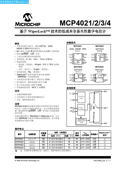
基于 WiperLock™ 技术的低成本非易失性数字电位计
特性
• 非易失性数字电位计,提供 SOT-23、 SOIC、 MSOP 和 DFN 四种封装形式
• 64 个抽头:在 A 和 B 端间利用抽头形成 63 个分级电阻 • 简单 Up/Down (U/D)协议 • 上电自动调用保存的电刷设置 • 电阻阻值:2.1 kΩ、 5 kΩ、 10 kΩ 或 50 kΩ • 低温度系数:
CS 引脚电压有三个状态 (VIL、 VIH 或 VIHH)。(注 6) 5.5V, CS = VSS, fU/D = 1 MHz 2.7V, CS = VSS, fU/D = 1 MHz 串行接口无效 (CS = VIH, U/D = VIH) TA = +25°C -202 器件 (注 1) -502 器件 (注 1) -103 器件 (注 1) -503 器件 (注 1) 无丢失代码
应用
• 电源的调整和校准 • 可在新设计中取代传统机械电位计 • 仪表、偏置和增益调节
Datasheet_EE431 高清版

L*)
Ø6 (0.24)
*) 长度请参考订货向导
Ø8
(0.31)
电路连接图
有源变送信号输出
EE431-T3xx
供电 15...35 V DC 24 V AC ±20%
EE431-T6xx
供电 20...35 V DC RL< 500 Ω 11...35 V DC RL< 50 Ω
输出: 0...10 V
-40 ℃…+110 ℃ (-40 °F...+230 °F) -40 ℃…+150 ℃ (-40 °F...+302 °F) 针对PT和NI的浸入式变速器 详见订货向导 典型< 1 mA 1) 双线 接线端子最大2x max. 2.5 mm2 (0 .004 in)2
v2.0 EE431
概述
绝缘电阻
(x)
EE431-
1) 与模拟输出无关
参数设置-模拟输出
量程 2)
单位
-40...60
(002) 公制
(M)
-20...80
(024) 非公制
(N)
0...50
(004)
0...100
(005)
32...212
(075)
-40...140
(083)
2) 可以按照要求提供其他温度输出范围
位置2 - 安装配件
浸入式安装套管 – 螺纹: ½”NPT
长度 黄铜 不锈钢
50 mm (1.97 “) 135 mm (5.31 “) 285 mm (11.22 “)
HA400111 HA400211
HA400112 HA400212
HA400113 HA400213
订货示例
无源电阻信号输出 位置1:
ERG1FGS301E中文资料(PANASONIC)中文数据手册「EasyDatasheet - 矽搜」

Type L
ERG(X)12S 6.35
ERG(X)1S 9.00
ERG(X)1F
ERG(X)2S ERG(X)2F
12.00
ERG(X)3S ERG(X)3F
15.00
ERG(X)5S ERG(X)5F
24.00
外形尺寸(mm)
φD
k
2.3
30.0
2.8
30.0
4.0
30.0
φd
0.65 0.65 0.80 0.80
120 –55 °C
100
80
60 Rated Load (%)
40
20
0 –60 –40 –20 0
70 °C
ERG(X)12S
ERG(X)1S, 1F ERG(X)2S, 2F ERG(X)3S, 3F
ERG(X)5S, 5F
130 °C
235 °C
20 40 60 80 100 120 140 160 180 200 220 240
½Z type isnon standard resistance values.
Code Type Res.Tol. Res. Value Range Code Type Res.Tol. Res. Value Range
±2 % 0.1 to 0.91 12S
±5 % 0.1 to 0.18 Z
The first two digitsare significant figures of resistance and the third one denotes number of zerosfollowing. Decimal point isexpressed by (Ex.) 1R0 : 1.0
E34-3F3-E160中文资料(ferroxcube)中文数据手册「EasyDatasheet - 矽搜」

芯片中文手册,看全文,戳
飞磁
E型磁芯及配件
E34/14/9 (E375)
GRADE 3F3
3F35
AL (nH) 100 ±5% (1) 160 ±5% (1) 250 ±5% 315 ±5% 400 ±8% 630 ±15% 2125 ±25% 1680 ±25%
Note 1.测结合平等核心跳空一半,锁模力对于A
图3 E34/14/9线圈前:12针.
绕线数据和面产品乘产品 12针 E34/14/9线圈架
单位数
SECTIONS
最低 绕组
AREA (mm 2)
标称 绕组
WIDTH (mm)
1
102
16.5
平均 长研究
TURN (mm)
69.0
0.65 21.9
27.2 max.
2.15 min.
AREA
产品
阂 x仙 (mm 4)
GRADE 3C81
3C90
3C91 3C92 3C94 3C96
AL (nH)
100 ±5% (1) 160 ±5% (1) 250 ±5% 315 ±5% 400 ±8% 630 ±15% 3200 ±25% 100 ±5% (1) 160 ±5% (1) 250 ±5% 315 ±5% 400 ±8% 630 ±15% 2440 ±25% 3200 ±25% 1850 ±25% 2440 ±25% 2125 ±25%
线圈架
对于 E34/14/9线圈前通用数据
参数 线圈架材料 最大工作温度
规范
聚酰胺(PA6.6),玻璃纤维增强,阻燃按照 “UL 94-HB” ; UL文件编号E41938(M) 130 °C, “IEC 60085”, B类
PE-65856NL;中文规格书,Datasheet资料

Electrical Specifications @ 25°C - Operating Temperature 0°C to +70°C RoHS Compliant Part Number PE-65664NL PE-65779NL PE-65856NL PE-65966NL PE-65967NL PE-65968NL PE-65969NL PE-68629NL Turns Ratio (±2%) 1:2CT 1:4CT 1:1.73CT 1:1 1:1 1:2CT 1:2CT 1:1 OCL Primary (μH MIN) 35 150 50 40 40 19 19 40 OCL @ -40�C (μH MIN) 20 LL Cw/w (pF MAX) 10 15 12 10 10 10 10 5 Bandwidth 75 System (MHzTYP) .60-300 .200-340 .200-340 .250-500 .250-500 Isolation Voltage (Vrms MIN) 1500 1500 1500 1500 1500 1500 1500 3000 Package/ Schematic QC-1/B THT QC-1/B THT LC-1/C THT LC-1/E THT LS-1/E SMT LS-1/C SMT LC-1/C THT HC-1/A THT Primary Pins 2-6 2-6 4-6 4-6 4-6 4-6 4-6 1-5
USA 858 674 8100
1
Germany 49 7032 7806 0
Singapore 65 6287 8998
Shanghai 86 21 62787060
China 86 755 33966678