AD7276_7277_7278
AD转换器芯片

ADC10D1000CIUT中文资料
这次有幸调试了国半公司一款双通道,8位,1.5G(单通道最高3G)采样率的超高速ADC,芯片型号ADC08D1500。
与普通高速芯片不同的是这款芯片的输出拥有DDR模式。
结构框图如下
专业供应E2V高速AD/DA采样芯片、DMUX多路分解器,高可靠性微处理器:
超高速模数转换器AD9446及其应用
0 引言
AD9446是ADI公司推出的16 bit模数转换芯片,它具有100 Msps的采样速率(是其它同类产品的10倍),同时能在基带内提供90dBc的SFDR和80 dBfs的SNR。
对于采用数字时间采样的频率域和时间域高性能测试和丈量应用,AD9446可将孔径抖动降低至60 fs(飞秒),而同类ADC 产品一般为120 fs~140 fs。
此外,AD9446还能提供很高的精度,并具有+0.5LSB的典型16 bit 微分线性误差(DNL)和±3LSB的典型16 bit积分线性误差(INL)。
由于AD9446的并行低电压差分信号(LVDS)输出中包括一个输出时钟信号,故可简化连接到数字处理器的接口,同时能降低数字噪声耦合返回到ADC内核的可能性。
AD9446采用100引脚TQFP/EP塑料表面贴装无铅封装。
该芯片需3.3 V/5.0 V电源和一个低电压差分输进时钟。
但不需要外部参考源。
Msps的采样速率。
隔离电源模块常用芯片

隔离电源模块常用芯片
隔离电源模块是电子设备电路中常用的一种电源模块。
它能够有效地隔离输入输出之间的电气信号,防止电路中出现潜在的接地故障和电压干扰。
在隔离电源模块中,常用的芯片有以下几种:
1. LT8300:这是一种高效率隔离型DC/DC转换器芯片,能够在输入电压范围内实现高达92%的转换效率。
它支持多种输入电压和输出电压,并具有过热保护和短路保护功能。
2. ADuM3190:这是一种高速隔离型数字隔离器芯片,能够在高达1 Mbps的数据速率下实现高精度的信号隔离。
它支持多种输入电压和输出电压,并具有电磁干扰和电压浪涌保护功能。
3. CS8122:这是一种高精度隔离型电流传感器芯片,能够实现高达±200A的电流测量范围。
它支持多种输入电压和输出电压,并具有过载保护和短路保护功能。
4. ISO1540:这是一种高速隔离型数字隔离器芯片,能够在高达100 Mbps的数据速率下实现高精度的信号隔离。
它支持多种输入电压和输出电压,并具有电磁干扰和电压浪涌保护功能。
以上是隔离电源模块中常见的芯片,它们能够为电子设备提供高效、精确、可靠的隔离电源解决方案。
- 1 -。
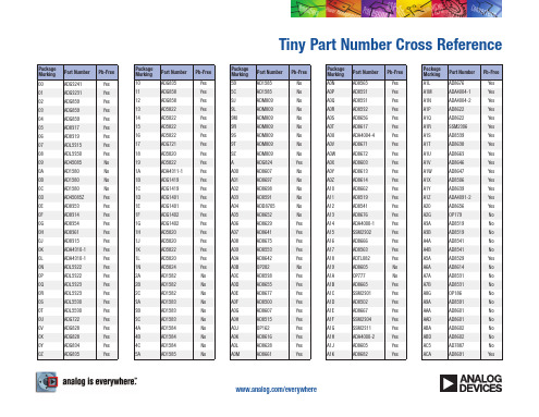
ADI公司AD转换器列表

All A/D ConvertersPrice* (1000 pcs.) Part#Resolution # Chan Throughput InterfaceFull Pwr BW AutomotiveQuery ParameterAD6672111250MSPS LVDS350M44.2AD9634-170121170MSPS350MAD9642-170141170MSPS350MAD9648142125MSPS650MAD7608188200KSPS Par; Ser; S20.5AD9434-370121370MSPS1GAD948481500MSPS Par1G36AD9613-170122170MSPS400MAD9643-170142170MSPS400MAD729112822.2KSPS I2C/Ser 2-W30M 3.9AD928482250MSPS Par700M25AD928682500MSPS Par500M36AD72981281MSPS SPI30M 3.9AD7298-11081MSPS SPI30M 2.55AD9467-200161200MSPSAD964114180MSPS Ser780M26.35AD7606168200KSPS Par; Ser; S15.7AD7606-4164200KSPS Par; Ser; S10.2AD7606-6166200KSPS Par; Ser; S12.65AD7607148200KSPS Par; Ser; S12.96AD9644-155142155MSPS780MAD9650-105162105MSPS500MAD9961102100MSPS Par25.75AD9963122100MSPS Par29.5AD9261-10161160MSPS10MAD9266-2016180MSPS700MAD665912280MSPS Par700M29.84AD7195244 4.8KSPS Ser; SPI 6.9AD9262162160MSPS 2.5MAD9269-2016220MSPS700MAD6657114200MSPS LVDS; Par800M129.71AD7170121125SPS Ser; SPI950mAD7171161125SPS Ser; SPI 1.15AD7194248 4.8KSPS Ser; SPI 6.4AD762616110MSPS LVDS; Ser95M34.95AD7985161 2.5MSPS Ser; SPI19M21AD9255-105141105MSPS650MAD9265-105161105MSPS650MAD9609-2010120MSPS700MAD9629-2012120MSPS700MAD9649-2014120MSPS700MAD7193244 4.8KSPS Ser; SPI 5.4AD9204-2010220MSPS700MAD9251-2014220MSPS700M10M40.8AD9267162LVDS; NibblAD927612880MSPS LVDS; Ser62AD7191243120SPS Ser; SPI 3.8AD7192244 4.8KSPS Ser; SPI 4.9AD7357142 4.25MSPS Ser; SPI110M Yes10.81AD7889126105KSPS I2C/Ser 2-W 1.69 AD79861812MSPS Ser; SPI19M29.95 AD9258-105142105MSPS650MAD9268-105162105MSPS650MAD7147A1613111SPS I2C/Ser 2-W 1.25 AD76251616MSPS LVDS; Ser100M29.95 AD559012161MSPS Ser; SPI8.2M19.5 AD7156122100SPS I2C/Ser 2-W 1.25 AD7190244 4.8KSPS Ser; SPI 5.9 AD73521223MSPS Ser; SPI110M 5.5 AD73561225MSPS Ser; SPI110M7.89 AD7699168500KSPS Ser; SPI14M7.99 AD7879126105KSPS I2C/Ser 2-W 1.69 AD9239-170124170MSPS780MAD9272-4012840MSPS100MAD9273-2512825MSPS70MAD72621221MSPS 1.7MAD7401A16120MSPS Ser 3.8 AD7656-1166250KSPS Par; Ser; S4.5M12.45 AD7657-1146250KSPS Par; Ser; S4.5M10.29 AD7658-1126250KSPS Par; Ser; S4.5M8.37 AD7682164250KSPS Ser; SPI 1.7M 6.01 AD7689168250KSPS Ser; SPI 1.7M 5.99 AD7949148250KSPS Ser; SPI 1.7M 4.04 AD7152122200SPS I2C/Ser 2-W 1.97 AD7153121200SPS I2C/Ser 2-W 1.77 AD72641421MSPS 1.7MAD7400A16110MSPS Ser 3.5 AD9230-11111200MSPS LVDS; Par700M36.43 AD71481684SPS I2C/Ser 2-W 1.21 AD7294129200KSPS I2C/Ser 2-W9.83 AD7991124140KSPS I2C/Ser 2-W3.4M 3.22 AD7995104140KSPS I2C/Ser 2-W14M 1.8 AD799984140KSPS I2C/Ser 2-W14M 1.35 AD71471613111SPS I2C/Ser 2-W Yes 1.28 AD7150122200SPS I2C/Ser 2-W 1.37 AD7151121100SPS I2C/Ser 2-W 1.37 AD7983161 1.33MSPS Ser; SPI20.19 AD7984181 1.33MSPS Ser; SPI28.29 AD9600-105102105MSPS650MAD9601-200101200MSPS700MAD9626-170121170MSPS700MAD9627-105122105MSPS650MAD9627-11-1112105MSPS650MAD73661241MSPS Ser; SPI35M 5.99 AD7366-5122500KSPS Ser; SPI35M 5.09 AD73671441MSPS Ser; SPI35M 6.98 AD7367-5142500KSPS Ser; SPI35M 6.08 AD7764241312KSPS Ser; SPI10.1 AD7765241156KSPS Ser; SPI8.56 AD7766241128KSPS Ser 6.02 AD7767241128KSPS Ser8.6AD9640-105142105MSPS650MAD986912180MSPS Par53M18.27 AD7785203470SPS Ser; SPI 4.25 AD79821811MSPS Ser; SPI10M23.28 AD9211-200101200MSPS700MAD986810180MSPS Nibble; SerAD714316843.5SPS I2C/Ser 2-W 1.25 AD7631181250KSPS Par; Ser; S45M29.8 AD7634181670KSPS Byte; Par; 45M31.83 AD7693161500KSPS Ser; SPI9M18.22 AD774724145.5SPS I2C/Ser 2-W 4.66 AD79521411MSPS Par; Ser; S45M10.99 AD9230-170121170MSPS700MAD7610161250KSPS Par; Ser; S650K13.05 AD7612161750KSPS Par; Ser; S45M29.45 AD79511411MSPS Byte; Par; 45M11.12 AD9212-4010840MSPS325MAD9222-4012840MSPS325MAD925214850MSPS LVDS; Ser325M54.65 AD9254141150MSPS Par650M55.66 AD7142161427.8SPS I2C/Ser 2-W 1.37 AD76221612MSPS Byte; Par; 50M21.95 AD7691181250KSPS Ser; SPI14.67 AD7795166470SPS Ser; SPI 4.45 AD7796161123SPS Ser; SPI 2.78 AD7797241123SPS Ser; SPI 3.39 AD7829-1882MSPS Par10M 3.74 AD925914450MSPS LVDS; Ser315M45.54 AD928784100MSPS LVDS; Ser295M14.17 AD9460-105161105MSPS615MAD73291381MSPS Ser; SPI20M 6.33 AD740116120MSPS Ser 3.8 AD7643181 1.25MSPS Byte; Par; 50M19.5 AD7656166250KSPS Par; Ser; S12M12.45 AD7657146250KSPS Par; Ser; S12M10.29 AD7658126250KSPS Par; Ser; S12M8.37 AD7690181400KSPS Ser; SPI9M19.73 AD9219-4010440MSPS315MAD9228-4012440MSPS315MAD9233-105121105MSPS650MAD9246-105141105MSPS650MAD9461161130MSPS Par615M65.78 AD7321132500KSPS Ser; SPI22M 3.04 AD73221321MSPS Ser; SPI22M 4.81 AD7323134500KSPS Ser; SPI22M 3.66 AD73241341MSPS Ser; SPI22M 5.82 AD7327138500KSPS Ser; SPI22M 3.99 AD740016110MSPS Ser 3.550M29.33 AD76411812MSPS Byte; Par;AD72731013MSPS Ser; SPI 3.8 AD72741213MSPS Ser; SPI 6.58 AD73281381MSPS Ser; SPI22M 6.33AD9237-2012120MSPS500MAD9445-105141105MSPS615MAD9446-100161100MSPS540MAD72761213MSPS Ser; SPI55M 1.85 AD72771013MSPS Ser; SPI74M 1.75 AD7278813MSPS Ser; SPI74M 1.65 AD76211613MSPS Byte; Par; 50M30.31 AD7623161 1.33MSPS Byte; Par; 50M19.95 AD7760241 2.5MSPS Par 1.35M24.9 AD7946141500KSPS Ser; SPI9M7.46 AD6654141Par270M78.75 AD726512121MSPS Ser; SPI33M3AD726612122MSPS Ser; SPI33M 4.31 AD7686161500KSPS Ser; SPI9M12.14 AD7687161250KSPS Ser; SPI2M9.06 AD7688161500KSPS Ser; SPI9M15.13 AD774524190SPS I2C/Ser 2-W 4.66 AD774624290SPS I2C/Ser 2-W 5.01 AD7942141250KSPS Ser; SPI2M 4.81 AD9229-5012450MSPS400MAD66502421MSPS Ser20.64 AD7798163470SPS Ser; SPI 3.85 AD7799243470SPS Ser; SPI 4.4 AD7933104 1.5MSPS Byte; Par20M 3.54 AD7934124 1.5MSPS Byte; Par20M7.19 AD7934-6124625KSPS Par 4.66 AD799212279KSPS I2C/Ser 2-W 3.04 AD9248-2014220MSPS500MAD7683161100KSPS Ser; SPI 5.82 AD7684161100KSPS Ser; SPI 6.58 AD7694161250KSPS Ser; SPI9M 6.07 AD7792163470SPS Ser; SPI 4.04 AD7793243470SPS Ser; SPI 5.16 AD7794246470SPS Ser; SPI 5.87 AD7877129125KSPS Ser 2.15 AD7938128 1.5MSPS Byte; Par20M7.44 AD7938-6128625KSPS Par 4.91 AD7939108 1.5MSPS Byte; Par20M 3.8 AD7993104188KSPS I2C/Ser 2-W11M 1.91 AD7994124188KSPS I2C/Ser 2-W11M 3.29 AD799710879KSPS I2C/Ser 2-W 2.13 AD799812879KSPS I2C/Ser 2-W 3.54 AD9216-105102105MSPS300MAD92898465MSPS Ser400M10.52 AD944414180MSPS Par650M32.69 AD948181250MSPS Par750M16.19 AD7685161250KSPS Ser; SPI2M 6.58 AD7940141100KSPS Ser; SPI7M 4.15 AD948081250MSPS LVDS; Par750M18.2 AD7787242120SPS Ser; SPI284AD7911102250KSPS Ser; SPI8.5M 2.02 AD79121021MSPS Ser; SPI13.5M 2.78AD7666161500KSPS Par; Ser; S12M913M11.01 AD76671611MSPS Par; Ser; SAD7680161100KSPS Ser; SPI8M 5.31 AD9411101170MSPS LVDS; Par700M36.38 AD74401011MSPS Ser; SPI20M 2.53 AD74411011MSPS Ser; SPI20M 2.53 AD7450A1211MSPS Ser20M 4.4 AD74511211MSPS Ser; SPI20M 4.3 AD7452121555KSPS Ser; SPI20M 2.99 AD7453121555KSPS Ser; SPI20M 2.39 AD7457121100KSPS Ser; SPI20M 2.07 AD7651161100KSPS Par; Ser; S800K7.54 AD7652161500KSPS Par; Ser; S12M9.52 AD7661161100KSPS Par; Ser; S820K7.97 AD9861-5010250MSPS30MAD986312250MSPSAD986510180MSPS Par53M10.07 AD986612180MSPS Nibble53M18.77 AD76531611MSPS Par; Ser; S12M11.64 AD7674181800KSPS Byte; Par; 26M28.29 AD7678181100KSPS Byte; Par; 900K19.43 AD7679181570KSPS Byte; Par; 26M19.5 AD778816116.6SPS Ser; SPI 2.01 AD778924116.6SPS Ser; SPI 2.99 AD7790161120SPS Ser; SPI28 2.99 AD7791241120SPS Ser; SPI28 3.88 AD9864241375KSPS Ser; SPI10.07 AD7466121200KSPS Ser; SPI 3.2M 2.38 AD7467101200KSPS Ser; SPI 3.2M 1.92 AD746881200KSPS Ser; SPI 3.2M 1.16 AD773924815.1KSPS Ser; SPI29K7.74 AD8006616424MSPS Byte 6.13 AD9215-105101105MSPS300MAD923612180MSPS Par16.7 AD924514180MSPS Par500M11.01 AD987812429MSPS Par85M13.68 AD76551641MSPS Par; Ser; S10M9.56 AD7725161900KSPS Par; Ser350K8.95 AD773224215.4KSPS Ser; SPI14K8.6 AD773424415.4KSPS Ser; SPI14K8.6 AD7908881MSPS Ser; SPI8.2M Yes 1.87 AD7910101250KSPS Ser; SPI13.5M 1.77 AD79181081MSPS Ser; SPI8.2M Yes 3.29 AD7920121250KSPS Ser; SPI13.5M 2.07 AD7927128200KSPS Ser; SPI8.2M Yes 2.83 AD79281281MSPS Ser; SPI8.2M Yes 4.81 AD9238-2012220MSPS500MAD9244-4014140MSPS750MAD74851411MSPS Ser40M9.1110M15.61 AD7654164500KSPS Par; Ser; SAD773824815.4KSPS Ser; SPI14K7.86 AD7904841MSPS Ser; SPI8.2M Yes 1.57AD986010264MSPS Par140M13.9 AD986212264MSPS Par140M30.11 AD7476A1211MSPS Ser; SPI13.5M Yes 4.05 AD7477A1011MSPS Ser; SPI 6.5M Yes 2.53 AD7478A81 1.2MSPS Ser; SPI13.5M Yes960m AD74821213MSPS Par40M7.03 AD74841413MSPS Par40M12.14 AD987912529MSPS Par12.12 AD74501211MSPS Ser20M 4.05 AD9430-170121170MSPS700MAD6645-105141105MSPS270MAD6645-MIL14180MSPS ParAD749012161MSPS Ser; SPI1M 6.02 AD7650161570KSPS Par; Ser; S18M7.59 AD76771611MSPS Par; Ser15.8M33.35 AD78661241MSPS Ser; SPI12M 6.02 AD7675161100KSPS Par; Ser; S3.9M12.14 AD7676161500KSPS Par; Ser; S3.9M25.25 AD7709164105SPS Ser; SPI25 3.94 AD778224219.79SPS Ser; SPI 4.3 AD778324119.79SPS Ser; SPI 4.3 AD9433-105121105MSPS750MAD9874241541.5KSPSSer15.14 AD76711611MSPS Par; Ser; S9.6M28.29 AD77081610 1.365KSPSSer; SPI300 4.03 AD77182410 1.365KSPSSer; SPI300 5.3 AD7719246105SPS Ser; SPI258.87 AD9218-105102105MSPS300MAD1328012280MSPS Par50MAD74951211MSPS Ser; SPI8.3M 5.25 AD7663161250KSPS Par; Ser; S800K12.14 AD7665161570KSPS Par; Ser; S3.6M19.23 AD9235-2012120MSPS500MAD1046514265MSPS Par100M757.46 AD74751211MSPS Ser8.3M 4.3 AD74921211MSPS10MAD10200122105MSPS Par250MAD155524216KSPS Byte; Ser5K74.61 AD155624216KSPS Byte; Ser5K24.86 AD73360L16664KSPS Ser4K 5.82 AD7843124125KSPS Ser 1.16 AD7873126125KSPS Ser 1.95 AD7898121220KSPS Ser 4.7M 5.03 AD7899141400KSPS Par 4.5M10.02 AD9214-105101105MSPS300MAD9410101210MSPS Par500M53.1 AD7478811MSPS Ser; SPI 6.5M960m AD7660161100KSPS Par; Ser; S820K818M18.87 AD7664161570KSPS Par; Ser; SAD922612165MSPS Par750M20.5 AD6644-4014140MSPS250MAD7336016664KSPS Ser4K 6.34 AD7470101 1.75MSPS Par20M 3.19 AD7472121 1.5MSPS Par20M 6.33 AD7707163500SPS Ser; SPI131 4.88 AD920310140MSPS Par350M 3.8 AD9432-105121105MSPS500MAD7865144350KSPS Par3M14.67 AD7888128125KSPS Ser; SPI 2.5M 3.9 AD9054A-13581135MSPS350MAD9288-10082100MSPS475MAD7729152270.8KSPSSer96K9.11 AD7887122125KSPS Ser; SPI 2.5M Yes 3.09 AD7894141200KSPS Ser7.5M8.05 AD974164200KSPS Ser; SPI1M26.72 AD9283-10081100MSPS475MAD660011220MSPS Par450M38.96 AD7705162500SPS Ser; SPI131 4.17 AD7706163500SPS Ser; SPI131 4.3 AD7723161 1.2MSPS Par; Ser460K23.28 AD7856148285KSPS Ser; SPI10.02 AD7863144175KSPS Par7M14.67 AD905110160MSPS Par130M 6.96 AD922412140MSPS Par120M12.19 AD922512125MSPS Par105M14.47 AD664012165MSPS Par300M37.61 AD7339812MSPS Par 1.024M7.94 AD7730L242600SPS Ser; SPI23.48.89 AD7827811MSPS SerAD7864124520KSPS Par3M13.81 AD920110220MSPS Par245M 5.01 AD9260161 2.5MSPS Par1M44.42 AD92818228MSPS Par245M 3.91 AD772016112.5MSPS Ser90.6K8.51 AD7731243 6.4KSPS Ser; SPI31.610.28 AD7811104350KSPS Ser 3.08 AD7812108350KSPS Ser Yes 3.34 AD7822812MSPS Par10M 3.45 AD7825842MSPS Par 3.61 AD9054AS81200MSPS Byte; ParAD7730242 1.2KSPS Ser46.8K9.98 AD7813101400KSPS Byte 2.98 AD781981200KSPS Par 2.29 AD92808132MSPS Par300M 2.18 AD977161100KSPS Ser 1.5K14.91 AD977A161200KSPS Ser1M22.03 AD7810101350KSPS Ser 2.73 AD782381200KSPS Ser 2.29 AD920010120MSPS Par300M 2.53 AD924014110MSPS Par70M18.37 AD9241141 1.25MSPS Par25M9.46 AD976161100KSPS Par700K14.91AD7851141333KSPS20MAD7862124250KSPS Par3M11.13 AD7895121192KSPS Ser 5.01 AD92431413MSPS Par40M11.69 AD1024212240MSPS Par60MAD9057-408140MSPS120MAD90598260MSPS Par120M13.23 AD7854121200KSPSAD9221121 1.5MSPS Par25M7.74 AD92231213MSPS Par40M7.74 AD7721161468.75KSPS P ar; Ser229.2K11.13 AD7859-200128200KSPSAD786111728.6KSPS Par12.75 AD7891128500KSPS Par; Ser14.93 AD9042S121AD922012110MSPS Par60M 6.12 AD90666260MSPS Par100MAD7715161500SPS Ser; SPI200 5.89 AD7853A/B121200KSPSAD7858-200128200KSPSAD87610120MSPS Par150M 3.65 AD77142451KSPS Ser; SPI2628.38 AD7896121100KSPS Ser 4.27 AD7716224 2.2KSPS Ser58434.43 AD7892-1-50121500KSPSAD7890128117KSPS Ser10.32 AD677161100KSPS Ser1M25.4 AD7893121117KSPS Ser10.02 AD676161100KSPS Par1M34.82 AD7710242 1.028KSPSSer26917.4 AD7711242 1.028KSPSSer26918.43 AD7712242 1.028KSPSSer26915.89 AD7713243205SPS Ser5318.88 AD77032014KSPS Ser; SPI18.07 AD77011614KSPS Ser15.21 AD788012166KSPS Par16.03 AD7821811MSPS Par100K9.16 AD7711A2421KSPS Ser262AD6644-6514165MSPS250MAD6645-8014180MSPS270MAD7262-5122500KSPS 1.7MAD7264-5142500KSPS 1.7MAD7492-5121 1.25MSPS10MAD7492-4121400KSPS10MAD7851K141285KSPS20MAD7851A141333KSPS20MAD7853L121100KSPSAD7854L-100121100KSPSAD7854-200121200KSPSAD7858L-100128100KSPSAD7859L-100128100KSPSAD7892-2-50121500KSPSAD9057-608160MSPS120M AD9057-808180MSPS120M AD9204-4010240MSPS700M AD9204-6510265MSPS700M AD9204-8010280MSPS700M AD9211-250101200MSPS700M AD9211-300101300MSPS700M AD9212-6510865MSPS325M AD9214-6510165MSPS300M AD9214-8010180MSPS300M AD9215-6510165MSPS300M AD9215-8010180MSPS300M AD9216-6510265MSPS300M AD9216-8010280MSPS300M AD9218-80102105MSPS300M AD9218-4010240MSPS300M AD9218-6510265MSPS300M AD9219-6510465MSPS315M AD9222-6512865MSPS325M AD9222-5012850MSPS325M AD9228-6512465MSPS315M AD9229-6512465MSPS400M AD9230-250121250MSPS700M AD9230-210121210MSPS700M AD9233-125121125MSPS650M AD9233-8012180MSPS650M AD9235-4012120MSPS500M AD9235-6512165MSPS500M AD9237-4012140MSPS500M AD9237-6512165MSPS500M AD9238-6512265MSPS500M AD9238-4012240MSPS500M AD9239-210124210MSPS780M AD9239-250124250MSPS780M AD9244-6514165MSPS750M AD9246-125141125MSPS650M AD9246-8014180MSPS650M AD9248-4014240MSPS500M AD9248-6514265MSPS500M AD9251-4014240MSPS700M AD9251-6514265MSPS700M AD9251-8014280MSPS700M AD9255-125141125MSPS650M AD9255-8014180MSPS650M AD9258-8014280MSPS650M AD9258-125142125MSPS650M AD9262-10162160MSPS10M AD9262-5162160MSPS5M AD9265-8016180MSPS650M AD9265-125161125MSPS650M AD9266-6516165MSPSAD9266-8016180MSPSAD9269-6516265MSPS700M AD9269-4016240MSPS700M AD9269-8016280MSPS700M AD9271-4012840MSPSAD9271-5012850MSPSAD9272-6512865MSPS100M AD9272-8012880MSPS100M AD9273-5012850MSPS70M AD9273-4012840MSPS70M AD9283-508150MSPS475M AD9283-808180MSPS475M AD9288-408240MSPS475M AD9288-808280MSPS475M AD9430-210121210MSPS700M AD9432-8012180MSPS500M AD9433-125121125MSPS750M AD9445-125141125MSPS615M AD9446-8016180MSPS325M AD9460-8016180MSPS615M AD9467-250161250MSPSAD9600-150102150MSPS650M AD9600-125102105MSPS650M AD9609-8010180MSPS700M AD9609-6510165MSPS700M AD9609-4010140MSPS700M AD9613-250122250MSPS400M AD9613-210122210MSPS400M AD9626-250121250MSPS700M AD9626-210121170MSPS700M AD9627-8012280MSPS650M AD9627-150122150MSPS650M AD9627-125122125MSPS650M AD9627-11-1112150MSPS650M AD9629-6512165MSPS700M AD9629-4012140MSPS700M AD9629-8012180MSPS700M AD9634-250121250MSPS350M AD9634-210121170MSPS350M AD9640-8014280MSPS650M AD9640-125142125MSPS650M AD9640-150142150MSPS650M AD9642-210141210MSPS350M AD9642-250141250MSPS350M AD9643-210142210MSPS400M AD9643-250142250MSPS400M AD9644-8014280MSPS780M AD9648-125142125MSPS650M AD9648-105142105MSPS650M AD9649-6514165MSPS700M AD9649-8014180MSPS700M AD9649-4014140MSPS700M AD9650-6516265MSPS500MAD9861-8010280MSPS30Ms.)。
ADI芯片简称对照表
Part Number
ADG835 ADG858 ADG858 AD5822 AD5822 AD5822 AD5822 ADG721 AD5820 AD5822 ADA4311-1 ADG1419 ADG1419 ADG1401 ADG1401 ADG1402 ADG1402 AD5820 AD5820 AD5822 AD5820 AD5824 AD1582 AD1582 AD1582 AD1583 AD1583 AD1583 AD1584 AD1584 AD1584 AD1585
Pb-Free
Yes Yes Yes Yes Yes Yes Yes Yes Yes Yes Yes Yes Yes Yes Yes Yes Yes Yes Yes Yes Yes No No Yes Yes Yes Yes Yes Yes Yes Yes Yes
Package Marking A1L A1M A1N A1P A1Q A1R A1S A1T A1U A1V A1W A1X A1Y A1Z A20 A2G A3A A3B A4A A4B A5A A6A A7A A7B A8G A9A AAA AAD ABA ABD AC5 ACA
Package Marking 00 01 02 03 04 05 06 07 08 09 0A 0B 0C 0D 0E 0F 0G 0H 0J 0K 0L 0N 0P 0Q 0R 0S 0T 0U 0V 0X 0Y 0Z
Part Number
ADG3241 ADG3231 ADG859 ADG859 ADG859 AD8317 AD8319 ADL5315 ADL5350 AD45085 AD1580 AD1580 AD1580 AD45085Z AD8353 AD8314 AD8354 AD8361 AD8315 ADA4310-1 ADA4310-1 ADL5322 ADL5322 ADL5323 ADL5323 ADL5530 ADL5530 ADG722 ADG828 ADG828 ADG834 ADG835
艾тон电子变频驱动器产品介绍说明书

V/Hz Energy Savings Percentage
Eaton - Active Energy Control Competitor 1 Competitor 2 Competitor 3
35
40
45
50
55
Frequency (Hz)
• Active Energy Control - minimizes energy losses in your motor by dynamically adjusting V/Hz curve to optimize efficiency
• Compare Functionality • PC Control Online Operate
Mode
© 2013 Eaton Corporation. All rights reserved.
13
Energy Saving Functionality
Percentage
10.0% 8.0% 6.0% 4.0% 2.0% 0.0% -2.0% 30 -4.0%
• Easy to Use PC Based Drive Software Configuration Tool
• Provides Parameter Description, Min, Max, and Default Values
• Monitoring and Data Logging Capabilities
© 2013 Eaton Corporation. All rights reserved.
Electrical Wholesalers
End Users Maintenance, Repair, and Operations (MRO) Opportunities
华声高压包与王牌高压包型号及代换(精品)

123/4679
1319 · BSC24-2626S 37-FCA001-EAEOD 王牌
129/3456710
1324 · BSC29-0163C 王牌 创维 29" 彩显双聚焦
1210/4567
1354 · BSC29-0104C/5132-051429-13 王牌 显示器架
123/4679
1376 · BSC29-0184F 37-SC2901-84FOX 王牌 显架
12810/359
1521 · BSC29-0107B 37-SC2901-07BX 王牌
1210/3479
1587 · BSC24-2670S 37-FCO002-FBB1D 王牌 29”骨架
123/4679
1588 · BSC29-0141T 5132-051434-39 王牌 29”骨架
123/4579
2410/5689
1015 · BSC 27-0134 王牌 2516D
12810/359
1019 · BSC 27-0106A 27-0106C 王牌 29"
14பைடு நூலகம்0/25689
1030 · 27-0166A /37-BSC270-1661X 王牌 2502D
1410/5689
1064 · 29-0153 37-BSC290-153(01)王牌 2980 双聚焦
1284 · BSC29-0179B 王牌 29"
1210/3479
1290 · BSC29-0176-T 王牌 29" 像显示器架
123/4567910
1312 · BSC29-0107C 37-SC2901-0700 王牌 双聚焦
ANALOG DEVICES EE-246 数据手册

Engineer-to-Engineer NoteEE-246aTechnical notes on using Analog Devices DSPs, processors and development tools**********************************************************************************Or visit our on-line resources /ee-notes and /processorsInterfacing AD7276 High-Speed Data Converters to ADSP-21262 SHARC® ProcessorsContributed by Aseem Vasudev Prabhugaonkar and Jagadeesh RayalaRev 1 – October 5, 2004Copyright 2004, Analog Devices, Inc. All rights reserved. Analog Devices assumes no responsibility for customer product design or the use or application of customers’ products or for any infringements of patents or rights of others which may result from Analog Devices assistance. All trademarks and logos are property IntroductionThis application note explains how to interface AD7276 high-speed data converters to ADSP-21262 SHARC® processors. This application note also provides example code to demonstrate how the SHARC processor's serial ports (SPI and SPORTs) can be programmed to receive data from AD7276 devices in core and DMA modes. The power-down scheme for AD7276 ADCs between conversions in DMA mode is also described.About AD7276/7277/7278 ADCsThe AD7276/AD7277/AD7278 devices are 12-, 10-, and 8-bit, high-speed, low-power, successive-approximation ADCs, respectively. The parts operate from a single 2.35 V to 3.6 V power supply and feature throughput rates up to 3 million samples per second (MSPS).The conversion process and data acquisition are controlled using the /CS signal and the serial clock, allowing the devices to interface with variety of microprocessors or DSPs. The input signal is sampled on the falling edge of /CS , and the conversion is also initiated at this point. There are no pipeline delays associated with the part.The AD7276/AD7277/AD7278 ADCs use advanced design techniques to achieve very low power dissipation at high throughput rates.The reference for the part is taken internally from VDD. This allows the widest dynamic input range to the ADC. Thus, the analog input range for the part is from 0 V to VDD. The conversion rate is determined by the serial clock SCLK.AD7276/7277/7278 Product Highlights3 MSPS ADCs in a 6-lead TSOT packagePin compatible to AD7476/7477/7478 and AD7476A/7477A/7478A partsHigh throughput with low power consumptionFlexible power / serial clockspeedmanagementThe conversion rate is determined by the serial clock. Increasing the serial clock speed reduces the conversion time. This reduces average power consumption while in power-down mode (i.e., while not converting). The part also features a power-down mode to maximize power efficiency at lower throughput rates. Current consumption is 1 µA max in power-down mode.Reference derived from the power supplyNo pipeline delayThe parts feature a standard successive-approximation ADC with accurate control of the sampling instant via a /CS input and once-off conversion control.AD7276/7277/7278 A/D ApplicationsAD7276/7277/7278 applications include:Battery-Powered SystemsPersonal Digital AssistantsMedical InstrumentsMobile CommunicationsInstrumentation and Control SystemsData Acquisition SystemsHigh-Speed ModemsOptical SensorsAbout ADSP-21262 ProcessorsThe ADSP-21262 is the first member of the third-generation of SHARC programmable processors. A range of applications such as high-quality audio and automotive entertainment systems, voice recognition, medical appliances and measurement devices benefit from the ADSP-21262 processor’s integration of large on-chip memory with a wide variety of peripherals—thereby speeding time to market and keeping costs low.The ADSP-21262 derivative, which is based on the SHARC processor core, supports execution of 32-bit fixed-point and 32/40-bit floating-point arithmetic formats. With its core running at 200 MHz (5-ns instruction cycle time), the ADSP-21262 processors are capable of executing complex Fast Fourier Transform (FFT) operations—a 1024-point complex FFT in 46 µs, more than 2.6 times faster than comparatively priced processors. In audio applications, the single-instruction, multiple-data (SIMD) mode effectively doubles the processor's performance. The ADSP-21262 processor is designed with the highest level of integration, including 2 Mbits of on-chip dual-ported SRAM and 4 Mbits of mask-programmable ROM memory. This large amount of on-chip dual-ported memory enables sustained processor and I/O performance without the need for external memory. System I/O is achieved through six full-duplex serial ports, four timers, a 16-bit parallel port, a serial peripheral interface (SPI), 22 zero-overhead Direct Memory Access (DMA) channels delivering fast data transfers without processor intervention, and an innovative Digital Applications Interface (DAI) offering complete software control through its Signal Routing Unit (SRU).AD7276-to-ADSP-21262 Interface This application note uses an AD7276 high-speed data converter for the interface. The other converters in this family (AD7277 and AD7278) are functionally identical. The ADC has a serial interface for DSPs and micro-controllers to transfer the 12-bit digitized data. The ADC supports SPI (Serial Peripheral Interface) and SPORT (DSP Serial Port interface) protocols. ADSP-21262 processors can connect to AD7276 ADCs over their SPI or SPORT interfaces.The serial interface of AD7276 comprises three signals:/CS Chip Select is an active low input. This signal initiates A-to-D conversion and framesthe serial data transfer.SDATA The AD7276 drives conversion results onto this pin. The data bits are clocked out onthe falling edge of the serial clock.SCLK Serial clock is an input to the ADC.The converter clocks the data bits out on thefalling serial clock edges.The falling edge on /CS puts track-and-hold in to hold mode and also initiates conversion. For compatibility with a 16-bit word length supported by SPI, the ADC outputs 16 bits. The first two bits (zeros) are followed by 12 valid data bits and two zero bits in the end of the serial data stream. Though the ADC data is 12 bits wide, every word is transferred as a 16-bit word. This helps since the SPI word length in ADSP-21262 processor is configurable as 8, 16, or 32 bits only. When interfaced to a serial port, themode mode. These two mode is that WL16 bit in the . Refer toWith CPHASE=1Refer to the In CPHASE=1, bringing /CS that the /CSoperation. Data is sampled on the clock's rising edges.Figure 6. SPORT Early Frame Sync ModeLate Frame Sync OptionWhen programmed for late frame sync option, configure the frame sync as an active low frame sync. Data can be sampled at the serial clock's rising or falling edges. Figure 7 shows timing details in the core mode of operation. Again, data is sampled on the clock's rising edges. Figure 7. SPORT Late Frame Sync ModeSummaryAs seen in this application note, you can interface ADSP-21262 and AD7276 gluelessly and use a variety of interface methods and modes.AppendixRefer to the code in the attached ZIP file for various modes of operation.References[1]ADSP-21262 DSP Hardware Reference Manual. Rev 2.0, January 2004. Analog Devices, Inc.[2]AD7276 Preliminary Technical Data Sheet. Rev PrF, June 2004. Analog Devices, Inc.[3]ADSP-21262 DSP Evaluation System Board Schematics. Analog Devices, Inc. Document HistoryRevision DescriptionRev 1 – October 05, 2004by Aseem Vasudev Prabhugaonkar Initial Release。
NI 9220 16 AI, ±10 V, 16 Bit, 100 kS s ch Simultan
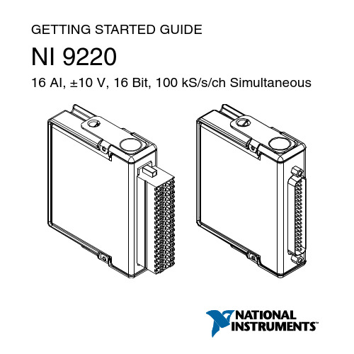
GETTING STARTED GUIDENI 922016 AI, ±10 V, 16 Bit, 100 kS/s/ch SimultaneousThis document explains how to connect to the NI 9220. In this document, the NI 9220 with spring terminal and the NI 9220 with DSUB are referred to inclusively as the NI 9220.Note Before you begin, complete the software andhardware installation procedures in your chassisdocumentation.Note The guidelines in this document are specific tothe NI 9220. The other components in the system mightnot meet the same safety ratings. Refer to thedocumentation for each component in the system todetermine the safety and EMC ratings for the entiresystem.Caution Electrostatic Discharge (ESD) can damagethe NI 9220 with spring terminal. To prevent damage,use industry-standard ESD prevention measures duringinstallation, maintenance, and operation.Safety GuidelinesOperate the NI 9220 only as described in this document.2| | NI 9220 Getting Started GuideCaution Do not operate the NI 9220 in a manner notspecified in this document. Product misuse can result ina hazard. You can compromise the safety protectionbuilt into the product if the product is damaged in anyway. If the product is damaged, return it to NI forrepair.Hazardous Voltage This icon denotes a warningadvising you to take precautions to avoid electricalshock with the NI 9220 with spring terminal. Safety VoltagesConnect only voltages that are within the following limits:NI 9220 with Spring Terminal Isolation Voltages Channel-to-channel NoneChannel-to-earth groundContinuous250 Vrms,Measurement Category IIWithstand up to 4,000 m 3,000 Vrms, verified by a 5 s dielectric withstand testNI 9220 Getting Started Guide| © National Instruments| 3Measurement Category II is for measurements performed on circuits directly connected to the electrical distribution system. This category refers to local-level electrical distribution, such as that provided by a standard wall outlet, for example, 115 V for U.S. or 230 V for Europe.Caution Do not connect the NI 9220 with springterminal to signals or use for measurements withinMeasurement Categories III or IV.NI 9220 with DSUB Safety VoltagesChannel-to-COM±30 V maximumIsolationChannel-to-COM NoneChannel-to-earth groundContinuous60 VDC, MeasurementCategory IWithstand up to 2,000 m 1,000 Vrms, verified by a 5 s dielectric withstand testMeasurement Category I is for measurements performed on circuits not directly connected to the electrical distribution system 4| | NI 9220 Getting Started Guidereferred to as MAINS voltage. MAINS is a hazardous live electrical supply system that powers equipment. This category is for measurements of voltages from specially protected secondary circuits. Such voltage measurements include signal levels, special equipment, limited-energy parts of equipment, circuits powered by regulated low-voltage sources, and electronics.Caution Do not connect the NI 9220 with DSUB tosignals or use for measurements within MeasurementCategories II, III, or IV.Safety Guidelines for Hazardous VoltagesYou can connect hazardous voltages only to theNI 9220 with spring terminal. Do not connect hazardous voltages to the NI 9220 with DSUB.If hazardous voltages are connected to the device, take the following precautions. A hazardous voltage is a voltage greater than 42.4 Vpk voltage or 60 VDC to earth ground.Caution Ensure that hazardous voltage wiring isperformed only by qualified personnel adhering to localelectrical standards.NI 9220 Getting Started Guide| © National Instruments| 5Caution Do not mix hazardous voltage circuits andhuman-accessible circuits on the same module.Caution Ensure that devices and circuits connected tothe module are properly insulated from human contact.Caution When module terminals are hazardousvoltage LIVE (>42.4 Vpk/60 VDC), you must ensurethat devices and circuits connected to the module areproperly insulated from human contact. You must usethe NI 9940 connector backshell kit to ensure that theterminals are not accessible.Safety Guidelines for Hazardous LocationsThe NI 9220 is suitable for use in Class I, Division 2, Groups A, B, C, D, T4 hazardous locations; Class I, Zone 2, AEx nA IIC T4 and Ex nA IIC T4 hazardous locations; and nonhazardous locations only. Follow these guidelines if you are installing the NI 9220 in a potentially explosive environment. Not following these guidelines may result in serious injury or death.Caution Do not disconnect I/O-side wires orconnectors unless power has been switched off or thearea is known to be nonhazardous.6| | NI 9220 Getting Started GuideCaution Do not remove modules unless power hasbeen switched off or the area is known to benonhazardous.Caution Substitution of components may impairsuitability for Class I, Division 2.Caution For Division 2 and Zone 2 applications,install the system in an enclosure rated to at least IP54as defined by IEC/EN 60079-15.Caution For Division 2 and Zone 2 applications,connected signals must be within the following limits. Capacitance0.2 µF maximumSpecial Conditions for Hazardous Locations Use in Europe and InternationallyThe NI 9220 has been evaluated as Ex nA IIC T4 Gc equipment under DEMKO 12 ATEX 1202658X and is IECEx UL 14.0089X certified. Each NI 9220 is marked II 3G and is suitable for use in Zone 2 hazardous locations, in ambient temperatures of -40 °C ≤ Ta ≤ 70 °C. If you are using the NI 9220 in Gas Group IIC hazardous locations, you must use the device in an NI chassis thatNI 9220 Getting Started Guide| © National Instruments| 7has been evaluated as Ex nC IIC T4, Ex IIC T4, Ex nA IIC T4, or Ex nL IIC T4 equipment.Caution You must make sure that transientdisturbances do not exceed 140% of the rated voltage.Caution The system shall only be used in an area ofnot more than Pollution Degree 2, as defined inIEC/EN 60664-1.Caution The system shall be mounted in anATEX/IECEx-certified enclosure with a minimumingress protection rating of at least IP54 as defined inIEC/EN 60079-15.Caution The enclosure must have a door or coveraccessible only by the use of a tool.Electromagnetic Compatibility Guidelines This product was tested and complies with the regulatory requirements and limits for electromagnetic compatibility (EMC) stated in the product specifications. These requirements and limits provide reasonable protection against harmful interference 8| | NI 9220 Getting Started Guidewhen the product is operated in the intended operational electromagnetic environment.This product is intended for use in industrial locations. However, harmful interference may occur in some installations, when the product is connected to a peripheral device or test object, or if the product is used in residential or commercial areas. To minimize interference with radio and television reception and prevent unacceptable performance degradation, install and use this product in strict accordance with the instructions in the product documentation.Furthermore, any changes or modifications to the product not expressly approved by National Instruments could void your authority to operate it under your local regulatory rules.Caution To ensure the specified EMC performance ofthe NI 9220 with DSUB, the length of all I/O cablesmust be no longer than 30 m (100 ft).Caution To ensure the specified EMC performance,operate this product only with shielded cables andaccessories. Do not use unshielded cables oraccessories unless they are installed in a shieldedenclosure with properly designed and shielded input/NI 9220 Getting Started Guide| © National Instruments| 9output ports and connected to the product using ashielded cable. If unshielded cables or accessories arenot properly installed and shielded, the EMCspecifications for the product are no longer guaranteed. Special Conditions for Marine ApplicationsSome products are Lloyd’s Register (LR) Type Approved for marine (shipboard) applications. To verify Lloyd’s Register certification for a product, visit /certification and search for the LR certificate, or look for the Lloyd’s Register mark on the product.Caution In order to meet the EMC requirements formarine applications, install the product in a shieldedenclosure with shielded and/or filtered power andinput/output ports. In addition, take precautions whendesigning, selecting, and installing measurement probesand cables to ensure that the desired EMC performanceis attained.10| | NI 9220 Getting Started GuidePreparing the EnvironmentEnsure that the environment in which you are using the NI 9220 meets the following specifications.Operating temperature(IEC 60068-2-1, IEC 60068-2-2)-40 °C to 70 °COperating humidity (IEC 60068-2-78)10% RH to 90% RH, noncondensingPollution Degree2Maximum altitudeFor NI 9220 withspring terminal4,000 mFor NI 9220 withDSUB2,000 mIndoor use only.Note Refer to the device datasheet on /manualsfor complete specifications.NI 9220 Getting Started Guide| © National Instruments| 11NI 9220 Pinout12| | NI 9220 Getting Started GuideGrounded Differential ConnectionsNI 9220 Getting Started Guide| © National Instruments| 13Floating Differential ConnectionsConnect the negative lead to COM through a 1 MΩ resistor to keep the signal source within the common-mode voltage range. The NI 9220 does not read data accurately if the signal source is outside of the common-mode voltage range.14| | NI 9220 Getting Started GuideSingle-Ended ConnectionsConnect the ground signal to COM to keep the signal source within the common-mode voltage range.NI 9220 Connection Guidelines•Make sure that devices you connect to the NI 9220 are compatible with the module specifications.•You must use 2-wire ferrules to create a secure connection when connecting more than one wire to a single terminal on the NI 9220 with spring terminal.NI 9220 Getting Started Guide| © National Instruments| 15•For the NI 9220 with spring terminal, push the wire into the terminal when using a solid wire or a stranded wire with aferrule.•For the NI 9220 with spring terminal, open the terminal by pressing the push button when using stranded wire without a ferrule.High-Vibration Application ConnectionsIf your application is subject to high vibration, NI recommends that you use the NI 9940 backshell kit to protect connections to the NI 9220 with spring terminal.Overvoltage ProtectionThe NI 9220 provides overvoltage protection for each channel.Note Refer to the device datasheet on /manualsfor more information about overvoltage protection.16| | NI 9220 Getting Started GuideWhere to Go NextLocated at /manuals NI 9220 Getting Started Guide | © National Instruments | 17Worldwide Support and ServicesThe NI website is your complete resource for technical support. At /support, you have access to everything from troubleshooting and application development self-help resources to email and phone assistance from NI Application Engineers. Visit /services for NI Factory Installation Services, repairs, extended warranty, and other services.Visit /register to register your NI product. Product registration facilitates technical support and ensures that you receive important information updates from NI.A Declaration of Conformity (DoC) is our claim of compliance with the Council of the European Communities using the manufacturer’s declaration of conformity. This system affords the user protection for electromagnetic compatibility (EMC) and product safety. You can obtain the DoC for your product by visiting /certification. If your product supports calibration, you can obtain the calibration certificate for your product at /calibration.18| | NI 9220 Getting Started GuideNI corporate headquarters is located at11500 North Mopac Expressway, Austin, Texas, 78759-3504. NI also has offices located around the world. For telephone support in the United States, create your service request at /support or dial 1 866 ASK MYNI (275 6964). For telephone support outside the United States, visit the Worldwide Offices section of /niglobal to access the branch office websites, which provide up-to-date contact information, support phone numbers, email addresses, and current events.NI 9220 Getting Started Guide| © National Instruments| 19Refer to the NI Trademarks and Logo Guidelines at /trademarks for information on NI trademarks. Other product and company names mentioned herein are trademarks or trade names of their respective companies. For patents covering NI products/technology, refer to the appropriate location: Help»Patents in your software, the patents.txt file on your media, or the National Instruments Patent Notice at /patents. Y ou can find information about end-user license agreements (EULAs) and third-party legal notices in the readme file for your NI product. Refer to the Export Compliance Information at /legal/export-compliance for the NI global trade compliance policy and how to obtain relevant HTS codes, ECCNs, and other import/ export data. NI MAKES NO EXPRESS OR IMPLIED WARRANTIES AS TO THE ACCURACY OF THE INFORMATION CONTAINED HEREIN AND SHALL NOT BE LIABLE FOR ANY ERRORS. U.S. Government Customers: The data contained in this manual was developed at private expense and is subject to the applicable limited rights and restricted data rights as set forth in FAR 52.227-14, DFAR 252.227-7014, and DFAR 252.227-7015.© 2017 National Instruments. All rights reserved.378023A-01Jan17。
- 1、下载文档前请自行甄别文档内容的完整性,平台不提供额外的编辑、内容补充、找答案等附加服务。
- 2、"仅部分预览"的文档,不可在线预览部分如存在完整性等问题,可反馈申请退款(可完整预览的文档不适用该条件!)。
- 3、如文档侵犯您的权益,请联系客服反馈,我们会尽快为您处理(人工客服工作时间:9:00-18:30)。
CONTROL LOGIC
SCLK SDATA CS
04903-001
Table 1. Part Number AD7276 AD7277 AD7278 AD72741 AD72731
GND
Figure 1.
Resolution 12 10 8 12 10
Package 8-Lead MSOP 6-Lead TSOT 8-Lead MSOP 6-Lead TSOT 8-Lead MSOP 6-Lead TSOT 8-Lead MSOP 8-Lead TSOT 8-Lead MSOP 8-Lead TSOT
GENERAL DESCRIPTION
The AD7276/AD7277/AD7278 are 12-/10-/8-bit, high speed, low power, successive approximation analog-to-digital converters (ADCs), respectively. The parts operate from a single 2.35 V to 3.6 V power supply and feature throughput rates of up to 3 MSPS. The parts contain a low noise, wide bandwidth trackand-hold amplifier that can handle input frequencies in excess of 55 MHz.
11/09—Rev. A to Rev. B Changes to Table 2............................................................................ 3 Changes to Table 3............................................................................ 5 Changes to Table 4............................................................................ 7 Changes to Ordering Guide .......................................................... 27
AD7276/AD7277/AD7278
TABLE OF CONTENTS
Features .............................................................................................. 1 General Description ......................................................................... 1 Functional Block Diagram .............................................................. 1 Product Highlights ........................................................................... 1 Revision History ............................................................................... 2 Specifications..................................................................................... 3
3 MSPS, 12-/10-/8-Bit ADCs in 6-Lead TSOT
AD7276/AD7277/AD7278
FUNCTIONAL BLOCK DIAGRAM
VDD
12-/10-/8-BIT
SUCCESSIVE
VIN
T/H
APPROXIMATION
ADC
AD7276/ AD7277/ AD7278
approximation ADC with accurate control of the sampling instant via a CS input and once-off conversion control.
Rev. C
Information furnished by Analog Devices is believed to be accurate and reliable. However, no responsibility is assumed by Analog Devices for its use, nor for any infringements of patents or other rights of third parties that may result from its use. Specifications subject to change without notice. No license is granted by implication or otherwise under any patent or patent rights of Analog Devices. Trademarks and registered trademarks are the property of their respective owners.
The AD7276/AD7277/AD7278 use advanced design techniques to achieve very low power dissipation at high throughput rates.
The reference for the part is taken internally from VDD. This allows the widest dynamic input range to the ADC; therefore, the analog input range for the part is 0 to VDD. The conversion rate is determined by the SCLK.
maximum power efficiency at low throughput rates. 5. Reference derived from the power supply. 6. No pipeline delay. The parts feature a standard successive
AD7276 Specifications................................................................. 3 AD7277 Specifications................................................................. 5 AD7278 Specifications................................................................. 7 Timing Specifications—AD7276/AD7277/AD7278 ............... 8 Timing Examples........................................................................ 10 Absolute Maximum Ratings.......................................................... 11 ESD Caution................................................................................ 11 Pin Configurations and Function Descriptions ......................... 12 Typical Performance Characteristics ........................................... 13 Terminology .................................................................................... 15
FEATURES
Throughput rate: 3 MSPS Specified for VDD of 2.35 V to 3.6 V Power consumption
12.6 mW at 3 MSPS with 3 V supplies Wide input bandwidth
70 dB SNR at 1 MHz input frequency Flexible power/serial clock speed management No pipeline delays High speed serial interface
The conversion process and data acquisition are controlled using CS and the serial clock, allowing the devices to interface with microprocessors or DSPs. The input signal is sampled on the falling edge of CS, and the conversion is also initiated at this point. There are no pipeline delays associated with the part.