gm_mast5
mSquad系统用户手册说明书

The mSquad System is a quickly-deployable set of mobile multi-gas meters that communicate wirelessly to a Squad leader up to 0.8 km (0.5 miles) distant. The system is ideal for Hazmat Response, firefighters, temporary venue protection, etc. An mSquad consists of one Head monitor (MP400H) and up to 7 Soldier monitors (MP400S) that communicate with each other. Each 4- or 5-gas monitor has options for a full range of sensors for toxicgases, oxygen (O 2), combustibles (LEL) and carbon dioxide (CO 2). The MP400S can also have a PID for volatile organic compounds (VOCS). In addition to high gas concentration alarms, all Squad units receive any Man-Down alarms to notify them remotely of a worker in distress. All the Squad monitors are Class I Division I certified to op-erate in hazardous zones. The entire mSquad is mobile, running on batteries for up to 12 hours. The MP400S and MP400H have rugged construction and easy-to-learn 2-button operation.Features, Functions and Benefits•Remote, wireless real-time readings and alarms including Man-down•Up to 8 remote 4- or 5-gas monitors•Up to 0.8 km (0.5 miles) distance to Squad Head •All mSquad units alarm if any one unit has an alarm condition•Mobile system operation•12-hour continuous operation on single Li-ion battery charge.•USB Micro cable for battery charging and direct PC communication•Wide selection of sensor typesMobile Wireless Multi-Gas Team Warning SystemVer 1.04MP400SMP400SMP400HMP400SMP400SMP400SMP400SMP400SAdvanced Test Equipment Corp. 800-404-ATEC (2832)Santa Clara • Houston • Shanghai • • HQ Office: (408) 320-1266•1-866-mPower7SpecificationsMP400S and MP400H SpecificationsSize 5.7 x 3.3 x 1.7 in (140 x 84 x 42 mm) w/o Antenna Weight15.5 oz (435 g)SensorsInterchangeable and field-replceable: PID forVOCs (MP400S only), EC for Toxic & O 2, Pellistor for LEL, and NDIR for LEL, Vol% & CO 2 Response time (t90) • 15 s (LEL/CO/H 2S/O 2) MP400S • 20 s (LEL/CO/H 2S/O 2) MP400H • Others vary up to 120 sSampling MP400S - Internal pump; MP400H - Diffusion Battery 8-36 hr (depending on sensors and pump installed) Direct Readout• Real-time reading of gas concentration• PID measurement gas and correction factor, • Battery status• STEL, TWA, peak and minimum values • Man-Down alarm on/offDisplay 128 x 128 graphical LCD, 1.77 x 1.73 in (45 x 44 mm), with LED backlight and a uto “flip” screen Range 0.8 km (1/2 mile) between MP400H and MP400S Frequency ISM band (902-928 MHz) FCC Part 15 approved Calibration Zero and span calibration. Single or multiple sen-sor simultaneous calibration settingsMonitors Up to 8 per mSquad (1 MP400H plus 7 MP400S) Alarms• Audible (95 dB @ 30 cm)• Visual (flashing bright red LEDs) • Vibration• On-screen indication of alarm conditions • Man-Down alarm and manual Panic alarmWireless Alarm Notification Alarm on any monitor sent to all others in mSquad for 5 seconds, then remains on at MP400H Datalogging Continuous datalogging (6 months for 4 sensors at 1-minute intervals, 24 hours/day and 7 days/week) Direct PC Comm and Charging USB cable for charging, data download, instrument setup and firmware upgrades on PC or 100-240V AC charger, or CaliCase. Temperature -4° to 122°F (-20° to 50°C)Humidity 0% to 95% Relative humidity (non-condensing) IP Rating IP-65 MP400S (pump); IP-67 MP400H (diffusion) SafetyCertificationsClass I, Div 1, Group ABCD T4, -20°C ≤ T amb ≤ +50°CIECEx Ex ia IIC T4 GaII 1G Ex ia IIC T4 Ga European Conformity EMC/RFI EMC directive: 2014/30/EUWarranty• 2 Years on instruments• 2 Years on sensors for pellister LEL, and O 2, CO, H 2S, SO 2, HCN, NO, NO 2, and PH 3 EC sensors • 1 Year on other sensorsSensor OptionsSensorRange ResolutionPID0-200 ppm 0-2000 ppm 0.01 ppm 0.1 ppm Oxygen (O 2) Lead WoolLead-Free0-30%Vol 0-30%Vol 0.1%Vol 0.1%Vol Combustibles (LEL%) 0-100%LEL 1%LEL Hydrocarbons (Vol%) 0-100%Vol0.1%Vol Dual-Range LEL%/Vol% 0-100%Vol1%LELCO 2 (Carbon Dioxide) 0-50000 ppm 100 ppmCO (Carbon Monoxide) 0-1000 ppm 1 ppm H 2S (Hydrogen Sulfide)0-100 ppm 0-1000 ppm0.1 ppm 1 ppm CO + H 2S CO H 2S 0-500 ppm0-200 ppm 1 ppm 0.1 ppm SO 2 + H 2S SO 2 H 2S 0-20 ppm 0-100 ppm0.1 ppm 0.1 ppm NH 3 (Ammonia) 0-100 ppm 0-500 ppm 1 ppm 1 ppm Cl 2 (Chlorine)0-50 ppm 0.1 ppm ClO 2 ( Chlorine Dioxide) 0-1 ppm 0.01 ppm H 2 (Hydrogen)0-1000 ppm 1 ppm HCl (Hydrogen Chloride) 0-15 ppm 0.1 ppm HF (Hydrogen Fluoride) 0-20 ppm 0.1 ppm HCN (Hydrogen Cyanide) 0-100 ppm0.1 ppm NO (Nitric Oxide) 0-250 ppm 1 ppm NO 2 (Nitrogen Dioxide) 0-20 ppm 0.1 ppm PH 3 (Phosphine) 0-20 ppm 0-1000 ppm 0.01 ppm 1 ppm SO 2 (Sulfur Dioxide) 0-20 ppm 0-100 ppm 0.1 ppm 0.1 ppm C 2H 4O (Acetaldehyde) 0-20 ppm 0.1 ppm ETO (Ethylene Oxide)0-100 ppm0.1 ppm CH 3SH (Methyl Mercaptan) 0-10 ppm 0.1 ppm THT (Tetrahydrothiophene) 0-40 ppm0.1 ppm* Due to ongoing research and product improvement, specifications are subject to change without notice *Typical Battery Run TimesSensor Configuration Monitor PumpTime NDIRLEL/VOL/O 2/CO/H 2SMP400H MP400S MP400S NoneOff On36 hr 36 hr 24 hr NDIRLEL/VOL/PID/O 2/CO+H 2S MP400H MP400S MP400S NoneOff On 20 hr 20 hr 15 hr PellistorLEL/O 2/CO/H 2S MP400H MP400S MP400S None Off On 12 hr 12 hr 10 hr PellistorLEL/PID/O 2/CO+H 2SMP400H MP400S MP400S None Off On10 hr 10 hr 8 hr。
LGplc应用指令手册
第五章应用指令5.1 数据传送指令5-15.1.1 MOV, MOVP, DMOV, DMOVP ..................................................... 5-15.1.2 CMOV, CMOVP, DCMOV, DCMOVP .......................................... 5-35.1.3 GMOV, GMOVP .................................................................................. 5-65.1.4 FMOV, FMOVP ................................................................................... 5-85.1.5 BMOV, BMOVP ................................................................................ 5-10 5.2 转换指令5-125.1.1 BCD, BCDP, DBCD, DBCDP ......................................................... 5-125.2.2 BIN, BINP, DBIN, DBINP .............................................................. 5-15 5.3 比拟指令5-185.3.1 CMP, CMPP, DCMP, DCMPP ...................................................... 5-185.3.2 TCMP, TCMPP, DTCMP, DTCMPP .............................................. 5-225.3.3 LD ( =, >, <, >=, <=, <> ) ..................................................... 5-245.3.4 AND ( =, >, <, >=, <=, <>) ................................................... 5-255.3.5 OR ( =, >, <, >=, <=, <>) ...................................................... 5-27 5.4 增加/减少运算5-295.4.1 INC, INCP, DINC, DINCP ............................................................. 5-295.4.2 DEC, DECP, DDEC, DDECP .......................................................... 5-31 5.5 回转指令5-345.5.1 ROL, ROLP, DROL, DROLP .......................................................... 5-345.5.2 ROR, RORP, DROR, DRORP ....................................................... 5-375.5.3 RCL, RCLP, DRCL, DRCLP ............................................................ 5-395.5.4 RCR, RCRP, DRCR, DRCRP .......................................................... 5-425.6 移位指令5-445.6.1 BSFT, BSFTP ...................................................................................... 5-445.6.2 WSFT, WSFTP ................................................................................... 5-465.6.3 SR.......................................................................................................... 5-48 5.7 交换指令5-515.7.1 XCHG, XCHGP, DXCHG, DXCHGP ............................................ 5-51 5.8 BIN 算术指令5-535.8.1 ADD, ADDP, DADD, DADDP ...................................................... 5-535.8.2 SUB, SUBP, DSUB, DSUBP .......................................................... 5-555.8.3 MUL, MULP, DMUL, DMULP ..................................................... 5-575.8.4 MULS, MULSP, DMULS, DMULSP ............................................ 5-605.8.5 DIV, DIVP, DDIV, DDIVP ............................................................... 5-635.8.6 DIVS, DIVSP, DDIVS, DDIVSP .................................................... 5-65 5.9 BCD算术指令5-685.9.1 ADDB, ADDBP, DADDB, DADDBP ........................................... 5-685.9.2 SUBB, SUBBP, DSUBB, DSUBBP ................................................ 5-705.9.3 MULB, MULBP, DMULB, DMULBP ........................................... 5-745.9.4 DIVB, DIVBP, DDIVB, DDIVBP ................................................... 5-76 5.10 逻辑算术指令5-795.10.1 WAND, WANDP, DWAND, DWANDP ..................................... 5-795.10.2 WOR, WORP, DWOR, DWORP ................................................. 5-825.10.3 WXOR, WXORP, DWXOR, DWXORP ....................................... 5-845.10.4 WXNR, WXNRP, DWXNR, DWXNRP ...................................... 5-86 5.11 数据处理指令5-885.11.1 SEG, SEGP ......................................................................................... 5-895.11.2 ASC, ASCP ......................................................................................... 5-925.11.3 BSUM, BSUMP, DBSUM, DBSUMP .......................................... 5-945.11.4 ENCO, ENCOP .................................................................................. 5-975.11.5 DECO, DECOP ................................................................................ 5-1005.11.6 FILR, FILRP, DFILR, DFILRP ....................................................... 5-1025.11.7 FILW, FILWP, DFILW, DFILWP .................................................. 5-1055.11.8 DIS, DISP ......................................................................................... 5-1075.11.9 UNI, UNIP ........................................................................................ 5-1105.11.10 IORF, IORFP .................................................................................... 5-112 5.12 系统指令5-1145.12.1 FALS ................................................................................................... 5-1145.12.2 DUTY ................................................................................................. 5-1155.12.3 WDT, WDTP .................................................................................... 5-1185.12.4 OUTOFF ............................................................................................ 5-1205.12.5 STOP .................................................................................................. 5-121 5.13 跳转指令5-1225.13.1 JMP, JME .......................................................................................... 5-1225.13.2 CALL, CALLP, SBRT, RET ............................................................ 5-124 5.14 循环指令5-1265.14.1 FOR, NEXT ...................................................................................... 5-1275.14.2 BREAK ............................................................................................... 5-128 5.15 标志指令5-1295.15.1 STC, CLC ........................................................................................... 5-1295.15.2 CLE ..................................................................................................... 5-131 5.16 特殊模块指令5-1325.16.1 GET, GETP ........................................................................................ 5-1335.16.2 PUT, PUTP ....................................................................................... 5-135 5.17 数据连接指令5-1375.17.1 READ ................................................................................................. 5-1385.17.2 WRITE ................................................................................................ 5-1415.17.3 RGET .................................................................................................. 5-1435.17.4 RPUT .................................................................................................. 5-1475.17.5 STATUS .............................................................................................. 5-150 5.18 中断指令5-1525.18.1 EI, DI .................................................................................................. 5-1525.18.2 TDINT, IRET ..................................................................................... 5-1535.18.3 INT, IRET .......................................................................................... 5-1555.19 符号反转指令5-1565.19.1 NEG, NEGP, DNEG, DNEGP...................................................... 5-156 5.20 位接触指令5-1595.20.1 BLD, BLDN ....................................................................................... 5-1595.20.2 BAND, BANDN .............................................................................. 5-1605.20.3 BOR, BORN ..................................................................................... 5-1615.20.4 BOUT ................................................................................................. 5-1635.20.5 BSET, BRST ...................................................................................... 5-164 5.21 计算机连接模块指令5-1655.21.1 SND .................................................................................................... 5-1655.21.2 RCV .................................................................................................... 5-166 5.22 高速计数器指令5-1675.22.1 HST ..................................................................................................... 5-1675.22.2 HSC .................................................................................................... 5-170 5.23 RS-485 通讯指令5-1715.23.1 RECV .................................................................................................. 5-1725.23.2 SEND ................................................................................................. 5-1735应用指令5.1.1MOV, MOVP, DMOV, DMOVP1)功能-MOV(P) : 传送在[ S ]中的16位数据至指定的设备[ D ].16 位- DMOV(P) : 传送在指定设备[ S+1, S ]中的32位数据到指定的设备[ D+1, D ].-2) 编程举例在P020检测到一个上升沿,‘h70F3’被传送到P04。
himothink5

第三台网桥,接上电源 通电
启动过程中网桥会自动 搜索第一台的信号并连 接,并且自动设置模式 为【客户端模式】,完 成自动配对
启动过程中网桥会自动 搜索第一台的信号并连 接,并且自动设置模式 为【客户端模式】,完 成自动配对
室外网桥系列
产品技术规格
产品型号
HMSK-CPE2000
硬件规格 无线速率
主芯片:AR9344 主 频:560MHz
室外网桥系列
3
室外网桥系列
软件界面
软件界面简洁美观,功能完善,各项运行数据清晰展示,用户可以随时查看,中英文语言自由切换,真正做 到易用、好用。
室外网桥系列
自动配对功能
一、点对点模式
第一台网桥,接上电源 通电
等待设备启动完成,并 且无线信号出现,此时 设备默认模式为【网桥 模式】
二、点对多点模式
无线,信号强度指示灯
支持24V PoE供电
工作模式
支持网桥模式、客户端模式
支持语言
安全设置 系统升级方 式 功耗
软件界面支持中文/英文显示 支持Open System,WEP,WPA-PSK,WPA2-PSK等多种加密方式 支持有线或无线方式连接设备升级 〈8W
Байду номын сангаас
外壳
ABS进口阻燃材料,IP67防尘防水
第二台网桥,接上电源 通电
启动过程中网桥会自动 搜索第一台的信号并连 接,并且自动设置模式 为【客户端模式】,完 成自动配对
第一台网桥,接上电源 通电
等待设备启动完成,并 且无线信号出现,此时 设备默认模式为【网桥 模式】
第二台网桥,接上电源 通电
启动过程中网桥会自动 搜索第一台的信号并连 接,并且自动设置模式 为【客户端模式】,完 成自动配对
5000系列操作演示

5000系列操作演示一、硬件配置:1.多功能高速交换模块(FEM):用于提供高速的数据转发和处理功能。
支持多种接口类型,包括千兆以太网、万兆以太网和光纤通信。
可根据实际需求插入不同类型的FEM模块。
2.冗余电源模块(PSM):用于提供设备的电源备份,以确保设备在电源中断时的正常运行。
3.热插拔风扇模块(FM):用于散热和保持设备的正常工作温度。
4.控制处理器模块(CPM):用于管理和控制设备的各个模块,确保设备的正常运行。
二、软件功能:1.网络配置和管理:5000系列设备支持通过命令行界面(CLI)和图形用户界面(GUI)进行网络的配置和管理。
管理员可以通过配置界面轻松地设置网络参数、开启和关闭接口、管理子网、进行路由配置等操作。
2. 安全性:5000系列设备支持各种安全特性,包括访问控制列表(ACL)、虚拟专用网(VPN)、IPSec加密、防火墙等功能,保护网络免受安全威胁。
3.服务质量(QoS):5000系列设备支持流量控制和优先级设置,确保网络中关键应用的性能,并提供带宽控制和流量监测功能。
4.路由协议:5000系列设备支持各种路由协议,包括静态路由、动态路由(如OSPF、BGP)等,以实现网络的自动化路由选择和快速故障恢复。
5. 网络扩展:5000系列设备支持网络的扩展和维护,包括虚拟局域网(VLAN)、链路聚合(LAG)和端口镜像(Port Mirroring)等功能。
三、操作演示:以下是5000系列设备的基本操作演示,包括设备的启动、登录、配置和管理。
1.设备启动:将5000系列设备连接到电源和网络,并确保连接的各模块正确安装。
按下电源按钮,设备将开始启动。
在启动过程中,可以通过连接到设备的控制台端口观察启动信息。
2.登录设备:待设备启动完毕后,使用CLI或GUI登录设备。
输入正确的用户名和密码,确认登录成功。
3.配置网络参数:使用CLI或GUI进入设备的配置界面,设置设备的IP地址、子网掩码和网关地址。
pm五轴编程案例
pm五轴编程案例在机器人编程中,五轴编程是一种常见的方法,可以实现机器人在空间中沿着不同轴向的运动和定位。
下面将以一段五轴编程案例为例,详细介绍相关参考内容。
案例描述:假设我们有一台五轴机器人,需要将一个零件从初始位置移动到目标位置,并进行旋转操作。
机器人的操作范围在指定的坐标系内,需要考虑避障和合理的路径规划。
解决方案:1. 确定坐标系和参考点:在编程之前,需要先确定机器人操作的坐标系和参考点。
坐标系一般由机器人的基座和参考点构成,可以选择机器人自身的坐标系或其他外部参考系。
参考点是标志机器人位置的点,可以是机器人底座的中心或其他固定位置。
2. 实现运动规划:机器人的运动规划可以采用不同的方法,如直线插补、圆弧插补等。
直线插补是指沿着一条直线路径进行插补,可以通过计算初始位置和目标位置之间的直线距离,以及机器人的运动速度和加速度来实现。
圆弧插补是指机器人通过一系列圆弧段的插补来实现复杂的路径规划,可以通过给定圆弧的起始点、终止点和半径来计算插补路径。
3. 考虑避障:在机器人编程中,避障是一个重要的问题。
可以通过在程序中加入避障算法来实现机器人在运动过程中的安全操作。
常用的避障算法包括路径规划算法、感知和反应算法等。
路径规划算法可以根据环境中的障碍物信息,寻找机器人的安全路径;感知和反应算法可以利用传感器信息,实时监测和避免机器人与障碍物之间的碰撞。
4. 实现旋转操作:除了直线运动,机器人还可能需要进行旋转操作。
旋转可以通过控制机器人的关节角度来实现。
例如,对于五轴机器人,可以通过调整机器人的第四轴和第五轴角度来实现旋转操作。
在编程中,需要根据旋转角度和机器人的运动范围计算旋转操作的角度范围和步进。
5. 进行调试和优化:在完成编程之后,需要对程序进行调试和优化。
可以通过机器人的仿真软件或实际设备进行验证和调试。
调试过程中可以检查机器人是否按照预期路径和速度运动,是否与障碍物发生碰撞等。
如果程序存在问题,可以进行优化,例如调整运动规划算法的参数,改进避障策略等。
MG接口配置

目录
目录
2 MG 接口配置 ...............................................................................................................................2-1
2.4.1 配置 H.248 协议的 MG 接口属性 ....................................................................................................2-4 2.4.2 配置 MGCP 协议的 MG 接口属性 .................................................................................................2-11 2.5 配置 MG 接口软件参数 ...........................................................................................................................2-16 2.5.1 配置 H.248 协议的 MG 接口软件参数...........................................................................................2-16 2.5.2 配置 MGCP 协议的 MG 接口软件参数 .........................................................................................2-20 2.6 配置 MG 接口振铃方式 ...........................................................................................................................2-23 2.7 配置 MG 接口终端分层 ...........................................................................................................................2-26 2.8 启动 MG 接口 ...........................................................................................................................................2-28
BAMAC MAST5-4C-U17 型驱动板 使用说明
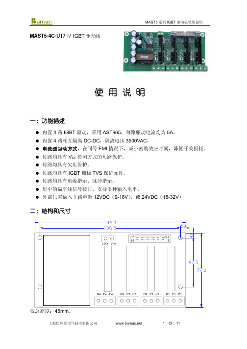
MAST5-4C-U17型IGBT 驱动板使 用 说 明一:功能描述内置4路IGBT 驱动,采用AST965,每路驱动电流均为5A 。
内置4路相互隔离DC-DC ,隔离电压3500VAC 。
电流源驱动方式,在同等EMI 情况下,减小密勒效应时间,降低开关损耗。
每路均具有V CE 检测方式的短路保护。
每路均具有欠压保护。
每路均具有IGBT 栅极TVS 保护元件。
每路均具有电源指示、脉冲指示。
集中的扁平线信号接口,支持多种输入电平。
外部只需输入1路电源12VDC (9-18V ),或24VDC (18-32V )二:结构和尺寸三:连接及说明1、扁平线引脚定义描述表序号功能号描述12 PEN 驱动输出使能,如PEN为低电平,则无论输入信号如何变化,所有驱动输出保持为负电位;PEN为高电平时,允许驱动输出为高(根据输入信号变化);PEN信号须有2mA以上的高电平驱动能力,该信号不能悬空,不使用时应连接到VCC34 PUL1 第一路信号输入(信号1输入),当PEN为高时,信号输入为高时,驱动输出正电位,信号输入为低时,驱动输出负电位。
信号输入须具有8mA以上的高电平驱动能力56 PUL2 第二路信号输入(信号2输入),当PEN为高时,信号输入为高时,驱动输出正电位,信号输入为低时,驱动输出负电位。
信号输入须具有8mA以上的高电平驱动能力78 PUL3 第三路信号输入(信号3输入),当PEN为高时,信号输入为高时,驱动输出正电位,信号输入为低时,驱动输出负电位。
信号输入须具有8mA以上的高电平驱动能力910 PUL4 第四路信号输入(信号4输入),当PEN为高时,信号输入为高时,驱动输出正电位,信号输入为低时,驱动输出负电位。
信号输入须具有8mA以上的高电平驱动能力1112空1314 GND信号输入和保护信号输出的公共负端,一般接GND1516 VS保护信号输出的公共正端,一般接VCC(3.3V、5V、12V或15V)1718 PS1 第一路保护信号输出,当检测到短路保护或欠压保护时,该引脚输出高电位。
魅玛轻型迷你PTZ控制器RM-LP5用户手册说明书
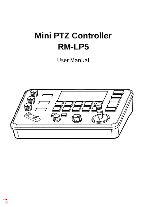
Mini PTZ Controller RM-LP5User ManualParameters & Specs Communication & Control Interface Camera Control or Operation Control Signal FormatPower Supply and ConsumptionPhysical & Others Description of Button & Knob FunctionInterface Function and Connection Diagram Upgrade Interface RS422/RS485 Interface RS232 Interface LAN Interface12V DC Power InterfaceSystem Menu Operation Instructions System Menu Function Explanation Keyboard System Menu System Setting Comm Setting Ethernet SettingPassword SettingSystem Menu Guide Products DimensionsContent2 2 2 2223 7 7788910 10 10 10 11 11 12 12 13④⑤⑪⑮①This Rotation Knob which was to adjustment the Camera Exposure Parameter or Red Gain Value, Turn Right Rotation was to changed the valued Increased, Turn Left Rotation was changed the Valued Decreased.②This Rotation Knob which was to adjustment the Camera Exposure Parameter or Blue Gain Value, Turn Right Rotation was to changed the valued Increased, Turn Left Rotation was changed the Valued Decreased.③This Rotation Knob which was to adjustment the Camera Exposure Parameter, Turn Right Rotation was to changed the valued Increased, Turn Left Rotation was changed the Valued Decreased.④LED Display, Real-time display of items and parameter values of adjusted by " knob ①".⑤LED Display, Real-time display of items and parameter values of adjusted by " knob ②".⑥LED Display, Real-time display of items and parameter values of adjusted by " knob ③".⑦Zoom Bridge KeyIt is used to control the camera to Zoom In/Out, for example, press the TELE end of the bridge key, the camera will Zoom in the TELE direction object, When you Press with more Large Pressure, then the Zoom Speed changed more Faster.⑧ Focus Function ZoonWhen the Backlight of [AUTO]Button is Light up, it means that the current focusing mode is the automatic; When the Backlight of [AUTO] Button is Light Off, it means that Current Focus Mode is changed to Manual. User can Press this button to switch the mode.[OPT key] is used to trigger the single focus of the camera.At the same time, the camera enters the one-shot auto focus mode.⑨PTZ Speed Adjustment KnobThis knob is used to adjust the speed of Camera Pan, Tlit and Zoom, with a total of 7 gears.The Current Gear will be display at Led Display. The Gear Value is more small then the pan/tilt rotation speed or the zoom speed of the camera controlled by the keyboard will be more Slowly.⑩ 2-Aixs JoystickThe joystick supports control camera to Up/Down, Left and Right movement. When the camera or keyboard menu is opened, the joystick is used to control the menu cursor Up/Down,Left/Right movement and modify parameters.⑪ Channel Button Zone[ CAM1 ] to [ CAM5 ] are shortcut keys for camera channels, which can be Freely switched and selected according to your need. When you select any camera channel, the backlight of the corresponding camera channel will be light up in green, and all the parameters and settings of the keyboard will be changed to the current Channel.Note: The communication parameters (address ID, protocol, baud rate, IP address, port number, etc.) of each channel can be set individually.Support mixed use of multiple protocols through different channel.⑫ Presets Function Zone●[ Number Keys ]SETING PRESETS :Long Press and hold the number key for 2 seconds (such as [Number key 1], when the screen displays "Set Preset 1” means that preset 1 has been saved) CALL PRESETS :Short press the preset number to be call Presets, (for example, [Number key 1],when you press the [Number key 1]the screen displays "Show Preset 1", it means that preset 1 has been call).●[ RESET Key ]TO BE CLEAR THE PRESET SETTINGPress[RESET key]+[Number key]to clear the preset position setting. After pressing the [RESET key], the green backlight starts to flash, Then press the preset number that needs to be cleared, (for example,[RESET]+ [Number key 1], at this time, the green Backlight of button of the [RESET key]stops flashing, and at the same time, “Reset Preset 1” is displayed on the screen, which means that preset 1 has been cleared.⑬ FOCUS KnobThis Knobs is using to adjustment camera’s focal length, Rotation right direction is adjustment focus length near, Rotation Left direction is adjustment focus length Far; (When User using this function, the keyboard’s Focus mode will be changed to Manual, It wasn’t available on AUTO Mode).⑭ Function Key Zone●[Menu Key]This key is to Turn ON/OFF Camera Menu, Long Press with 3secs will turn on Keyboard system Menu.●[AE MODE Key]This key is used to change the automatic exposure mode of the camera. Each time is pressed, the camera changes to different exposure mode. Under in difference of exposure mode, the corresponding functions of Knob 1, Knob 2 and Knob 3 are different. It is shown in real time on the display at the right of the knob.● [ WB MODE Key ]This Key is used to changed the White Balance of the camera. Each Time is pressed, the camera will be changed to different WB Mode.Under in difference ofWB mode, the corresponding functions of Knob 1, Knob 2 are different.The specific functions of the knobs are shown in Table 2:●[ Fn Keys ]This key is reserved for adding custom functions.The factory default state is: short press this key to send the command to enter theSub-menu of the camera, long press this key for 3 seconds to back Home Position of Camera.⑮ LED DISPLAYIt is used to display the current status information & Setting information of the keyboard in real time (including IP address, Port number, serial port address, communication protocol, Baud Rate and other information) and keyboard menu,the brightness of the display can be set through the keyboard menu.White Balance ModeKnob 1Knob 2AutoNOT USED NOT USED Manual Red GainBlue GainTable 2The interface is for upgrade of Hardware of keyboard by Laptop. Using Micro USB Cable direct connection with PC, And Upgrade by our upgrade tools software.This Interface is using to Connection with Camera by RS422 or RS485,detail connection diagram as follows pictures:③ RS232 InterfaceThis Interface is using to connection with Camera through RS232, detailThe LAN Interface is using for connection with Network switch or others.Network PTZ Camera, detail connection diagram as follows:●This interface is the Power supply interface, you can direct connection it with Power adapter; please don’t using non-original Power adapter.⑤ DC Power Supply Interface● Connect with multiple cameras by LAN interface detail connection diagram as follows:(When connecting multiple cameras, you need to set the IP of each camera separately1.Long Press [ MENU ] with 3secs will turn on Keyboard system Menu;2.The joystick swings up and down: control the system menu cursor to move up and down / change the parameters of the current menu item;3.The Joystick swings Right: enter the current menu item / save and exit the current menu item;4.The Joystick swings Left: Exist current Menu item/ No Saved and Exit current Menu item;5.Press [ MENU ]to exist System Menu;6.Press the number keys[0]~[9]: input numerical value (only valid for menu items that need to input numerical value). example IP Address or Port number setting.7.When the current value is number input, the green backlight of [CAM1]~[CAM5] is Light on, and at this time [CAM1]~[CAM5] Corresponds to the numbers 6~0 on the silk screen above the buttons.SYSTEM MENU 1.Long Press [ MENU ] with 3 secs will turn on Keyboard system Menu.2.The joystick swings up and down to control the menu cursor to move up and down SYSTEM SETTING The joystick swings up and down the Cursor to [ System Setting ], then Movement right to enter System Setting menu.● [ Language ]The Joystick swings up/down to [Language], then Movement right to enter setting. The Joystick swing up/down can changed the current Parameters setting, Swing the joystick to the right to save the current parameters and exit the language settingstate. The following menus operate setting is same.Optional Language: Chinese, English; other languages can be customized and developed according to customer needs.● [ LED Display Brigtness ]Change the brightness of the LED display: Low, Normal, High.● [ Automatically Standby ]Set the keyboard to automatically enter standby mode without any operation within a limited time.Select-able: Off, 1 minute, 2 minutes, 5 minutes, 10 minutes, 20 minutes, 30 minutes, 60 minutes.● [ Itself IP ]To setting Keyboard itself IP Address / Port Number, default IP is 192.168.1.88, default Port 52381.System Menu Operation & Explanation 1. System Setting 2. COMM Setting 3. Ethernet Setting 4. Password Setting1. Language : English2. LED Display Brigtness: Normal3. Automatically Standby: Off4. Itself IP: 192.168.001.0885. Itself Port: 523816. Factory default Setting7. About Keyboard●[ Factory default Setting ]To change the Keyboard restore to Factory default setting.● [ About Keyboard ]To review the relevant information of the keyboard, including: keyboard model, Firmware version, factory S/N and other information.●[ Address ]To set the serial communication address of the corresponding channel.If the current communication protocol is VISCA, the communication address can be selected from 1~7. If the current communication protocol is PELCO-D/P,The communication address can be selected from 1~255.●[ Baud Rate ]To set the serial communication Baud Rate of the corresponding channel.Available in: 2400, 4800, 9600, 19200, 38400bps.●[ Protocol ]To set the Serial communication Protocol of the corresponding channel ( Including Serial Communication Protocol and Internet Communication Protocol).Available in: VISCA, PELCO P/D, UDP .ETHERNET SETTINGTo move the cursor to [ Ethernet Setting ], then Movement right to enter Ethernet Setting:●[ Channel ]The available channels CAM1~5 correspond to the buttons [CAM1]~[CAM5].●[ Cam IP ]To set the Cam IP of the corresponding channel, which can be directly input through the number keys. When the number of input digits reaches 3, the cursor will automatically Jump to the next entry.●[ Port ]To set the UDP Port of the corresponding channel, it depend for the UDP Port 1. Channel: CAM1 2. Cam IP: 192.168.1.1623. Port: 52381PASSWORD SETTINGTo move the cursor to [ Password Setting ], then Movement right to enter Password :●[ Using Password ]How to Using the Password Function:To changed the Password setting is Enable;When the password function is Enable, a password is required to enter the menu.The default password is: 8888●[ Modify Password ]The user can change the password by himself. If the password is not changed, the password is the default password.Warning: Please use this function with caution. If the product cannot be used normally due to the password set by the customer, the manufacturer does not assume any responsibility.1. Using Password: Enabled2. Modify PasswordSYSTEM MENU GUIDE nguage: Chinese, EnglishProducts Dimensions The size for Mini Pro PTZ Controller is as below:(Unit of length: mm)。
- 1、下载文档前请自行甄别文档内容的完整性,平台不提供额外的编辑、内容补充、找答案等附加服务。
- 2、"仅部分预览"的文档,不可在线预览部分如存在完整性等问题,可反馈申请退款(可完整预览的文档不适用该条件!)。
- 3、如文档侵犯您的权益,请联系客服反馈,我们会尽快为您处理(人工客服工作时间:9:00-18:30)。
The isolation system has a vertical and horizontal natural frequency of 1.5 Hz. The system has adjustable vertical damping so that the isolator response can be fine-tuned in the field during acceptance testing.
-3-
Hale Waihona Puke Fabreeka International, Inc.
Fabreeka performed a dynamic and structural analysis of the mass (brackets attached) simulating the inputs from the shaker table. The bending and rigid body modes of the mass are analyzed and approved or the design is revised to meet the dynamic specifications.
A Fabreeka modal analysis of the reaction mass design includes the isolation system response to the dynamic inputs. Dynamic deflection and natural frequencies are obtained when simulating the shaker table inputs.
General Motors Proving Ground 5-Axis Multi-Axis Shaker Table (MAST)
The existing multi-axis shaker table (MAST) was installed on a concrete reaction mass without isolation.
-2-
Fabreeka International, Inc.
Four (4) isolators support the reaction mass and shaker table payload. Each isolator is 40" in height and can support 120,000 pounds.