ELMO简明使用介绍材料
Elmo TT-12i 互动白板教室配置指南说明书

With Interactive WhiteboardUSBRGB OUT To projectorRGB IN To computerUSB To computerPlug-in for AC adaptorVIDEO OUT To TV monitor Rear panel1Configureyour classroomBasic ConfigurationInstall Image Mate software AC plugsAC plugsRGB/HDMI cableHDMI OUT To projectorTo speakerWith ComputerPower on the TT-12i Zoom and FocusPress the Auto-focus button to focus after zoomingTwist the zoom knob to zoom in/out2LED lightRotateRotate the camera column close to a small object,turn the camera head horizontally to view students giving a presentation, speech, etc.Rotate the arm 180°and position camera head downward for left-handed users.34Capture and ReviewA. Insert SD card/USB flash driveC. Review saved imagesUse buttons to scroll and select.QUICK TRAINING GUIDE: TT-12i1Pause the camera image. Press again to unfreeze.Menu(see page 2)Adjust brightnessView computer desktopView document camera imageB. Capture imageTraining Video (TT-12): /tt-12-interactive-document-cameraZoomPower Adjust brightness View images/videosfrom SD card Take a picture and save to SD cardTT-12i mic records audio when recording video.View computer desktop Compare picture: Compare the live image to a saved image from the SD card.Auto-focus:Press after zoomingThe Highlight allows you to emphasize a specific area of the image. Move the highlight using arrow buttons [▲][►][▼][◄].The Mask feature lets you to hide the answer to a written problem or following along when reading text, etc. To move the mask, use [▲][►][▼][◄].Press the Scroll to zoom instantly then use [▲][►][▼][◄] to scroll around your image.5Control the TT-12i from anywhere in the classroom27Connect the TT-12i to a computer andinstall Image Mate to save images and videos to thecomputer . You can also annotate on the live image and record time-lapsephotography (set interval time in Settings beforebeginning time-lapse)Take a pictureand save to computerRecord video and time-lapse photographyRemote to control the document camera from the desktop Open previously saved filesView live imageSelect the time-lapseinterval, file format, etc.Additional Menu features6Return to live imageRecord videoStart and stop video recordingCapture students’ curiosity by applying the Mosaic feature, letting them predict the displayed object.Use Microscope mode with the Optional Microscope Attachment to display slide images for the entire class to see at once.InstallImage Mate softwarePress the Menu button tocustomize preferences and apply special modes such as Mosaic and Microscope. 1-800-947-ELMO /ElmoClassrooms /ElmoCamsDownload Image Mate at /t-12i-interactive-document-camera。
Elmo P30可移动视觉传播器说明书

Envision beauty in motionP30Visual PresenterHead ArmLampOptical 15X zoomDigital 4X zoomThe P30 is ideal for a diverse range of presentation applications – from business and research to industry and education.Elmo’s state-of-the-art technologies deliver bothmoving and still images with exceptional beauty and clarity.Capture crisp, live imagesNow you can convey presentations more effectively and inspire youraudience with vivid moving images on the big screen. With a frame rate of 20 fps, the P30 smoothly captures andreproduces moving images that can either be presented live or saved to your PC for future use.P30Visual PresenterThe P30’s advanced camera systemintegrates an 850,000-pixel progressive scan CCD pickup that’s capable of capturing not only the finest details of images — butmoving objects as well! Combined with true XGA (1,024 x 768) resolution, the P30 reproduces three-dimensional objects and subtle shades of color with unsurpassed precision.presentation with the 4X digital zoom function that can enlarge images up to 60 times when combined with the 15X optical zoom lens.free-angle camera The P30’s camera head can be rotated freely tocapture objects at preciseangles, making it easy topresent objectswith the exact look you want. And with the free-angle lamp, you also have all the flexibility you need to set ideal lighting conditions.Crystal Clear ExpressionLightweight andCompactBusiness trip reports Product demosPresentations atmedical/academic meetings Auctions for high-quality items Presentations of large A3-size documents or photosBusiness/IndustryEducation/TrainingOptionalJog DialJog Dial Optional button(optional) button that gives you the flexibility to assign a frequentlyused function to the front panel.USB 2.0SD MemoryCard slotSD Memory CardPCDigital cameraP30A3SizeSDCardNote: The cord cover pictured here is made transparent for explanatory purposes.AnnotationSplit Screen function Save video filesStill imageLive videoBundled SoftwareBundled SoftwareSetting StorageTWAINDriverWith the convenience of bundled software,creating outstanding PC presentations has never been easier.Make effective presentations – even without a PC!Other key featuresQuick and easy PC file transferring opens up a new world of possibilities.“Image Mate for Presentation”• Annotation tools let you draw lines(freehand or straight) in a variety of colors to highlight and enhance screen images, right from your PC.• Split Screen gives you a platform for comparing live video to stored images — side by side for greater visual impact.“Image Mate for Movie Creation”• Moving images can be easily saved to a PC for future use as analog RGB 850,000-pixel video files. Since files are saved in common AVI or WMV format, they can be played back effectively using Windows Media ® Player*.* AVI/WMV file playback is available with Windows Media Player versions 6.4 to 10.State presettingInstead of having to readjust the machine every time you use it, the P30 lets you store up to eight frequently used settings such as iris selection, white balance and lamp on/off. With quick and easy access to settings, your preferred adjustments are always ready to go.Slide Shooting Adapterusing the P30’s included Slide Shooting Adapter. (See the back page.)Split screen and slideshow displayImages previously saved to an SD Memory Card can be conveniently displayed as split screens (9 or 16 splits) or slideshows, enabling quick file searches and smoothoperation.A3-size shooting areacaptures a wider image field compared to the conventional B4 size.Cord coverCables are always neat and tidy thanks to the rear panel cord cover.TWAIN driverWith TWAIN compatibility, the P30 brings you the versatility to import saved image filesto commercially available photo retouching software.SD Memory Card-ready® files and digital camera images, previously saved to an SD Memory Card (sold separately) is ready to go even without a PC. Thanks to the P30’s Image Mate for Presentation software, you can output SD Memory Card data through the P30 for use in slideshowpresentations. Now with the flexibility of SD Memory Card storage, which can hold up to 2,048 image files, as well as conventional PC and camera images, the P30 provides anew dimension of presentation possibilities.ELMO CO., LTD. (Head Office and Factory)’s QMS/EMS has been registered toISO 9001:2000 & ISO 14001:2004.P30 SpecificationsProfileAccessories OptionsSlide Shooting AdapterAll dimensions in inches (mm)Rear PanelELMO’s Helping to Provide a GreenerFuture for Our ChildrenThis ELMO product complies with RoHS Directive 2002/95/EC (Restriction Of the use of certain Hazardous Substances in electronic equipment). This compliance helps to ensure a healthier and greener environment for all our children.5.6-inch color LCD monitorLM-5611AMonitor shoeMS-30H: horizontal, V: verticalDesign and specifications are subject to change without prior notice.is a trademark of ELMO COMPANY, LIMITED.SD logo is a trademark. Other brand names and product names may be trademarks or registered trademarks of their respective owners.。
ELMO PentaClass A 全功能音频解决方案说明书

All-in-one audio solutionwith analog input PentaClass AFor more information visitAll-in-one audio solutionwith analog inputTechnical Specifications360° Omnidirectional Soundfield Enjoy truly rich sounds whenever you are seated in the room.Remote control Remote control for the easy operation of the devices.Audio presets Choose voice, multimedia and music presets.Auto power off Automatic power-saving mode to save energy.1300 sqft (120 sqm) coverage Suitable for room sizes of up to 1300 ft2 ( 120 m2).AudioFrequency Response 80 Hz - 20 kHz Output 45 W @ 8 ΩLoudness 85 dB Signal to noise ratio (typical) 106 dB ConnectionsInputs 1 x AUX, 3.5 mm stereo Output 1 x AUX, 3.5 mm stereo, mixedIn the box Certes PentaClass speaker Power supply 19 V 2A Power cord Remote control with battery Fixation bracket with screws Flange Plate for false ceiling Safety wire User’s manual 23 cm24 cmELMO USA Corp. (West Coast branch)5555 Garden Grove Blvd, Suite 375, Westminster, CA 92683Tel.: 714-828-8457ELMO USA Corp.1478 Old Country Road, Plainview, NY 11803E-mail:****************,tel.:800-347-3566PentaClass ALED status indication A speci c light will illuminate on the top panel.Hi Fi Design - Plywood box Vocal sound clarity, a full range for multimedia and a rich bass for music.Easy Installation In a matter of minutes you can install the PentaClass using the supplied mount on a ceiling or wall.。
爱默生质量流量计简明使用手册(1)

爱默生质量流量计简明使用手册(1) 嘿,伙计们!今天我们要聊聊一个非常实用的东西——爱默生质量流量计。
别看它是个小小的设备,但它的用处可大了!它可以帮助我们测量液体和气体的质量流量,还可以帮助我们监测管道中的泄漏情况。
这个神奇的小玩意儿到底怎么用呢?别着急,我这就给你们讲解一下!让我们来了解一下爱默生质量流量计的基本结构。
它主要由两部分组成:一个是测量单元,另一个是显示单元。
测量单元负责测量质量流量,而显示单元则负责将测量结果显示出来。
这只是它的基本结构,实际上还有很多其他的功能等待着你去发掘哦!我们该如何正确地使用爱默生质量流量计呢?其实,方法很简单:我们需要将它安装在一个合适的位置。
一般来说,我们应该将它安装在管道的进出口处,这样才能保证它能够准确地测量到质量流量。
我们需要将它与被测流体连接起来。
这里需要注意的是,我们应该选择合适的连接方式,以免影响测量结果。
我们只需要打开电源,然后按照显示屏上的提示进行操作即可。
在使用爱默生质量流量计的过程中,我们还需要注意一些事项。
我们应该定期对设备进行校准,以确保测量结果的准确性。
我们应该注意设备的保养和维护,避免因为设备故障而导致测量结果不准确。
我们还应该学会如何处理异常情况,比如管道泄漏、设备损坏等。
只有这样,我们才能充分发挥爱默生质量流量计的作用,为我们的工作和生活带来更多的便利。
爱默生质量流量计是一个非常实用的工具,它可以帮助我们更好地了解流体的流动情况,从而为我们的工作和生活提供更多的便利。
希望我的介绍能让大家对这个神奇的小玩意儿有更深入的了解。
今天的分享就到这里啦!希望大家喜欢!下次再见啦!。
Steam-Elmo steam generator使用说明书

Standardized manualKeBPr-2019_1 Steam-ElmoDocument number: 1_2019Version:1Date:21.10.2019Writer: Tero Eerikäinen1Intended useSteam-Elmo steam generator is used in pilot hall for e.g. Marubishi fermentor sterilization and heating Centri-Therm evaporator. Also Diessel vessel is a potential target for steam generator use.2SafetyWhen sterilizing the reactor or the valves, don’t touch the metal parts without gloves, because they might be extremely hot and there is a risk of burns. Also face visor is recommended for protecting from steam and steam leaks.3Instructions3.1Water on, close bottom valves, switch main switches, fill, switch on heat Before the use, set on feed water. Water goes to a feed tank. If it is empty you may use separate hose to fill the tank. The yellow feed pump feed the water, but sometimes you may need to open the bottom screw to remove airfrom the feed line.:Check that steam drying / vessel emptying valves are closed like in the pictures below:Switch on the the long black main switch on the wall, and switch on Steam-Elmo main switch (puoliteho or täysteho). If the generator is empty, you must first wait that it willbe filled. Filling is needed to reach between the meter limits, otherwise heating is not possible to switch on:Then you can set on the Steam-Elmo heating (green push button) too. Wait until enough pressure and heat is gained. You can open for a short while the blue bottom valve to dry the steam. Then you can open the line (slowly) to the target vessel. Monitor during the use that temperature and pressure remain high enough. Sometimes there has been problems that steam generator goes off without any obvious reason. Switching on again can be done then. After finishing, if device is not to be used for some time, empty the generator vessel opening blue bottom valve.4Problem situationsIn a problem situation in which the problem cannot be solved with a separate manual (in Finnish) in pilot hall, contact Tero Eerikäinen or Jari Keto. Sometimes there has been e.g. pressure limiter swich latched, and pressing this green button in the pressure limiter after opening upper the side wall can solve a problem when no heating is possible:Following pages are copies of certain pages from manual in Finnish:。
ELMO参数下载及调整说明 20130912

ELMO参数Download及PID调整说明书(I type encoder tuning)一、下载参数:1、打开Composer 软件2、点选Open Communication Directly3、点选RS-232(选择与Elmo 连线方式)&Properties…(进入连线设定)4、设定连线的Com Port、Bit Per Second 选择19200、Parity 选择None5、开启Monitor6、将轴推至硬体左极限或下极限7、Indications Display1 点选Position8、Enter Command 写入px=0(将轴位置定为零)9、将轴来回推动于两极限中运动,再推回左极限or 下极限(测试来回重现性),若误差在+-30 内且没有累积误差,则来回重现性测试完成10、Download 参数11、打开参数文件12、设定通讯参数13、按Download 开始下载14、下载完后,设定使能输入功能及电流环增益(驱动器1V指令对应的输出安培数)参数储存,输入SV 然后按 Eenter二、I 类型编码器的调整(I:Interpolated Analog Encoder)1、与驱动器连上线后,新建一个工程;2、下一步,指定电机类型、持续电流(A)、最大速度(RPM或M/s)3、下一步,指定编码器类型和参数再下一步:4、设置系统限定5、输入功能设定(点忽略:ignore)6、输出功能设定(点忽略:ignore)7、设定调整步骤(一般整定电流环和电机换向)8、调整电流环电流环调整完成9、调整换向点RUN,马达将移动一点点OK,马达将往暂定的正方向移动点Yes 为接受刚才移动的方向为正方向;No 为设定刚才移动的方向为反向换向调整成功10、保存新建应用三、故障查询信息1、错误代码2、常用指令: IL、OL、RM、YA、AC、DC、ER、CL、XP、IL:IL[1]=0 servo onOL:OL[1]=7 Motor enable/disable(故障)YA:YA[4]=4 Feedback B 输出主编码器或模仿、编码器信号。
ELMO VP Receiver VPR-2 用户手册说明书
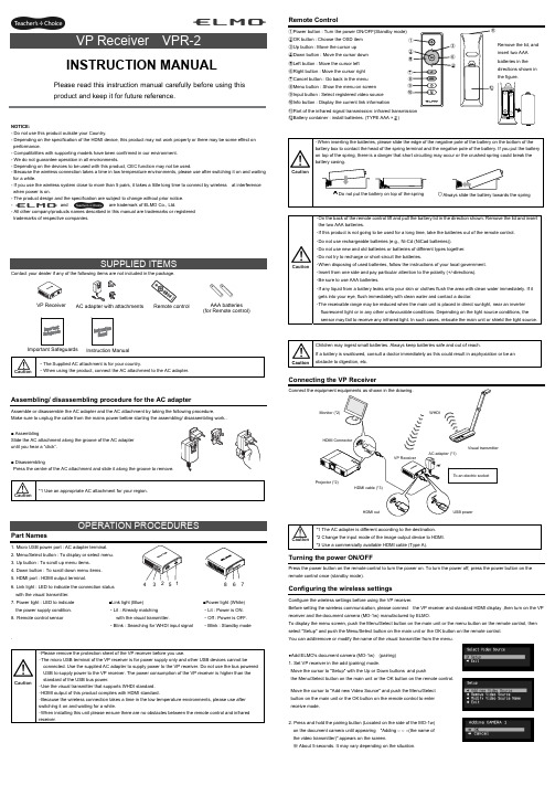
NOTICE:- Do not use this product outside your Country.- Depending on the specification of the HDMI device, this product may not work properly or there may be some effect on performance.- Compatibilities with supporting models have been confirmed in our environment. - We do not guarantee operation in all environments.- Depending on the devices to be used with this product, CEC function may not be used.- Because the wireless connection takes a time in low temperature environments, please use after switching it on and waiting for a while.- If you use the wireless system close to more than 5 pairs, it takes a little long time to connect by wireless at interference when power is on.- The product design and the specification are subject to change without prior notice. -and are trademark of ELMO Co., Ltd.- All other company/products names described in this manual are trademarks or registered trademarks of respective companies.Contact your dealer if any of the following items are not included in the package. Caution・The Supplied AC attachment is for your country.・When using the product, connect the AC attachment to the AC adapter.Assembling/ disassembling procedure for the AC adapterAssemble or disassemble the AC adapter and the AC attachment by taking the following procedure.Make sure to unplug the cable from the mains power before starting the assembling/ disassembling work..■ AssemblingSlide the AC attachment along the groove of the AC adapter until you hear a “click”.■ DisassemblingPress the centre of the AC attachment and slide it along the groove to remove. Caution *1 Use an appropriate AC attachment for your region.Part Names1. Micro USB power port : AC adapter terminal.2. Menu/Select button : To display or select menu.3. Up button : To scroll up menu items.4. Down button : To scroll down menu items.5. HDMI port : HDMI output terminal.6. Link light : LED to indicate the connection status with the visual transmitter.7. Power light : LED to indicate the power supply condition.8. Remote control sensor . Caution・Please remove the protection sheet of the VP receiver before you use.・The micro USB terminal of the VP receiver is for power supply only and other USB devices cannot beconnected. Use the supplied AC adapter to supply power to the VP receiver. Do not use the bus powered USB to supply power to the VP receiver. The power consumption of the VP receiver is higher than the standard of the USB bus power.・Use the visual transmitter that supports WHDI standard. ・HDMI output of this product complies with HDMI standard.・Because the wireless connection takes a time in the low temperature environments, please use after switching it on and waiting for a while.・When installing this unit please ensure there are no obstacles between the remote control and infrared receiver .Remote Control①Power button : Turn the power ON/OFF(Standby mode) ②OK button : Choose the OSD item ③Up button : Move the cursor up ④Down button : Move the cursor down ⑤Left button : Move the cursor left ⑥Right button : Move the cursor right ⑦Cancel button : Go back in the menu ⑧Menu button : Show the menu on screen ⑨Input button : Select registered video source ⑩Info button : Display the current link information⑪Part of the infrared signal transmission: infrared transmission⑫Battery container : install batteries. (TYPE AAA ×2)Caution・On the back of the remote control lift and pull the battery lid in the direction shown. Remove the lid and insert the two AAA batteries.・If this product is not going to be used for a long time, take the batteries out of the remote control. ・Do not use rechargeable batteries (e.g., Ni-Cd (NiCad batteries)). ・Do not use new and old batteries or batteries of different types together. ・Do not try to recharge or short-circuit the batteries.・When disposing of used batteries, follow the instructions of your local government. ・Insert from one side and pay particular attention to the polarity (+/-directions). ・Be sure to use AAA batteries.・If any liquid from a battery leaks onto your skin or clothes flush the area with clean water immediately. If it gets into your eye, flush immediately with clean water and contact a doctor.・The receivable range may be reduced when the main unit is placed in direct sunlight, near an inverter fluorescent light or in any other unfavourable conditions. Depending on the light source conditions, the sensor may fail to receive any infrared light. In such cases, relocate the main unit or shield the light source.CautionChildren may ingest small batteries. Always keep batteries safe and out of reach.If a battery is swallowed, consult a doctor immediately as this could result in asphyxiation or be an obstacle to digestion, etc.Connecting the VP ReceiverCaution *1 The AC adapter is different according to the destination. *2 Change the input mode of the image output device to HDMI. *3 Use a commercially available HDMI cable (Type A).Turning the power ON/OFFPress the power button on the remote control to turn the power on. To turn the power off, press the power button on the remote control once (standby mode).Configuring the wireless settingsConfigure the wireless settings before using the VP receiver.Before setting the wireless communication, please connect the VP receiver and standard HDMI display ,then turn on the VP receiver and the document camera (MO-1w) manufactured by ELMO.To display the menu screen, push the Menu/Select button on the main unit or the menu button on the remote control, then select "Setup" and push the Menu/Select button on the main unit or the OK button on the remote control. You can add/remove or modify the name of the visual transmitter from the menu.●Add ELMO's document camera (MO-1w) (pairing) 1. Set VP receiver in the add (pairing) mode.Move the cursor to "Setup" with the Up or Down buttons and push the Menu/Select button on the main unit or the OK button on the remote control.Move the cursor to "Add new Video Source" and push the Menu/Selectbutton on the main unit or the OK button on the remote control to enter receive mode.2. Press and hold the pairing button (Located on the side of the MO-1w) on the document camera until appearing "Adding ○ ○ ○(the name of the video transmitter)" appears on the screen.※ About 5 seconds. It may vary depending on the situation.CautionPlease read this instruction manual carefully before using this product and keep it for future reference.INSTRUCTION MANUALInstruction ManualVP Receiver3 4 5 6 7■Link light (Blue) ・Lit : Already matchingwith the visual transmitter.・Blink : Searching for WHDI input signal■Power light (White) ・Lit : Power is ON. ・Off : Power is OFF. ・Blink : Standby modeAC adapter with attachments AAA batteries (for Remote control)Important Safeguards ⑪Remove the lid, and insert two AAA batteries in the directions shown in the figure. 83. Move the cursor to "OK" on the screen and push the Menu/Select button on the main unit or the OK button on the remote control.Pairing will start. The image of the documemt camera displays automatically when pairing finishes.If the pairing stops please turn the power of VP receiver power off and the document camera, and restart pairing.4. If you wish to register more than 1 document camera, repeat form step 1. (Up to eight document cameras can be paired). Caution ・For details about the operation of the Visual transmitter, refer to the instruction manual of the respective Visual transmitter.■Remove the visual transmitter1. Select “Setup”. Then press the Menu/Select button on the main unit or the OK button on the remote control.2. Select “Remove Video Source” from the menu. Then press the Menu/Select button of the main unit or the OK button of the remote control.3. Select the name of Visual transmitter to remove. Then press the Menu/Select button of the main unit or the OK button of the remote control.4. Select “OK” and press the Menu/Select button or the OK button of the remote control.5. The confirmation of "Removing ○ ○ ○(Name of the transmitter) " appears, then select OK and press the Menu/Select button on the main unit or the OK button on remote control.■Modify the name of the visual transmitter1. Select “Setup”. Then press the Menu/Select button.2. Select “Modify Video Source Name” from the menu. Then press the Menu/Select button on the main unit or the OK button on the remote control.3. Select the registered visual transmitter. Then press the Menu/Select button on the main unit or the OK button on the remote control.4. (Using the main unit) Use the Up or Down buttons to move the cursor left and right to the character you want to change. Press the Menu/Select button and cursor will change colour to confirm selection. Now usethe up and down buttons to move to the new character you want to replace the old one with and press the Menu/Select button to confirm.(Using the remote control) This is the same procedure as the main unit, but use the remote control left or right button to move the cursor, the up or down buttons to change the character and press the OK button to confirm.5. Once completed press and hold the Menu/Select button on the main unit or press the OK button on the remote control. Then select “Save” and press the Menu/Select button on the main unit or the OK button on the remote control.Selecting the Video SourceDisplay the menu by pressing the Menu/Select button.A list of registered visual transmitters appears in the menu. Select the desired visual transmitter. Press the Menu/Select button to output the image of the selected visual Transmitter.In addition, by pressing the Input button on the remote control you can output video by selecting the video transmitter registration.When the message of “Please remove and register this ○○○ again” is shown while linking with the transmitter, please remove and add the transmitter again.Info MenuPush the Info button on the remote control, to display the current link status. The registered name of the video transmitter and signal strength of the video is displayed on the transmitter.How to wall mount this unitIf you install on a wall as shown below, please install with standard screws (not supplied).If trouble occurs or you have any queries, first check this section.If the problem persists, check your warranty and contact the dealer where you purchased the product.The AC adapter is disconnected. Check the connection between the AC adapter and the wall outlet.Is the visual transmitter registered? Add the visual transmitter.Equipment which uses the same frequency may cause radio interference. Check the surrounding radio frequency environment.The VP Receiver does not work.The AC adapter is disconnected from the VP Receiver.Check the connection between the AC adapter and the VP Receiver. HDMI cable is not connected properly.Firmly insert HDMI cable into the connector. The cable is damaged.Do not use a damaged cable. (Replace the cable)The input signal is out of the display range of the visual transmitter. Check the resolution.No image is displayed. orThe image is distorted.Equipment which uses the same frequency may cause radio interference.Check the surrounding radio frequency environment.HDMI cable is not connected properly.Firmly insert HDMI cable into the connector. The cable is damaged.Do not use a damaged cable.No audio from the visual transmitter is input. No sound is output when there is no audio input.No sound is output.The volume of the visual transmitter or the image output device is set to minimum. Turn up the volume.Caution・When error messages appear, follow the instructions to fix the error. ・If the problem persists, the product may be defective. Contact the dealer where you purchased the product for repair.PRODUCT SPECIFICATIONSOperating Temperature 0℃ - 40℃ (32°F – 104°F) Wireless Band Used 5190MHz - 5670MHz Communication DistanceApprox. 10m (32.8feet)(differs depending on the usage conditions) Power Supply AC adapterInput: 100V-240V, 50/60Hz(0.3A)Output: 5V, 2AStandards HDMI / WHDI standard compliance, including HDCP Transmitter registration 8 setsImage output:VGA (640x480)60Hz/75Hz, SVGA (800x600)60Hz/75Hz, XGA (1024x768) 60Hz/75Hz, WXGA (1280x768) 60Hz, WXGA (1280x800) 60Hz, SXGA (1280x1024) 60Hz/75Hz1152x864 (60Hz), 1280x960(60Hz) 480p, 576p, 720p, 1080i, 1080p HDMI OUT (Type A)Audio output: 192 kHz x 24 bitPower Consumption (Current) 7W( 5V / 1.4A) without AC adapterExternal DimensionsL83 x W80 x H31 (mm)L3 1/4” x W3 1/8” x H1 1/4”Weight 110g (0.24lb)6-14, Meizen-cho, Mizuho-ku, Nagoya, 467-8567, JapanELMO Europe SASHeadquartersImmeuble Elysées La Défense, 7C Place du Dôme, 92056 Paris La Défense, FRANCETel: +33 (0) 1 73 02 67 06 Fax: +33 (0) 1 73 02 67 10E-mail: *********************: /German BranchHansaallee 201, Haus 140549 Düsseldorf, GermanyTel: +49 (0)211 544756 40 Fax: +49 (0)211 544756 60E-mail: ******************** Web: http://www.elmo-germany.de/VPR-2(E2)_M R0-XexCAMERA 1CAMERA 2Pairing ButtonThe side panel of the MO-1wSelection order of the transmitterVP ReceiverPushSignal strengthName of the video transmitter Wall Mount screws are not included. Please use the screws as shown below. The screw head should be about 5mm from wall.When mounted to wall, the remote control operation range is 30 ° left and right , 30 ° to the front wall as shown in the figure.Please attach the screws to the wall. When attached to the wall of the hollow wall material such as gypsum board, please use the plug anchor corresponding to each of the wall material.The distance between screw and screw is 50mm.Then hook the screw hole on the unit.。
e-multi 控制器使用手册说明书
控制器使用手册第3版目录第一章简介............................................................................................................. 1-1 1.1预期用途........................................................................................................... 1-1 1.2版本信息........................................................................................................... 1-1 1.3保修详情........................................................................................................... 1-1 1.4退货政策........................................................................................................... 1-1 1.5模具主产品或系统的移动或转售................................................................... 1-1 1.6版权................................................................................................................... 1-2 1.7计量单位和换算系数....................................................................................... 1-2第二章全球支持...................................................................................................... 2-1 2.1生产基地及各地办公室................................................................................... 2-1 2.2其他各国........................................................................................................... 2-2第三章安全............................................................................................................. 3-1 3.1简介................................................................................................................... 3-1 3.2安全隐患........................................................................................................... 3-2 3.3操作危险........................................................................................................... 3-5 3.4一般安全标识................................................................................................... 3-6 3.5缆线检查........................................................................................................... 3-7 3.6锁定安全........................................................................................................... 3-8 3.7接地连接......................................................................................................... 3-11 3.8处理................................................................................................................. 3-11 3.9E-Multi控制器安全隐患 ............................................................................... 3-12 3.10E-Multi 注塑单元安全隐患标注 .................................................................. 3-14 3.11E-Multi 注塑单元安全隐患标注 .................................................................. 3-15 3.12E-Multi 注塑单元上的安全标识 .................................................................. 3-17 3.13E-Multi 注塑单元安全防护 .......................................................................... 3-18 3.14E-Multi 注塑单元注塑规格 .......................................................................... 3-19 3.15打开E-Multi控制器的包装 .......................................................................... 3-20 3.16吊装E-Multi控制器 ...................................................................................... 3-22 3.17吊装E-Multi注塑单元 .................................................................................. 3-24 3.18EM1/ EM2 / EM3吊装连接.......................................................................... 3-25 3.19E-Multi 注塑单元的安全标准 ...................................................................... 3-27第四章概览............................................................................................................. 4-1 4.1控制器前侧....................................................................................................... 4-1 4.2控制器后侧–连接面..................................................................................... 4-2 4.3线缆支架........................................................................................................... 4-3第五章安装............................................................................................................. 5-1 5.1介绍................................................................................................................... 5-1 5.2将控制器连接至E-Multi .................................................................................. 5-2 5.3连接至机器人................................................................................................... 5-2 5.4控制器与注塑机的连接................................................................................... 5-3 5.5连接至手持HMI(选配) .................................................................................... 5-4第六章操作............................................................................................................. 6-1 6.1简介................................................................................................................... 6-1 6.2断开控制器....................................................................................................... 6-1 6.3打开................................................................................................................... 6-2 6.4关闭................................................................................................................... 6-2第7章- E-Multi控制器屏幕界面 ............................................................................ 7-1 7.1 介绍................................................................................................................... 7-1 7.2 机箱控制按钮................................................................................................... 7-2 7.3 E-Multi 触摸屏界面......................................................................................... 7-3 7.4 界面描述........................................................................................................... 7-8 7.5 概览界面........................................................................................................... 7-9 7.6 注塑设置界面................................................................................................. 7-13 7.7 保压设置界面................................................................................................. 7-16 7.8 恢复设置界面................................................................................................. 7-18 7.9 料筒温度控制–传统控制器* ..................................................................... 7-21 7.10 料筒温度设置- Mold-Masters界面............................................................. 7-23 7.11 集成热流道温度控制(选配)..................................................................... 7-26 7.12 集成E-Drive控制(选配) ........................................................................... 7-37 7.13 总览界面......................................................................................................... 7-39 7.14 设置界面(主管级别)................................................................................. 7-41 7.15 阀浇口设置界面............................................................................................. 7-43 7.16 喷嘴闭合设置界面......................................................................................... 7-45 7.17 闭合喷嘴设置界面—Kortec .......................................................................... 7-48 7.18 生产图界面..................................................................................................... 7-51 7.19 软件示波器..................................................................................................... 7-54 7.20 加工数据(PD) 表格界面.............................................................................. 7-57 7.21 主设置界面..................................................................................................... 7-59 7.22 系统设置界面................................................................................................. 7-61 7.23 E-Multi 旋转/伺服托架界面 ......................................................................... 7-64 7.24 自动清洁界面................................................................................................. 7-66 7.25 信息日志界面................................................................................................. 7-68 7.26 可编程输入/输出(I/O) ............................................................................ 7-70 7.27 生产设置界面................................................................................................. 7-73 7.28 驱动器监控界面............................................................................................. 7-74 7.29 任务监控界面................................................................................................. 7-76 7.30 驱动参数监控界面......................................................................................... 7-77 7.31 PID 设置 ......................................................................................................... 7-78 7.32 参考设置界面................................................................................................. 7-79 7.33 机器数据界面................................................................................................. 7-81 7.34 变量监视器界面............................................................................................. 7-82 7.35 延时设置界面................................................................................................. 7-84 7.36 校准设置界面................................................................................................. 7-85 7.37 报警界面......................................................................................................... 7-867.39 Euromap E67界面 .......................................................................................... 7-90 7.40 传统E67界面................................................................................................ 7-91 第八章维护保养...................................................................................................... 8-1 8.1清洁HMI屏幕.................................................................................................. 8-1 8.2预防性维护....................................................................................................... 8-1 8.3检查注塑压力油路(预加载压力)............................................................... 8-2 8.4喷嘴伸出调整-自动调整.................................................................................. 8-3 8.5注塑轴参考....................................................................................................... 8-5 8.6保养和维修您的控制器................................................................................... 8-6 8.7更新软件........................................................................................................... 8-7第九章故障诊断...................................................................................................... 9-1 9.1感温线电气检查............................................................................................... 9-1 9.2加热器连续性检查........................................................................................... 9-1 9.3传感器输出检查............................................................................................... 9-1 9.4振动器阀门检测............................................................................................... 9-1 9.5伺服电机温度检查........................................................................................... 9-2 9.6控制系统故障排除........................................................................................... 9-2第一章简介本手册的目的是帮助用户整合、操作和维护E-Multi控制器。
- 1、下载文档前请自行甄别文档内容的完整性,平台不提供额外的编辑、内容补充、找答案等附加服务。
- 2、"仅部分预览"的文档,不可在线预览部分如存在完整性等问题,可反馈申请退款(可完整预览的文档不适用该条件!)。
- 3、如文档侵犯您的权益,请联系客服反馈,我们会尽快为您处理(人工客服工作时间:9:00-18:30)。
ELMO简明使用手册一次串口数据监控序十六进制ASCII码含义1 53 52 0D SR<CR> Numerical, bit-coded Metronome status2 53 52 0D 35 30 33 34 39 33 32 38 3B SR<CR>50349328;3 4A 56 0D JV<CR> Speed of jogging motion, in counts per s second24 4A 56 0D 2D 31 36 36 36 36 36 3B JV<CR>-166666;5 43 41 5B 32 33 5D 0D CA[23]<CR> Commutation parameters array6 43 41 5B 32 33 5D 0D 30 3B CA[23]<CR>0;7 43 41 5B 31 38 5D 0D CA[18]<CR>8 43 41 5B 31 38 5D 0D 31 30 30 30CA[18]<CR>10000;30 3B上电ELMO演示箱连接演示箱的ELMO演示箱的COM1 到电脑的串口(COM1)打开ELMO软件(软件可以到官方网站下载)单击完成选择速度模式(Velocity Mode)单击圈选的按钮(motor on)进入速度模式输入一个速度值,单击GO,电机以输入的速度运转单击Stop停止,单击Direction改变方向。
输入20000(cnt/sec)按回车后,相当于输入JV=20000;BG我们可以在命令输入框内输入命令实现控制。
输入:JV=30000;回车BG 回车电机以30000cnt/sec运转输入:ST 回车电机将停止提示:ST(相当于STOP)BG(相当于BEGIN)设定数字输入端口的功能我们可以设定INPUT 1为高电平,硬停止通过命令输入JV=30000;BG电机开始旋转,然后将INPUT 1拨动到高电平,电机停止,当INPUT 1拨回高电平后,电机恢复运转,因为硬停止,并不更改软件的运动状态。
但是,当我们使用“Soft Stop”时,当我们置INPUT 1为高电平后,软件也停止了,即使,再让INPUT 1为高电平后,电机也不能恢复运转。
其他功能的配置如下:更多指令MO=1MO=0以上的含义是:Motor on/offUM Unit mode: stepper, torquecontrol, speed control positioncontrol or dual loopCurrent Mode电流模式下,输入命令UM返回1Velocity Mode速度模式下,输入命令UM返回2Stepper Mode步进模式下,输入命令UM返回3Dual Loop Mode ,输入命令UM返回4Position Mode,输入命令UM返回5Unit mode (UM): Defines the function of the Metronome. The unit modes are: •UM=1 Torque control•UM=2 Speed control•UM=3 Micro-stepping•UM=4 Dual-feedback position control•UM=5 Single-feedback position controlRM Reference mode: external (analog)referencing enabled/disabled所有命令:Command DescriptionPP[N]Define the parameters of the CAN or RS-232communicationCommand DescriptionAG[N]Analog gains arrayAS[N]Analog input offsets arrayBP[N]Brake parameterCA[N]Commutation parameters arrayCL[N]Current continuous limitations arrayEF[N]Encoder filter frequencyEM[N]ECAM parametersET[N]Entries for ECAM tableFF[N]Feed forwardFR[N]Follower ratioHM[N]Homing and capture modeHY[N]Auxiliary home and capture modeMC Define maximum peak current of servo drive, in amperes MP[N]Motion (PT/PVT) parametersPL[N]Peak duration and limitPM Profiler modePT Position time commandPV Position velocity time commandPW[N]PWM signal parametersQP PositionQT TimeQV VelocityRM Reference mode: external (analog) referencingenabled/disabledTR Target radiusUM Unit mode: stepper, torque control, speed controlposition control or dual loopVH[N]High reference limitVL[N]Low reference limitXM[N]X ModuloYM[N]Y ModuloCommand DescriptionGS[N]Gain schedulingKG[N]Gain scheduled controller parametersKI[N]PID integral terms arrayKP[N]PID proportional terms arrayKV[N]Advanced filter for speed loopXA[N]Extra parameters (more)XP[N]Extra parametersCommand DescriptionBH Get a sample signal as hexadecimalRC Variables to record (two variables at each recordingsequence)RG Recording gap, in samples. Gap between consecutivedata recordings.RL Record lengthRP[N]Recorder parametersRR Recording on/offRV[N]Recorded variablesYM[N]Auxiliary sensor modulo countCommand DescriptionAB[N]Absolute encoder setting parametersID Read active currentIQ Read reactive currentPE Position errorPX Main encoder position, in countsPY Auxiliary positionVE Velocity error, in counts per second2VX Main encoder velocity, in counts per second2VY Velocity of auxiliary feedbackYA[N]Auxiliary position sensor parametersCommand DescriptionCD CPU dump: CPU and database exception summaryDF Download firmwareDS Download firmwareEO Echo modeHX Select hexadecimal or decimal modeLD Load parameters form flash memoryRS Reset Metronome to a pre-defined state and parametervalueSV Save parameters to flash memoryTM System timeTP[N]Floating wizard parametersTS Sampling timeTW[N]Wizard commandUF[N]User float arrayUI[N]User integerWI[N]Metronome data, mainly for use by ComposerWS[N]Metronome data, mainly for use by ComposerZP[N]Integer wizard parametersZX[N]User program and auto-tuning temporary storage Command DescriptionAN[N]Read analog inputsIB[N]Bit-wise digital inputIF[N]Digital input filterIP Read all digital inputsOB[N]Bit-wise digital outputOC[N]Output CompareOL[N]Output LogicOP Set all digital outputsCommand DescriptionAC Acceleration, in counts per second2BG Begin motionBT Begin motion at defined timeDC Deceleration, in counts per second2IL[N]Input logic, defining how dedicated inputs behave JV Speed of jogging motion, in counts per s second2MO Motor on/offPA Absolute position reference for point-to-point motion PR Relative position reference for point-to-point motion SD Stop decelerationSF Smooth factor for motion commandSP Speed for point-to-point motionST Stop motion using deceleration valueTC Torque commandCommand DescriptionER[N]Maximum tracking errorsHL[N]Over-speed limit and position range limitLL[N]Low actual feedback limitPL[N]Peak current, in amperes; and peak duration, insecondsCommand DescriptionBV Maximum motor DC voltageDD CAN controller statusDV[N]Reference desired valueEC Error code: get code for last interpreter errorLC Current limitation: report status of currentlimitation algorithmMF Motor fault: code for last motor-disable causeMS Motion status reportingPK Peak memorySN Serial numberSR Numerical, bit-coded Metronome statusTI[N]Temperature indications arrayVR Software (firmware) versionCommand DescriptionCC Compile programCP Clear application programDL Receive a program downloaded from host computer toMetronome. Can be used only in Composer software. HP Halt program executionKL Kill motion and stop program (like HP)LP[N]List parametersLS List programMI Mask interruptPS Program statusXC Continue program execution from current pointer,optionally until a given breakpointXQ Execute program, optionally starting at a given labeland until a given breakpointELMO编程基础示例程序:增加模拟量输入:##STARTmo=0um=2il[1]=7il[2]=7il[3]=7il[4]=7il[5]=7mo=1while(1)if(ib[1]==1)jv=20000elseif(ib[2]==1)jv=-20000elseif(ib[3]==1)jv=50000elseif(ib[4]==1)jv=-50000elseif(ib[0]==1)jv=an[1]*60000endbgend下载程序流程:首先,让电机进入motor off 状态编译或者快捷键F7没有错误,编译成功时,单击,下图红色圆圈,上载程序到ELMO驱动器。