
E+H料位计的原理、安装、使用
E+H料位计的原理、安装、使用
智能型微波物位仪(FMR250雷达)
主讲:黄志斌
应用
Micropilot M型雷达特别适用于对粉状和粒状的固体进行连续、非接触的物位测量。
另外它也可用于液体测量。
测量不受粉尘、进料噪声、温度分层和气体分层的影响。
典型的应用场合有:
·在粉尘严重的高的固体料仓(如水泥、生料或动物饲料)中的物位
测量。
·可应用于高温达200℃(392 F)的场合,如水泥熟料或飞灰。
·应用于具强研磨作用的固体块料,如铁氧体。
直径为DN200的抛物面天线的波束角只有4°,因此适用于有很多障碍物的工况或测量距离大于30m(100ft)的场合。
直径为DN80或DN100的喇叭天线适用于小尺寸的安装短管。
优势
·二线制技术,低成本:二线制技术降低布线成本,易实现与现有系统的兼容
·非接触测量:不受介质特性的影响
·通过数文显示菜单轻松进行现场操作
·通过操作软件(ToF Tool)实现简便的组态、文件编制及诊断功能·标准的空气吹洗接口用于粉尘严重或易粘附的介质
·适用的过程温度最高达200
·HART通信协议
·可选择分体远程显示和操作模块℃(392F)
测量原理
Mic ropilot M是一种"俯视式"时间行程测量系统。
用于测量从参考点(即过程连接点)到物料表面的间距。
天线发出微波脉冲(FMR250:约26GHz),在被测物料表面产生反射,并被雷达系统所接收。
接收反射的微波脉冲并将其传输给电子线路,微处理器对此信号进行处理,识别出微波脉冲在物料表面所产生的回波。
距离物料表面的距离D与脉冲的时间行程t成正比:
D=c·t/2
其中c为光速
因空罐距离E已知,则物位L为:L=E-D
下表描述了介质分组和介电常数。
组A 和B也适用于松散的物料。
介质分
组介电常数例子信号衰减
端子2线制,4...20mA带HART二芯电缆连接到端子接线腔内的螺纹端子
(线径0.5...2.5mm),若使用模拟信号,
用标准安装电缆即可,如若叠加了HART信号,
使用屏蔽线。
内建对极性反接、射频干扰、及尖峰过压的保护电路.
接线
电源
测量误差
在参考条件下(包括线性度、重复性及滞后)的典型值:
·1m以内:±30mm
·超过1m: ±15mm(或满量程的0.04%,取两者之较大值)
参考条件
·温度=+20℃(68 F)±5℃(9 F)
·压力=1013mbar abs. (14.7 psia) ±20mbar(0.3psi)
·相对湿度(空气)=65% ±20%
·理想反射
·在信号波束内无大的干扰反射
电流输出(附加误差,相对于16mA的区间):
—零点(4mA)
平均T 0,03%/10K ,在整个温度范围-40℃…+80℃内最大0,45% —满量程(20mA)
平均T :0,09%/10K,在整个温度范围-40℃…+80℃内最大0,95%
通讯
如下图
完成接线并进行设置(实际操作)。
E+H操作步骤
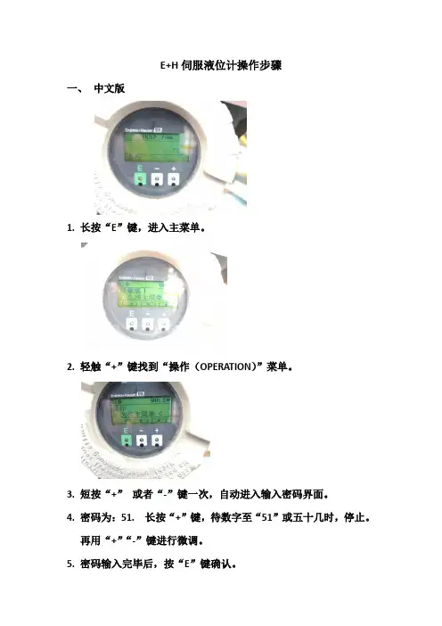
E+H伺服液位计操作步骤
一、中文版
1.长按“E”键,进入主菜单。
2.轻触“+”键找到“操作(OPERATION)”菜单。
3.短按“+”或者“-”键一次,自动进入输入密码界面。
4.密码为:51. 长按“+”键,待数字至“51”或五十几时,停止。
再用“+”“-”键进行微调。
5.密码输入完毕后,按“E”键确认。
6.收伺服时,在子菜单内短按“+”或者“-”选择“上升”,短按
“E”键等待即可,伺服上升至最高点时会自动停止;放伺服时,选择“液位”,短按“E”键等待即可,伺服至液位会自动停止。
备注:1.收起伺服时,若上升时卡住,无法继续上升时,下
降一段距离,再上升。
强行上升时,有可能将伺服液位计的
钢丝扯断。
2.放下伺服时,一般要求罐内液位至少为1.5M,少于1.5M
时,进料状态下罐内液位波动幅度较大,有可能使钢丝绳与
齿轮脱开,严重时可能将伺服液位计的钢丝扯断。
3.收起伺服液位计后,在表头下方的视窗内可以看到浮球。
一定要确认在视窗内看到浮球后,方可离去。
e+h超声波液位计说明书

e+h超声波液位计说明书E+H超声波液位计是一种用于测量液体或固体物料的非接触液位测量仪器。
它利用了超声波的传播特性来实现测量,并具有高精度、可靠性和适用性广的特点。
下面是该液位计的相关参考内容。
1. 原理及工作方式:E+H超声波液位计采用了时间差法原理进行测量。
它通过发射超声波脉冲并接收被液位反射的脉冲,根据传播时间差来计算出液位高度。
超声波的传播速度在大部分情况下是恒定的,因此,通过测量时间差可以准确计算出液位高度。
2. 设备特点和优势:- E+H超声波液位计可以适用于各种液体和固体物料的测量,包括有蒸汽、气体、油类、化学药品、腐蚀性物质等。
- 该液位计设备精度高,能够实现毫米级别的测量准确度。
- 它具有非接触式测量的特点,无需浸入液体或物料,不会对被测介质产生污染。
- 该液位计设备体积小巧,结构简单,并且安装操作方便。
- 它具有可靠性高的特点,适合于在严苛的工业环境中进行长时间运行。
3. 使用范围:E+H超声波液位计广泛应用于各种工业过程中的液位测量和控制,包括但不限于以下领域:- 石油、化工和制药行业中的储罐、反应器或混合槽等的液位监测。
- 发电厂中的锅炉水位和储罐液位的监测。
- 食品和饮料生产线中的液体测量和控制。
- 供水和污水处理系统中的液位监测。
- 液化气体储存罐的液位测量。
4. 安装及操作指南:- 在安装前,需要确定好液位计的安装位置,避免与其它设备或材料的干扰。
- 安装时,确保液位计与被测物料之间没有遮挡物,以确保测量的准确性。
- 液位计的操作需要按照说明书进行,加电和设置参数前,需要确保供电正常,并参考说明书设置相应的参数。
- 更换传感器或维护时,需要确保设备断电,并按照说明书进行操作。
总结:通过以上有关E+H超声波液位计的相关参考内容,我们了解到它的原理、工作方式、设备特点和优势,以及使用范围和安装操作指南。
这些信息为用户提供了使用和维护液位计的指导,同时也展示了该液位计的高精度和可靠性,满足了用户对液位测量的需求。
E+H料位计

为了简化功 能菜 单的浏览,在显示器上显 示有每个功能的位置 码。可以在功能 菜 单 索 引 ( 见83页) 中通 过 参 考 页 面/链接 访问 每 个 功 能, 所有 的 功 能 名 都 按 字 母和数字顺 序排 列。
5
1.4 操作菜单的结构
操作菜单由 两级 构成: ■ 功 能 组 (0 0、01、 …、0C、0D) :
50
2 4 8. 6 功 能 "设置 总线 单 位" ( 062) ,只 用于PRO F IBU S P A 5 0
2 6 8. 7 功 能 "电流 输出 模 式" ( 063 ), 只用 于H ART
51
2 6 8. 8 功 能 "输出 值" (0 63),只用 于P R OFI BU S PA
51
1.4 .1 功能识别
为 了 简 化 功 能菜 单的 操作 (见 第1 1页 ), 在显 示器 上显 示 每 个 功能 的位 置 。
功能组
功能
前两个数字 指示 其功能组:
■基本设置
00
■安全设定
01
■长度调整ຫໍສະໝຸດ 02…第三个数字 指示 功能组的各功能:
■基本设置
00→ ■储罐特性 00 2
■介质属性 003
5 "长 度 调 整"(03)功能组
5. 1 功 能 "探 头 末端" ( 030) 5. 2 功 能 "探 头 长度"( 031) 5. 3 功 能 "探 头"(0 32) 5. 4 功 能 "探 头 长度" ( 033) 5. 5 功 能 "确 定 长度" ( 034)
E+H雷达液位计
法兰: 测量参考点
.
故障现象 若液面不平静,例如:加注、 放空、搅拌)、测量值偶尔会 跳到最高值
故障原因 信号被不平静的液 面消弱了—干扰回波较强
修复方法 1.做干扰抑制图→基本标定 2.将过程条件process cond(004) 设置为“不平静表面 turb.surface” 或 “搅拌器agitator” 3.增加输出阻尼 (058) 4.优化方向(见第74页) 5.若有必要,选择更好的安装 位置和/或更大的天线
.
基本设定
罐体形状 拱顶罐
测量条件 未知
测量条件 标准
空罐标定
满罐标定
管直径 (用于旁通管/导波管)
固定目标抑制
雷达液位计基本设定
E:空罐标定 (=零点) 在005中设定 F:满罐标定 (=量程) 在006中设定 D:距离(法
兰与介质的距 离)
在0 中显示 L:液位在0 中 显示
SD:安全距离 在015中设定
.
雷达液位计输入输出工作原理
• 输出: • Micropilot 通过输入空罐E、满罐高度F及一些应用参数来
进行设定。应用参数将自动使仪表适应过程环境。对电流 输出型仪表,数据点“E”和“F”分别对应于4mA和20mA 输出,对数字输出型和显示模块,则分别对应于0% 和 100%。 • 可在现场或远程手工或半自动地通过输入表格(最多点) 进行线性化,以便对球罐、卧罐及锥底罐中的物位进行测 量。
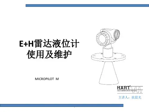
E+H雷达液位计 使用及维护
MICROPILOT M
.
主讲人:侯晨光
E+H雷达物位计简介及测量原理
MICROPILOT M FMR230是一种一体化的雷达物位变送器, 用于液体浆料及污泥的连续非接触测量该设备可安装在密 闭的金属容器外,这是因为其操作频率为约6GHZ,而其最 大辐射脉冲能量为(平均功率输出1μ W)该设备对人体及 动物完全无害。 Micropilot M是一种“俯视式”时间行程测量系统。用于测 量从参考点(即过程连接)到物料表面的间距。天线发出 微波脉冲,在被测物料表面产生反射,并被雷达系统所接 收。
E+H电容物位计

E+H电容物位计什么是E+H电容物位计E+H电容物位计是一种非接触式的液位或固体物位测量仪器。
这种仪器通常使用电容原理来测量物料的水平或垂直位置。
该仪器由艾默生和霍尼韦尔两家企业共同开发,并在全球范围内提供销售和支持服务。
E+H电容物位计的优点1.非接触式测量:E+H电容物位计能够进行非接触式测量,不会直接接触到物料,避免因接触而引起的杂音或损坏,增加了使用寿命。
2.高度可靠性:E+H电容物位计是一种非常可靠的液位或固体物位测量仪器。
它们被广泛应用于石化、化工、食品、饮料、水处理等行业。
3.稳定性强:这种仪器在测量过程中,受到大气压力、温度、水压等因素的影响很小,稳定性强,可以保证高精度的测量结果。
4.容易安装:E+H电容物位计安装简单,仅需进行简单的配管即可。
通常情况下,它们可以快速安装并立即投入使用。
5.低维护成本:E+H电容物位计具有长寿命和高可靠性,使用寿命长,维护成本低。
E+H电容物位计的应用E+H电容物位计被广泛应用于石化、化工、食品、饮料、水处理等行业。
下面将简单介绍它在这些行业中的主要应用:石化作为一种非接触式的测量仪器,E+H电容物位计在石化行业中被广泛应用于存储罐中的液位测量。
这可以确保石化生产过程中的安全性。
化工在化工行业中,E+H电容物位计通常用于测量各种液体、固体和粉末的物位。
这种测量装置能够快速、准确地测量物位,并使生产过程更加便捷。
食品和饮料在食品和饮料工业中,E+H电容物位计通常用于控制罐中的液位。
它们可以确保生产规格的一致性,并确保生产设备不会在过程中停机或崩溃。
水处理在水处理行业中,E+H电容物位计通常用于水池中水的液位测量,以便控制和监督水的使用和利用。
总结E+H电容物位计是一种高精度、高可靠性的液位或固体物位测量仪器,使用非接触式测量原理,被广泛应用于石化、化工、食品、饮料、水处理等行业中。
它们是一个方便的测量工具,不仅可以提高生产效率,而且可以在生产过程中降低维护成本。
e+h射频导纳料位开关中文说明书

e+h射频导纳料位开关:让物料的控制更加精准在工业生产中,物料的控制是非常重要的一环节。
而e+h射频导纳料位开关的出现,让这一环节变得更加精准。
e+h射频导纳料位开关的中文说明书详细介绍了它的工作原理、特点以及应用场景。
本文将以此为中心,进一步阐述e+h射频导纳料位开关的优势以及未来的发展趋势。
e+h射频导纳料位开关的工作原理e+h射频导纳料位开关是一种非接触式的物料控制设备。
它利用微波信号来检测物料的存在与否,从而实现对物料的控制。
e+h射频导纳料位开关的工作原理可以简单地概括为:当微波信号遇到物料时,部分信号会被反射回来,这些反射信号会被e+h射频导纳料位开关接收并处理。
通过处理后,e+h射频导纳料位开关可以判断物料的存在与否,从而实现对物料的控制。
e+h射频导纳料位开关的特点e+h射频导纳料位开关具有以下特点:1.非接触式控制:e+h射频导纳料位开关不需要与物料接触,从而避免了物料对设备的损坏以及污染。
2.精准控制:e+h射频导纳料位开关可以对物料进行精准的控制,从而提高了生产效率。
3.安全可靠:e+h射频导纳料位开关采用微波信号进行控制,不会对人体造成伤害,同时也可以避免因接触式控制而引起的安全隐患。
4.高度可定制化:e+h射频导纳料位开关可以根据不同的应用场景进行定制化设计,从而满足不同的需求。
e+h射频导纳料位开关的应用场景e+h射频导纳料位开关在工业生产中有着广泛的应用场景。
例如,在化工、食品、医药等行业中,e+h射频导纳料位开关可以用于对液体、粉末、颗粒等物料的控制。
在石油、天然气等行业中,e+h射频导纳料位开关也可以用于对油气的控制。
e+h射频导纳料位开关在各个行业中都有着广泛的应用。
未来的发展趋势随着工业生产的不断发展,e+h射频导纳料位开关也在不断地发展和改进。
未来,e+h射频导纳料位开关将会有以下发展趋势:1.智能化:e+h射频导纳料位开关将会越来越智能化,可以通过互联网进行远程控制和监测。
vega料位计说明书
vega料位计说明书一、设备简介VEGA料位计是一种精确测量固体料位高度的仪器。
它广泛应用于各种工业环境,如化工、食品、制药等,用于监测和控制在料仓、输送带或其他容器中的物料高度。
VEGA料位计以其高效、可靠和精确的性能,为用户提供了方便快捷的测量方式。
二、工作原理VEGA料位计基于回声测量原理工作,通过向物料表面发出超声波信号,并测量反射回来的信号时间,计算出料位的高度。
由于超声波在空气中的传播速度几乎不受温度、压力等环境因素的影响,因此VEGA料位计具有很高的测量精度和稳定性。
三、安装步骤1. 确定安装位置:选择一个能反映物料真实高度的位置,避开进料口、出料口及物料堆积处。
2. 安装固定:使用适当的紧固件将VEGA料位计固定在选定的位置。
3. 连接电缆:将VEGA料位计的电缆连接到相应的电源和数据采集设备上。
4. 调试校准:根据使用的物料特性和环境条件,对VEGA料位计进行校准和调试。
四、操作说明1. 启动设备:接通电源,打开电源开关,设备开始工作。
2. 数据读取:通过连接的数据采集设备,可以实时读取和记录料位的高度数据。
3. 异常处理:当设备出现异常或测量误差较大时,应及时检查设备的工作状态和校准情况。
五、维护与保养1. 定期清洁:定期清洁超声波传感器表面,保持清洁无杂物,以防止对测量结果产生影响。
2. 校准检查:定期对VEGA料位计进行校准,以确保测量的准确性。
3. 更换电池:当电池电量低时,应及时更换电池,以保证设备的正常运行。
六、常见问题及解决方案1. 测量不准确:可能是由于传感器表面污染或物料特性影响,需要清洁传感器表面或检查物料特性。
2. 无数据显示:可能是电源故障或数据采集设备连接问题,应检查电源和连接线路。
七、技术参数1. 测量范围:根据不同型号和规格,测量范围在几米至几十米不等。
2. 精度:±1% 或更高。
3. 工作温度:一般可在-20℃至+60℃之间工作。
4. 电源:DC12V 或AC24V,具体视型号而定。
E+H伺服液位计培训教材PPT精选文档
Slide 16
01/14/2011 Slide 17
带导波管安装
导波管直径要求 导波管能保护测 量钢丝,但不影 响其测量,导波 管直径视管高而 定,可以上下相 同,也可以上小 下大。
注:应用于带压 罐上时必须使用 阀门。
注:安装于不对称 导波管,罐顶上时 必须必须依据图示 安装
(Calendar)
ALARM CONTACT
(Alarm Message)
DIAGNOSTIC (Erroneous
CO
Message)
ACCESS CODE
01/14/2011 Slide 29
操作 矩阵设置
静态矩阵参数设置( Static Matrix G0 Settings)
上层介质密度( Upper Density 005 )
01/14/2011 Slide 24
当防爆认证是EEx d(ia),与其它本安HART仪表(如NMT539)连 接时,只允许使用电缆入口C 。
请核实伺服液位计的型号是否带Pt100输入功能?错误的连接设
备到24、25和26接线端子,将会造成不可修复的硬件损坏!!!
01/14/2011 Slide 25
Level
Displacer
01/14/2011 Slide 13
工作原理
液位变化-Liquid surface change “浮子重量”变化-Displacer Buoyancy change : Displacer
weight change 轮毂转动Drum rotation: Shift of magnetic position 磁通量变化Hall elements detect magnetic flux change 重量信号变化-Weight signal changed 计算重量值-CPU calculates displacer weight value 驱动马达找到新液面-CPU controls motor to balance displacer
德国E+H电磁流量计的原理及安装准备
德国E+H电磁流量计的原理及安装准备德国E+H电磁流量计的口径范围比其他品种流量仪表宽,E+H公司提供W、P、H 三种类型的传感器,分别应用于水和污水行业(W型),化工、食品行业(P型),食品、制药行业(H型),口径范围从2毫米到2米。
变送器可提供10、50、23、53多种选择,10针对于水行业开发的经济型,50为普通型,53为增强型,23为两线制。
精度可有0.5%,0.2%两种选择。
可测正反双向流量,也可测脉动流量。
使用E+H电磁流量计的前提是被测液体必须是导电的,不能低于阈值(即下限值)。
电导率低于阈值会产生测量误差直至不能使用,超过阈值即使变化也可以测量,示值误差变化不大,通用型电磁流量计的阈值在10-4~(5×10⁻⁶)S/cm之间,视型号而异。
使用时还取决于传感器和转换器间流量信号线长度及其分布电容,制造厂使用说明书中通常规定电导率相对应的信号线长度。
工业用水及其水溶液的电导率大于10-4S/cm,酸、碱、盐液的电导率在10-4~10-1S/cm之间,使用不存在问题,低度蒸馏水为10-5S/cm也不存在问题。
电磁流量计不能测量电导率很低的液体,如石油制品和有机溶剂等。
不能测量气体、蒸汽和含有较多较大气泡的液体。
从资料上查到有些纯液或水溶液电导率较低,认为不能使用,然而实际工作中会遇到因含有杂质而能使用的实例,这类杂质对增加电导率有利。
对于水溶液,资料中的电导率是用纯水配比在实验室测得的,实际使用的水溶液可能用工业用水配比,电导率将比查得的要高,也有利于流量测量。
E+H电磁流量计由流量传感器和变送器两大部分组成。
传感器测量管上下装有励磁线圈,通励磁电流后产生磁场穿过测量管,一对电极装在测量管内壁与液体相接触,引出感应电势,送到变送器。
励磁电流则由变送器提供。
按转换器与传感器组装方式分类,有分离型和一体型两种。
在污水处理工艺中大口径流量计多为分体式,一部分安装在地下,另一部分在地上。
E+H料位计说明书
TI418F/24/ae/04.10Technical InformationSolicap M FTI55, FTI56CapacitancePoint level switch for bulk solidsApplicationSolicap M is used for point level detection in bulk solids and can be operated in minimum or maximum fail-safe mode.Due to its robust construction, it can also be used to provide accurate measurements in applications with very high tensile loads (up to 60 kN / 13,500 lbf for cable version) or lateral loads (up to 300 Nm / 220 lbf ft for rod version).In combination with Fieldgate (for remote interrogation of measured values using internet technology), Solicap M represents an ideal solution for material provisioning and logistical optimization (inventory control).Your benefits•Extremely robust design for harsh process conditions •Easy and fast commissioning as calibration is performed at the press of a button•Universal application thanks to wide range of certificates and approvals•Two-stage overvoltage protection against static discharges from the silo•Active buildup compensation for bulk solids that tend to cake•Use in safety systems with specific requirements in terms of functional safety to SIL2/SIL3 in conjunction with electronic insert FEI55•Increased safety due to permanent automatic monitoring of electronics•Reduction in storage costs thanks to easy-to-shorten rod model (for partial insulation) and cable model (for partial and full insulation)•Two-point control (e.g. for controlling a handling device)Solicap M FTI55, FTI562Endress+HauserTable of contentsFunction and system design. . . . . . . . . . . . . . . . . . . . .4Measuring principle . . . . . . . . . . . . . . . . . . . . . . . . . . . . . . . . . . . 4Application examples . . . . . . . . . . . . . . . . . . . . . . . . . . . . . . . . . . 4Measuring system . . . . . . . . . . . . . . . . . . . . . . . . . . . . . . . . . . . . . 5Electronic versions . . . . . . . . . . . . . . . . . . . . . . . . . . . . . . . . . . . . 7System integration via Fieldgate . . . . . . . . . . . . . . . . . . . . . . . . . . 8Operating conditions: Installation . . . . . . . . . . . . . . . .9General notes . . . . . . . . . . . . . . . . . . . . . . . . . . . . . . . . . . . . . . . . 9Preparing to install rod probes FTI55 . . . . . . . . . . . . . . . . . . . . . 10Preparing to install cable probes FTI56 . . . . . . . . . . . . . . . . . . . . 12Probe with separate housing . . . . . . . . . . . . . . . . . . . . . . . . . . . . 16Operating conditions: Environment. . . . . . . . . . . . . .18Ambient temperature range . . . . . . . . . . . . . . . . . . . . . . . . . . . . 18Storage temperature . . . . . . . . . . . . . . . . . . . . . . . . . . . . . . . . . . 18Climate class . . . . . . . . . . . . . . . . . . . . . . . . . . . . . . . . . . . . . . . 18Degree of protection . . . . . . . . . . . . . . . . . . . . . . . . . . . . . . . . . . 18Vibration resistance . . . . . . . . . . . . . . . . . . . . . . . . . . . . . . . . . . 18Cleaning . . . . . . . . . . . . . . . . . . . . . . . . . . . . . . . . . . . . . . . . . . 18Electromagnetic compatibility (EMC) . . . . . . . . . . . . . . . . . . . . . 18Shock resistance . . . . . . . . . . . . . . . . . . . . . . . . . . . . . . . . . . . . 18Operating conditions: Process. . . . . . . . . . . . . . . . . .19Process temperature range . . . . . . . . . . . . . . . . . . . . . . . . . . . . . 19Process pressure and temperature derating . . . . . . . . . . . . . . . . . 21State of aggregation. . . . . . . . . . . . . . . . . . . . . . . . . . . . . . . . . . 22Mechanical construction . . . . . . . . . . . . . . . . . . . . . .23Overview . . . . . . . . . . . . . . . . . . . . . . . . . . . . . . . . . . . . . . . . . . 23Material . . . . . . . . . . . . . . . . . . . . . . . . . . . . . . . . . . . . . . . . . . . 28Weight . . . . . . . . . . . . . . . . . . . . . . . . . . . . . . . . . . . . . . . . . . . . 28Input . . . . . . . . . . . . . . . . . . . . . . . . . . . . . . . . . . . . .29Measured variable . . . . . . . . . . . . . . . . . . . . . . . . . . . . . . . . . . . 29Measuring range (valid for all FEI5x) . . . . . . . . . . . . . . . . . . . . . 29Input signal . . . . . . . . . . . . . . . . . . . . . . . . . . . . . . . . . . . . . . . . 29Measuring conditions . . . . . . . . . . . . . . . . . . . . . . . . . . . . . . . . . 29Output. . . . . . . . . . . . . . . . . . . . . . . . . . . . . . . . . . . .30Galvanic isolation . . . . . . . . . . . . . . . . . . . . . . . . . . . . . . . . . . . . 30Switch behavior . . . . . . . . . . . . . . . . . . . . . . . . . . . . . . . . . . . . . 30Switch-on behavior . . . . . . . . . . . . . . . . . . . . . . . . . . . . . . . . . . 30Fail-safe mode . . . . . . . . . . . . . . . . . . . . . . . . . . . . . . . . . . . . . . 30Switching delay . . . . . . . . . . . . . . . . . . . . . . . . . . . . . . . . . . . . . 30Electronic insert FEI51 (AC 2-wire) . . . . . . . . . . . . .31Power supply . . . . . . . . . . . . . . . . . . . . . . . . . . . . . . . . . . . . . . . 31Electrical connection . . . . . . . . . . . . . . . . . . . . . . . . . . . . . . . . . 31Signal on alarm . . . . . . . . . . . . . . . . . . . . . . . . . . . . . . . . . . . . . 31Output signal . . . . . . . . . . . . . . . . . . . . . . . . . . . . . . . . . . . . . . . 31Connectable load . . . . . . . . . . . . . . . . . . . . . . . . . . . . . . . . . . . . 31FEI52 electronic insert (DC PNP) . . . . . . . . . . . . . . .32Power supply . . . . . . . . . . . . . . . . . . . . . . . . . . . . . . . . . . . . . . . 32Electrical connection . . . . . . . . . . . . . . . . . . . . . . . . . . . . . . . . . 32Output signal . . . . . . . . . . . . . . . . . . . . . . . . . . . . . . . . . . . . . . . 32Signal on alarm . . . . . . . . . . . . . . . . . . . . . . . . . . . . . . . . . . . . . 32Connectable load . . . . . . . . . . . . . . . . . . . . . . . . . . . . . . . . . . . . 32Electronic insert FEI53 (3-wire) . . . . . . . . . . . . . . . .33Power supply . . . . . . . . . . . . . . . . . . . . . . . . . . . . . . . . . . . . . . . 33Electrical connection . . . . . . . . . . . . . . . . . . . . . . . . . . . . . . . . . 33Output signal . . . . . . . . . . . . . . . . . . . . . . . . . . . . . . . . . . . . . . 33Signal on alarm . . . . . . . . . . . . . . . . . . . . . . . . . . . . . . . . . . . . . 33Connectable load . . . . . . . . . . . . . . . . . . . . . . . . . . . . . . . . . . . . 33FEI54 electronic insert (AC/DC with relay output) .34Power supply . . . . . . . . . . . . . . . . . . . . . . . . . . . . . . . . . . . . . . . 34Electrical connection . . . . . . . . . . . . . . . . . . . . . . . . . . . . . . . . . 34Output signal . . . . . . . . . . . . . . . . . . . . . . . . . . . . . . . . . . . . . . . 34Signal on alarm . . . . . . . . . . . . . . . . . . . . . . . . . . . . . . . . . . . . . 34Connectable load . . . . . . . . . . . . . . . . . . . . . . . . . . . . . . . . . . . . 34Electronic insert FEI55 (8/16 mA; SIL2/SIL3) . . . . .35Power supply . . . . . . . . . . . . . . . . . . . . . . . . . . . . . . . . . . . . . . . 35Electrical connection . . . . . . . . . . . . . . . . . . . . . . . . . . . . . . . . . 35Output signal . . . . . . . . . . . . . . . . . . . . . . . . . . . . . . . . . . . . . . . 35Signal on alarm . . . . . . . . . . . . . . . . . . . . . . . . . . . . . . . . . . . . . 35Connectable load . . . . . . . . . . . . . . . . . . . . . . . . . . . . . . . . . . . . 35FEI57S electronic insert (PFM) . . . . . . . . . . . . . . . . .36Power supply . . . . . . . . . . . . . . . . . . . . . . . . . . . . . . . . . . . . . . . 36Electrical connection . . . . . . . . . . . . . . . . . . . . . . . . . . . . . . . . . 36Output signal . . . . . . . . . . . . . . . . . . . . . . . . . . . . . . . . . . . . . . . 36Signal on alarm . . . . . . . . . . . . . . . . . . . . . . . . . . . . . . . . . . . . . 36Connectable load . . . . . . . . . . . . . . . . . . . . . . . . . . . . . . . . . . . . 36Electronic insert FEI58 (NAMUR H-L edge) . . . . . . .37Power supply . . . . . . . . . . . . . . . . . . . . . . . . . . . . . . . . . . . . . . . 37Electrical connection . . . . . . . . . . . . . . . . . . . . . . . . . . . . . . . . . 37Output signal . . . . . . . . . . . . . . . . . . . . . . . . . . . . . . . . . . . . . . . 37Signal on alarm . . . . . . . . . . . . . . . . . . . . . . . . . . . . . . . . . . . . . 37Connectable load . . . . . . . . . . . . . . . . . . . . . . . . . . . . . . . . . . . . 37Power supply. . . . . . . . . . . . . . . . . . . . . . . . . . . . . . .38Electrical connection . . . . . . . . . . . . . . . . . . . . . . . . . . . . . . . . . 38Connector . . . . . . . . . . . . . . . . . . . . . . . . . . . . . . . . . . . . . . . . . 38Cable entry . . . . . . . . . . . . . . . . . . . . . . . . . . . . . . . . . . . . . . . . 38Performance characteristics. . . . . . . . . . . . . . . . . . . .39Reference operating conditions . . . . . . . . . . . . . . . . . . . . . . . . . . 39Switch point . . . . . . . . . . . . . . . . . . . . . . . . . . . . . . . . . . . . . . . 39Ambient temperature effect . . . . . . . . . . . . . . . . . . . . . . . . . . . . 39Human interface . . . . . . . . . . . . . . . . . . . . . . . . . . . .40Electronic inserts . . . . . . . . . . . . . . . . . . . . . . . . . . . . . . . . . . . . 40Electronic inserts . . . . . . . . . . . . . . . . . . . . . . . . . . . . . . . . . . . . 41Electronic insert . . . . . . . . . . . . . . . . . . . . . . . . . . . . . . . . . . . . . 42Solicap M FTI55, FTI56 Certificates and approvals. . . . . . . . . . . . . . . . . . . . . 43CE approval . . . . . . . . . . . . . . . . . . . . . . . . . . . . . . . . . . . . . . . . 43Additional certification . . . . . . . . . . . . . . . . . . . . . . . . . . . . . . . 43Other standards and guidelines . . . . . . . . . . . . . . . . . . . . . . . . . 43Ordering information . . . . . . . . . . . . . . . . . . . . . . . . 44Solicap M FTI55 . . . . . . . . . . . . . . . . . . . . . . . . . . . . . . . . . . . . 44Solicap M FTI56 . . . . . . . . . . . . . . . . . . . . . . . . . . . . . . . . . . . . 46Accessories . . . . . . . . . . . . . . . . . . . . . . . . . . . . . . . . 47Weather protection cover . . . . . . . . . . . . . . . . . . . . . . . . . . . . . . 47Overvoltage protection HAW56x . . . . . . . . . . . . . . . . . . . . . . . . 47Spare parts . . . . . . . . . . . . . . . . . . . . . . . . . . . . . . . . . . . . . . . . . 47Documentation . . . . . . . . . . . . . . . . . . . . . . . . . . . . . 48Technical Information . . . . . . . . . . . . . . . . . . . . . . . . . . . . . . . . 48Operating Instructions . . . . . . . . . . . . . . . . . . . . . . . . . . . . . . . . 48Certificates . . . . . . . . . . . . . . . . . . . . . . . . . . . . . . . . . . . . . . . . 48Patents . . . . . . . . . . . . . . . . . . . . . . . . . . . . . . . . . . . . . . . . . . . 483Endress+HauserSolicap M FTI55, FTI56Function and system designMeasuring principle The principle of capacitance point level detection is based on the change in capacitance of a capacitor as a resultof the probe being covered by bulk solids. The probe and container wall (conductive material) form an electriccapacitor. When the probe is in air (1), a certain low initial capacitance is measured. If the container is beingfilled, the capacitance of the capacitor increases as more of the probe is covered (2), (3).The point level switch switches when the capacitance C S specified during calibration is reached.In addition, a probe with inactive length ensures that the effects of medium buildup or condensate near theprocess connection are avoided. A probe with active buildup compensation compensates for the effects ofbuildup on the probe in the area of the process connection.R: Conductivity of bulk solidsC: Capacitance of bulk solidsC A: Initial capacitance (probe not covered)C S: Switching capacitance∆C: Change in capacitanceFunctionThe electronic insert selected for the probe determines the change in capacitance depending on how much ofthe probe is covered. This ensures accurate switching at the switchpoint (level) calibrated for this purpose. Application examples Sand, glass aggregate, gravel, molding sand, lime, ore (crushed), plaster, aluminum shavings, cement, grain,pumice, flour, dolomite, sugar beet, kaolin, fodder and similar bulk solids.In general:Bulk solids with a relative dielectric constant εr≥ 2.5.4Endress+HauserSolicap M FTI55, FTI56Endress+Hauser 5Measuring system The make-up of the measuring system depends on the electronic insert selected.Point level switchThe complete measuring system consists of: •the point level switch, Solicap M FTI55 or FTI56•An electronic insert FEI51, FEI52, FEI54Two-point control ( s function)!Note!Partially insulated probes only in conjunction with nonconductive bulk solids.Solicap M FTI55, FTI56The point level switch can also be used to control a screw conveyor, for example, where the on and off valuescan be freely defined.Point level switchSolicap M FTI5x with electronic versions FEI53, FEI57S and FEI58 for connecting to a separate switching unit.The complete measuring system consists of:•the capacitance point level switch, Solicap M FTI55 or FTI56•an electronic insert FEI53, FEI57S, FEI58•a transmitter power supply unit e.g. FTC325, FTC625 (SW V1.4 or higher), FTC470Z, FTC471Z, FTL325N,FTL375N* Only possible with FEI53The following table shows the transmitter power supply units available which can be operated with electronicinserts FEI57S and FEI53.Electronic insert FEI57S FEI53FEI58Transmitter power supply unitFTC625x––FTC325x x–FTL325N––xFTL375N––xFTC470Z x––FTC471Z x––FTC520Z*x––FTC521Z*x––FTC420*–x–FTC421*–x–FTC422*–x–x Combination is possible– Combination is not possible* Product phase-out 20066Endress+HauserSolicap M FTI55, FTI56Point level switch 8/16 mAThe complete measuring system consists of:•the point level switch, Solicap M FTI55 or FTI56•the FEI55 electronic insert•a transmitter power supply unit (e.g. RN221N, RNS221, RMA421, RMA422)Electronic versions FEI51Two-wire AC connection•Load switched directly into the power supply circuit via the thyristor.•Point level adjustment directly at the point level switch.FEI523-wire direct current version:•Switch the load via the transistor (PNP) and separate supply voltage connection.•Point level adjustment directly at the point level switch.FEI533-wire direct current version with 3 to 12 V signal output:•For separate switching unit, Nivotester FTC325 3–WIRE.•Point level adjustment directly at the switching unit.FEI54Universal current version with relay output:•Switch the loads via 2 floating changeover contacts (DPDT).•Point level adjustment directly at the point level switch.FEI55Signal transmission 8/16 mA on two-wire cabling:•SIL2 approval for the hardware•SIL3 approval for the software•For separate switching unit (e.g. RN221N, RNS221, RMA421, RMA422).•Point level adjustment directly at the point level switch.FEI57SPFM signal transmission (current pulses are superimposed on the supply current):•For separate switching unit with PFM signal transmission e.g. FTC325 PFM, FTC625 PFM andFTC470Z/471ZEndress+Hauser7Solicap M FTI55, FTI568Endress+Hauser•Self-test from the switching unit without changing levels.•Point level adjustment directly at the point level switch.•Cyclical checking from the switching unit.FEI58 (NAMUR)Signal transmission H-L edge 2.2 to 3.5 / 0.6 to 1.0 mA as per IEC 60947-5-6 on two-wire cable:•For a separate switching unit (e.g. Nivotester FTL325N and FTL375N).•Point level adjustment directly at the point level switch.•Test the connection cables and slaves by pressing the button on the electronic insert.!Note!For additional information see 31 ff.System integration via FieldgateVendor managed inventoryThe remote interrogation of tank or silo levels via Fieldgate enables suppliers of raw materials to gatherinformation about the current inventories of their regular customers at any time and, for example, to take this into account in their own production planning. The Fieldgate monitors the configured point levels and automatically triggers the next order as required. Here, the range of possibilities ranges from simple requisitioning by e-mail through to fully automatic order processing by incorporating XML data into the planning systems on both sides.Remote maintenance of measuring systemsNot only does Fieldgate transmit the current measured values, it also alerts the standby personnel responsible by e-mail or SMS as required. Fieldgate forwards the information transparently. In this way, all options of the operating software in question are available remotely. By using remote diagnosis and remote configuration some onsite service operations can be avoided and all others can at least be planned and prepared better.Solicap M FTI55, FTI56Endress+Hauser 9Operating conditions: Installation!Note!All dimensions in inches (mm).General notesFilling the siloThe filling stream should not be directed onto the probe.Angle of material flowNote the expected angle of the material flow or of the outlet funnel when determining the mounting location or probe length.Distance between probesWhen installing several probes in a silo, a minimum distance of 20" (0.5m) between the probes must be observed.Threaded coupling for mountingWhen installing the Solicap M FTI55, FTI56, the threaded coupling should be as short as possible.Condensation or product residue may occur in a long threaded coupling and interfere with the correct operation of the probe.Heat insulationIn the event of high temperatures in the silo:Insulate the external silo wall to avoid exceeding the permitted temperature of the Solicap M housing.Heat insulation also prevents condensation from forming near the threaded boss in the silo. This reduces buildup and the risk of error switching.Solicap M FTI55, FTI5610Endress+HauserPreparing to install rod probes FTI55Correct installationa.For maximum point level detection, a short threaded coupling is used.b.For minimum point level detection, a short threaded coupling is used.c.In the event of light buildup on the silo wall, the threaded coupling is welded internally.The probe tip points slightly downwards so that bulk solids slide off more easily.Incorrect installationd.The threaded coupling is too long. This may cause material to settle inside and result in error switching.e.Horizontal mounting means a risk of error switching in the event of heavy buildup on the silo wall.In this case, the Solicap M FTI55 (rod probe) with inactive length is recommended.f.In areas where product buildup occurs, the device cannot detect if the silo is "empty". In this case, the FTI56 (cable probe) should be installed from above.Correct installationIncorrect installationProbe length and minimum coverage!Note!•When selecting the probe length, pay attention to the dependency between the relative dielectric constant εr and the minimum amount the probe rod needs to be covered (see Table). •For probe length tolerances see →26.•To ensure problem-free operation, it is important that the difference in capacitance between the covered and uncovered parts of the probe is at least 5 pF.•If you do not know the dielectric constant of the material, contact us for advice.In this example, the grounded steel plate forms the counter electrode.Heat insulation prevents condensation and therefore buildup on the steel plate.In a silo with concrete wallsWhen installing in a silo made of plastic, a sheet metal plate must be attached to the exterior of the silo as a counter electrode.This plate can be either square or round.–Dimensions in the case of a thin silo wall with a low dielectric constant:approx. 0.5 m along each side or ø0.5 m; –Dimensions in the case of a thicker silo wall or wall with a higher dielectric constant:approx. 0.7 m along each side or ø0.7 m.In a silo with plastic wallsPreparing to install cable probes FTI56Correct installationa.Solicap M FTI55, FTI56 with inactive length in the event of condensation and material buildup on the silo roof.b.At the correct distance from the silo wall, the material inlet and the material outlet.Close to the wall, for reliable switching in the case of a low dielectric constant (not for pneumatic filling).For pneumatic filling, the distance from the probe to the wall should not be too short, as the probe may swing.Incorrect installationc.If too close to the material inlet, inflowing bulk solids may damage the sensor.If close to the center of the material outflow, high tensile forces at this point may cause the probe to break off or subject the silo roof to excessive strain.d.The threaded coupling is too long. This may cause condensation and dust to settle inside which may result in error switching.e.If too close to the silo wall, the probe may swing slightly against the wall or come in contact with buildup. This can result in error switching.Correct installation Incorrect installationIn a silo with metal wallsDistance D between the probe and the wall approx. 10 to 25 % of the silo diameterSilo roofEnsure that the silo roof is of a sufficiently stable construction.High tensile forces may occur when material is being extracted, particularly in the case of heavy and powdery bulk solids which have a tendency to form buildup.Coarse-grained bulk solidsIn silos with extremely coarse-grained or extremely abrasive bulk solids, the use of a Solicap M FTI55 or FTI56 is recommended only for maximum detection.Distance between the rope probesTo rule out mutual probe interference, you must maintain a minimum distance of 0.5 m (20") between the cable probes. This also applies if you are installing several Solicap M units in adjacent silos with nonconductive walls.In the event of condensation:Use the Solicap M with inactive length.The inactive length (A ) prevents moisture and buildup forming between the active part of the probe and the silo roof.Or:To reduce the effects of condensation (B ) and buildup, the threaded coupling (length: max. 25 mm / 1") must project into the silo.Heat insulation reduces condensation and therefore buildup on the steel plate.ASilo with walls that conduct electricity BSilo with concrete wallsInstallation in the event of buildupInstallation in plastic tanksIf buildup on the probe rod can be expected when operating the measuring system, the active buildup compensation function prevents the measurement result from becoming distorted. No cleaning work has to be performed on the probe rod.When installing in a silo made of plastic, a counter electrode must be mounted on the silo exterior at the same height as the tensioning weight.The length of the edge of the counter electrode should be approximately the same length as the distance between the tensioning weight and the silo wall.In a silo with plastic wallsRange of sensor lengthsShortening the probeRod probe:The partially insulated version can be shortened at a later stage by the user.Cable probe:Both versions (partially and fully insulated) may be shortened at a later stage.Electrically conductive bulk solids (e.g. coal)Bulk solids with high dielectric constant (e.g. rock salt)Bulk solids with low dielectric constant (e.g. dried grain)* L B (covered length):For nonconductive bulk solids with a low dielectric constant, the cable probe must be approx. 5 % (but no less than 250 mm / 10") longer than the distance between the tank roof and the required point level.Probe with separate housing!Note!•For information on how to order, see also "Ordering information" from Page 44 under "Probedesign".•The maximum connection length between the probe and the separate housing is 6 m (L4).When ordering a Solicap M with a separate housing, the desired length must be specified.•If the connecting cable is to be shortened or passed through a wall, it must be separated from theprocess connection. See also Page 16 (extension heights).•The cable has a bending radius of r 100 mm (4"). This must be observed as a minimum.Rod length L1 max. 4 m (13 ft)Rope length L1 max. 19.7 m / 64.6 ft (the maximum total length of L1 + L4 should not exceed 20 m / 65 ft.)Extension heightsHousing side: wall mounting Housing side: pipe mounting Sensor sidePolyester housing F16Stainless steel housing F15Aluminum housing F17B- 2.99" (76) 2.52" (64) 2.56" (65)H1- 6.77" (172) 6.54" (166) 6.97" (177)D 1.97" (50)---H4 2.44" (62)---!Note!•Connecting cable: ø10.5 mmn (0.41")•Outer jacket: silicone, notch-resistantWall holder unit!Note!•The wall holder unit is part of the scope of supply.•The wall holder unit has to be screwed to the separate housing before you can use it as a drilling template.The distance between the holes is reduced by screwing it to the separate housing.Temperature-derating separate housingaT P: process temperature* temperature at remote housing 70°C (158°F)!Note!The maximum connection length between the probe and the separate housing is 6 m / 20 ft (L4). Whenordering a device with a remote housing, the desired length must be specified.If the connecting cable is to be shortened or passed through a wall, it must be separated from the processconnection. See "Documentation" => "Operating Instructions" on Page 49.Operating conditions: EnvironmentAmbient temperature range•Ambient temperature of the transmitter (note derating, see Page 19): ❑–50 to +70°C (-58 to +158°F)❑–40 to +70°C (-40 to +158°F), with F16 housing•A weather protection cover should be used when operating outdoors in strong sunlight. For further information on the weather protection cover, see Page 48.Storage temperature –50 to +85°C (-58 to +185°F)Climate class DIN EN 60068-2-38/IEC 68-2-38: test Z/ADDegree of protection* As per EN60529** As per NEMA 250*** Only with M20 cable entry or G1/2 threadVibration resistanceDIN EN 60068-2-64/IEC 68-2-64: 20 Hz– 2000 Hz; 0.01 g 2/HzCleaning Housing :When cleaning, make sure that the cleaning agent used does not corrode the housing surface or the seals.Probe :Depending on the application, buildup (contamination and soiling) can form on the probe rod. A high degree of material buildup can affect the measurement result. If the medium tends to create a high degree of buildup, regular cleaning is recommended. When cleaning, it is important to make sure that the insulation of the probe rod is not damaged. If cleaning agents are used make sure the material is resistant to them!Electromagnetic compatibility (EMC)•Interference emission to EN 61326, Electrical Equipment Class BInterference immunity in accordance with EN 61326, Appendix A (Industrial) and NAMUR Recommendation NE 21(EMC)•A usual commercial instrument cable can be used.Shock resistanceDIN EN 60068-2-27/IEC 68-2-27: 30g accelerationIP66*IP67*IP68*NEMA4X**Polyester housing F16X X -X Stainless steel housing F15X X -X Aluminum housing F17X X -X Aluminum housing F13with gas-tight process seal X –X***X Aluminum housing T13with gas-tight process seal andseparate connection compartment (EEx d)X–X***XSeparate housingX –X***X。