直流电动机中英文对照外文翻译文献
电机行业常用的中英文对照
盛年不重来,一日难再晨。
及时宜自勉,岁月不待人。
电机行业常用的中英文对照induction machine 感应式电机horseshoe magnet 马蹄形磁铁magnetic field 磁场eddy current 涡流right-hand rule 右手定则left-hand rule 左手定则slip 转差率induction motor 感应电动机rotating magnetic field 旋转磁场winding 绕组stator 定子rotor 转子induced current 感生电流time-phase 时间相位exciting voltage 励磁电压slot 槽lamination 叠片laminated core 叠片铁芯short-circuiting ring 短路环squirrel cage 鼠笼rotor core 转子铁芯cast-aluminum rotor 铸铝转子bronze 青铜horsepower 马力random-wound 散绕insulation 绝缘ac motor 交流环电动机end ring 端环alloy 合金coil winding 线圈绕组form-wound 模绕performance characteristic 工作特性frequency 频率revolutions per minute 转/分motoring 电动机驱动generating 发电per-unit value 标么值breakdown torque 极限转矩breakaway force 起步阻力overhauling 检修wind-driven generator 风动发电机revolutions per second 转/秒number of poles 极数speed-torque curve 转速力矩特性曲线plugging 反向制动synchronous speed 同步转速percentage 百分数locked-rotor torque 锁定转子转矩full-load torque 满载转矩prime mover 原动机inrush current 涌流magnetizing reacance 磁化电抗line-to-neutral 线与中性点间的staor winding 定子绕组leakage reactance 漏磁电抗no-load 空载full load 满载Polyphase 多相(的)iron-loss 铁损complex impedance 复数阻抗rotor resistance 转子电阻leakage flux 漏磁通locked-rotor 锁定转子chopper circuit 斩波电路separately excited 他励的compounded 复励dc motor 直流电动机de machine 直流电机speed regulation 速度调节shunt 并励series 串励armature circuit 电枢电路optical fiber 光纤interoffice 局间的waveguide 波导波导管bandwidth 带宽light emitting diode 发光二极管silica 硅石二氧化硅regeneration 再生, 后反馈放大coaxial 共轴的,同轴的high-performance 高性能的carrier 载波mature 成熟的Single Side Band(SSB) 单边带coupling capacitor 结合电容propagate 传导传播modulator 调制器demodulator 解调器line trap 限波器shunt 分路器Amplitude Modulation(AM 调幅Frequency Shift Keying(FSK) 移频键控tuner 调谐器attenuate 衰减incident 入射的two-way configuration 二线制generator voltage 发电机电压dc generator 直流发电机polyphase rectifier 多相整流器boost 增压time constant 时间常数forward transfer function 正向传递函数error signal 误差信号regulator 调节器stabilizing transformer 稳定变压器time delay 延时direct axis transient time constant 直轴瞬变时间常数transient response 瞬态响应solid state 固体buck 补偿operational calculus 算符演算gain 增益pole 极点feedback signal 反馈信号dynamic response 动态响应voltage control system 电压控制系统mismatch 失配error detector 误差检测器excitation system 励磁系统field current 励磁电流transistor 晶体管high-gain 高增益boost-buck 升压去磁feedback system 反馈系统reactive power 无功功率feedback loop 反馈回路automatic Voltage regulator(A VR)自动电压调整器reference Voltage 基准电压magnetic amplifier 磁放大器amplidyne 微场扩流发电机self-exciting 自励的limiter 限幅器manual control 手动控制block diagram 方框图linear zone 线性区potential transformer 电压互感器stabilization network 稳定网络stabilizer 稳定器air-gap flux 气隙磁通saturation effect 饱和效应saturation curve 饱和曲线flux linkage 磁链per unit value 标么值shunt field 并励磁场magnetic circuit 磁路load-saturation curve 负载饱和曲线air-gap line 气隙磁化线polyphase rectifier 多相整流器circuit components 电路元件circuit parameters 电路参数electrical device 电气设备electric energy 电能primary cell 原生电池energy converter 电能转换器conductor 导体heating appliance 电热器direct-current 直流time invariant 时不变的self-inductor 自感mutual-inductor 互感the dielectric 电介质storage battery 蓄电池e.m.f = electromotive fore 电动势unidirectional current 单方向性电流circuit diagram 电路图load characteristic 负载特性terminal voltage 端电压external characteristic 外特性conductance 电导volt-ampere characteristics 伏安特性carbon-filament lamp 碳丝灯泡ideal source 理想电源internal resistance 内阻active (passive) circuit elements 有(无)源电路元件leakage current 漏电流circuit branch 支路P.D. = potential drop 电压降potential distribution 电位分布r.m.s values = root mean square values 均方根值effective values 有效值steady direct current 恒稳直流电sinusoidal time function 正弦时间函数complex number 复数Cartesian coordinates 笛卡儿坐标系modulus 模real part 实部imaginary part 虚部displacement current 位移电流trigonometric transformations 瞬时值epoch angle 初相角phase displacement 相位差signal amplifier 小信号放大器mid-frequency band 中频带bipolar junction transistor (BJT) 双极性晶体管field effect transistor (FET) 场效应管electrode 电极电焊条polarity 极性gain 增益isolation 隔离分离绝缘隔振emitter 发射管放射器发射极collector 集电极base 基极self-bias resistor 自偏置电阻triangular symbol 三角符号phase reversal 反相infinite voltage gain 无穷大电压增益feedback component 反馈元件differentiation 微分integration 积分下限impedance 阻抗fidelity 保真度summing circuit 总和线路反馈系统中的比较环节Oscillation 振荡inverse 倒数admittance 导纳transformer 变压器turns ratio 变比匝比ampere-turns 安匝(数)mutual flux 交互(主)磁通vector equation 向(相)量方程power frequency 工频capacitance effect 电容效应induction machine 感应电机shunt excited 并励series excited 串励separately excited 他励self excited 自励field winding 磁场绕组励磁绕组speed-torque characteristic 速度转矩特性dynamic-state operation 动态运行salient poles 凸极excited by 励磁field coils 励磁线圈air-gap flux distribution 气隙磁通分布direct axis 直轴armature coil 电枢线圈rotating commutator 旋转(整流子)换向器commutator-brush combination 换向器-电刷总线mechanical rectifier 机械式整流器armature m.m.f. wave 电枢磁势波Geometrical position 几何位置magnetic torque 电磁转矩spatial waveform 空间波形sinusoidal density wave 正弦磁密度external armature circuit 电枢外电路instantaneous electric power 瞬时电功率instantaneous mechanical power 瞬时机械功率effects of saturation 饱和效应reluctance 磁阻power amplifier 功率放大器compound generator 复励发电机rheostat 变阻器self excitation process 自励过程commutation condition 换向状况cumulatively compounded motor 积复励电动机operating condition 运行状态equivalent T circuit T型等值电路rotor (stator) winding 转子(定子绕组)winding loss 绕组(铜)损耗prime motor 原动机active component 有功分量reactive component 无功分量electromagnetic torque 电磁转矩retarding torque 制动转矩inductive component 感性(无功)分量abscissa axis 横坐标induction generator 感应发电机synchronous generator 同步发电机automatic station 无人值守电站hydropower station 水电站process of self excitation 自励过程auxiliary motor 辅助电动机technical specifications 技术条件voltage across the terminals 端电压steady state condition 瞬态暂态reactive in respect to 相对….呈感性active in respect to 相对….呈阻性synchronous condenser 同步进相(调相)机coincide in phase with 与….同相synchronous reactance 同步电抗algebraic 代数的algorithmic 算法的biphase 双相的bilateral circuit 双向电路bimotored 双马达的corridor 通路shunt displacement current 旁路位移电流leakage 泄漏lightning shielding 避雷harmonic 谐波的motor transport facilities 汽车运输设备motor transport maintenance 汽车运输保养motor treak 电动机驱动的断续器motor trend 汽车的发展趋向motor tricycle 三轮摩托车motor trolley 轨道摩托车motor truck 运货汽车; 载重卡车motor truck road 汽车干道motor truck supply 载重汽车补给motor truck terminal 载重汽车站motor tune-up 发动机调整motor turning 汽车转向motor type 电动机型式motor type insulator 电动机型绝缘子motor type relay 电动机式继电器; 电动机型继电器; 电动继电器motor tyre 汽车轮胎motor tyre casing 汽车轮胎外胎; 汽车外胎motor uniselector 机动选择器motor unit 电动机组; 运动单位motor unit potential 运动单位电势; 运动单位电位motor valve 马达阀motor vehicle 动力车; 汽车motor vehicle equipment 汽车装备motor vehicle passenger insurance 汽车乘客险motor vehicle third party insurance 汽车第三者责任保险motor vehicles in use 汽车使用数motor vessel 内燃机船motor wagon 电动货车motor winch 电动绞车; 机动绞盘motor windlass 电动起锚机motor wiring 电动机布线motor with combined ventilation 混合通风式电动机motor with compound characteristic 复励特性电动机motor with reciprocating movement 反转电动机; 往复运动电动机motor with self excitation 自激电动机motor with series characteristic 串励特性电动机motor with shunt characteristic 并励特性电动机motor with water cooling 水冷式电动机motor works 汽车制造厂motor wrench pipe dog 管子钳motor(vertical) 立装电动机motor-armature 电动机电枢motor-blower 电动鼓风机motor-booster 电动升压机motor-circuit switch 电动机馈线开关motor-compression refrigerator 电动机压缩式冰箱motor-converter 电动变流机motor-dom 汽车界; 汽车行业motor-drive lathe 电动车床motor-drive shaft and pinion 电动机传动轴和小齿轮motor-driven 电动的; 电动机拖动的; 电机驱动的motor-driven blower 电动鼓风机motor-driven cable-winch 电动电缆绞车motor-driven feed pump 电动给水泵motor-driven grader 机动平地机motor-driven interrupter 电动断续器motor-driven maize sheller 机动玉米脱粒机motor-driven pump 电动泵motor-driven seed cleaner 电机驱动种子清选机motor-driven starter 电动起动器motor-driven switch 电动机驱动开关motor-driven switch-group 机动组合开关motor-driven valve 电动机拖动阀motor-driven welding machine 电动旋转式焊机motor-field 电机磁场motor-field control 电动机磁场控制motor-field failure relay 电动机磁场故障继电器motor-generator arc welder 电动发电弧焊机motor-generator locomotive 电动发电机机车motor-generator set 整流机motor-generator welder 电动发电电焊机motor-generator welding unit 电动直流发电焊接设备motor-in-wheel 车轮电动机motor-mount pump 电动泵; 马达泵motor-mounted bicycle 机动脚踏车motor-oil 电动机润滑油motor-operated 电动机带动的motor-operated cam type flash welder 电动凸轮式闪光焊机motor-operated horn 电动喇叭motor-operated potentiometer 电动机操作的电位器motor-operated rheostat 电动操作变阻器motor-operated shutter 机动阀门motor-operated switch 电动断路器; 电动开关motor-operated valve 电动阀motor-operated welder 电动加压焊机motor-output 电动机出力motor-pumped well 机井motor-selector (MS) 电动选择器motor-show 汽车展览motor-torque generator 一种同步驱动发电机motor-trolley 轨道车motor-truck oscillator 电动机调谐振荡器motor-vehicle accident 汽车事故motor-vehicle chassis 汽车底盘motor-winch 电动绞车motoralternator 电动机发电机组motorbi-cycle 摩托车motorbicycle lead-acid storage battery 摩托车用铅酸蓄电池motorbike 机器脚踏车motorboat 汽艇motorboating 汽艇声; 低声频振荡motorbus 大型客车; 公共汽车motorcar 电动车; 小汽车motorcar brake 自动车闸motorcar bulb 摩托车灯泡motorcar fitter 汽车修配工motorcar interference 汽车发动机干扰; 汽车干扰motorcar jack 汽车千斤顶motorcar set 汽车无线电设备motorcycle 摩托车; 机器脚踏车motorcycle accessories 摩托车配件motorcycle alarm 摩托车防盗器motorcycle battery 摩托车电池motorcycle carburetor 摩托车化油器motorcycle chain 摩托车链条motorcycle engine 摩托车发动机motorcycle gloves 摩托手套motorcycle helmet 摩托车头盔motorcycle insurance 摩托车保险motorcycle jacket 摩托茄克motorcycle oil 摩托车油motorcycle oil pump 摩托车机油泵; 摩托车润滑油泵motorcycle petrol switch 摩托车汽油开关motorcycle radio 摩托车无线电设备motorcycle sidecar 机器脚踏车边车motorcycle speedometer 摩托车里程速度表motorcycle tyre 摩托车轮胎motorcycle wheel-rim 摩托车轮辋motorcycle-racing arena 摩托车比赛场motordrome 汽车场; 汽车试车场motordynamo 电动发电机; 电动机发电机组motorette 绝缘寿命试验模型; 绝缘寿命试验模型motorgenerator set ( M. G. set) 电动发电机组motorgrader 自动平路机motorgraphic 描记运动的motorial compensation 运动性代偿motorial inhibition 运动抑制motoricity 运动力motoring friction 空转摩擦力motoring ring test 带动试验motoring run 发动机试运转motoring test 空转试验motoring torque 运动力矩motorised roll 电机传动辊motorist 汽车驾驶员motorization 摩托化ized (motorised) 装有发动机的motorized and mechanized troops 摩托化机械化部队motorized antitank weapons 摩托化防坦克武器motorized artillery 摩托化炮兵motorized caravan 敞篷汽车motorized cart 自行装置motorized copying camera 电动复制照相机motorized detachment 摩托化分遣队motorized engineer regiment 摩托化工程兵团motorized grader 机动平地机motorized knapsack 背负式机动喷雾器motorized knapsack mistblower 背负式机动鼓风喷雾器motorized non-return valve 电动止回阀motorized pan and tilt head 马达驱动的云台motorized panning head 马达驱动的摇头motorized ramp 自动梯motorized reconnaissance 摩托化侦察motorized reducer 带电动机的减速器; 带电动机减速器motorized road grader 自动平地机motorized shop truck 摩托化修理车motorized snowplow 摩托化扫雪机motorized speed reducer 电动减速器motorized tar spreader 自动式喷洒沥青机motorized transport 摩托化运输motorized traverser dolly 电动旋转移动台车motorized tuning control 电动机驱动的调谐系统motorized valve 电动阀motorized wheel drive 马达轮驱动motorized zoom lens 马达驱动的可变焦距镜头motorlaunch 汽艇motorless 无动力的motorlorry 卡车Motorloy (一种汽油添加剂的商品名) 摩托乐意motormaker 电机厂motormeter 运动力计; 运动能力计; 汽车仪表motorpathy 运动疗法; 体育疗法; 肌动疗法motorplane 动力飞机motorpump 马达泵; 电动泵; 机动泵motorr bicycle oil 摩托车油motors 汽车公司证券motorscootor 小型机车motorsensory cortex 运动感觉皮层motorship 内燃机船motorshipengine 轮机motorstarting reactor 发动机起动反应器motortherapy 运动疗法motortilter (dumper car,dumper) 自动倾卸汽车motortruck (automotive truck) 载货汽车motorway 汽车道; 汽车路; 快车道; 机动车行道motor-driven control valve 电动机拖动控制阀movable brush type polyphase series motor 活动电刷式多相串激电动机moving coil type torque motor 动圈式转矩马达multi-speed motor 多速电动机multifrequency motor-generator 多频电动发电机multiloop motor 多回路电动机multiphase motor 多相电动机multiple-cage motor 多鼠笼电动机multiple-motor 多电动机multiple-motor unit 多发动机装置multiple-speed motor 多速电动机multispeed motor 多速电动机myotonia motor neuron 肌紧张运动神经元nervus motorius 运动神经neutralized series motor 补偿串励电动机noiseless motor 无噪声电动机non-excited synchronous motor 反应式同步电动机non-regenerative compound motor 非再生复激电动机non-reversing motor 不反转马达non-standard motor 非标准型电机non-synchronous motor 非同步电动机; 异步电动机nonventilated motor 自冷电动机nose suspended motor 鼻式悬挂电机nuclei motorii nervi trigemini 三叉神经运动核number of motors 电机数量obliquely slotted motor 斜槽式电动机off-road motor transport equipment 越野汽车运输装备oil hydraulic motor 液压马达oil motor 油马达; 液压电动机; 液压发动机oil pump motor 油泵电动机oil type servo-motor 油压式伺服电动机oil-immersed torque motor 湿式力矩马达oilhydraulic motor 液压马达one motor traveling crane 单马达移动吊车one-cylinder motor 单缸发动机one-motor travel(1)ing crane 单马达吊车one-seat motorcycle 单座摩托车open general-purpose motor 敞开式通用电动机open motor 敞开式电动机; 开敞型电动机open type electric motor 敞开式电动机open type induction motor 敞开式感应电动机operating motor 操作电动机; 执行电动机operational motor movement 作战汽车运送orbit maneuver motor 变轨发动机orbit motor 摆线转子马达orienting thrust motor 定向推力发动机oscillating armature motor 振动电枢式电动机oscillating motor 摇动马达oscillatory motor 摆动式液压马达outboard motor 外置马达; 外装电动机; 舷外发动机; 舷外挂机; 操舟机outdoor motor 室外型电动机; 户外型电动机; 露天电动机overhung-type motor 悬装式电动机pancake motor 短轴型电动机; 扁平型电动机paper feed motor 输纸马达paraffin motor 石蜡发动机parallel connection of the motors 电动机并联法pen motor 记录笔电动机peripheral motor neuron 周围运动神经元perma-split capacity motor 固定分相的单相电容式电动机permanent-capacitor motor 永久电容器式电动机permanent-magnet stepper motor 永磁步进电动机permanent-split capacitor motor 固定分相电容器式电动机permasyn motor 永磁同步电动机permissible motor 密闭型电动机; 防爆电动机; 安全电动机petrol motor 汽油发动机; 汽油机petrol motor car 汽油机汽车petrol motor roller 汽油压路机petroleum motor oil 石油车用润滑油Petter motor oil test 培特发动机润滑油试验phase-wound motor 相绕式电动机phonic motor 蜂音电动机physical motor pool 汽车集中调度场pilot motor 辅导电动机; 辅助电动机; 伺服电动机pilot pressure pump motor 辅助压力泵马达pipe-ventilated motor 管道通风电动机piston motor 活塞液压马达pivoted motor 悬吊翻转电动机pivoting motor 铰链吊挂式发动机planar motor 平面电动机planar stator motor 平面定子电动机plunger motor 柱塞式液压电动机; 柱塞液动机pneumatic motor 风动马达; 气动电动机; 气力马达pole change motor 换极电动机pole changing motor 变极电动机pole-change motor starter 马达变极启动器pole-changing motor 变极式感应电动机poly-change speed motor 多速电动机polypase series commutator motor 多相串励换向器电动机polyphase asynchronous motor 多相异步电动机polyphase commutator motor 多相换向器电动机polyphase compound commutator motor 多相复励换向器电动机polyphase induction motor 多相感应电动机polyphase motor 多相电动机polyphase series commutator motor 多相串激换向器电动机polyphase series motor 多相串激电动机polyphase shunt commutator motor 多相并激换向器电动机; 多相并励换相器电动机polyphase shunt motor 多相并激电动机; 多相并励电动机polypole induction motor 多极感应电动机pony motor 小型电动机; 辅助电动机positive displacement hydraulic motor 容积式液压马达positive displacement motor 容积式液压马达; 正排量电动机positive-displacement motor 容积式液压电动机power of motor 电动机功率; 电机功率power selsyn motor 电力自动同步电动机; 动力自动同步机power-control motor 动力控制电动机premium motor fuel 高级车用汽油premium motor oil 高级车用机油; 高级车用汽油; 优质发动机油pressure combustion motor fuel 压燃式发动机燃料pressurized motor 充高压气体的密封电动机pressurized-enclosure motor 增压防爆型电动机primary motor 主电动机prime motor 原动机print motor 微电机print(ed) motor 印刷电动机printed motor 印刷式电动机propelling motor 推进发动机proportioning motor 比例电动机propulsion motor 推进电动机protected motor 防护式电动机pulley motor 电动机皮带轮pulling motor 牵引电机pulling motor speed control 牵引电机速度控制pulsating current motor 脉动电流电动机pulsating motor 往复运动电动机pulse DC motor 脉冲式直流电动机pulse motor 脉冲电动机pulse-jet motor 脉动喷气发动机pump and motor fluid ports 泵和液压马达间的液流阀pump motor 泵的电动机; 泵用电动机push-type motor grader 推板式平路机quadruple screw motor ship 四螺旋桨船quiet motor 低噪声电动机; 低噪音电动机; 无噪声电动机quieter motor 无噪声马达radix motoria 运动根radix ventralis motoria 腹侧运动根rail motor car 铁道机动车rail-motor 铁路公路联运railroad motor car 铁道机动车railway motor 铁路用电动机railway motor car 内燃机车rational vane hydraulic motor 定量叶片式液压马达reaction hysteresis synchronous motor 反应式磁滞同步电动机reaction motor 反应电动机; 反应式电动机; 反应式发动机; 反作用电动机; 反作用式电动机; 反作用式发动机; 喷气发动机reaction stepping motor 反应式步进电机reactive step motor 反应式步进电机reactor start motor 电抗起动电机; 电抗线圈起动电动机reactor-start motor 电抗线圈起动式电动机reaping attachment for motormower 动力割草机的谷物收割附加装置reciprocable motor 往复运动电动机recorder motor 记录器电动机rectifier-driven motor 整流器馈电的电动机rectilinear screw-thread reluctance motor 直线螺纹磁阻电动机reel motor 卷带电动机; 卷带电动机; 带盘电动机; 磁带盘电机refrigerant gas for cooling motor 冷却电动机用冷煤气refrigerator compressor motor 冰箱压缩机电机regenerative motor 再生发动机; 再生冷却式液体火箭发动机regenerative rocket motor 再生式火箭发动机regular motor oil 正规的车用机油regulating motor 调节电动机regulation of motor 电动机调整reluctance motor 磁阻电动机; 反应式同步电动机rent motor 三槽板间的面石repeating motor 步进电机repulsion and induction type motor 推斥感应式电动机repulsion and induction type single phase motor 推斥感应型单相电动机repulsion induction motor 推斥感应型电动机repulsion motor 推斥电动机; 推斥式电动机repulsion type motor 推斥型电动机repulsion-induction motor 推斥感应电动机repulsion-start induction motor 推斥起动感应电动机resistance-start motor 电阻起动电动机; 电阻起动电机reversible generator motor 可逆式发电电动机reversible motor 可逆电动机reversing motor 双向电动机; 双向旋转电动机; 双向旋转马达reversing rotation of motors 改变电动机的旋转方向revolving field type motor 转场式电动机rewinding motor 倒带电机; 重绕电动机rib-cooled motor 散热肋冷却型电动机ribbed motor 肋片型电动机; 散热片型电动机Richter motor 里克特电动机Rigg motor 里格径向柱塞液压电动机ring motor 环形电动机ripple current motor 脉动电动机; 脉动电流电动机rocket motor 火箭发动机rocket motor assembly 火箭发动机组rocket motor case 火箭发动机体rocket motor dynamics 火箭发动机动力学rocket motor injector 火箭发动机喷嘴roll motor 辊道电动机rolling mill motor 轧钢电动机rolling vane motor 旋转式叶片电动机rotary abutment motor 旋转隔板电动机; 旋转隔板马达rotary field motor 旋转磁场电动机rotary fixed displacement motor 旋转式固定排量发动机rotary hydraulic motor 旋转式液压马达rotary motor 回转马达rotary motor pump 回转式马达泵rotary piston hydraulic motor 旋转柱塞液压马达rotary stepping motor 旋转式步进电动机rotary vane motor 转翼式液压马达rotating-armature motor 转枢式电动机rotor feed type motor 转子馈电式电动机rotor feed type polyphase shunt motor 转子馈电式多相并激电动机rotor motor 转子式发动机round body motor 圆机壳电动机round frame motor(无突出轴承) 圆机壳电动机run motor 运转电动机salient pole synchronous induction motor 凸极式同步感应电动机scanning motor 扫描电动机Schmidt motor 施密特活塞液压电动机Schrage motor 施拉盖电动机screen coil motor 屏蔽线圈电动机screw for motor starter 马达起动器螺钉screw motor 螺杆马达screwdown motor 轧钢机用电动机sealed chart-drive motor 密封式记录纸驱动电动机segmented secondary reluctance motor 次级分段的磁阻电动机self start synchronous motor 自动起动同步电动机self(-)compensated motor 自补偿电动机self-contained motor drive 单独电动机传动self-drive motor 自起动电动机self-excited motor 自励电动机self-oscillating linear induction motor 自振荡直线感应电机self-propelled motor atomizer 自走式动力喷雾机self-start motor 自起动电动机self-start synchronous motor 自起动同步电动机self-starting motor 自起动电动机self-starting synchronous motor 自起动同步电动机self-synchronous motor 自同步电动机; 自同步机self-ventilated motor 自然通风电动机; 自然通风式电动机selsyn motor 自动同步电动机; 自同步电动机selsyn motor impulse clock 同步式电钟selsyn-drive electric motor 自整角机驱动电动机selsyn-type electrical motor 自整角电动机semi enclosed type motor 半封闭式电动机semi-infinite motor 半无限长电动机semi-motor 往复旋转液压油缸semienclosed motor 半封闭式电动机semiprotected motor 半防护型电动机sensori-motor phase 感觉动作时相separate electrical motor 单独电机separate excited motor 分激电动机separated excitation D.C. motor 分激直流电机separately excited motor 他励电动机series commutator motor 串励换向器电动机series conduction motor 单相串励换向器电动机; 交流串励换向器电动机series motor 串激电动机; 串励电动机series parallel motor 串并激电动机; 串并联电动机series wound motor 串绕电动机series-characteristic motor 串激特性电动机; 反速电动机series-repulsion motor 串激推斥电动机; 串联推斥电动机series-wound motor 串激电动机; 串励电动机servohydraulic rotary motor 液压伺服转子马达shaded-pole motor 罩极电动机shaft-drive motorcycle 轴动机器脚踏车shear motor 剪切机电动机shell-type motor 封闭型电动机shielded-pole motor 屏蔽极电动机shipboard-type motor 船用电动机short-hout motor 短期工作电动机short-period motor 短期工作发动机shunt motor 并激电动机; 并励电动机; 并绕电动机shunt-conduction motor 并激整流式交流电动机shunt-wound motor 并激电动机side drive motor mower 侧驱式动力割草机silage motor chain saw 切青贮料用的链锯silent motor 无噪声电动机simple selsyn motor system 简化自动同步机方式simplex motor 单工电动机; 同步感应电动机simulating motor 模拟电动机sine motor 正弦电动机; 正弦马达single cylinder motor 单汽缸发动机single cylinder two-stroke motor 单缸二冲程发动机single fed repulsion motor 单馈推斥式电动机single motor 单电动机; 单发动机single motor car 单电动机车single motor equipment 单发动机装置single phase commutator motor 单相整流子式电动机single phase selsyn motor 单相自动同步电动机single phase series commutator motor 单向串励换向器电动机single rail motor crab 单轨电动起重绞车single sided linear induction motor 单边直线感应电动机single speed motor 单速电动机single-phase capacitor operation asyn. motor 单相电容运转异步电动机single-phase capacitor starting induction motor 单相电容起动感应电动机single-phase clutch motor 单相离合器电动机single-phase commutator induction motor 单相整流子感应电动机single-phase commutator motor 单相换向器电动机; 单相整流电动机single-phase compound motor 单相复绕电动机single-phase condenser motor 单相电容电动机single-phase double-speed motor 单相双速电动机single-phase induction motor 单相感应电动机; 单向感应电动机single-phase motor 单相电动机single-phase selsyn. motor 单相自同步电动机single-phase series commutator motor 单相串激换向器电动机; 单相串激整流子电动机; 单相串励换向器电动机single-phase series motor 单相串激电动机; 单相串励电动机; 单相串联电动机single-phase shunt commutator motor 单相并励换向器电动机single-phase shunt motor 单相并激电动机; 单相并联电动机single-phase single-speed motor 单相单速电动机single-phase speed regulating motor 单相调速电机single-phase synchronous motor 单相同步电动机single-phase two-speed motor 单相双速电动机single-winding multispeed motor 单绕多速电动机skeleton(-type) motor 开敞型电动机slave motor 随动电动机slewing motor 回转电动机sliding-sleeve motor 滑阀配气发动机sliding-vane motor 叶片电动机; 叶片马达slip of induction motor 异步电动机的转差率slip ring motor 滑环式电动机slip-ring induction motor 滑环式感应电动机slip-ring motor 滑环电动机slip-ring type induction motor 滑环式感应电动机slow-speed motor 低速电动机small single-phase induction motor 小型单相感应电动机small size motor 小电动机small type motor 小型电动机small-capacity motor-driven thresher 电动小型脱谷机small-power motor 小功率电动机solo type motor cycle 单座式机器脚踏车somatic motor column 体壁运动柱somatic motor fiber 体壁运动纤维sound-proof motor 声处理的马达spare motor 备用电动机special (type) motor 特殊电动机special-duty motor 特殊工作制电动机; 特用电动机special-purpose motor 特殊功用电动机specific motor retardation 特殊运动迟缓speech motor hallucination 言语运动性幻觉speed control servo-motor 调速伺服电动机speed measuring motor 测速电机speed of motor 自动机转速; 自机转速speed of rotation of motor 电动机转速speed regulating motor 调速电动机; 调速伺服电动机speed-changer motor 同步器电动机spheric motor 球形电动机spin motor 旋转发动机spindle drive motor 主轴电动机spindle motor 主轴电动机spinner motor 双转子电动机splash-proof motor 防溅式电动机splash-proof type induction motor 防溅式感应电动机split field motor 串励绕组分段式直流电动机split phase induction motor 分相感应电动机split phase starting system induction motor 分相起动式感应电动机split winding type synchronous motor 抽头绕; 抽头绕组式同步电动机split-field motor 串激绕组分段式直流电动机split-phase induction motor 分析感应电动机split-phase motor 分析电动机; 分析机; 分相电动机; 分相机split-phase starting system induction motor 分析起动式感应电动机split-pole motor 分极电动机; 分级电动机spring motor 发条传动装置squirrel-cage induction motor 鼠笼式感应电动机squirrel-cage motor 鼠笼式电动机; 短路式电动机squirrel-cage repulsion motor 鼠笼式推斥电动机stabilized shunt motor 稳定并绕电动机stabilized shunt-wound motor 稳并励电动机stage-motor 多级火箭发动机stand motor 轧机电机stand-by motor 辅助电机startability of motor fuel 发动机燃料起动性starter motor commutator 起动电动机整流子starter motor control 起动电动机控制starter motor cover 起动机盖starter motor drive spring 起动马达传动簧starter motor shift lever 起动机传动臂starter motor strap 起动电动机固定带starter motor wire 起动马达导线starting motor 起动电动机; 起动马达; 发动机起动机starting motor brush 起动机电刷starting motor flange 起动机连接盘starting motor pinion 起动机驱动齿轮starting motor torque 起动机扭矩starting servo-motor 起动伺服马达stationary motor pison pump 固定式动力活塞泵stator-feed-type poly-phase shunt motor 定子馈电式多相并激电动机stator-feed-type shunt motor 定子馈电式并激电动机steam motor car 蒸汽车steam-powered motor-car 蒸汽动力汽车steel motor lifeboat 钢质机动救生艇step-by-step motor 步进式电动机step-servo motor 步进电机; 步进伺服电机stepless servo-motor 无级调速伺服电动机stepper motor 步进电动机; 步进电机; 步进马达stepping motor 步进电机; 步进马达stepping motor bank 步进马达群stepping motor controlled module 步进马达控制模块stop motion motor 间歇驱动电机straight motor 直管式发动机straight shunt-wound motor 直并激电动机straight tubular motor 直管式发动机straight-run motor fuel 直馏发动机燃料Sturm motor 斯特姆式叶片液压电动机; 斯特姆式叶片液压马达submersible motor 潜水电动机; 潜水式电动机; 防水发动机subminiature motor 超小型电动机superconducting motor 超导电机; 超导马达supersilent motor 绝对无噪声电动机; 绝对无噪声电动机; 高无噪声电动机supersynchronous motor 超同步电动机support of motor 电动机支座sustainer motor 主发动机; 主火箭发动机; 续航发动机swashplate motor 斜盘电机sweep motor 扫描电动机; 扫描用电动机sychronous homopolar motor 同步单极电动机。
外文翻译--直流电动机调速控制
外文翻译--直流电动机调速控制The different speed control systems require a variety of brake systems。
with high starting and braking torque。
quick response。
and a wide range of adjustment degrees for the DC drive system。
Electric braking mode can also be used。
The speed control of a DC motor depends on the ___ zero speed。
either U=0 or Φ=∞。
but the ___。
___ to ce speed。
To increase speed。
U Φ can be increased or decreased.Keywords: ___。
feedback。
______-state n.In many speed control systems。
such as those found in rolling mills and mine winders。
it is often ___ the load to a halt and reverse it frequently。
The rate at which the speed decreases in response to a ced speed demand depends on the amount of stored energy and the braking system employed。
While a small speed control system can use mechanical braking。
this is not ___ and cost of removing the generated heat.To address this issue。
电机行业常用的中英文对照
电机行业常用的中英文对照induction machine 感应式电机horseshoe magnet 马蹄形磁铁magnetic field 磁场eddy current 涡流right-hand rule 右手定则left-hand rule 左手定则slip 转差率induction motor 感应电动机rotating magnetic field 旋转磁场winding 绕组stator 定子rotor 转子induced current 感生电流time-phase 时间相位exciting voltage 励磁电压solt 槽lamination 叠片laminated core 叠片铁芯short-circuiting ring 短路环squirrel cage 鼠笼rotor core 转子铁芯cast-aluminum rotor 铸铝转子bronze 青铜horsepower 马力random-wound 散绕insulation 绝缘ac motor 交流环电动机end ring 端环alloy 合金coil winding 线圈绕组form-wound 模绕performance characteristic 工作特性frequency 频率revolutions per minute 转/分motoring 电动机驱动generating 发电per-unit value 标么值breakdown torque 极限转矩breakaway force 起步阻力overhauling 检修wind-driven generator 风动发电机revolutions per second 转/秒number of poles 极数speed-torque curve 转速力矩特性曲线plugging 反向制动synchronous speed 同步转速percentage 百分数locked-rotor torque 锁定转子转矩full-load torque 满载转矩prime mover 原动机inrush current 涌流magnetizing reacance 磁化电抗line-to-neutral 线与中性点间的staor winding 定子绕组leakage reactance 漏磁电抗no-load 空载full load 满载Polyphase 多相(的)iron-loss 铁损complex impedance 复数阻抗rotor resistance 转子电阻leakage flux 漏磁通locked-rotor 锁定转子chopper circuit 斩波电路separately excited 他励的compounded 复励dc motor 直流电动机de machine 直流电机speed regulation 速度调节shunt 并励series 串励armature circuit 电枢电路optical fiber 光纤interoffice 局间的waveguide 波导波导管bandwidth 带宽light emitting diode 发光二极管silica 硅石二氧化硅regeneration 再生, 后反馈放大coaxial 共轴的,同轴的high-performance 高性能的carrier 载波mature 成熟的Single Side Band(SSB) 单边带coupling capacitor 结合电容propagate 传导传播modulator 调制器demodulator 解调器line trap 限波器shunt 分路器Amplitude Modulation(AM 调幅Frequency Shift Keying(FSK) 移频键控tuner 调谐器attenuate 衰减incident 入射的two-way configuration 二线制generator voltage 发电机电压dc generator 直流发电机polyphase rectifier 多相整流器boost 增压time constant 时间常数forward transfer function 正向传递函数error signal 误差信号regulator 调节器stabilizing transformer 稳定变压器time delay 延时direct axis transient time constant 直轴瞬变时间常数transient response 瞬态响应solid state 固体buck 补偿operational calculus 算符演算gain 增益pole 极点feedback signal 反馈信号dynamic response 动态响应voltage control system 电压控制系统mismatch 失配error detector 误差检测器excitation system 励磁系统field current 励磁电流transistor 晶体管high-gain 高增益boost-buck 升压去磁feedback system 反馈系统reactive power 无功功率feedback loop 反馈回路automatic Voltage regulator(AVR)自动电压调整器reference Voltage 基准电压magnetic amplifier 磁放大器amplidyne 微场扩流发电机self-exciting 自励的limiter 限幅器manual control 手动控制block diagram 方框图linear zone 线性区potential transformer 电压互感器stabilization network 稳定网络stabilizer 稳定器air-gap flux 气隙磁通saturation effect 饱和效应saturation curve 饱和曲线flux linkage 磁链per unit value 标么值shunt field 并励磁场magnetic circuit 磁路load-saturation curve 负载饱和曲线air-gap line 气隙磁化线polyphase rectifier 多相整流器circuit components 电路元件circuit parameters 电路参数electrical device 电气设备electric energy 电能primary cell 原生电池energy converter 电能转换器conductor 导体heating appliance 电热器direct-current 直流time invariant 时不变的self-inductor 自感mutual-inductor 互感the dielectric 电介质storage battery 蓄电池e.m.f = electromotive fore 电动势unidirectional current 单方向性电流circuit diagram 电路图load characteristic 负载特性terminal voltage 端电压external characteristic 外特性conductance 电导volt-ampere characteristics 伏安特性carbon-filament lamp 碳丝灯泡ideal source 理想电源internal resistance 内阻active (passive) circuit elements 有(无)源电路元件leakage current 漏电流circuit branch 支路P.D. = potential drop 电压降potential distribution 电位分布r.m.s values = root mean square values 均方根值effective values 有效值steady direct current 恒稳直流电sinusoidal time function 正弦时间函数complex number 复数Cartesian coordinates 笛卡儿坐标系modulus 模real part 实部imaginary part 虚部displacement current 位移电流trigonometric transformations 瞬时值epoch angle 初相角phase displacement 相位差signal amplifier 小信号放大器mid-frequency band 中频带bipolar junction transistor (BJT) 双极性晶体管field effect transistor (FET) 场效应管electrode 电极电焊条polarity 极性gain 增益isolation 隔离分离绝缘隔振emitter 发射管放射器发射极collector 集电极base 基极self-bias resistor 自偏置电阻triangular symbol 三角符号phase reversal 反相infinite voltage gain 无穷大电压增益feedback component 反馈元件differentiation 微分integration 积分下限impedance 阻抗fidelity 保真度summing circuit 总和线路反馈系统中的比较环节Oscillation 振荡inverse 倒数admittance 导纳transformer 变压器turns ratio 变比匝比ampere-turns 安匝(数)mutual flux 交互(主)磁通vector equation 向(相)量方程power frequency 工频capacitance effect 电容效应induction machine 感应电机shunt excited 并励series excited 串励separately excited 他励self excited 自励field winding 磁场绕组励磁绕组speed-torque characteristic 速度转矩特性dynamic-state operation 动态运行salient poles 凸极excited by 励磁field coils 励磁线圈air-gap flux distribution 气隙磁通分布direct axis 直轴armature coil 电枢线圈rotating commutator 旋转(整流子)换向器commutator-brush combination 换向器-电刷总线mechanical rectifier 机械式整流器armature m.m.f. wave 电枢磁势波Geometrical position 几何位置magnetic torque 电磁转矩spatial waveform 空间波形sinusoidal density wave 正弦磁密度external armature circuit 电枢外电路instantaneous electric power 瞬时电功率instantaneous mechanical power 瞬时机械功率effects of saturation 饱和效应reluctance 磁阻power amplifier 功率放大器compound generator 复励发电机rheostat 变阻器self excitation process 自励过程commutation condition 换向状况cumulatively compounded motor 积复励电动机operating condition 运行状态equivalent T circuit T型等值电路rotor (stator) winding 转子(定子绕组)winding loss 绕组(铜)损耗prime motor 原动机active component 有功分量reactive component 无功分量electromagnetic torque 电磁转矩retarding torque 制动转矩inductive component 感性(无功)分量abscissa axis 横坐标induction generator 感应发电机synchronous generator 同步发电机automatic station 无人值守电站hydropower station 水电站process of self excitation 自励过程auxiliary motor 辅助电动机technical specifications 技术条件voltage across the terminals 端电压steady state condition 瞬态暂态reactive in respect to 相对….呈感性active in respect to 相对….呈阻性synchronous condenser 同步进相(调相)机coincide in phase with 与….同相synchronous reactance 同步电抗algebraic 代数的algorithmic 算法的biphase 双相的bilateral circuit 双向电路bimotored 双马达的corridor 通路shunt displacement current 旁路位移电流leakage 泄漏lightning shielding 避雷harmonic 谐波的。
外文翻译(Integrated Fault-Tolerant Scheme for a DC Speed Drive)
关于直流调速器的集成容错方案D. U. Campos-Delgado, Member, IEEE, S. Martínez -Martínez,and K. Zhou, Fellow, IEEE译者:张进指导老师:曾孟雄教学单位:机械与材料学院摘要——本文呈现了一个带有干扰补偿的容错控制(FTC)方案。
故障检测和干扰补偿融为一体,对模型系统的不稳定性提出了一种鲁棒算法。
在现行容错方案中,GIMC控制结构[23]被用作反馈装置。
利用鲁棒控制理论可获得容错方案的参数生成。
考虑到数学模型系统的不稳定性和动荡性,设计了一个检测滤波器用于故障分离。
最后,故障补偿机制包括对干扰的评估,在检测到故障后,该评估应用于系统可以提高闭环系统的性能。
为了说明这些想法,选择直流电动机的速度调节作为个案研究,实验成果如下报告。
设计,鲁棒控制。
关键术语——直流电动机,容错控制,H∞Ⅰ. 导言在许多工业应用中,有昂贵设备的管理及操作人员的参与。
在这些情况下,是需要对自动化加工过程提供一些安全程度的。
因此,操作者必须接受一个加入这一加工过程用于指示故障可能产生的指示器,以便采取适当的行动。
对于某些类型的故障,通常可以设计标称控制系统来处理,该系统可用于接受那些故障或者保留故障情况下的一些性能,这是可能的(被动的方法)[1]-[3]。
但是,这一策略在实践中往往是保守的,因为控制器的设计上必须考虑到最坏的情况。
产生这些容错控制器的方法之一,就是采用H∞鲁棒设计技术[4]-[6]。
用于容错控制(FTC)的另一种方法依赖于控制过程中故障实例的检测,目的是把一个合适的补偿机制应用于反馈系统中(主动的方法)[7]。
在这个方案中,首先要检测一种故障情况,这是必须的,其次,需要设计一种算法,来确定所发生的故障类型(故障隔离)。
基于故障分离模块,需要引入一个用于标称控制信号的外部补偿信号,或者更新控制器是参数[8],[9]。
直流电动机 外文文献
外文文献• 1. INTRODUCTION•Electric Drive Technology Development 1.1 Current Situation30 Over the years, the DC motor drive has undergone significant changes. First of all,replacing a rectifier, thyristor rectifier device to replace the conventional long-standing group of DC motors and generators of mercury rectifier DC electric drive device to complete a big leap forward. At the same time, control circuit has achieved a high level of integration and miniaturization, high reliability and low cost.More than technology, so that DC Speed Control System increase performance, expanding the scope of application. DC drive technology development to mature, and perfect, serialization, standardization, in the reversible PWM, high-precision field of electrical transmission is still hard to replace.• 1.2. Computer control and status of the development of motorRelatively simple computer control of the motor, as long as the use of microcomputer control relay or electronic switching elements so that the circuit open or off it. In a variety of machine tool equipment and production lines, the now commonly used with the programmable computer controller, in accordance with the laws of certain types of motor control action. For the complex motor control, then use computer control motor voltage, current, torque, speed, angle, etc., so that motor in accordance with the instructions given accurate work. Through computer control, motor performance could greatly improve.• 2. Speed and current dual closed-loop speed control system of the two regulator cascade connection for the outer speed feedback loop, current loop for the inner ring.The speed regulator output current is given, the output amplitude is limited to the maximum current value. Adjust the limit of small amplitude or current-feedback coefficient can be adjusted easily to change the maximum current. In effect, the braking process, the speed regulator quickly into saturation, the output amplitude limit for the current loop to provide a maximum current setting, the current regulator for the PI regulator, in its regulatory role under the current remained at the maximum when the system is in fact a constant-current-conditioning system. Since the current loop so that the regulating role of the system, the braking current transition process in the best form of transition closer to the ideal waveform. When the speed overshoot, the speed regulator out of saturation, on speed play a major regulatory role, to become current with the current loop control system.• 3. Current feedback loop allows the system to enhance the anti-interference ability, role in the current loop to the channel on the role of all the disturbances, such as disturbances such as voltage, current loop by regulating the timely inhibited, so that speed is not affected or less affected by disturbances. Current speed of the inner ring also played in the transformation of the target structure and regulation of the role of parameters to accelerate the speed of adjustment in response to the process of ring.In characteristics, the speed of the adjustment ring to ensure the system without static error, the role of current loop system with better sag characteristics of an excavator.• 4. System SimulationMathWorks Inc. MATLAB is introduced in 1984 a set of numerical simulation software, is divided into the total package and a number of kits, you can achieve the numerical analysisDifferent branch of mathematics it to function in the form of algorithms classified as libraries, the use of direct calls to these functions and give the actual parameters of the problem can be solved quickly and accurately.that is, to a series of connecting module, a complex model of the system. In recent years, was the rise of the Simulink has become a field of academic and industrial •Building, simulation and analysis of dynamic systems on the most widely used software package, it supports linear and non-linear systems, could create a continuous time, discrete-time system or a mixture of the two models. System is also able to multi-sampling frequency (Multirate), which is different in different systems can combine the sampling frequency.Simulink of MATLAB as an additional component, a system used to provide most of the work of modeling and simulation platform. Simulink is a way of modules allow users to quickly and accurately to create computer models of dynamic systems, especially for complex non-linear, and its effect more visible.Simulink model can be used to simulate the linear or nonlinear, or both continuous or discrete hybrid systems, which means it can be used to simulate almost all of the dynamic system can be encountered. In addition, Simulink provides a graphical animation approach so that users can easily observe the whole process of simulation.译文• 1.引言• 1.1电气传动技术发展现状•三十多年来,直流电机传动经历了重大的变革。
电动机控制中英文对照外文翻译文献

电动机控制中英文对照外文翻译文献(文档含英文原文和中文翻译)原文:Control of Electric winchFor motor control, we know the best way is to use the style buttons to move the many simple manual console. And this console, in some applications may still be a good choice, as some complex control headache can also be used. This article describes in your design, build or purchase winch controller, you have the motor's basic electrical equipment and you will need to address the user interface command addressed.First, the manual should be a manual control console type, so if you remove your finger buttons, hoist will stop. In addition, each control station equipped with an emergency need to brake, hoist the emergency brake to cut off all power, not just the control circuit. Think about it, if the hoist at the stop, it did not stop, you do need a way to cut off the fault line protection power. Set the table in the control of a key operated switch, is also a very good idea, especially in the line leading to theworkstation can not control, you can use the switch.(in the design of the console, even the simplest manual console, but also consider setting by specialized personnel to operate the safe operation of the keys.) Constant speed motor controlFor a fixed speed winch actual control device is a three-phase starter. Turn the motor is reversed, by a simple switch controlled phase transformation sequence from ABC to CBA. These actions are completed by two three-pole contactor-style, and they are interlocked, so that they can not be simultaneously closed. NEC, required in addition to overload and short circuit protection devices. To protect the motor against overload due to mechanical effects caused by overheating in the heat to be installed inside the starter overload delay device. When the heat overload delay device overheating, it has a long double off the metal motor power. In addition In addition, you can also select a thermistor can be installed in the motor winding way, it can be used to monitor motor temperature changes. For the short-circuit protection, we generally used by motor fuses to achieve.A linear current independent contactors, the contactors are configured should be more than the current main circuit contactor, so as to achieve the purpose of redundancy. This sets the current contactor is controlled by the security circuit, such as: emergency brake and the more-way limits.We can use the limit switches to achieve the above operation. When you reach the end of the normal travel limit position, the hoist will stop, and you can only move the winch in the opposite direction (ie, the direction away from the limit position.) There is also need for a more limited way just in case, due to electrical or mechanical problems, leaving the operation of hoist limit bit more than normal. If you run into more limiter, linear contactor will open, therefore, can not be driven winch will exceed this limit position. If this happens, you need to ask a professional technician to check the lead to meet the more specific reasons limiter. Then, you can use thestarter toggle switch inside the elastic recovery process to deal with more problems, rather than tripping device or a hand-off the current contacts.A necessary condition for speedOf course, the simple fixed speed starter is replaced by variable speed drives. This makes things start to get interesting again! At a minimum, you need to add a speed control dial operation platform. Joystick is a better user interface, because it makes you move parts of a more intuitive control.Unfortunately, you can not just from your local console to send commands to control the old variable speed drives, in addition, you can not want it in the initial stages, will be able to enhance the safe and reliable and decentralized facilities. Most of the variable speed drive can not achieve these requirements, because they are not designed to do upgrading work. Drivers need to be set to release the brake before the motor can generate torque, and when parking, that is, before the revocation of torque, the brake will be the first action.For many years, DC motors and drives provide a number of common solutions, such as when they are in a variety of speeds with good torque characteristics. For most of the hoist of the large demand for DC motor is very expensive, and that the same type of AC motor than the much more expensive. Although the early AC drives are not very useful, as they have a very limited scope of application of the speed, but produced only a small low-speed torque. Now, with the DC drives the development of low cost and a large number of available AC motors has led to a communication-driven revolution.Variable speed AC drives in two series. Frequency converter has been widely known and, indeed, easy to use. These drives convert AC into DC, and then, and then convert it back to exchange, the exchange after the conversion is a different frequency. If the drive produced the exchange of 30Hz, 60Hz a normal motor will run at half speed. Theoretically, this is very good, but in practice, this will have a lot of problems. First of all, a typical linear motor 60Hz frequencies below 2Hz 3Hz area or there will be errors, and start cog (that urgent push, yank), or parking. This will limit your speed range lower than 20:1, almost not adapted to the operational phase of the fine adjustment. Second, many low-cost converter is not able to provide the rated torque at low speeds. Use of these drives, will result in the rapid move to upgrade the components or complete failure, precisely, when you try to upgrade a stable scientific instruments, you do not want to see this situation. Some new inverter is a closed-loop system (to get feedback from the motor to provide a more accurate speed control), and the motor will work quite well.Another series of AC drives is the flow vector type drive. These components require installation of the spindle motor encoder, encoder makes use of these drivescan accurately monitor the rotation of the motor armature. Processor accurately measured magnetic flux vector values that are required to make the armature at a given speed rotation. These drives allow infinite speed, so you actually can produce at zero speed to rated torque. These drives provide precise speed and position control, so these drives in high performance applications to be welcomed.(Based on PLC controllers provide system status and control options. This screen shows the operator full access to the nine-story elevator enhance the control panel.) PLC-based systemsIs the full name of a PLC programmable logic controller. First of all, PLC controller developed to replace the fifties and sixties-based industrial control system relay, they work in harsh industrial indoor environments. These are modular systems that have a large variety of I / O modules. The modular system can easily achieve the semi-custom hardware configuration assembled, and the resulting configuration is also very reasonable price. These modules include: position control module, the counter, A / D and D / A converter, and a variety of physical state or physical contact with closed output module. Large number of different types of I / O components and PLC module property makes it an effective way to assemble custom and semi custom control system.The biggest shortcoming of PLC systems is the lack of the real number of display to tell you what is being done and the PLC on the PLC program to help you.T he first is professional entertainment for the large-scale PLC system is one of the original in Las Vegas, MGM (now Bailey Company) of the riding and carriage system. Many manufacturers offer a standard PLC-based semi-automated acoustic systems and a host of signs, set the location of the command line interpreter, and the upgrading of the control system is also available. Using standard modules to set user-defined system configuration capability is based on the PLC controller of the greatest advantage.High-end controllerFor complex transmission, the controller became complex, more than speed, time and location control. They include complex instructions to write and record the movement contour, and the processing can immediately run the ability to multi-point instructions.Many large opera house is toward the direction of point lift system, where each one is equipped with a rope to enhance independent winches, rope equivalent to those of each dimmer circuit. When more than one hoist is used to enhance the individual part, the hoist must be fully synchronous, or the load to shift, so will lead to a separate winch becomes the risk of overload. Control system must be able to be selected to keep pace winch, or a hoist winch is not able to maintain synchronization with the other, can provide the same high-speed parking capacity. For a typical speed of 240 ft / min and a winch to maintain the rate of error of between 1 / 8 points of equipment, you only have less than three microseconds of time to identify problems and try to correct the error The hoist speed, make sure you fail, you start all the winch stop the group. This will require a large amount of computation, fast I / O interface, and easy to use to write software.For large rope control system has two very different solutions. The first is to use a separate console, the problem in general terms, this console should be installed in the appropriate location of the operator perspective. However, this not only from one angle to another angle, but still can not get an instruction to another instruction from the control. These difficulties have been partially resolved. Installed in different locations through the use of video cameras, and these cameras connected to the three-dimensional display graphics, these graphics enables the operator to observe from the perspective of any of the three coordinates in the expected direction of rope movement. These operators can make from a console for him at the actual angle, or closed circuit camera practical perspective, to observe the movement of the rope on the screen. For the complex interrelated moving parts, makes the implementation of the above observation Failure to control and find out easier.Another solution to the problem is a distributed system that uses multiple light console. This will allow the different operators in the same way the different aspects of control gear, we have improved the manual control device. A vivid example is the flower in a vegetable market in central London, the Royal Opera House, the program uses the above, where the control console 240 with ten motors. Each console has five playback device, and has been open, so that each motor has been assigned to a single console. An operator and a console can control all the devices, however, often may be running a console platform screen upgrade, another console is a console on the transmission device, and the third console is used to the necessary backgroundin the background image down.(edge-type portable console allows the operator many advantages from the start to control the movement of the machine, and provide three-dimensional image display.)ConclusionA huge change in the rope control system, a workstation has been developed from a push-button to complex multi-user computerized control system. When the control system to buy rope, you can always find to meet your needs. Control system performance is the most important security and reliability. These are the true value of the property, and you can expect the price to buy a suitable way of security. With a certain product manufacturers to work, he will make you know how to install it. And he will make contact with you and the users, those users have with similar requests.译文:电动卷扬机的控制对于电动机的控制,我们所知道的最好的方式就是使用由许多点动式按钮组成的简单的手工操作台。
电机行业常用的中英文对照
电机行业常用的中英文对照induction machine 感应式电机horseshoe magnet 马蹄形磁铁magnetic field 磁场eddy current 涡流right-hand rule 右手定则left-hand rule 左手定则slip 转差率induction motor 感应电动机rotating magnetic field 旋转磁场winding 绕组stator 定子rotor 转子induced current 感生电流time-phase 时间相位exciting voltage 励磁电压solt 槽lamination 叠片laminated core 叠片铁芯short-circuiting ring 短路环squirrel cage 鼠笼rotor core 转子铁芯cast-aluminum rotor 铸铝转子bronze 青铜horsepower 马力random-wound 散绕insulation 绝缘ac motor 交流环电动机end ring 端环alloy 合金coil winding 线圈绕组form-wound 模绕performance characteristic 工作特性frequency 频率revolutions per minute 转/分motoring 电动机驱动generating 发电per-unit value 标么值breakdown torque 极限转矩breakaway force 起步阻力overhauling 检修wind-driven generator 风动发电机revolutions per second 转/秒number of poles 极数speed-torque curve 转速力矩特性曲线plugging 反向制动synchronous speed 同步转速percentage 百分数locked-rotor torque 锁定转子转矩full-load torque 满载转矩prime mover 原动机inrush current 涌流magnetizing reactance 磁化电抗line-to-neutral 线与中性点间的stator winding 定子绕组leakage reactance 漏磁电抗no-load 空载full load 满载Polyphase 多相(的)iron-loss 铁损complex impedance 复数阻抗rotor resistance 转子电阻leakage flux 漏磁通locked-rotor 锁定转子chopper circuit 斩波电路separately excited 他励的compounded 复励dc motor 直流电动机dc machine 直流电机speed regulation 速度调节shunt 并励series 串励armature circuit 电枢电路optical fiber 光纤interoffice 局间的waveguide 波导波导管bandwidth 带宽light emitting diode 发光二极管silica 硅石二氧化硅regeneration 再生, 后反馈放大coaxial 共轴的,同轴的high-performance 高性能的carrier 载波mature 成熟的Single Side Band(SSB) 单边带coupling capacitor 结合电容propagate 传导传播modulator 调制器demodulator 解调器line trap 限波器shunt 分路器Amplitude Modulation(AM 调幅Frequency Shift Keying(FSK) 移频键控tuner 调谐器attenuate 衰减incident 入射的two-way configuration 二线制generator voltage 发电机电压dc generator 直流发电机polyphase rectifier 多相整流器boost 增压time constant 时间常数forward transfer function 正向传递函数error signal 误差信号regulator 调节器stabilizing transformer 稳定变压器time delay 延时direct axis transient time constant 直轴瞬变时间常数transient response 瞬态响应solid state 固体buck 补偿operational calculus 算符演算gain 增益pole 极点feedback signal 反馈信号dynamic response 动态响应voltage control system 电压控制系统mismatch 失配error detector 误差检测器excitation system 励磁系统field current 励磁电流transistor 晶体管high-gain 高增益boost-buck 升压去磁feedback system 反馈系统reactive power 无功功率feedback loop 反馈回路automatic Voltage regulator(AVR)自动电压调整器reference Voltage 基准电压magnetic amplifier 磁放大器amplidyne 微场扩流发电机self-exciting 自励的limiter 限幅器manual control 手动控制block diagram 方框图linear zone 线性区potential transformer 电压互感器stabilization network 稳定网络stabilizer 稳定器air-gap flux 气隙磁通saturation effect 饱和效应saturation curve 饱和曲线flux linkage 磁链per unit value 标么值shunt field 并励磁场magnetic circuit 磁路load-saturation curve 负载饱和曲线air-gap line 气隙磁化线polyphase rectifier 多相整流器circuit components 电路元件circuit parameters 电路参数electrical device 电气设备electric energy 电能primary cell 原生电池energy converter 电能转换器conductor 导体heating appliance 电热器direct-current 直流time invariant 时不变的self-inductor 自感mutual-inductor 互感the dielectric 电介质storage battery 蓄电池e.m.f = electromotive fore 电动势unidirectional current 单方向性电流circuit diagram 电路图load characteristic 负载特性terminal voltage 端电压external characteristic 外特性conductance 电导volt-ampere characteristics 伏安特性carbon-filament lamp 碳丝灯泡ideal source 理想电源internal resistance 内阻active (passive) circuit elements 有(无)源电路元件leakage current 漏电流circuit branch 支路P.D. = potential drop 电压降potential distribution 电位分布r.m.s values = root mean square values 均方根值effective values 有效值steady direct current 恒稳直流电sinusoidal time function 正弦时间函数complex number 复数Cartesian coordinates 笛卡儿坐标系modulus 模real part 实部imaginary part 虚部displacement current 位移电流trigonometric transformations 瞬时值epoch angle 初相角phase displacement 相位差signal amplifier 小信号放大器mid-frequency band 中频带bipolar junction transistor (BJT) 双极性晶体管field effect transistor (FET) 场效应管electrode 电极电焊条polarity 极性gain 增益isolation 隔离分离绝缘隔振emitter 发射管放射器发射极collector 集电极base 基极self-bias resistor 自偏置电阻triangular symbol 三角符号phase reversal 反相infinite voltage gain 无穷大电压增益feedback component 反馈元件differentiation 微分integration 积分下限impedance 阻抗fidelity 保真度summing circuit 总和线路反馈系统中的比较环节Oscillation 振荡inverse 倒数admittance 导纳transformer 变压器turns ratio 变比匝比ampere-turns 安匝(数)mutual flux 交互(主)磁通vector equation 向(相)量方程power frequency 工频capacitance effect 电容效应induction machine 感应电机shunt excited 并励series excited 串励separately excited 他励self excited 自励field winding 磁场绕组励磁绕组speed-torque characteristic 速度转矩特性dynamic-state operation 动态运行salient poles 凸极excited by 励磁field coils 励磁线圈air-gap flux distribution 气隙磁通分布direct axis 直轴armature coil 电枢线圈rotating commutator 旋转(整流子)换向器commutator-brush combination 换向器-电刷总线mechanical rectifier 机械式整流器armature m.m.f. wave 电枢磁势波Geometrical position 几何位置magnetic torque 电磁转矩spatial waveform 空间波形sinusoidal – density wave 正弦磁密度external armature circuit 电枢外电路instantaneous electric power 瞬时电功率instantaneous mechanical power 瞬时机械功率effects of saturation 饱和效应reluctance 磁阻power amplifier 功率放大器compound generator 复励发电机rheostat 变阻器self – excitation process 自励过程commutation condition 换向状况cumulatively compounded motor 积复励电动机operating condition 运行状态equivalent T – circuit T型等值电路rotor (stator) winding 转子(定子绕组)winding loss 绕组(铜)损耗prime motor 原动机active component 有功分量reactive component 无功分量electromagnetic torque 电磁转矩retarding torque 制动转矩inductive component 感性(无功)分量abscissa axis 横坐标induction generator 感应发电机synchronous generator 同步发电机automatic station 无人值守电站hydropower station 水电站process of self – excitation 自励过程auxiliary motor 辅助电动机technical specifications 技术条件voltage across the terminals 端电压steady – state condition 瞬态暂态reactive in respect to 相对….呈感性active in respect to 相对….呈阻性synchronous condenser 同步进相(调相)机coincide in phase with 与….同相synchronous reactance 同步电抗algebraic 代数的algorithmic 算法的biphase 双相的bilateral circuit 双向电路bimotored 双马达的corridor 通路shunt displacement current 旁路位移电流leakage 泄漏lightning shielding 避雷harmonic 谐波的。
自动化专业英语 原文和翻译 P1U5
第五单元A Types of DC Motors直流电机分类The types of commercially available DC motors basically fall into four categories: ⑴permanent-magnet DC motors, ⑵series-wound DC motors, ⑶shunt-wound DC motors, and ⑷compound-wound DC motors. Each of these motors has different characteristics due to its basic circuit arrangement and physical properties.[1]现在可以买到的直流电机基本上有四种:⑴永磁直流电机,⑵串励直流电机,⑶并励直流电机,⑷复励直流电机。
每种类型的电动机由于其基本电路和物理特性的不同而具有不同的机械特性。
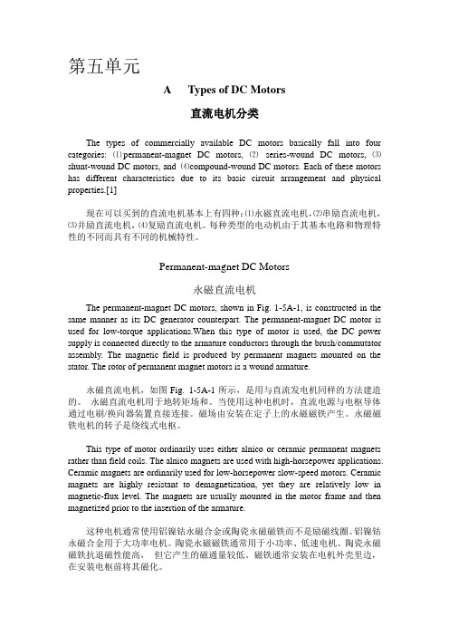
Permanent-magnet DC Motors永磁直流电机The permanent-magnet DC motors, shown in Fig. 1-5A-1, is constructed in the same manner as its DC generator counterpart. The permanent-magnet DC motor is used for low-torque applications.When this type of motor is used, the DC power supply is connected directly to the armature conductors through the brush/commutator assembly. The magnetic field is produced by permanent magnets mounted on the stator. The rotor of permanent magnet motors is a wound armature.永磁直流电机,如图Fig. 1-5A-1所示,是用与直流发电机同样的方法建造的。
- 1、下载文档前请自行甄别文档内容的完整性,平台不提供额外的编辑、内容补充、找答案等附加服务。
- 2、"仅部分预览"的文档,不可在线预览部分如存在完整性等问题,可反馈申请退款(可完整预览的文档不适用该条件!)。
- 3、如文档侵犯您的权益,请联系客服反馈,我们会尽快为您处理(人工客服工作时间:9:00-18:30)。
中英文对照外文翻译文献(文档含英文原文和中文翻译)外文文献:DC Motor CalculationsOverviewNow that we have a good understanding of dc generators, we can begin our study of dc motors. Direct-current motors transform electrical energy into mechanical energy. They drive devices such as hoists, fans, pumps, calendars, punch-presses, and cars. These devices may have a definite torque-speed characteristic (such as a pump or fan) or a highly variable one (such as a hoist or automobile). The torque-speed characteristic of the motor must be adapted to the type of the load it has to drive, and this requirement has given rise to three basic types of motors: 1.Shunt motors 2. Series motors 3. Compound motors Direct-current motors are seldom used in ordinary industrial applications because all electric utility systems furnish alternating current. However, for special applications such as in steel mills, mines, and electric trains, it is sometimes advantageous to transform the alternating current into direct current in order to use dc motors. The reason is that the torque-speed characteristics of dc motors can be varied over a wide range while retaining high efficiency. Today, this general statement can be challenged because the availability of sophisticated electronic drives has made it possible to use alternating current motors for variable speed applications. Nevertheless, there are millions of dc motors still in service and thousands more are being produced every year.Counter-electromotive force (cemf)Direct-current motors are built the same way as generators are; consequently, a dc machine can operate either as a motor or as a generator. To illustrate, consider a dc generator in which the armature, initially at rest, is connected to a dc source E s by means of a switch (Fig. 5.1). The armature has a resistance R, and the magnetic field is created by a set of permanent magnets.As soon as the switch is closed, a large current flows in the armature because its resistance is very low. The individual armature conductors are immediately subjected to a force because they are immersed in the magnetic field created by the permanent magnets. These forces add upto produce a powerful torque, causing the armature to rotate.Figure 5.1 Starting a dc motor across the line.On the other hand, as soon as the armature begins to turn, a second phenomenon takes place: the generator effect. We know that a voltage E o is induced in the armature conductors as soon as they cut a magnetic field (Fig. 5.2). This is always true, no matter what causes the rotation. The value and polarity of the induced voltage are the same as those obtained when the machine operates as a generator. The induced voltage E o is therefore proportional to the speed of rotation n of the motor and to the flux F per pole, as previously given by Eq. 5.1:E o = Zn F/60 (5.1)As in the case of a generator, Z is a constant that depends upon the number of turns on the armature and the type of winding. For lap windings Z is equal to the number of armature conductors.In the case of a motor, the induced voltage E o is called counter-electromotive force (cemf) because its polarity always acts against the source voltage E s. It acts against the voltage in the sense that the net voltage acting in the series circuit of Fig. 5.2 is equal to (E s - Eo) volts and not (E s + E o) volts.Figure 5.2 Counter-electromotive force (cemf) in a dc motor.Acceleration of the motorThe net voltage acting in the armature circuit in Fig. 5.2 is (E s- E o) volts. The resulting armature current /is limited only by the armature resistance R, and soI = (E s- E o)IR (5.2)When the motor is at rest, the induced voltage E o= 0, and so the starting current isI = E s/RThe starting current may be 20 to 30 times greater than the nominal full-load current of the motor. In practice, this would cause the fuses to blow or the circuit-breakers to trip. However, if they are absent, the large forces acting on the armature conductors produce a powerful starting torque and a consequent rapid acceleration of the armature.As the speed increases, the counter-emf E o increases, with the result that the value of (E s—E o)diminishes. It follows from Eq. 5.1 that the armature current / drops progressively as the speed increases.Although the armature current decreases, the motor continues to accelerate until it reaches a definite, maximum speed. At no-load this speed produces a counter-emf E o slightly less than the source voltage E s. In effect, if E o were equal to E s the net voltage (E s—E o) would become zero and so, too, would the current /. The driving forces would cease to act on the armature conductors, and the mechanical drag imposed by the fan and the bearings would immediately cause the motor to slow down. As the speed decreases the net voltage (E s—E o) increases and so does the current /. The speed will cease to fall as soon as the torque developed by the armature current is equal to the load torque. Thus, when a motor runs at no-load, the counter-emf must be slightly less than E s so as to enable a small current to flow, sufficient to produce the required torque.Mechanical power and torqueThe power and torque of a dc motor are two of its most important properties. We now derive two simple equations that enable us to calculate them.1. According to Eq. 5.1 the cemf induced in a lap-wound armature is given byE o = Zn F/60Referring to Fig. 5.2, the electrical power P a supplied to the armature is equal to the supply voltage E s multiplied by the armature current I:P a = E s I (5.3)However, E s is equal to the sum of E o plus the IR drop in the armature:E s = E o + IR (5.4)It follows thatP a= E s I= (E o + IR)I=E o I + I2R (5.5)The I2R term represents heat dissipated in the armature, but the very important term E o I is the electrical power that is converted into mechanical power. The mechanical power of the motor is therefore exactly equal to the product of the cemf multiplied by the armature currentP = E o I (5.6)whereP = mechanical power developed by the motor [W]E o= induced voltage in the armature (cemf) [V]I = total current supplied to the armature [A]2. Turning our attention to torque T, we know that the mechanical power P is given by the expressionP = nT/9.55 (5.7)where n is the speed of rotation.Combining Eqs. 5.7,5.1, and 5.6, we obtainnT/9.55 = E o I= ZnFI/60and soT =Z F I/6.28The torque developed by a lap-wound motor is therefore given by the expressionT =Z F I/6.28 (5.8)whereT = torque [N×m]Z = number of conductors on the armatureF = effective flux per pole [Wb]*/ = armature current [A]6.28 = constant, to take care of units[exact value = 2p]Eq. 5.8shows that we can raise the torque of a motor either by raising the armature current or by raising the flux created by the poles.Speed of rotationWhen a dc motor drives a load between no-load and full-load, the IR drop due to armature resistance is always small compared to the supply voltage E s. This means that the counter-emf E s is very nearly equal to E s.On the other hand, we have already seen that Eo may be expressed by the equationE o = Zn F/60Replacing E o by E s we obtainE s = Zn F/60That is,wheren = speed of rotation [r/min]E s = armature voltage [V]Z = total number of armature conductorsThis important equation shows that the speed of the motor is directly proportional to the armature supply voltage and inversely proportional to the flux per pole. We will now study how this equation is applied.Armature speed controlAccording to Eq. 5.8, if the flux per pole F is kept constant (permanent magnet field or field with fixed excitation), the speed depends only upon the armature voltage E s. By raising or lowering E s the motor speed will rise and fall in proportion.In practice, we can vary E s by connecting the motor armature M to a separately excited variable-voltage dc generator G . The field excitation of the motor is kept constant, but the generator excitation I x can be varied from zero to maximum and even reversed. The generator output voltage E s can therefore be varied from zero to maximum, with either positive or negative polarity. Consequently, the motor speed can be varied from zero to maximum in either direction. Note that the generator is driven by an ac motor connected to a 3-phase line. This method of speed control, known as the Ward-Leonard system, is found in steel mills, high-rise elevators, mines, and paper mills.In modem installations the generator is often replaced by a high-power electronic converter that changes the ac power of the electrical utility to dc, by electronic means.What happens to the dc power received by generator G? When G receives electric power, it operates as a motor, driving its own ac motor as an asynchronous generator!* As a result, ac power is fed back into the line that normally feeds the ac motor. The fact that power can be recovered this way makes the Ward-Leonard system very efficient, and constitutes another of its advantages.Rheostat Speed ControlAnother way to control the speed of a dc motor is to place a rheostat in series with the armature . The current in the rheostat produces a voltage drop which subtracts from the fixed source voltage E s, yielding a smaller supply voltage across the armature. This method enables us to reduce the speed below its nominal speed. It is only recommended for small motors because a lot of power and heat is wasted in the rheostat, and the overall efficiency is low. Furthermore, thespeed regulation is poor, even for a fixed setting of the rheostat. In effect, the IR drop across the rheostat increases as the armature current increases. This produces a substantial drop in speed with increasing mechanical load.中文译文:直流电动机的计算概述现在,我们对直流发电机有一个很好的了解,我们可以开始对直流电动机的研究了。