CREE XT-E测试数据
ATSE测试报告

测试日期: 4/8/2013(1)A电源转B电源及B电源转A电源通断时间测试1. 测试条件1.1 测试方法为在A B电源的最大开距处加一块导通铜片作为导通信号。
1.2 更改合闸线圈,脱扣线圈及脱扣弹簧,合闸线圈弹簧用8TY.282.115/42图号。
1.3 动触头弹簧前端用原TBBQ6-400的弹簧,后端为增大压力弹簧。
图号见附表。
1.4 测试示意图如下:2. A电源转B电源及B电源转A电源通断时间2.1 A分B合(A B电源初始状态:A电源闭合B电源断开。
结束状态:A电源断开B电源闭合)。
2.1.1 测试条件:2.1.1.1 测试位置: A电源的N相,B电源的N相。
2.1.1.2 示波器波形“1”代表A电源的N相,“2”代表B电源的N相。
2.1.1.3 波形图中“a"“b" "c" "d"意义。
“a"代表A电源N相开始动作断开时间。
“b"代表A电源N相完全断开时间。
“c"代表B电源N相开始动作闭合时间。
“d"代表B电源N相完全时间。
2.1.2 测试数据如下:条件:未更换合闸线圈弹簧测试数据(压簧图号:8TY.282.003)a->b时间a->c时间b->c时间a->d时间18.8ms 64ms 55.2ms 76ms27.6ms 64ms 56.4ms 74.8ms312.4ms 65.6ms 53.6ms 76ms49.6ms 61.6ms 52ms 77.6ms测试报告实验次数A电源N相分开至B电源N相闭合通断时间变化曲线2.2 B分A合(A B电源初始状态: B电源闭合A电源断开。
结束状态: B电源断开A电源闭合)。
2.2.1 测试条件:2.2.1.1 测试位置: A电源的N相,B电源的N相。
2.2.1.2 示波器波形“1”代表A电源的N相,“2”代表B电源的N相。
科锐xte 中文说明
科锐xte 中文说明
产品说明
X Lamp®X T-E采用Cree的行业标准XP/XT封装,是Cree性能最佳的以碳化硅为基底材料的LED技术。
X T-E白光LED设定了新的高性能标准,显著降低了系统成本。
X T-E宝蓝色LED是Cree性能最佳的宝蓝色光源,适用于非接触式荧光粉的应用。
Cree XL-amp LED为各类照明应用带来了卓越的照明性能与照明质量,这些应用包括非接触式荧光粉照明、变色照明、便携式照明和个人照明、室外照明、室内定向照明、运输照明、舞台照明、演播室照明、商业照明和应急车照明。
特点
·有白色、最低80-CRI白、最低
70-CRI白及宝蓝色等光色可选
·暖白色有最小显色指数85和90可
·新增特点:可以提供2200KCC
·在85°C时分档
·冷白光效最高达148 lm/W
(85°℃.350mA时)
·带墙上灯座的宝蓝色光效最高达5
(85°C、350mA时)
·视角:115-140°
·热阻:5C/W
·最大驱动电流:1.5A。
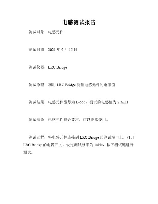
电感测试报告
修编旳六大方面
统一材机库数据原则 统一各专业消耗量定额旳材料旳体现形式 统一计费基础、简化计费程序 周转性材料由摊销改为租赁方式编制 承前启后、推陈出新 相对平衡了各专业间交叉旳定额子目消耗量水平
二、建安费用构成及 计价规则
2023定额构成
分部分项工程费构成
人工费 材料费 机械费 管理费 利润
合用范围
机械台班定额
总则-1
总则-2
总则-3
施工机械台班单价旳费用构成
施工机械台班费用计算措施
基本要求
计算措施-基本要求
计算措施-基本要求
计算措施-折旧费
计算措施-折旧费
计算措施-检修费
计算措施-维护费
计算措施-安拆费及场外运送
计算措施-人工费、燃料动力费
计算措施-其他
其他项目费-计算措施
其他项目费-计算措施
规费与税金
规费与税金
对比
03定额
13定额
1、规费涉及:涉及工程排污费、工程 定额测定费、社会保障及劳动保险费。 2、其中社会保障及劳动保险费涉及: a、养老保险统筹金,b、失业保险费, c、医疗保险费,d、危险作业意外伤 害保险,e、劳动保险费。 3、计算: 社会保障及劳动保险费=分部分项工程 费旳人工费总和*26%
1、规费涉及:涉及社会保险费、住房公积 金、残疾人确保金、危险作业意外伤害险、 工程排污费。 2、计算: (1)社会保险费、住房公积金、残疾人确 保金=(分部分项定额人工费+单价措施定 额人工费+其他项目定额人工费)*26% (2)危险作业意外伤害险=(分部分项定 额人工费+单价措施定额人工费+其他项目 定额人工费)*1%
新工艺、新技术、新原则、新材料不断涌现; 工程计价要素:人工、材料、机械价格不断上涨; 越来越多旳调价、增补定额子目、、、、、、
费思FT6300A系列中小功率电子负载用户手册适用型号(FT6301A-FT6306A)

本手册版权归费思科技所有。手册中包含的信息,仅供用户参考,如有更改,恕不另行通知。对本手 册可能包含的错误或由提供、执行和使用本手册所造成的损害,费思科技恕不负责。
有关产品的最新信息,请登录费思科技网站查询。
产品保证
费思科技保证FT6300A系列电子负载的规格和使用特性完全达到手册中所声称的各项技术指标,并对本 产品所采用的原材料和制造工艺均严格把关,确保产品稳定可靠。
II
安全标识
在本产品外壳、用户手册所使用国际符号的解释请参见下表。
III
目录
前言........................................................................................................................................... I 通告........................................................................................................................................... I
第 2 章 安装.......................................................................................................................................... 11
2.1 验货.................................................................................................................................. 11 2.2 清洁..................................................................................................................................12 2.3 安装..................................................................................................................................12 2.4 输入要求..........................................................................................................................12
微带单极子天线

微带单极子天线设计报告设计者:郑州(2009022052)邱玲(2009022043)胡克强(2009022060)丘定升(2009022050)郭昭君(2009022081)目录1、基本原理 (3)2、设计目标 (3)3、电磁场仿真 (4)(1)3D模型 (4)(2)仿真曲线 (4)4、电路版图设计 (5)(1)、CAD 图 (5)5、安装调试 (6)(1)实物图 (6)(2)测试曲线 (6)6、分析总结 (6)1、基本原理单极子天线是由直接垂直安装在地面或导电平面上的直导体组成的天线 。
单极子天线等效为一振子天线 单极子天线(λ41=h )的方向图E 面2、设计目标⏹ 频率:1800~2200MHz⏹ 增益:0dBi⏹极化方向:垂直⏹方位:全向⏹仰角:球面覆盖⏹电压驻波比:≤2:1⏹阻抗:50ohm⏹最大输入功率:20W⏹接头:SMA-K3、电磁场仿真(1)3D模型(2)仿真曲线4、电路版图设计(1)、CAD 图5、安装调试(1)实物图(2)测试曲线6、分析总结根据最终测试结果分析,此次设计基本达到了设计指标,实物数据与仿真结果一致。
虽然此次设计已经达到要求,但仍有许多不足:(1)、在接下来的学习中,我们应更多地运用ADS、HFSS等专业软件,已达到熟练掌握的程度。
(2)、在完成设计的基础上,要更深入地理解天线的工作原理,增强理论知识。
(3)、将实验设计与实际应用相结合,以便于更好地将其投入生产生活中。
Cree XLamp MC-E高功率LED系列应用注意事项说明书

Application NoteQuickly setup your LED Lighting solution with Cree® XLamp® MC-E series Star BoardBy: Suresh ChaudhariThis application note describes how to select Cree XLamp MC-E star board series and covers the complete lighting solution include selection of driver, optics and heatsink.At the end would like to focus on some design tips and demo setup.Table of ContentsIntroduction of Cree® XLamp® MC-E High Power LED1. (1)Cree® Star board with major features and parameters2. (2)How to select Star board based on the system requirement3. (3)Suppliers recommendation for Driver4. (4)Suppliers recommendation for Optics5. (5)Suppliers recommendation for Heatsink6. (6)Design and Application tips7. (6)Demo Setup8. (7)1. Introduction of Cree® XLamp® MC-E High Power LEDThe XLamp MC-E LED is a lighting-class, multi-chip LED that provides high lumen output in a small footprint package. Compared to discrete LEDs, XLamp MC-E LEDs reduce the distance between LED die, creating a small optical source for excellent optical control and efficient color mixing. XLamp MC-E LEDs can reduce LED system complexity by reducing the number of components required.Cree XLamp LEDs bring high performance and quality of light to a wide range of lighting applications, including color-changing lighting, portable and personal lighting, outdoor lighting, indoor directional lighting, and entertainment lighting.Cree MC-E White LED Cree MC-E Color LEDFEATURES∙ Available in white (2600 K – 10,000 K CCT), EasyWhite™, or color (RGBW) ∙ ANSI-compatible neutral and warm white chromaticity bins ∙ Individually addressable LEDs∙ Maximum drive current: 700 mA per LED die ∙ Reflow solderable – JEDEC J-STD-020 ∙ Electrically neutral thermal path ∙RoHS and REACH-compliant2. Cree® Star board with major features and parametersFEATURES∙ 430 lm @ 350mA∙ 700mA - Max Drive Current∙ 12.8V - Typ. Forward Voltage @ 350mA (For series configuration) ∙ 13.6V - Typ. Forward Voltage @ 700mA (For series configuration) ∙ 4-Chip In Series and parallel Circuit ∙ 4-Chip Individually Addressable∙ Star board available in single color – Cool white, Neutral white and Warm white ∙no need of reflowBelow table shows different types of Star board LED configuration, depending on requirement customer can choose series, parallel or individual configuration. As an example we have selected 3 LED in different configuration.Each LED VF(typ)@350mAViewing Angle MCE4WT-A2-0000-00M02-STARIND Individual (Figure3) M 430 MCE4WT-A2-0000-00K02-STARSRSeries ( Figure1) K 370MCE4WT-A2-0000-00M02-STARPstar Parallel (Figure2) 2mm Cool White WC,WD,WG,WF M4303.2V 110deg3. How to select Star board based on the system requirementLED is available in single die or multi die, depending on its application and lux requirement either of them can be selected. Example, Cree MCE series having 4 die in a single chip means you will get more lumens output in a small footprint package so you can use for microscope illumination, high end strobe light like applications.While selecting LED Module please check below parameters as per your application requirement.∙Configuration – Series, parallel and Individual∙ Lumen output∙Output current∙Maximum output power∙Size and dimension∙ Efficiency∙When you selecting LED module please select radiation pattern Lambertain, batwing and side emitting which matches to your application. If the LED is not available in this pattern, then you can use optics to get the required output.Please also ensure whether for your application required binned LED or full distribution, for this example we are not using bin LED as application is not demanding. Depending on application you can select which bin you require like – forward voltage, color, and flux bin.Explained below with an example how to select MC-E star module as per system requirementExample - High Strobe lightingSpecification-1 meter @ 5000 lux.To get 5000 lux at 1 meter, need almost 330lm source.Here we consider height 1meter, viewing angle 14° and overall efficiency 70%.To get 330 lm source alteast need to use 3-4 LED and optics for each led, but with the use of MC-E LED the number of optics, size of MCPCB and manufacturing hours in assembling will reduce to bring down total system cost. Same explained in below picture.Part Number selected for design,Cree MC-E LED - MCE4WT-A2-0000-00K02-STARSRFraen lens - FRC-N1-MCE-0RFind the central spot “on-axis intensity” value from Fraen datasheet.Narrow Beam (Part Number: FRC-N1-MCE-0R), value is 14If the Fraen narrow reflector FRC-N1-MCE-0R is used on a cool white MC-E LED at 350 mA, the typical luminous flux of the “Group K” LED is 370 lumens.The calculation is:(14 candela/lumen) x (370 lumens) = 5180 candela peak on-axis.1 candela at 1-meter distance produces 1 Lux. This means the peak intensity at 1 meter will be 5180 lux.The intensity decreases as a function of the distance squared, so at 2 meters the peak intensity will be 5180 / (22) = 1295 lux. At 3 meters distance, the peak intensity will be 5180 / (32) = 575 lux.Range 1meter 2 meter 3 meter Illuminance 5180 lux 1295 lux 575 luxWith the help of effective reflector can achieve long beam distances (example- 200 meter).Beam photographsOnce you complete the testing and get required output, then you can paste star board with adhesive to heatsink. Then finally this assembly can be fixed with enclosure as a finished product.4. Suppliers recommendation for DriverIf the power consumption of an LED module is higher than the power of a single LED driver when designing, we can use several LED drivers or an external MOSFET to drive the module.LED drivers may need to work with various power supply voltages in illumination circuits, and it may therefore, be better to select an LED drivers that support a wide range of input voltage in order to mitigate any voltage fluctuation problems.Several suppliers including National Semiconductor, Maxim, Zetex and in driver module LIGHTECH and Lumidrives can offer relevant solutions to meet different applications requirements.Cree LED Array Vout, Iout, and Power driver requirements as below.Vout Iout (max) PowerMCE4WT-A2-0000-00K02-STARSR 13.6V 700mA 9.52WLED Driver Selection consideration∙Voltage and Current rating of driver to be selected as per LED’s configuration whether array configuration in Serial, parallel and Individual combination.∙ Efficiency∙Depends on input LED driver topology to be selected–Dc Input -Buck, Boost, Buck-Boost,–AC Input – Flyback, forward, LLC.Depending on the input voltage and output power the choice can be made for LED driver, canbe buck type, boost type, buck/boost type, and also charge-pump type. For power line drivensystem the buck type is chosen, for the single cell battery operated devices the boost type ischosen, for the system which run on both powerline and battery the buck/boost is chosen.Charge pump type is preferred if the output power is less and EMI and other noise issues.Table below show lists of drivers that meet Cree LED Array’s output voltage, output constantcurrent, and power requirements.LED Driver Selection Guide (Iout = 700mA)NOC FOCNational Semiconductor LM3407MY/NOPB350 mA, Constant CurrentOutput Floating BuckSwitching Converter forHigh Power LEDs from thePowerWise® Family4.5V to 30V350mA0.45V to27VBuck78M77351555100Zetex ZXLD1350ET5350mA LED driver withinternal switch7V to 30V 350mA 30V Buck05M21751226470Maxim MAX16803ATE+2MHz, High-BrightnessLED Drivers withIntegrated MOSFET andHigh-Side Current Sense6.5V to 65V700mA63 Buck89K32471552873*LIGHTECH 901010700PLED 10W driver 120-240Vac700mA15V Module73R3502 1797597* Lumidrives MDU9-SC-3570 LED Driver Power Supply 110-240Vac350/700mA4-32V Module20M5601 1712028* Note- Highlighted parts are LED module5. Suppliers recommendation for OpticsSecondary optics is used to modify the output beam of the LED such that the output beam of the finished lamp will efficiently meet the desired photometric specification.How to select the optics∙What is viewing angle required.∙Select beam ( narrow, medium, wide)∙Select radiation pattern ( Batwing, Lambertain, side emitting)∙If you know Illuminance + distance then you can calculate what is angle you need to select for lensTable below show lists of lens that suit with Cree MC-E LED.FOCLedil FA10613_LM1-RSLENS, REAL SPOT,CREE MCE ±10.5° 79R63001817542Fraen FRC-N1-MCE-0RFRC Series 35mm Diameter Reflectors14° - - Ledil FA10680 _CMC-OLENS, OVAL,CREE MCE ±21° x ±10° 79R63211817549Ledil C10686_EVA-MC-WLENS, WIDE, CREEMCE±18.2°79R6139 18175606. Suppliers recommendation for HeatsinkThermal resistance is a measure of the ability of the package to conduct heat from the chip to the environment.How to select the Heatsink∙ Heatsink thermal resistance value should be equal or lower than calculated value ofthermal resistance of board to ambient i.e. Rth(b-a). The lower the value, the higher the thermal performance.∙ Heat sinks should be designed to have a large surface area, use large number of finefins.∙ Material selection - Aluminium is the most common material used as a heat sink.Table below show lists of Heatsinks that equal or less than to Cree MC-E LED thermal resistance.COOLIANCE CML8001-52-10-101 LED HEAT SINK 3°C/W 99R47231847864 WAKEFIELD SOLUTIONS882-100ABLED HEAT SINK2.88°C/W96M8765-Heatsink can be customized as per end product design requirement.7. Design and Application tipsIn order to determine LED systems reliability the system designer must consider thepossible failure modes for each component. It is generally known that one of the weakest parts of an LED system is the LED driver due to the number and types of components they contains and so covered below point which effect LED drivers reliability.An LED drivers’ reliability depends upon:∙The number and quality of components used within the driver design∙Rated wattage of the driver.∙The maximum operating temperature of the electrolytic capacitors used in the driver.∙The overall efficiency of the AC-DC and DC-DC stages of the driver.∙Good driver design where component placement is determined by safety, EMC and thermal considerations.∙ A suitable thermal management system for the driver such as an aluminium case or forced air cooling fan if appropriate.The maximum LED junction temperature (Tj) provided in the data sheet, example Tj-150°C, so at certain ambient temperature you may need to back off the current so thatyou don’t exceed the maximum Tj, always refer d-rating curve graph to know what is the value of ambient and current on particular thermal value.LED drivers are typically constant current drivers that provide stable current for a single LED or LED array. LEDs used in the applications described are usually high-power LEDsof 1W or greater. These high power LEDs can produce a considerable amount of heat inoperation. This heat, if unmanaged, can degrade the lifetime, light output, forward voltageand most importantly dominant wavelength, which shifts with temperature and therefore itis advisable to consider this and incorporate sufficient thermal management into the design. Some of the Drivers work in conjunction with temperature sensors to achieve thethermal protection and management so as to improve the performance of LEDs in a variety of applications.8. Demo SetupBelow set up done for MC-E series star board.To complete the set up need∙Power supply source ( used 24V,1A rating)∙Constant Current LED Driver ( used LM3404 driver)∙Cree Star Board ( used MCE4WT-A2-0000-00K02-STARSR LED array )About element14element14 is a new, innovative information portal and eCommunity specifically built for electronic design engineers. It provides product data, design tools and technology information, whilst incorporating web 2.0 functionality to facilitate communication, interaction, collaboration and information sharing between colleagues around the world. Users can consult experts, discover trends, post blogs, articles and comments in this world-wide forum.element14 is another innovative offering from Premier Farnell plc (LSE:pfl), FTSE 250, a leader in multi-channel distribution and specialty services for electronic design engineers throughout Europe, the Americas and Asia Pacific. It has a stocked range of 450,000+ products, and access to 4,000,000 more items from 3,500 top manufacturers. The company has group sales of £804.4m and over 4,100 employees globally.For more information about the company, please visit 。
软件检测报告模板

软件检测报告模板篇一:软件测试报告模板软件测试报告模板此页为模板文档本身的版本控制记录表,按模板生成的正式文档中不需要此页。
秘密XXXXXX软件项目系统测试报告软件测试部 200X/XX/XX目录1. 引言 ................................................ ..................... 3 2. 测试参考文档 ................................................ ............. 3 3. 测试设计简介 ................................................ . (3)测试用例设计 ................................................ ....... 3 测试环境与配置 ................................................ ..... 3 测试方........... 4 4. 测试情况 ................................................ ................. 4 测试执行情况 ................................................ ....... 4 测试覆盖 ................................................ ........... 4 缺陷的统计 ................................................ (4)缺陷汇总和分析 .............................. 错误!未定义书签。
具体的测试缺陷 .............................. 错误!未定义书签。
CREE-LM80测试报告

XLamp XP-E White LEDs (Revision 1)1. Number of LED light sources tested /LED光源数量试验See individual test reports.见测试报告2. Description of LED light sources LED光源的描述XLamp XP-E White LEDs (XPEWHT)All measurements provided are LED package measurements.3. Description of auxiliary equipment测试设备描述Instrument Systems ISP-500 Integrating SphereInstrument Systems CAS-140 Spectrometer Keithley 2420 Sourcemeter4. Operating cycle 循环周期LED packages are driven at constant current.5. Ambient conditions 环境条件LED packages are operated in environmentalcontrol chambers. The temperature of theambient air around the LED packages is activelycontrolled by air flowing through the chamber.TA : See individual test reportsRH : < 45%Air flow : 800 CFM 包装是运作了环境控制室。
周围的空气的温度在LED包是乘飞机主动控制流过室。
助教:看个人测试报告湿度,< 45%空气流动:800 CFM立方英尺每分钟6. Case temperature情况下温度The case temperature measurement point is shown inthe XLamp XP-E Soldering & Handling document(AP25). 如此的温度测量点被证明在XLamp XP-E焊接和处理文件(AP25)。