laser
laser
用肉眼去看,全息照片上只有些乱七八糟
的条纹 用一束激光去照射该照片,眼前就会出现 逼真的立体景物 从不同的角度去观察,可 以看到原来物体的不同侧面 每一片碎片都包括被摄物体的完整信息
英女王的全息照片
全息再现用于艺术创作
多路合成角度全息用于艺术品展示
全息激光防伪标签,已经是一个很大的产业
的通信系统,即以大气为媒介的激光通信 系统 两种工作波长:850纳米 1550纳米 850纳米设备便宜,应用于传输距离短的场 合 1550纳米红外光波可被视角膜吸收,照不 到视网膜,可增大传输功率,适用于传输 距离远的场合
自由空间光通信(FSO)的优点
1)快速链路部署—无需埋设光纤等待手续 2)无需频谱许可证 3)带宽高—支持150mb/s到10Gb/s的传输
RGB TV SET
Diode Pumped Laser 转换产生 RGB
Diode Pumped MicroLaser
Diode Pumped MicroLaser
DPL Projection TV
3 : 激光用于通讯
光通信原理示意图
光纤通讯
光通信用的激光器差不多全部是半导体激
速率,传输距离2-4公里 4)安全保密性强 5)协议透明 6)成本低—是光纤到楼的1/10到1/3 7)便 携性
激光 是20 世纪 的四 项重 大的 发明 之一
1:激光的发展史
1958年,贝尔实验室的汤斯和肖洛发表了
关于激光器的经典论文,奠定了激光发展 的基础。 1960年,美国加利福尼亚州休斯航空公司 实验室的研究员梅曼发明了世界上第一台 红宝石激光器。 1965年,第一台可产生大功率激光的器件-二氧化碳激光器诞生。 1967年,第一台X射线激光器研制成功。
激光镭射原理

激光镭射原理
激光镭射(Laser)是一种特殊的光源,具有高亮度、高单色性和高相干性等特点。
激光镭射的产生原理主要是通过受激辐射和光放大来实现的。
在激光镭射的产生过程中,需要一个激活介质来提供辐射能,使得原子或分子处于受激态,然后通过光放大的过程来放大光子,最终产生激光。
激光镭射的产生过程主要包括三个步骤,激活、放大和输出。
首先是激活过程,激活介质受到外部能量的激发,使得原子或分子处于受激态。
在受激态下,原子或分子的能级结构发生变化,能级间的电子跃迁将产生辐射。
接着是放大过程,通过光放大器将受激辐射放大,形成一束相干光。
最后是输出过程,将放大后的光输出为激光。
激光镭射的产生原理需要满足三个条件,首先是激活介质必须具有受激辐射的
能级结构,能够吸收外部能量并处于受激态;其次是需要一个外部能源来提供激活介质的激发能量,常见的外部能源包括光、电、化学和核能等;最后是需要一个光学共振腔来放大激活介质发出的光,形成激光输出。
激光镭射广泛应用于医疗、通信、制造等领域。
在医疗领域,激光镭射被用于
手术刀、激光治疗仪等医疗设备中,具有精准、无创伤的特点。
在通信领域,激光镭射被用于光纤通信、激光雷达等设备中,具有高速、大容量的传输优势。
在制造领域,激光镭射被用于激光切割、激光焊接等工艺中,具有高效、精密的加工特点。
总之,激光镭射的产生原理是通过受激辐射和光放大来实现的,需要满足一定
的条件才能产生激光。
激光镭射在医疗、通信、制造等领域有着广泛的应用前景,将会在未来发展中发挥越来越重要的作用。
激光器及其应用介绍

激光器及其应用介绍激光器(Laser)是一种能产生高度聚束、单色、相干、高能量密度的光束的装置。
它通过激活外部的能量转换装置来产生激光,这种装置可以是光电子元器件、光纤、气体、固体或半导体材料。
激光器的光束特性使其在很多领域都有广泛的应用。
激光器的应用领域非常广泛,下面将对其中的几个主要领域进行介绍。
1.医疗领域激光器在医疗领域有着广泛的应用。
激光手术刀可以通过高度聚焦的激光束进行手术,减少了手术损伤和出血,提高了手术效果。
激光剥蚀术可以用来治疗角膜病变,如近视、远视、散光等。
激光切割术可以用来治疗肿瘤、寻找血管等。
此外,激光器还可以被用来进行皮肤美容,如去除斑点、减少皱纹等。
2.通信领域激光器在通信领域的应用非常广泛。
光纤通信系统中的光源通常使用激光器,它可以产生高强度的单色光束,可以在长距离传输中保持信号强度和质量不变。
激光器还可以通过频率调制技术进行信息传输,实现光纤通信的高速率和高容量。
3.材料加工领域激光器在材料加工领域有着广泛的应用。
激光切割可以用来切割金属、塑料、木材等不同类型的材料。
激光焊接可以用来焊接金属和塑料。
激光打标可以用来在材料表面进行打标和刻字。
激光烧蚀可以用来进行表面清理和剥离。
4.科学研究领域激光器在科学研究领域有着广泛的应用。
由于激光器在时间上的极高分辨率,可以用来进行超快速和超高速的实验研究。
激光器在物理、化学、生物等领域中被广泛应用,用来研究物质的结构和性质。
激光光谱学技术可以用来研究原子和分子的能级结构和光谱特性。
5.军事领域激光器在军事领域有着重要的应用。
激光瞄准器可以用来对准目标,并提供精准的引导和打击。
激光测距仪可以用来测量目标的距离,从而进行精确的射击。
激光通信系统可以用来进行无线通信,提供安全和高效的通信手段。
除了以上几个领域之外,激光器还在很多其他领域中有广泛应用,如环境监测、激光制造、激光显示、激光雷达、激光测绘等。
激光器的研发和应用将为人类的生产生活带来更多的便利和创新。
laser(激光器)——外文原著(大量彩图)第一章
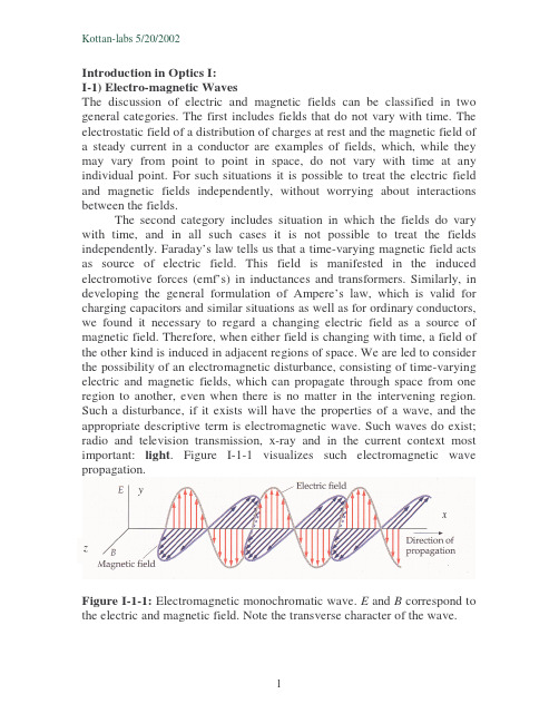
Introduction in Optics I:I-1)Electro-magnetic WavesThe discussion of electric and magnetic fields can be classified in two general categories.The first includes fields that do not vary with time.The electrostatic field of a distribution of charges at rest and the magnetic field of a steady current in a conductor are examples of fields,which,while they may vary from point to point in space,do not vary with time at any individual point.For such situations it is possible to treat the electric field and magnetic fields independently,without worrying about interactions between the fields.The second category includes situation in which the fields do vary with time,and in all such cases it is not possible to treat the fields independently.Faraday’s law tells us that a time-varying magnetic field acts as source of electric field.This field is manifested in the induced electromotive forces(emf’s)in inductances and transformers.Similarly,in developing the general formulation of Ampere’s law,which is valid for charging capacitors and similar situations as well as for ordinary conductors, we found it necessary to regard a changing electric field as a source of magnetic field.Therefore,when either field is changing with time,a field of the other kind is induced in adjacent regions of space.We are led to consider the possibility of an electromagnetic disturbance,consisting of time-varying electric and magnetic fields,which can propagate through space from one region to another,even when there is no matter in the intervening region. Such a disturbance,if it exists will have the properties of a wave,and the appropriate descriptive term is electromagnetic wave.Such waves do exist; radio and television transmission,x-ray and in the current context most important:light.Figure I-1-1visualizes such electromagnetic wave propagation.yxFigure I-1-1:Electromagnetic monochromatic wave.E and B correspond to the electric and magnetic field.Note the transverse character of the wave.The magnitudes of the field vectors E and B are in phase and are related by E =cB ,with01εµ=c ,(I-1-1)where,c (=2.9979246×10⁸m s -1)is the speed of light in the vacuum,where µ0(=1.2566×10⁻⁶Vs V -1m -1)and ε0(=8.8542×10⁻¹²As V -1m -1)are the permeability and permittivity (i.e.,the dielectric constant)of the vacuum.The space (x )and time (t )dependence of the electric and magnetic field is described byE y =E y0sin(kx-ωt )(I-1-2)andB z =B z0sin(kx -ωt ),(I-1-3)where E y0and B z0is the amplitude of the E and B field,respectively;k=2π/λis the wave number and ω=2πν is the angular frequency which depend on the wavelength λand frequency ν,respectively.As shown in figure I-1-1,in vacuum (and air)the E and B fields at any point are in phase.In a dissipative medium,however,a phase shift between the fields takes place.In good conductors,the magnetic field is much larger than the electric field and exhibits a phase delay of approximately 45o .In non-dissipative media,as e.g.glass for visible light,the E and B fields behave similar as in vacuum and are in phase.The energy per photon of a monochromatic (=one color)wave is given byλνchh E ==,(I-1-4)where h is Planck’s constant (=6.626×10⁻³⁴J s),νis the frequency and λis the wavelength.The electromagnetic spectrum is shown in figure I-1-2.Specifically in semiconductor optics the energy is expressed in eV rather than in J.Hence,it is convenient to apply the following relation to convert nm (10-9m)into eV,)nm (1240)eV (λ=E .(I-1-5)Example:One of the possible emissions of an Argon laser is at514.5nm. What is the energy of the emission in nm?Solution:E=1240/514.5=2.41eV.The electromagnetic waves cover an extremely broad spectrum of wavelengths,as shown in figure I-1-2.We can detect only a very small segment of this spectrum directly through our sense of sight from approximately750to430nm.Figure I-1-2:The electromagnetic spectrum.I-2Refraction and ReflectionWe shall begin our introduction in optical phenomena with reflection and refraction at a boundary surface that has been formed by the meeting of two different media.The velocity of light in a medium is below the velocity of light in the vacuum and is given by v=c/n,where n is the refractive index of the medium.We will see that the refractive index does not only determine the light velocity in a medium but it is also an essential parameter for the reflection.Let’s consider that we investigate the directions of the incident, reflected and refracted rays of monochromatic light.We fill find the following results illustrated by Fig.I-2-1:1.The incident,reflected and refracted beams and the normal to thesurface,all lie in the same plane.2.The angle of reflectionφr is equal to the angle of incidenceφa(φr=φa).3.For a given pair of substances,a and b,on opposite sides of the surfaceof separation,the ratio of the sine of the angleφa(between the beam in substance a and the normal)and the sine of angleφb(between the beam in substance b and the normal)is a constant(sinφa/sinφb=constant).If the a beam of monochromatic light travels in vacuum (or air),making an angle of incident φ0with the normal to the surface of a substance a ,we writea aon =φsin sin ,(I-2-1)where n a is the refractive index of substance a .The refractive index is always greater than unity and depends not only on the substance but on the wavelength of the light.I-3Snell’s law of refractionApplying equation (I-2-1)to the to substances a and b in figure I-3-1,we have sin φ0/sin φa =n a and sin φ0/sin φb =n b .Dividing the second equation by the first,we obtain sin φa /sin φb =n b /n a and from this the best known form of Snell’s law of refraction ,n a sin φa =n b sin φb .(I-3-1)The angles in figure I-3-1are independent of the thickness and space between the two plates and are the same when the space shrinks to nothing,as in figureI-3-2.Figure I-3-1:The transmission of light through parallel plates of different substances.The incident and emerging rays areparallel.Figure I-3-2:The figure shows the light rays at the interface of substances a and b without space between the plates.The angles are the same as these in figureI-3-1.Example:In figure I-3-3material a is water and b is glass with index of refraction of 1.52.If the incident ray makes an angle of 60o with the normal,find the directions of the reflected and refractedrays.Solution:Using equation (I-3-1),we find (1.33)(sin600)=(1.52)(sin θb )and θb =arcsin[(1.33)(sin60o )/1.52]=49.3o .I-4Total Internal ReflectionFigure I-4-1shows a number of rays diverging from a point source P in a medium a of index n a and striking the surface of a second medium b of index n b ,where n a >n b.Figure I-4-1:Total internal reflection.The angle of incidence φa ,for which the angle of refraction is 90o ,is called the criticalangle.The angle of incidence for which the refracted ray emerges tangent to the surface is called critical angle φcrit .At this angle φb =90o and Snell’s law becomes n a sin φa =n b ,since sin90o =1.We then have with φa =φcritabcrit sin n n =φ.(I-4-1)For a glass/air interface with n =1.52for the glass,sin φcrit =1/1.52and it follows φcrit =41.1o .The fact that φcrit is less than 45o makes it possible to use a triangular prism with angles 45o ,45o ,and 90o as a totally reflecting surface Such a prism is called Porro prism and is shown in figure I-4-2(a).An application of total internal reflection is shown in figure I-4-2(b).Example:A persiscope uses two totally reflecting 45o -45o -90o prisms.It springs a leak,and the bottom prisms is covered with water.Explain why the periscope no longer works.Solution:The critical angle for water (n b =1.33)on glass (n a =1.52)is φcrit =arcsin(1.33/1.52)=61.0o .The 45o angle of incidence is less than the 61o critical angle for a totally reflecting prism,so total internal reflection does not occur at the glass/water interface.Most of the light is transmitted into the water,and very little is reflected back into the prism.A very important application of total internal reflection is the fiber-optic cable shown in figure I-4-3(a).Figure I-4-3(b)shows the working principle of the cable.When a beam of light enters at one end of the transparent fiber,the light is totally reflected internally and is trapped within therod.Figure I-4-3:(a)Fiber-optic cable,used to transmit a modulated laser beam for communication purposes.(b)The so-called light pipe.The light is trapped by internal reflection,provided that the angles shown exceed the criticalangle.(b)I-5DispersionOrdinarily,white light is a superposition of waves with wavelengths extending through-out the visible spectrum.The speed of light in vacuum is the same for all wavelengths,but the speed in a material substance is different for different wavelengths.Therefore the index of refraction of a material depends on the wavelength.The dependence of the index of refraction on the wavelength is called dispersion .Figure I-5-1shows the variation of the refractive index with the wavelength for different optical materials.The value of n usually decreases with increasing wavelength and thus increases with increasing frequency.Light of longer wavelength usually has greater speed in a material than light of shorter wavelength.The brilliance of diamond is due in part to its large dispersion and in part to its unusually large refractive index (2.417).When you experience the beauty of a rainbow,you are seeing the combined effects of dispersion and total internalreflection.Figure I-5-2shows the ray of white light incident on a prism.The deviation (change of direction)produced by the prism increases with increasing the refractive index and frequency (i.e.,the energy,see equationI-1-4).Refractive IndexbyAlphabetical Listing of MaterialRefractive IndexbyIncreasing RI Value Material RI MaterialRI Air (STP)1.00029Vacuum 1.00000Amethyst (Quartz) 1.54(+1.55)Air (STP) 1.00029Beryl (Emerald) 1.57(+1.60)Water 1.333Citrine1.55Glass 1.517Corundum (Ruby,Sapphire) 1.76(+1.77)Quartz1.54(+1.55)Emerald (Beryl) 1.57(+1.60)Amethyst (Quartz) 1.54(+1.55)Diamond2.417Rock Crystal (Quartz) 1.54(+1.55)Garnet (Pyropes) 1.73-1.75Citrine1.55Garnet (Almandine) 1.76-1.83Beryl (Emerald) 1.57(+1.60)Garnet (Rhodolite) 1.76Emerald (Beryl) 1.57(+1.60)Glass1.517Topaz1.61(+1.62)Peridot (Olivine) 1.65(+1.69)Tourmaline1.62(+1.64)Quartz1.54(+1.55)Peridot (Olivine) 1.65(+1.69)Rock Crystal (Quartz) 1.54(+1.55)Garnet (Pyropes) 1.73-1.75Ruby (Corundum) 1.76(+1.77)Garnet (Rhodolite) 1.76Sapphire (Corundum) 1.76(+1.77)Garnet (Almandine) 1.76-1.83Topaz1.61(+1.62)Ruby (Corundum) 1.76(+1.77)Tourmaline 1.62(+1.64)Sapphire (Corundum)1.76(+1.77)Vacuum 1.00000Corundum (Ruby,Sapphire) 1.76(+1.77)Water1.333'High'Zircon 1.96(+2.01)High'Zircon1.96(+2.01)Diamond2.417Table I-5-1:Refractive index of various materials (from /HTML/Materials3.htm).Note:refractive index listings which have two numbers [ex.1.54(+1.55)]denote materials with double refractionproperties.I-6PolarizationPolarization occurs to all transverse waves.Figure I-6-1illustrates the idea of polarization by showing a transverse wave as it travels long a rope toward a slit.The wave is said to be linearly polarized,which means that its vibration always occur along one direction.Figure I-6-1:The principle of polarization:A transverse wave is linearly polarized when its vibrations always occur along one direction.(a)The rope passes a slit parallel to the vibrations,but(b)does not pass trough a slit that is perpendicular to the vibrations.Linearly polarized light can be produced from unpolarized light with the aid of certain materials.One commercially available material goes under the name of Polaroid.As shown in figure I-6-2,such materials allow only the component of the electric field along one direction to pass through,while absorbing the field component perpendicular to this direction.Light from ordinary sources is not polarized.The“antennas”that radiate light waves are the molecules that makes up the sources.The waves emitted by any one molecule may be linearly polarized.However,any actual light source contains a tremendous number of molecules with random orientations,so the light emitted is a random mixture of waves that are linearly polarized in all-possible directions.In figure I-6-3unpolarized light is incident on a polarizer.The blue line represents the polarizing axis.The E vectors of the incident wave exhibit random directions.The polarizer transmits only the components of E parallel to the polarizing axis.The intensity of the transmitted light is exactlyFigure I-6-3:Unpolarized light is incident on the polarizer.The intensity of the transmitted linearly polarized light,measured by the photocell,is the same for all orientations of the polarizer.half of the incident unpolarized light,no matter how the polarizing axis is oriented.Here’s why:We can resolve the E field of the incident wave into a component parallel to the polarizing axis and a component perpendicular to it.Because the incident light is a random mixture of all states of polarization, these two components are,on average,equal.The(ideal)polarizer transmits only the component that is parallel to the polarizing axis,so half of the incident intensity(I0/2)is transmitted.What happens when the linearly polarized light emerging from a polarizer passes through a second polarizer,as shown in figure I-6-4?To find the transmitted intensity at intermediate values of the angleφ,we bear in mind that the intensity of an electromagnetic wave is proportional to the square of the amplitude of the wave.The ratio of the transmitted to incidentamplitude is cosφ,so the ratio of transmitted to incident intensity is cos2φ. Thus,the intensity of the light transmitted through the analyzer isI=(I0/2)cos2φ,(I-6-1)Where,I0is the maximum light intensity atφ=0.Equation(I-6-1)is called Malus’s law.Figure I-6-4:The analyzer transmits only the component that is parallel to its polarization axis.Example:In figure I-6-4the incident unpolarized light has the intensity I0. Find the intensity transmitted by the first polarizer and the second if the angle between the axes of the two filters is30o.Solution:As explained above,the intensity after the first filter is I0/2. According to equation(I-6-1)with30o,the second polarizer reduces the intensity by a factor cos230o=3/4.Thus the intensity transmitted by the second polarizer is I0/2×(3/4)=(3/8)×I0.Example:What value ofφshould be used in figure I-6-4,so that the average intensity of the polarized light reaching the photocell is one-tenth the average intensity of the unpolarized light?Solution:Using equation(I-6-1),we find I0/10=(I0/2)cos2φ.Solving this relation forφyieldsφ=arccos(1/5)(1/2)=63.4o.A further possibility to create either partially or totally polarized light is by reflection.In figure I-6-5,unpolarized light is incident on a reflectingsurface between two transparent optical materials.The plane containing the incident and reflected rays and the normal to the surface is called the plane of incidence .Figure I-6-5:When light is incident at the polarizing angle,the reflected light is linearly polarized.At one particular angle of incidence,called the polarizing angle θp ,only the light for which the E vector is perpendicular to the plane of incidence is reflected.The reflected light is therefore linearly polarized perpendicular to the plane of incidence (i.e.,parallel to the reflecting surface).In 1812,Sir David Brewster noticed that when the angle of incidence is equal to the polarizing angle θp ,the reflected and refracted ray are perpendicular to each other.The situation is shown in figure I-6-6.In this case θb =90o -θp .Using equation (I-3-1),we find sin θp /sin(90o -θp )=sin θp /cos θp =n b /n a and finally.tan a b n n p =θ(I-6-2)This relation is known as Brewster’s law .Light and other electromagnetic radiation can also have circular or elliptical polarization,i.e.,the E describes a circular or elliptical rotation.In this context polarization by birefringence is important.Birefringence occurs in calcite and other noncubic materials (hence also in various semiconductors)and some stressed plastics and cellophane.Most materials are isotropic ,that is,the speed of light passing through the material is the same in all directions.Because of their atomic structure,birefringent materials are anisotropic .The speed of light depends on its direction of propagation through the material.When a light ray is incident on such materials it may be separated into two rays called the ordinary and extraordinary ray.There is one particular direction in a birefringent material in which both rays propagate with the same speed.This direction is called the optic axis of the material.However,when light is incident at an angle to the optic axis,as shown in figure I-6-7,the rays travel in different directions and emerge separated inspace.If light is incident on a birefringent plate perpendicular to its crystal face and perpendicular to the optic axis,the two rays travel in the same direction but different speeds.The rays emerge with a phase difference that depends on the thickness of the plate and on the wavelength of the incident light.In a quarter-wave plate,the thickness is such that there is a90o phase difference between the waves of a particular wavelength when they emerge. In a half-wave plate,the rays emerge with a phase difference of180o.Suppose that the incident light is linearly polarized such that E is45o to the optic axis,as illustrated in figure I-6-8.The ordinary and extraordinary rays start out in phase and have equal amplitudes.With a quarter-wave plate,they emerge with a phase difference of90o,so the resultant components of E are E x=E0sinωt and E y=E0sin(ωt+90o)=E0cosωt (ω=2πνis the angular frequency and t represents the time).The electric field vector thus rotates in a circle and the wave is circularly polarized.Figure I-6-8:Polarized light is incident on a birefringent crystal such that E makes45o angle with the optic axis,which is perpendicular to the light beam.If the crystal is a quarter-wave plate the light behind the crystal is circularly polarized.Figure I-6-9shows the propagation of circular polarized light.If the advancing wave revolves clockwise(looking toward the source),then it’s said to be right-circularly polarized;if counterclockwise,it’s left-circularly polarized.The magnitude of E remains constant while revolving once around with every advance of one wavelength.With a half-wave plate,the wave emerge with a phase difference of 180o ,so the resultant electric field is linearly polarized with components E x =E 0sin ωt and E y =E 0sin(ωt +180o )=-E 0sin ωt .Hence,the direction of the wave polarization is rotated by 90o relative to that of the incident wave,as shown in figureI-6-10.If the phase difference between the two components of E is something other than a quarter wavelength,or if the two component wave have different amplitudes,the resulting wave is elliptically polarized.I-7Huygens’PrincipleThe principles governing reflection and refraction of light rays,discussed in I-2and I-3,were discovered experimentally long before the wave nature of the light was firmly established.These principles however can be derived from wave considerations and thus shown to be consistent with the wave nature of light.To establish this connection we use a principle called Huygens’principle(Christian Huygens in1678).According to this principle,each point on a given wavefront can be considered to be a point source of secondary wavelets.Figure I-7-1shows the plane wavefront AA’striking a mirror at point A.As can be seen from the figure,the angleφ1between the wavefront and the mirror is the same as the angle of incidenceθ1.From figure I-7-1it isFigure I-7-1:Plane wave reflected at a plane mirror.readily shown that the angle of reflection equals the angle of incidence. Figure I-7-2shows an enlargement of a portion of figure I-7-1showing AP, which is part of the original wavefront.The reflected BB’’makes anangle φ1’with the mirror that is equal to the angle of reflection θ1’between reflected ray and the normal to the mirror.The triangles ABP and BAB’’are both right triangles with a common side AB and an equal side AB’’=BP =ct .Hence,these triangles are congruent and the angles φ1and φ1’are equal,implying that θ1’=θ1.Figure I-7-3shows a plane wave incident on an air/glass interface.We apply Huygen’s construction to find the wavefront of the transmitted wave.The new wavefront BB’is not parallel to the original wavefront AP because the speeds v 1and v 2are different.From the triangle APB ,sin φ1=v 1t /AB or AB =v 1t /sin φ1=v 1t/sin θ1using the fact that φ1=θ1.Similarly,from triangle AB’B ,sin φ2=v 2t/AB or AB =v 2t /sin φ2=v 2t /sin θ2,where θ2=φ2is the angle of refraction.Equating the two values for AB ,we obtain2211sin sin v v θθ=.(I-7-1)Substituting v 1=c /n 1and v 2=c /n 2in this equation delivers Snell’s law,n 1sin θ1=n 2sin θ2.I-8Thin filmsYou have probably noticed the colored bands in a soap bubble or in the film on the surface of oily water.The bands are due to the interference of light reflected from the top to the bottom surfaces of the film.The different colors arise because of the variation in the thickness of the film,causing interference for different wavelength at different points.Such an interference effect is shown in figureI-8-1.We consider now a thin film of uniform thickness d and index of refraction n shown in figure I-8-2.To determine whether the reflected light rays interfere constructively or destructively,we must note the following fact:A wave traveling in a medium of low refractive index (air)undergoes a 180o phase change upon reflection from a medium of higher refractive index.There is no phase change in the reflected wave if it reflects from a medium of lower refractiveindex.dRay 1is reflected from the upper surface A undergoes a phase change of 180o with respect to the incident wave.On the other hand,ray 2,which is reflected from the lower surface B undergoes no phase change with respect to the incident wave.Therefore,ray 1is 180o out of phase with ray 2corresponding to path difference of λn /2.However,we must consider that ray 2travels an extra distance equal to 2d before the waves recombine.Hence,if 2d =λn /2=λ/(2n )the phase difference between both rays is 360o and the waves recombine in phase and constructive interference takes palace.In general,the condition for constructive interference is expressed as2nd =(m +1/2)λ(m =0,1,2,…)(I-8-1)and for destructive interference we have2nd =m λ.(m =0,1,2,…)(I-8-2)Thin films are of considerable importance for the formation semiconductor devices.Almost all optoelectronic devices are composed of the combination of various thin films.Concerning research and development,by means of optical spectroscopy not only the optical or optoelectronic features of semiconductors are investigated but also other features as the film thickness.Hence,in many cases optical characterization methods accompany the manufacturing steps of electronic and optoelectronic devices.For optical thickness measurements,equations (I-8-1)and (I-8-2)can be used to determine the film thickness.According to equation (I-8-2),the fringe of order m lies at λ1and that of order (m +1)at λ2.Hence,we have m λ1=(m +1)λ2so that m =λ2/(λ1-λ2).With (I-8-2)we find,2nd =λ1λ2/(λ1-λ2)and the thickness of the film is)(22121λλλλ−=n d ,(I-8-3)where λ1and λ2is the wavelength of two adjacent maxima or minima in the spectrum.Example:Figure I-8-3shows the transmission spectrum of a thin CdS film on glass.The transmittance starts at the band-gap of the material (≈500nm)and pronounced fringes at 582and 631nm are observed.More details concerning semiconductor will follow in Semiconductor Optics I &II.3003504004505005506006507007500.00.10.20.30.40.50.6582nm631nmT r a n s m i t t a n c e W avelength (nm)Figure I-8-3:Transmittance of thin film CdS on glass at room temperature.Solution:The thin film CdS exclusively causes the fringes in figure I-8-3.The glass substrate does not influence the interference effect.Hence,we insert the wavelengths of the two indicated maxima and n CdS =2.5in equation (I-8-3)and get the thickness of the film,µm 1.5m)10(495m)10m)(63110(582999=××××=−−−d .The calculation of the transmitted and reflected intensities of thin films requires the consideration of the internal reflections.Figure I-8-4shows the concept.I 0is the intensity of the incident beam,R is the reflection coefficient of the surface and backface,αis the absorption coefficient and x the thickness of the film.The transmitted and reflected intensities are summed up with a geometrical series delivering the following results for the transmittance and reflectance,xxe R e R Tr αα2221)1(−−−−=(I-8-4)and}{2α22α2e 1e )(11x x R R R Re −−−−+=.(I-8-5)Figure I-8-4:The transmitted and reflected intensities through a thin film.For many applications,the formulas)}2exp()1(1{2x R R Re α−−+=(I-8-6)and)exp()1(2x R Tr α−−=(I-8-7)are accurate enough.Example:Calculate the transmittance of the film with a thickness of 1µm,an absorption coefficient of 100cm -1and an reflection coefficient of 0.2.Solution:Tr =(1-0.2)2exp(-100cm -1×10⁻⁴cm)≈(1-0.2)2=0.64.We see,in case of effective absorption the reflection of the surface determines the transmission features of the film.。
laser

激光及其在CF中的应用孟祥明一、激光的定义激光LASER,是取自英文Light Amplific ation by Stimulated Emission of Radiation的各单词头一个字母组成的缩写词。
意思是"通过受激发射光扩大"。
1964年按照我国著名科学家钱学森建议将“光受激发射”改称“激光”。
二、激光的产生原理原子中的电子的运动状态可以分为不同的能级,当电子从高能级向低能级跃迁时,会释放出相应能量的光子(自发辐射)。
同样的,当一个光子入射到一个能级并为之吸收的话,会导致电子从低能级向高能级跃迁(受激吸收);然后,部分跃迁到高能级的电子又会跃迁到低能级并释放出光子(受激辐射)。
这些运动不是孤立的,而往往是同时进行的。
当我们创造一种条件,譬如采用适当的媒质、共振腔、足够的外部电场,受激辐射得到放大从而比受激吸收要多,那么总体而言,就会有光子射出,从而产生激光。
三、激光的特点1、高方向性激光光束的发散度极小,大约只有0.001弧度,接近平行。
2、高亮度红宝石激光器的激光亮度,能超过氙灯的几百亿倍。
机构能量密度很大,短时间里聚集起大量的能量。
激光比普通光源高亿万倍,比太阳表面的亮度高几百亿倍。
亮度是衡量一个光源质量的重要指标,若将中等强度的激光束经过会聚,可在焦点出产生几千到几万度的高温。
3、高单色性激光器输出的光,波长分布范围非常窄,因此颜色极纯。
以输出红光的氦氖激光器为例,其光的波长分布范围可以窄到2×10⁻⁹nm,是氪灯发射的红光波长分布范围的万分之二。
4、高相干性激光的频率、振动方向、相位高度一致,使激光光波在空间重叠时,重叠区的光强分布会出现稳定的干涉现象。
四、CF中用到的激光由于激光有很好的方向性和干涉性,用其测量距离,精度高,为了节省空间用现在很成熟的半导体激光器或者He-Ne激光器就可以完成精密测长。
Coater中的异物检测、测长机中的定位。
laser波长范围
Laser波长范围1. 引言激光器是一种产生高强度、高单色性的电磁辐射的装置,其波长范围对于不同应用具有重要意义。
本文将探讨激光器的波长范围及其在不同领域中的应用。
2. 激光器波长分类根据激光器的波长分类,可以将其分为可见光、红外线和紫外线三类。
2.1 可见光激光器可见光激光器是指发射在人眼可见范围内的激光。
根据不同的波长,可见光可以分为红、橙、黄、绿、蓝、靛、紫七个颜色。
常见的可见光激光器包括红宝石激光器(694 nm)、氦氖激光器(632.8 nm)、氩离子激光器(488 nm)等。
这些激光器在医学、交通信号灯以及演出等领域有广泛应用。
2.2 红外线激光器红外线(Infrared)是指位于可见光之外的电磁辐射。
根据波长范围,红外线可以进一步分为近红外、中红外和远红外三类。
近红外波长范围为700 nm至2500 nm,中红外波长范围为2500 nm至8000 nm,远红外波长范围为8000 nm至1 mm。
常见的红外线激光器包括二氧化碳激光器(10.6 μm)、半导体激光器(850 nm)等。
这些激光器在通信、遥感、材料加工等领域具有重要应用。
2.3 紫外线激光器紫外线(Ultraviolet)是指位于可见光之前的电磁辐射。
根据波长范围,紫外线可以分为近紫外、中紫外和远紫外三类。
近紫外波长范围为200 nm至400 nm,中紫外波长范围为100 nm至200 nm,远紫外波长范围为10 nm至100 nm。
常见的紫外线激光器包括氩氟化物激光器(193 nm)、二极管激光器(375 nm)等。
这些激光器在生物医学、光刻等领域有广泛应用。
3. 激光器波长选择的影响因素激光器波长的选择对于不同应用具有重要意义,以下是影响激光器波长选择的几个关键因素:3.1 材料吸收特性不同材料对不同波长的激光具有不同的吸收特性。
例如,二氧化碳激光器的波长为10.6 μm,与许多非金属材料相互作用强烈,适用于材料加工和切割。
激光简介

一、激光简介
产生示意图
在泵浦源的激励下,并有合适的工作物质, 在谐振腔中实现离子束的反转,产生激光
一、激光简介
一般情况下, 绝大多数粒子 处于基态,很 稳定,而激光 产生必须实现 粒子束反转, 即激发态能级 粒子束高于基 态粒子束
原理及其示意图
一、激光简介
1960年,世界上第一台激光器诞生。激光 是一项根本性的突破。激光技术的发展,极 大地带动了相关科学研究的蓬勃发展,带来 了遍及社会和经济生活各个领域的广泛用途。 1971年:激光进入艺术世界,用于舞台光 影效果,以及激光全息摄像。英国籍匈牙利 裔物理学家Dennis Gabor凭借对全息摄像 的研究获得诺贝尔奖。
ห้องสมุดไป่ตู้
四、激光展望
以激光技术为代表的 高技术是国家科技创 新能力的集中体现和 新型产业发展的重要 基础,也是国家经济、 科技和军事竞争制高 点。
制作人: 张韶阳 学院: 物理科学与技术学院 专业: 光信息科学与技术
版权所有,盗版必究
二、激光应用
激光束可以聚焦很 小的光点,有很高 的功率密度,可以 使材料加热汽化, 进行切割,且对切 边热影响很小,基 本没有变形。
二、激光应用
利用准分子激光手术 切削角膜来进行矫正 视力,此技术有一定 的安全性,当然也不 排除风险。
二、激光应用
科研方面:用激光激发某些物质,可以得到与普 通光源不一样的发光现象。进而研究其发光机理。 此外,用激光可以实现干涉衍射等现象,根据出 现的条纹来分析所要的信息
激光简介
激光应用
激光展望
四、激光展望
与原子能、半导体、计算机一同被誉为“20世 纪四大发明”的激光技术,已走过50年发展历 程。未来激光技术将围绕普及、提高、交叉三 个方面加快发展。首先,激光在科学研究、人 民生活、国民经济等方面都会有新的成就。其 次,激光将跃上更新更高的台阶,在功率提升、 波长延伸、能量与速递增长等方面创新研发水 平。另外,激光技术将在物理、化学、材料、 生物、医疗、农业、信息技术等领域得到广泛 的交叉学科应用,成为科技前沿发展的“锐 器”。
光学激光技术缩写
光学激光技术缩写光学激光技术是当今高科技领域中的一个热门话题。
随着科技的不断进步和发展,我们对激光技术的了解和应用也逐渐加深。
在这项技术中,缩写也是非常重要的一部分,因为它们可以帮助人们更好地理解和应用激光技术。
在下面的文章中,我们将详细介绍一些常见的光学激光技术缩写。
1. LASER“LASER”是“激光”这个词的缩写,全称是“Light Amplification by Stimulated Emission of Radiation”(光子放大的受激辐射)。
这个术语最初是由美国物理学家西奥多·曼纳斯创建的,他在1958年首次使用了这个缩写。
今天,“LASER”已经成为了激光技术领域中最常用的缩略词。
2. CO2“CO2”是二氧化碳(Carbon Dioxide)的缩写,当它用于激光技术时,通常表示一种长波红外激光器。
这种激光器的波长可以达到9.4微米到10.6微米,通常用于切割和焊接不同种类的材料,比如钢铁、不锈钢、铝合金等。
3. Nd:YAG“Nd:YAG”是钕掺杂的钇铝石榴石晶体(Neodymium-doped Yttrium Aluminum Garnet)的缩写。
这种晶体通常用于制造固体激光器。
Nd:YAG激光器的波长为1.064微米,被广泛用于医疗、皮秒镭射等领域。
4. Q-switching“Q-switching”是确定激光输出的方法中最重要的技术之一,它通过调节一个叫做“Q开关”的特殊器件来控制激光器的输出。
Q-switching可以使激光器在极短的时间内输出非常高的功率,可用于制造超短激光器、雷达、制造等领域。
5. MOPA“MOPA”是“Master Oscillator Power Amplifier”的缩写,这是一种激光器系统,使用了两个不同的部分:一个被称为主振荡器(Master Oscillator)产生激光,另一个被称为功率放大器(Power Amplifier)将激光增幅到更高的功率。
- 1、下载文档前请自行甄别文档内容的完整性,平台不提供额外的编辑、内容补充、找答案等附加服务。
- 2、"仅部分预览"的文档,不可在线预览部分如存在完整性等问题,可反馈申请退款(可完整预览的文档不适用该条件!)。
- 3、如文档侵犯您的权益,请联系客服反馈,我们会尽快为您处理(人工客服工作时间:9:00-18:30)。
Electrodes
Switching
MIRROR
TEACO2
GAS FLOW
C
High Voltage
For Preionozation
OUTPUT MIRROR
C
FAN MOTOR
BEAM
HEAT EXCHANGER
TEA-CO2
Power
<0.5μs
Time
2to3 us (fixed)
Pulse Period Min. 2ms
10:1
Aspect Ratio
Mechanical Drill
1:1
UV YAG
Thru Vias
CO2
Photo-via
.1:1 500 450 400 350 300 250 200 150 100 50 mm
Blind Vias
3.Microvia 的成型原理
IR 与 UV LASER 的盲孔加工原理是不一样的: • IR——红外线是利用其光束所带的热能,将介质加热至熔融
各种激光的光波图
Light spectrum
5th H, 4th H, 3rd H, Ar-Ion 2nd H, Nd:YAG Nd:YAG Nd:YLF Nd:YAG Nd:YAG Nd:YAG
1000 nm 100 nm 212 nm 355 nm 488 nm 532 nm
10,000 nm
25 mil Pad
8 mil Pad
3 mil Hole
10 mil Through Hole
HITACHI &SUMITOMO
Outer Layer Alignment
1.对位标靶---圆形 2.对位补偿类似ESI
光学系统
Laser Beaestores laser beam to vertical
Pulse Rep. Rate:Max. 500Hz
RF Excited CO2 Laser Output Window
‘Front’
‘Rear’ Mirror
Mirror
High Rep Rate RF Excited Slab Laser 1 to 100 μs (Variable)
Peak Power
B、激光发生原理
产生条件: • 激发介质:气体、固体、半导体等 • 激发能量:光能、电压、电流等 • 共鸣器 :反射镜、折射镜
常见的LASER激发方式
1) LASER 类型——UV 激发介质——YAG 激发能量——发光二极管 代表机型:ESI 5320 2) LASER 类型—— IR(RF) 激发介质——密封CO2气体 激发能量——高频电压 代表机型:HITACHI LC-1C21E/1C 3) LASER 类型—— IR(TEA) 激发介质——外供CO2气体 激发能量——高压电极 代表机型:SUMITOMO LAVIA 1000TW
Std. Application 1 to 30 μs
TIME
Pulse Period min. 0.25ms(Varible)
Summary
ESI 5320
高频率低功率脉冲
固态激光激发装置,无须外部供气
“冷光”,产生热量少
Hitachi
RF Excited 密封气体激发 无须定期换气
Pulse Width Pulse Height Pulse Frequency Range Beam Mode Pulse to Pulse Stability - 30ns - > 15kW - 020,000pps - TEMoo - <6%
30ns
-Executor of Laser
HR Mirror
UV
1 0.9 0.8 0.7 0.6 0.5 0.4 0.3 0.2 0.1 0
VISIBLE
IR
Resins vary in the IR based on additives. Can be almost transparent.
Total Absorption
FR4 Matte Cu Glass
Max.± 5%
Item\Machine Gas Supply Gas Change Laser Mounting Beam Mode Gas component
Hitachi N/A(sealed)
Sumitomo ESI External Gas No Container Sealed Gas Periodic Life:10,000Hr Gas Change No Bulit-in Separate Unit Bulit-in Single Multi \ H2,CO,CO2 \ N2,He
YAG
CO2
四、LASER 钻机介绍
KPIII现有三种laser钻机
•HITACHI
•ESI
(LC-1C21E/1C)
•SUMITOMO (LAVIA 1000TW) (5320)
LASER 特点 对位系统 钻孔特点
Laser 特点
-Executor of Laser
HR Mirror
355nm Diode Pumped UV YAG Laser
每四小时需做精度校正
SUMITOMO
外部供气
须定期换气 加工时有能量检测和补打功能
-Laser Parameters
Item\Machine Type Ë ¦ PW PE f(Hz) Pk Pulse Energy Energy Stability Hitachi Super pulse CO2 Laser 9.4us 1 to 100 us 5mJ 100-4000 0.5kW 5mJ Sumitomo Tea-CO2 Laser 9.3us 0.2us 130mJ 500 200kW 130mJ Max.± 5% ESI Diode- pumped Laser 0.355us 0.04us 5-20,000
-Optical System ESI
Upcollimator Imaging Scan Lens
UV Laser
Beam Shaper
Galvos
Sample or Work Piece
Before beam shaper
After beam shaper
After aperture
HITACHI
Layer 2 Alignment Mark
Panel Alignment Techniques
4 points allow correction of x - y offset, rotation, scale, and keystone
Improved Design Rules with Laser Registration
UP (1.5/1)
2.Positioning and Drilling
--REGISTRATION & BEAM POSITIONER --DRILLING MODE --SPEED
-REGISTRATION ESI
Inner Layer Alignment
Laser used to expose buried alignment targets
Focuses laser beam on work surface
Long working Distance
Galvo Mirror Angle Feed Back System
Capacitive Sensor
Mirror
Scanner
Monitor angle
355nm Diode Pumped UV YAG Laser
Output Beam Beam Coupler Splitter Dump
SHG X-tal THG X-tal
QSw
Nd:YAG
1064nm
Laser Diode Bar
532nm
355nm
355nm Output
TEA-CO2
ELECTRODES
Long-Chain Molecules
Particles Forcefully Ejected
Absorption
Bond Breaking
Ablation
Ablation Versus Vaporization
ULTRAVIOLET VISIBLE INFRARED
4TH Harmonic of YAG
Copper is reflective
0.2 0.3 0.4 0.5 0.6 0.7 0.8 0.9 1 1.1 1.2
Wavelength (microns)
Glass is transparent
由于不同材料对各类激光的吸收均不相同,导致 LASER加工混合材料时的困难。
各种孔加工方法的范围
2.常见LASER的加工材料
Epoxy FR4 ARAMI COPPER BT
现KPIII已加工的介质材料包括:
RCC、1X1080、2X1080、2116、2X10⁶、ARAMI
Absorption Curves of PWB Materials
Strong absorption in all materials
Solid 3rd 351~355nm 10~150ns 0.1~5mj 1~520KHz 10~20KW 1~5W Õ 20~100¦ m 0.1~10¦ m ¦ Ì Ì Harmonic Laser ExcimerLaser 248NM 20~30NS 200~400MJ 1~300Z 15~20MW 80~200W Õ 2um-2mm 0.1~0.5¦ m ¦ Ì
状态,并达到气化,最后除去成孔,从而形成Micro-via。