TAPPIT822OM-2011
NetBotz

将传感器连接到 Sensor 端口.................................... 9 连接警报信号灯和其他可选设备................................. 10 将传感器和传感器盒连接到 A-Link 端口 ......................... 11
NetBotz 快速配置 ............................................ 18
配置装置设置 . . . . . . . . . . . . . . . . . . . . . . . . . . . . . . . . . . . . . . . . . . . . 18 配置警报操作 . . . . . . . . . . . . . . . . . . . . . . . . . . . . . . . . . . . . . . . . . . . . 19
传感器规格................................................... 29
担保 ................................................................................. 30
两年期出厂担保............................................... 30
NetBotz 配置向导 ............................................ 15
NetBotz 机架监视器 450/550/570 安装和快速配置手册
i
访问装置..................................................... 15
AT9220系列综合安规测试仪用户手册

Rev.A 2.0固件说明:适用于主程序Rev.A 2.0及以上的版本AT9220系列综合安规测试仪ACW额定输出: 5kV / 20mADCW额定输出: 6kV / 10mAIR额定输出:1kV / 10GΩ直流快速放电、触电保护和电弧侦测功能999.9秒内任意设定的电压上升时间、测试时间、下降时间可存储、编辑10组测试组,每组16步HANDLER ( PLC ) 接口RS-232C接口& % 安柏®是常州安柏精密仪器有限公司的商标或注册商标。
安全须知当你发现有以下不正常情形发生,请立即终止操作并断开电源线。
立刻与安柏科技销售部联系维修。
否则将会引起火灾或对操作者有潜在的触电危险。
●仪器操作异常。
●操作中仪器产生反常噪音、异味、烟或闪光。
●操作过程中,仪器产生高温或电击。
●电源线、电源开关或电源插座损坏。
●杂质或液体流入仪器。
安全信息为避免可能的电击和人身安全,请遵循以下指南进行操作。
免责声明用户在开始使用仪器前请仔细阅读以下安全信息,对于用户由于未遵守下列条款而造成的人身安全和财产损失,安柏科技将不承担任何责任。
仪器接地为防止电击危险,请连接好电源地线。
不可在爆炸性气体环境使用仪器不可在易燃易爆气体、蒸汽或多灰尘的环境下使用仪器。
在此类环境使用任何电子设备,都是对人身安全的冒险。
不可打开仪器外壳非专业维护人员不可打开仪器外壳,以试图维修仪器。
仪器在关机后一段时间内仍存在未释放干净的电荷,这可能对人身造成电击危险。
不可在有强烈磁场或者电场的地方使用该仪器,电磁脉冲会引起仪器故障产生火灾。
在强烈磁场环境使用该仪器不要如果在本仪器的附近使用这些设备,被测件失效击穿产生的噪声也许会影响这些设备。
在敏感的测试设备和超过3kV的测试电压,测试线间的电场会电离空气产生电晕,在测试线之间产生大量接受设备附近使用该仪器的射频带宽的干扰。
为了减少这种影响,确保测试线之间的距离足够远。
另外,保持测试线远离导电表面(特别是尖鋭的金属末端)。
钛码锐码-TM22XX模块数据手册

0X16
命令名
参数 1
参数 2
校验
注:校验 = (命令名+参数 1+参数 2) MOD 256
2
广州市钛码电子科技有限公司
表 3 命令名及含义
代码
参 1
0xF1
0x00
0xF2
0x00
0xF3
0x00
0XF4
0x01:标准休眠(默认) 0x02:深度休眠
参数 2 0x00 0x00 0x00
0x00
3.9厘米×2.8 厘米×1.8 厘米 注:“休眠”和“深度休眠”的区别在于恢复到工作状态的时间不同。休眠恢复到工作状态的时间小 于 1 毫秒。深度休眠恢复到工作状态的时间约为 100 毫秒。
1
三、TM22XX 模块使用说明
广州市钛码电子科技有限公司
/
表 2 扫描器引脚定义
可驱动 3.3V 无源蜂鸣器 低:没有读取到条码,或者条码数据已 经发送完成(LED 灭)。 高:已经完成条码读取(LED 亮)。 低:省电状态;高:正常工作 低:待机状态;高:读码状态。
扫描模式 TM22XX 系列扫描器有两种工作模式: 手动模式 为默认的工作模式。在这种模式下,TRIG 引脚输入高电平,扫描器处于读码状态。读码成功
2.性能稳定 模块的软件和硬件都经过精心设计和严格测试,具有稳定的性能,适合长时间连续工作。
3.丰富的条码码制 模块支持所有常见的一维码,并可根据用户的需求添加自定义码制。
4.接口简单,使用方便 模块以RS232的形式输出条码数据。在RS232设置成无握手协议的情况下,用户只需要接两根电源线(GND
自动扫描模式(连续扫描模式)
RS-232 接口参数设置
波特率:
雷尼绍探头使用指南
安装指南OMP40-2光学机床测头© 2009-2015 Renishaw plc 版权所有本文档未经Renishaw plc事先书面许可,不得以任何形式,进行部分或全部复制或转换为任何其他媒体形式或语言。
出版本文档所含材料并不意味着Renishaw plc 放弃对其所拥有的专利权。
雷尼绍文档编号: H-4071-8518-04-A首次发布: 2009.02修订: 2015.05前言..........................................................................1.1前言 ......................................................................1.1免责声明 ................................................................1.1商标...................................................................1.1保修...................................................................1.1设备更改 ................................................................1.1数控机床 ................................................................1.1测头的保养 ..............................................................1.1专利...................................................................1.2 EC标准符合声明............................................................1.3废弃电子电气设备 (WEEE) 指令 ................................................1.3安全须知..................................................................1.4 OMP40-2基本介绍 .............................................................2.1简介 ......................................................................2.1入门...................................................................2.1系统接口 ................................................................2.1 Trigger Logic™(触发逻辑)................................................2.2测头模式..................................................................2.2可配置的设定 ...............................................................2.2开启/关闭方式 ............................................................2.2增强型触发滤波器 .........................................................2.4光学传输模式............................................................2.4光学功率 ................................................................2.4 OMP40-2尺寸..............................................................2.6 OMP40-2规格..............................................................2.6典型电池寿命 ............................................................2.7系统安装 ......................................................................3.1安装OMP40-2与OMM-2 / OMI-2T / OMI-2H / OMI-2 / OMI / OMM ......................3.1 OMM-2 / OMI-2T / OMI-2H / OMI-2 / OMI / OMM定位 .............................3.2OMP40-2安装指南ii目录与OMM-2 / OMI-2T / OMI-2H / OMI-2 配合使用的光学信号范围(调制传输)....................3.3 OMP40-2使用前的准备工作...................................................3.3安装测针 ................................................................3.3测针弱保护杆............................................................3.4安装电池 ................................................................3.5将测头安装到刀柄上 .......................................................3.6测针对中调整............................................................3.7标定OMP40-2 ..............................................................3.8为什么要标定测头? .......................................................3.8用镗孔或车削直径进行标定.................................................3.8用环规或标准球进行标定...................................................3.8标定测头长度............................................................3.8Trigger Logic™(触发逻辑) ..................................................4.1检查测头设定 ...............................................................4.1测头设定记录 ...............................................................4.2更改测头设定 ...............................................................4.4工作模式..................................................................4.6维护..........................................................................5.1维护 ......................................................................5.1清洁测头..................................................................5.1更换电池..................................................................5.2OMP40M 系统.................................................................6.1OMP40M 系统..............................................................6.1OMP40M 尺寸..............................................................6.1OMP40M 螺钉扭矩值 .........................................................6.2OMP40-2LS 系统..............................................................7.1简介 ......................................................................7.1与OMM-2 / OMI-2T / OMI-2H / OMI-2配合使用的光学信号范围(调制传输).............7.2查错..........................................................................8.1零件清单 ......................................................................9.1前言免责声明RENISHAW已尽力确保发布之日此文档的内容准确无误,但对其内容不做任何担保或陈述。
Motorola 3.5 kHz 产品说明书
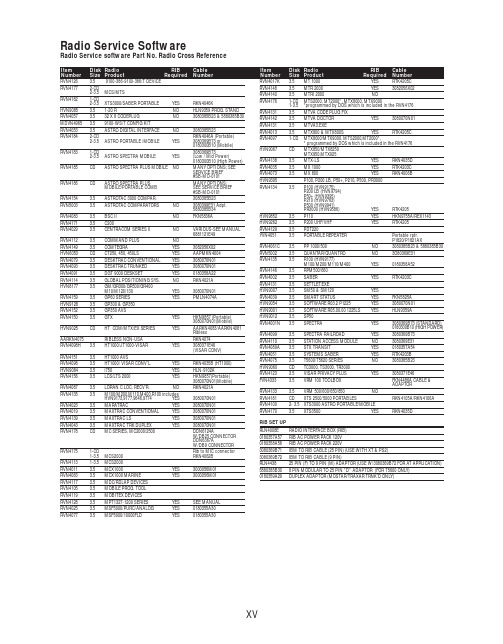
RVN4126 3.59100-386-9100-386/T DEVICERVN41772-CD2-3.5MCS/MTSRVN41821-CD2-3.5XTS3000/SABER PORTABLE YES RKN4046KHVN9085 3.51-20 R NO HLN9359 PROG. STAND RVN4057 3.532 X 8 CODEPLUG NO3080385B23 & 5880385B30 MDVN4965 3.59100-WS/T CONFIG KITRVN4053 3.5ASTRO DIGITAL INTERFACE NO3080385B23RVN41842-CD RKN4046A (Portable) 2-3.5ASTRO PORTABLE /MOBILE YES3080369B73 or0180300B10 (Mobile) RVN41831-CD3080369B732-3.5ASTRO SPECTRA MOBILE YES(Low / Mid Power)0180300B10 (High Power) RVN4185CD ASTRO SPECTRA PLUS MOBILE NO MANY OPTIONS; SEESERVICE BRIEF#SB-MO-0101RVN4186CD ASTRO SPECTRA PLUS MANY OPTIONS;MOBILE/PORTABLE COMB SEE SERVICE BRIEF#SB-MO-0101RVN4154 3.5ASTROTAC 3000 COMPAR.3080385B23RVN5003 3.5ASTROTAC COMPARATORS NO3080399E31 Adpt.5880385B34RVN4083 3.5BSC II NO FKN5836ARVN4171 3.5C200RVN4029 3.5CENTRACOM SERIES II NO VARIOUS-SEE MANUAL6881121E49RVN4112 3.5COMMAND PLUS NORVN4149 3.5COMTEGRA YES3082056X02HVN6053CD CT250, 450, 450LS YES AAPMKN4004RVN4079 3.5DESKTRAC CONVENTIONAL YES3080070N01RVN4093 3.5DESKTRAC TRUNKED YES3080070N01RVN4091 3.5DGT 9000 DESKSET YES0180358A22RVN4114 3.5GLOBAL POSITIONING SYS.NO RKN4021AHVN8177 3.5GM/GR300/GR500/GR400M10/M120/130YES3080070N01RVN4159 3.5GP60 SERIES YES PMLN4074AHVN9128 3.5GP300 & GP350RVN4152 3.5GP350 AVSRVN4150 3.5GTX YES HKN9857 (Portable)3080070N01(Mobile) HVN9025CD HT CDM/MTX/EX SERIES YES AARKN4083/AARKN4081RiblessAARKN4075RIBLESS NON-USA RKN4074RVN4098H 3.5HT1000/JT1000-VISAR YES3080371E46(VISAR CONV)RVN4151 3.5HT1000 AVSRVN4098 3.5HT1000/ VISAR CONV’L.YES RKN4035B (HT1000) HVN9084 3.5i750YES HLN-9102ARVN4156 3.5LCS/LTS 2000YES HKN9857(Portable)3080070N01(Mobile) RVN4087 3.5LORAN C LOC. RECV’R.NO RKN4021ARVN4135 3.5M100/M200,M110,M400,R100 includesHVN9173,9177,9646,9774YES3080070N01RVN4023 3.5MARATRAC YES3080070N01RVN4019 3.5MAXTRAC CONVENTIONAL YES3080070N01RVN4139 3.5MAXTRAC LS YES3080070N01RVN4043 3.5MAXTRAC TRK DUPLEX YES3080070N01RVN4178CD MC SERIES, MC2000/2500DDN6124AW/DB25 CONNECTORDDN6367AW/DB9 CONNECTOR RVN41751-CD Rib to MIC connector 1-3.5MCS2000 RKN4062BRVN41131-3.5MCS2000RVN4011 3.5MCX1000YES3000056M01RVN4063 3.5MCX1000 MARINE YES3000056M01RVN4117 3.5MDC/RDLAP DEVICESRVN4105 3.5MOBILE PROG. TOOLRVN4119 3.5MOBITEX DEVICESRVN4128 3.5MPT1327-1200 SERIES YES SEE MANUALRVN4025 3.5MSF5000/PURC/ANALOG YES0180355A30RVN4077 3.5MSF5000/10000FLD YES0180355A30RVN4017K 3.5MT 1000YES RTK4205CRVN4148 3.5MTR 2000YES3082056X02RVN4140 3.5MTRI 2000NORVN41761-CD MTS2000, MT2000*, MTX8000, MTX90001-3.5*programmed by DOS which is included in the RVN4176RVN4131 3.5MTVA CODE PLUG FIXRVN4142 3.5MTVA DOCTOR YES3080070N01RVN4131 3.5MTVA3.EXERVN4013 3.5MTX800 & MTX800S YES RTK4205CRVN4097 1-CD MTX8000/MTX9000,MTS2000,MT2000*,* programmed by DOS which is included in the RVN4176HVN9067CD MTX850/MTX8250MTX950,MTX925RVN4138 3.5MTX-LS YES RKN4035DRVN4035 3.5MX 1000YES RTK4203CRVN4073 3.5MX 800YES RKN4006BHVN9395 P100, P200 LB, P50+, P210, P500, PR3000RVN4134 3.5P100 (HVN9175)P200 LB (HVN9794)P50+ (HVN9395)P210 (HVN9763)P500 (HVN9941)PR3000 (HVN9586)YES RTK4205HVN9852 3.5P110YES HKN9755A/REX1143 HVN9262 3.5P200 UHF/VHF YES RTK4205RVN4129 3.5PDT220YVN4051 3.5PORTABLE REPEATER Portable rptr.P1820/P1821AXRVN4061C 3.5PP 1000/500NO3080385B23 & 5880385B30 RVN5002 3.5QUANTAR/QUANTRO NO3O80369E31RVN4135 3.5R100 (HVN9177)M100/M200/M110/M400YES0180358A52RVN4146 3.5RPM500/660RVN4002 3.5SABER YES RTK4203CRVN4131 3.5SETTLET.EXEHVN9007 3.5SM50 & SM120YESRVN4039 3.5SMART STATUS YES FKN5825AHVN9054 3.5SOFTWARE R03.2 P1225YES3080070N01HVN9001 3.5SOFTWARE R05.00.00 1225LS YES HLN9359AHVN9012 3.5SP50RVN4001N 3.5SPECTRA YES3080369B73 (STANDARD)0180300B10 (HIGH POWER) RVN4099 3.5SPECTRA RAILROAD YES3080369B73RVN4110 3.5STATION ACCESS MODULE NO3080369E31RVN4089A 3.5STX TRANSIT YES0180357A54RVN4051 3.5SYSTEMS SABER YES RTK4203BRVN4075 3.5T5600/T5620 SERIES NO3080385B23HVN9060CD TC3000, TS3000, TR3000RVN4123 3.5VISAR PRIVACY PLUS YES3080371E46FVN4333 3.5VRM 100 TOOLBOX FKN4486A CABLE &ADAPTORRVN4133 3.5VRM 500/600/650/850NORVN4181CD XTS 2500/5000 PORTABLES RKN4105A/RKN4106A RVN41002- 3.5XTS3000 ASTRO PORTABLE/MOBILERVN4170 3.5XTS3500YES RKN4035DRIB SET UPRLN4008E RADIO INTERFACE BOX (RIB)0180357A57RIB AC POWER PACK 120V0180358A56RIB AC POWER PACK 220V3080369B71IBM TO RIB CABLE (25 PIN) (USE WITH XT & PS2)3080369B72IBM TO RIB CABLE (9 PIN)RLN443825 PIN (F) TO 9 PIN (M) ADAPTOR (USE W/3080369B72 FOR AT APPLICATION) 5880385B308 PIN MODULAR TO 25 PIN ”D” ADAPTOR (FOR T5600 ONLY)0180359A29DUPLEX ADAPTOR (MOSTAR/TRAXAR TRNK’D ONLY)Item Disk Radio RIB Cable Number Size Product Required Number Item Disk Radio RIB Cable Number Size Product Required NumberUtilizing your personal computer, Radio Service Software (RSS)/Customer Programming Software (CPS)/CustomerConfiguration Software (CCS) enables you to add or reprogram features/parameters as your requirements change. RSS/CPS/CCS is compatible with IBM XT, AT, PS/2 models 30, 50, 60 and 80.Requires 640K RAM. DOS 3.1 or later. Consult the RSS users guide for the computer configuration and DOS requirements. (ForHT1000, MT/MTS2000, MTX838/8000/9000, Visar and some newer products —IBM model 386, 4 MEG RAM and DOS 5.0 or higher are recommended.) A Radio Interface Box (RIB) may be required as well as the appropriate cables. The RIB and cables must be ordered separately.Licensing:A license is required before a software (RVN) order is placed. The software license is site specific (customer number and ultimate destination tag). All sites/locations must purchase their own software.Be sure to place subsequent orders using the original customer number and ship-to-tag or other licensed sites; ordering software without a licensed customer number and ultimate tag may result in unnecessary delays. To obtain a no charge license agreement kit, order RPX4719. To place an order in the U.S. call 1-800-422-4210. Outside the U.S., FAX 847-576-3023.Subscription Program:The purchase of Radio ServiceSoftware/Customer Programming/Customer ConfigurationSoftware (RVN & HVN kits) entitles the buyer/subscriber to three years of free upgrades. At the end of these three years, the sub-scriber must purchase the same Radio Service Software kit to receive an additional three years of free upgrades. If the sub-scriber does not elect to purchase the same Radio Service Software kit, no upgrades will be sent. Annually a subscription status report is mailed to inform subscribers of the RSS/CPS/CCS items on our database and their expiration dates.Notes:1)A subscription service is offered on “RVN”-Radio Service Software/Customer Programming/Customer Configuration Software kits only.2)“RVN” software must only be procured through Radio Products and Services Division (RPSD). Software not procured through the RPSD will not be recorded on the subscription database; upgrades will not be mailed.3)Upgrades are mailed to the original buyer (customer number & ultimate tag).4)SP software is available through the radio product groups.The Motorola General Radio Service Software Agreement is now available on Motorola Online. If you need assistance please feel free to submit a “Contact Us” or call 800-422-4210.SMART RIB SET UPRLN1015D SMART RIB0180302E27 AC POWER PACK 120V 2580373E86 AC POWER PACK 220V3080390B49SMARTRIB CABLE (9 PIN (F) TO 9 PIN (M) (USE WITH AT)3080390B48SMARTRIB CABLE (25 PIN (F) TO 9 PIN (M) (USE WITH XT)RLN4488ASMART RIB BATTERY PACKWIRELESS DATA GROUP PRODUTS SOFTWARERVN4126 3.59100-386/9100T DEVICES MDVN4965 3.59100-WS/T CONFIG’TN RVN41173.5MDC/RDLAP DEVICESPAGING PRODUCTS MANUALS6881011B54 3.5ADVISOR6881029B90 3.5ADVISOR ELITE 6881023B20 3.5ADVISOR GOLD 6881020B35 3.5ADVISOR PRO FLX 6881032B30 3.5BR8506881032B30 3.5LS3506881032B30 3.5LS5506881032B30 3.5LS7506881033B10 3.5LS9506881035B20 3.5MINITOR III8262947A15 3.5PAGEWRITER 20008262947A15 3.5PAGEWRITER 2000X 6881028B10 3.5TALKABOUT T3406881029B35 3.5TIMEPORT P7308262947A15 3.5TIMEPORT P930NLN3548BUNIVERSAL INTERFACE KITItem Disk Radio NumberSize Product。
已通过泰尔认证中心产品认证的统一接口手机充电器名录-泰尔

泰尔认证产品认证标志:附件:已通过泰尔认证中心产品认证的统一接口手机充电器名录(按证书编号排序)序号获证产品申请单位生产单位证书编号1 UE05WCP-050YYYSPA(EE16变压器型号UE05WCP-050100SPA-T1,控制芯片:ACT30)东莞市石龙富华电子有限公司东莞市石龙富华电子有限公司030074640257R0L2 UE05WCP-050YYYSPA(EE13变压器型号E04WFP1-050075SPA-T1,控制芯片:ACT30)东莞市石龙富华电子有限公司东莞市石龙富华电子有限公司030074640258R0L3 GXQ-050600移动通信手持机充电器(EE16B变压器和THX202H控制芯片)深圳市高新奇科技股份有限公司深圳市高新奇科技股份有限公司030074640259R0L4 TPC0500700型移动通信手持机充电器(EFD15变压器,1W1689控制芯片)泰尼普拉科技(深圳)有限公司(经销商)依特利电子(深圳)有限公司030074640260R0S5 TC-G90移动通信手持机充电器(EE-16变压器,13003控制芯片)深圳市华锦电子有限公司深圳市华锦电子有限公司030074640284R0M6 YSD-001型移动通信手持机充电器(E16变压器,LNK363PN芯片)宁波奥克斯空调有限公司深圳市伊斯达电子有限公司030074640295R0M7 U5050型移动通信手持机充电器(901.1168变压器,TH2267控制芯片)宁波波导股份有限公司飞煌世亚电业(深圳)有限公司030074640296R0L8 KLC-08USB型移动通信手持机充电器(XQLCT0001变压器,IN60MOSFET控制芯片)深圳康佳通信科技有限公司深圳市华侨城新侨科技有限公司030074640315R0M9 H21115型移动通信手持机旅行充电器(TS003050B01,EE16B,M0S变压器,IN60控制芯片)青岛海尔通信有限公司深圳市腾威电子有限公司030074640316R0M10 C-P06/5V 500mA移动通信手持机充电器(TS009049B01,EE-16联想移动通信科技有限公司深圳市腾威电子有限公司030074640327R0M。
施耐德变频器选型手册

1
选型指导
产品类型
软起动器
通用型变频器
C 应用:
C 应用:
C 应用:
压缩机、泵、风机等 压缩机、泵、风机、 泵、风机等 大惯性机械、传送 装置。
耐德电气从一个优秀的产品和设备供应商逐步成长为整体解决方案提供商。今年,施耐德电气首
次集成其在建筑楼宇、IT、安防、电力及工业过程和设备等五大领域的专业技术和经验,将其高
质量的产品和解决方案融合在一个统一的架构下,通过标准的界面为各行业客户提供一个开放、
透明、节能、高效的 运营成本。
能效管理平台,为企业客户节省高达30%的投资成本和
电机功率 变频器
输出频率
4...400 kW –
控制类型 异步电机 可配置的电压斜坡 控制
同步电机 –
瞬时过转矩
–
功能
功能数量
预置多段速度的数目
I/O 的数目 模拟输入
逻辑输入
模拟输出
逻辑输出
继电器输出
通讯
集成通讯协议
可选配件
36 – 1 PTC 探头 3 – – 2 Modbus –
卡 (可选配件)
2
复杂、大功率变频器
C 应用:
泵、多泵、风机、压缩机 风机、泵、压缩机,各种标准 转矩应用
C 应用:
传送带、搅拌机、挤出机、 起重等
C 应用:
电力、采矿和选矿、石油和天 然气、水处理等中压系统中的 风机、泵、压缩机等
C 应用:
起重应用、下坡输送带、绞盘、自动扶 梯、高动态驱动器、泵/涡轮组合等
MT8852B中文说明书

MT8850A / MT8852A / MT8852B 操作手册软件版本3.00以上适用蓝牙MT8850A / MT8852A /MT8852B蓝牙测试组操作手册供MT8850A、MT8852A、MT8852B 软件版本3.00及以上使用創作者: Anritsu Ltd,EMD,Stevenage,U.K.P/N: 13000-00109修訂: HCREATED August 2004COPYRIGHT 2004ANRITSU本手冊之重要通知使用者應了解本手冊為最初草稿版本,本手冊中某些章節的資訊在手冊付印時尚無法取得。
本手冊提供以下軟體版本之操作與功能細節:MT8850A: 3.00MT8852A: 3.00MT8552B: 4.00本手冊中所記載之某些功能於先前版本之軟體上可能無法提供。
產品保證Anritsu 公司的產品係為依據本保證書的內容,提供本產品其製作材質和作工品質缺陷,自產品出貨起1 年的產品保證。
Anritsu 提供的產品保證內容,係提供產品保證期間內,包括經證明產品瑕疵,其相關產品修護或更換服務。
產品用戶應先行支付運費,將有瑕疵的產品送回到Anritsu,以進行產品保證品質的修護服務。
本產品保證服務只限於原有的產品購買人,Anritsu 對於其後續用戶的使用產品瑕疵,不提供任何產品保證的擔保服務。
產品有限保證責任聲明上述的產品保證責任,不適用於Anritsu 的裝置接頭,係因為正常使用而損害者。
同樣地,本產品保證服務不適用於因為購買人不當的使用、未經授權的裝置修改或使用錯誤,或未依據產品的使用環境規範,而造成產品損害者。
本產品未再明文指示和暗示提供任何其他的品質保證責任,本產品修護保證服務,係僅限於本產品的原有購買人,所獨屬專有的權利。
註冊商標聲明藍芽註冊商標係由藍芽技術聯盟(SIG)所有,V Connector 與K Connector 係為Anritsu有限公司之註冊商標,Adobe Acrobat 與Acrobat Reader 係為Adobe 系統企業之商標。
- 1、下载文档前请自行甄别文档内容的完整性,平台不提供额外的编辑、内容补充、找答案等附加服务。
- 2、"仅部分预览"的文档,不可在线预览部分如存在完整性等问题,可反馈申请退款(可完整预览的文档不适用该条件!)。
- 3、如文档侵犯您的权益,请联系客服反馈,我们会尽快为您处理(人工客服工作时间:9:00-18:30)。
T 822 om-11PROVISIONAL METHOD – 1984 OFFICIAL TEST METHOD – 1989REVISED – 1993 REVISED – 2002 REVISED – 2007 REVISED – 2011©2011 TAPPIThe information and data contained in this document were prepared by a technical committee of the Association. The committee and the Association assume no liability or responsibility in connection with the use of such information or data, including but not limited to any liability under patent, copyright, or trade secret laws. The user is responsible for determining that this document is the most recent edition published.Approved by the Standard Specific Interest Group for this Test MethodTAPPICAUTION:This Test Method may include safety precautions which are believed to be appropriate at the time of publication of the method. The intent of these is to alert the user of the method to safety issues related to such use. The user is responsible for determining that the safety precautions are complete and are appropriate to their use of the method, and for ensuring that suitable safety practices have not changed since publication of the method. This method may require the use, disposal, or both, of chemicals which may present serious health hazards to humans. Procedures for the handling of such substances are set forth on Material Safety Data Sheets which must be developed by all manufacturers and importers of potentially hazardous chemicals and maintained by all distributors of potentially hazardous chemicals. Prior to the use of this method, the user must determine whether any of the chemicals to be used or disposed of are potentially hazardous and, if so, must follow strictly the procedures specified by both the manufacturer, as well as local, state, and federal authorities for safe use and disposal of these chemicals.Ring crush of paperboard (rigid support method)1. Scope1.1 The ring crush test correlates with edgewise compression strength of paperboard (1,2). 1.2 This method is intended for paperboard between 0.28 mm (0.011 in.) and 0.61 mm (0.024 in.) thick. It may be used with less reliability for paperboard as thin as 0.18 mm (0.007 in.) and as thick as 0.76 mm (0.030 in.).NOTE 1:Caution should be used when testing linerboard less or greater than the specified thickness as the results may be less reliable. For papers thinner than 0.28 mm (0.011 in.), test values may result from a combination of both buckling failure and pure compression. For papers thicker than specified, strain within the sample arising from bending the specimens into a cylinder may impact test results (3,4).2. SignificanceThe edgewise compression strength of corrugated board is the principal element in determining the dynamic compression strength of the container made from that board. Fiberboard shipping containers are frequently subjected to loads which are resisted by compression strength, making this property an important measure of the performance characteristics of corrugated board, and useful in controlling the manufacturing process and in measuring the quality of the finished product. Since edgewise compression strength can be estimated by a summation of the ring crush strengths of the liners and medium, this method is useful for the corrugated boxmaker. 3. SummaryA compression force is exerted on a specimen held in ring form in a special sample holder and placed between two platens of a compression machine, by causing the driven platen to approach the rigid platen at a uniform speed until the specimen collapses.--`,,```,,,,````-`-`,,`,,`,`,,`---4. Apparatus4.1 Compression testing machine1 meeting the following requirements:4.1.1 Rigid Support Compression Tester. Two platens, one rigidly supported and the other driven. Each platenshall have a working area of approximately 100 cm2 (16 in.2). The platens are to have not more than 0.050 mm (0.002 in.) lateral relative movement, and the rigidly supported platen not more than 0.150 mm (0.006 in.) movement, perpendicular to the surface, within a load range of 0 to 2225 N (0-500 lbf). Within the specimen contact area, each platen shall be flat within 0.0025 mm (0.0001 in.) of the mean platen surface, and the platens shall remain parallel to each other within 1 part in 2000 throughout the test.4.1.2 A means for moving the driven platen to achieve an initial platen separation of at least 60 mm (2.36 in.).Within a range of platen separation of 0 to 60 mm (0 to 2.36 in.) and within a load range of 0 to 2225 N (0 to 500 lbf), the nominal speed of the driven platen shall be controllable at 12.5 mm ± 0.2 mm (0.50 in. ± 0.008 in.) per minute.NOTE 2:For convenience, the test machine should be capable of rapid return and automatic, settable positioning.4.1.3 A capacity of at least 2225 N (500 lbf).4.1.4 A means of measuring and indicating the maximum load sustained by the test specimen within 2.2 N(0.50 lbf) or 1% error, which ever is greater.4.1.5 An indicating mechanism that can be checked accurately with dead-weight load, load cell, or provingring. The accuracy required is 0.5% or 2.2 N (0.5 lbf), whichever is greater.4.2 Specimen holder, having the following characteristics:4.2.1 The specimen holder will be composed of a circular block having an annular square cut groove, 6.4 ±0.25 mm (0.25 ± 0.01 in.) deep and 49.3 ± 0.035 mm (1.940 ± 0.001 in.) outside diameter. The bottom of the annulargroove is required to be parallel with the base of the block ± 0.01 mm (0.0004 in.), with the sides of the groove at right angles with the base of the block. A branch groove tangent to the annular groove, of the same depth and extending to the edge of the block, is provided to insert the specimen and is not wider than 1.27 mm (0.050 in.) at its entrance to the annular groove.4.2.2 The center “island” created by the annular groove is removable and replaceable with disks of differentdiameters so that the width of the groove may be adjusted to be at least 150% but not more than 175% of the nominal caliper of the specimen being tested. Each disk has a central hole to fit a receiving pin central to the annular groove and is free to turn as the specimen is inserted through the branch groove.4.2.3 Scribe or otherwise mark one point on the perimeter of the annular groove at some distance, at least12.5 mm (0.5 in.) away from the branch groove. This point will serve as the mark for the ends of the test specimen.4.3 Precision die cutter, capable of accurately cutting the test specimens with clean parallel edges.5. SamplingSamples should be selected and gathered in accordance with TAPPI T 400 “Sampling and Accepting a Single Lot of Paper, Paperboard, Containerboard, or Related Products.”6. ConditioningDue to possible dimensional changes and the impact of moisture on strength properties, precondition and condition samples prior to cutting test specimens in an atmosphere in accordance with TAPPI T 402 “Standard Conditioning and Testing Atmospheres for Paper, Board, Pulp, Handsheets, and Related Products”7. Preparation of test specimens7.1 Carefully die-cut test specimens with the felt side (top side) toward the male portion of the die 12.700 +0.000 - 0.025 mm (0.500 + 0.000 - 0.001 in.) wide, 152.4 + 0.000 - 0.200 mm (6.00 + 0.000 – 0.008 in.) long. Cut so thatthe long dimension is parallel with the machine direction of the board for CD specimens and the long dimension is --`,,```,,,,````-`-`,,`,,`,`,,`---1Names of suppliers of testing equipment and materials for this method may be found on the Test Equipment Suppliers list, available as part of the CD or printed set of Standards, or on the TAPPI website general Standards page.perpendicular to the machine direction of the board for the MD specimens (if MD tests are performed). Accurate determination of the machine and cross directions is critical. In cutting the specimens take care to ensure that the long edges are parallel, such that the widths at opposite ends are within 0.015 mm (0.0006 in.) of each other.NOTE 3:Die cutting of single sheets is the proper way to cut the test specimens, meet the requirements of this section, and give test results within the precision stated.7.2 Test 10 specimens per sample in each direction of interest.7.3 Periodically inspect a cut specimen under an appropriate magnification to check for proper dimensions (7.1) and to ensure that cuts are clean and sharp. Any damage to the edges may indicate the die-cutter should be checked for sharpness, nicks, or burrs.8. Procedure8.1 Wear rubber, plastic, or disposable lint-free cotton gloves throughout the entire test procedure.NOTE 4:Contaminants on hands, especially moisture, may have an adverse effect on test results.8.2 Determine the average thickness (caliper) of the sample to be tested in order to select the proper disk insert (4.2.2).8.3 Wearing gloves, carefully insert the test specimen into the specimen holder. Locate the ends so that they are at the scribed mark (4.2.3) as not to coincide with the branch groove. Place the specimens in the holder so that half are tested with the felt side (top side for twin wire formed sheets) facing inward and half with the felt side facing outward.--`,,```,,,,````-`-`,,`,,`,`,,`---NOTE 5:If the specimen buckles on insertion or the disk rises allowing the specimen to get beneath the disk during the compression test, the test results may be low. Discard these test results and test additional samples.8.4 Place the holder with the test specimen on the center of the lower platen of the compression machine. It is desirable to fix stop blocks on the lower platen to ensure proper placing of the holder, but the holder can always be centered if the platen is marked or scribed. Position the holder so that the meeting specimen ends are always in the same position, i.e., directly in front of the operator.NOTE 6:If the load cell supports the lower platen, the sample holder must be centered on the lower platen when checking and/or setting the zero load level.8.5 Apply a load to the specimen by activating the driven platen at a speed of 12.5 mm/min (0.50 in/min) until a maximum force is sustained. Immediately after reaching the maximum, the specimen will fail in the area projecting above the holder. This may not be visually observed when using equipment that returns rapidly after reachinga peak load. Record this maximum load value.8.6 For 152.4 mm (6.0 in.) test specimens, to convert test values to kilonewtons per meter, multiply the readings in pounds force (lbf) by 0.0292. Similarly, multiply readings in kilograms force (kgf) by 0.0644, and multiply readings in newtons by 0.00656.8.7 Collect the test specimens and determine their moisture content as a composite reading according to TAPPI T 412 “Moisture in Paper,” if the samples have not been conditioned to TAPPI standard conditions as outlined in T 402 “Standard Conditioning and Testing Atmospheres for Paper, Board, Pulp Handsheets, and Related Product.”NOTE 7:The ring crush test is extremely sensitive to the moisture content of the paperboard under test. Since paperboard does not always condition to identical moisture contents, knowledge of the latter will sometimes explain differences in between-laboratory results.9. Report9.1 Report the averages of the CD and MD (if performed) test results separately. Report the force per unit specimen length required to crush the specimens and the standard deviation, in kilonewtons per meter (or in pounds force for 6 in. specimens) to three significant figures.9.2 Include the total number of specimens tested.9.3 Report the moisture content of the specimens tested if the samples have not been conditioned to TAPPI standard conditions following TAPPI T 402 “Standard conditioning and testing atmospheres for paper, board, pulp handsheets, and related products.”10. Precision 10.1 Repeatability = 4% 10.2 Reproducibility = 17%Repeatability and reproducibility are estimates of the maximum difference (at 95% confidence) that should be expected when comparing test results for materials similar to those described in the chart under similar test conditions to those described below. These estimates may not be valid for different materials and testing conditions. 10.3 As the estimates of repeatability and reproducibility are not proportional (the ratio of variation to average test result is not consistent between different grades), likely because the variation has both a fixed component and a basis weight-dependent component (2), users are encouraged to use the chart below to identify precision estimates for each grade.Material AverageRepeatabilityr and %rReproducibility R and%RLabs Included26# medium 40.4 2.14 5.2% 9.09 22.5% ~ 20 35# linerboard 75.4 3.50 4.6% 12.58 16.6% ~ 60 42# linerboard 106.9 3.41 3.2% 16.13 15.2% ~ 60 69# linerboard161.14.76 3.0%21.89 13.6%~ 60Data in the table above are listed in lbf for 6-in specimen10.4 The estimates of repeatability and reproducibility listed in the table above are based on data from the Collaborative Testing Services Inc. (CTS) Containerboard Interlaboratory Program using testing conducted in 2006. The data included either 12 weekly rounds of testing, for 36lb linerboard and 69lb linerboard, or 24 weekly rounds of testing, 26lb medium and 42lb linerboard. The precision estimates are based on 10 determinations per test result and 1 test result per lab for each round of testing. For each weekly round, between 57 and 68 (approximately 60) laboratories are included in the calculation of the precision estimates for linerboard and between 20 and 25 (approximately 20) laboratories are included in the calculation of precision estimates for corrugating medium. Only laboratories that reported using rigid-platen type instruments and TAPPI standard conditioning atmospheres are included in the calculations. 10.5 Additional Information. The precision statement above (10.1 through 10.4) replaced information derived from an interlaboratory study conducted in 1999. The current repeatability estimates are approximately 50% lower than those derived from the 1999 trial. The 1999 trial used the average of 3 results to calculate repeatability, whereas this trial uses single results from a large number of laboratories and multiple rounds of testing. The estimates for reproducibility are not significantly different. Additionally the 1999 trial used an alternate specimen cutting procedure to investigate possible differences when cutting with bottom (felt) side down v. bottom side up. The results showed no difference for most samples, however ring crush results were higher for heavy weight linerboard using the alternate specimen cutting method. The trial showed a 3.5-lbf/6-in. difference for 69-lb linerboard and a 14.5-lbf/6-in. difference for 90-lb linerboard.11. KeywordsPaperboard, Corrugated boards, Fiberboards, Ring crush tests, Compression tests, Edge crush resistance12. Additional Information12.1 Effective date of issue: September 27, 2011.--`,,```,,,,````-`-`,,`,,`,`,,`---12.2 Related method: TAPPI T 818 “Ring Crush of Paperboard” uses a deflecting beam tester operating undera loading rate of 111 N/S (25 lbf/s) but in other respects is similar. Test results from T 818 may be different from the test results obtained with method T 822.12.3 Related method: TAPPI T 826 “Short Span Compression Strength of Paperboard.” Test results from T 826 will be different from the test results obtained with method T 822 and are not expected to be proportional (2).12.4 Related method: ISO 12192 “Paper and board – Compressive strength – Ring crush method.”12.5 The 2011 revision included several editorial changes.and added several references.Literature cited1. Koning, J.W., “A short column crush test of corrugated paperboard,” Tappi47 (3):134 (1964).2. Frank, B., “Ring crush and short span compression for predicting edgewise compressive strength,” Tappi Journal2 (11): 12 (2003)3. “Effect of specimen dimensions on edgewise compression tests of linerboard and corrugating medium,” Parts 1and 2, Testing Compression Reports 82 and 83, Institute of Paper Chemistry, Project 1108-4, March 23, 1966.4. Fellers, C., and Donner, B. C., “Edgewise compression strength of paper,” in Handbook of Physical Testing ofPaper, Vol. 1, Chapter 9, Marcel Dekker Inc., 2nd edition.ReferencesSmith, J.H., “A Discussion of the Ring Crush Test,” Tappi, Vol. 42 (1959).Travers, R., “Improving the Reliability of the Ring Crush Test,” Appita, Nov. 1976.Koning, J.W., Kuenzl, E.W., Mood, R.C., & Godshall, W.D., “Improving the Comparability of Paperboard Test ResultsUsing Flexible and Rigid Type Testing Machines,” Tappi, May 1972.Dahl, Carl B., Jr. “Limited Range of Ring Crush Test,” Tappi Journal68 (10): 108-109, October 1985.Frank, B., “Revisiting Paper Strength Measurements for Estimating Combined Board Strength ,” Tappi Journal 6 (9): 10 (2007)Whitsitt, W.J., Institute of Paper Chemistry (IPC) Report, “Relationships Between Elastic Properties and End-Use Performance,” Project 2695-23, January 30, 1985, /1853/701Batelka, J. J., “The Comparative Response of Right Crush Test and STFI Short Span Crush Test to Paper Mill Process Variable Changes,” Corrugating International 2 (4): 163 (2000)Replogle, J.W.., “Ring Crush vs. STFI for Testing Compression”, Corrugating International 3 (3):163 (2001) Allan, R., “To Ring Crush or Not To Ring Crush”, Appita Journal, 56 (2):88, March 2003Your comments and suggestions on this procedure are earnestly requested and should be sent to the TAPPI Standards Department.g --` , , ` ` ` , , , , ` ` ` ` -` -` , , ` , , ` , ` , , ` ---。