VLS、VLC-003004系列VALCOM称重传感器
称重传感器suncells
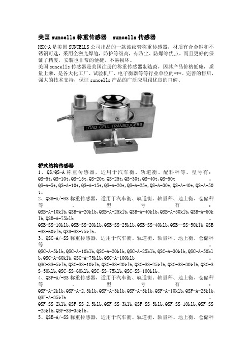
美国suncells称重传感器suncells传感器HSX-A是美国SUNCELLS公司出品的一款波纹管称重传感器,材质有合金钢和不锈钢可选,采用全激光焊缝,防护等级高,有防尘、防爆等优点。
而且更好的保证了精度,安装也非常的便捷,不易损坏。
美国suncells传感器是美国注册的称重传感器制造商,因其产品价格低廉,质量上乘,是各大化工厂、试验机厂、电子衡器等等行业单位的***。
完善的售后,强大的技术支持,保证suncells产品的广泛应用跟优良的口碑、桥式结构传感器1、QS/QS-A称重传感器,适用于汽车衡、轨道衡、配料秤等。
型号有:QS-5t,QS-10t,QS-15t,QS-20t,QS-25t,QS-30t,QS-40t,QS-50t。
QS-A-5t,QS-A-10t,QS-A-15t,QS-A-20t,QS-A-25t,QS-A-30t,QS-A-40t,QS-A-50 t。
2、QSB-A/-SS称重传感器,适用于汽车衡、轨道衡、轴量秤、地上衡、仓储秤等。
型号有:QSB-A-10klb,QSB-A-20klb,QSB-A-25klb,QSB-A-40klb,QSB-A-50klb,QSB-A-60k lb,QSB-A-75klb。
QSB-SS-10klb,QSB-SS-20klb,QSB-SS-25klb,QSB-SS-40klb,QSB--SS-50klb,QSB -SS-60klb,QSB-SS-75klb。
3、QSC-A/-SS称重传感器,适用于汽车衡、轨道衡、轴量秤、地上衡、仓储秤等。
QSC-A-5klb,QSC-A-10klb,QSC-A-20klb,QSC-A-25klb,QSC-A-30klb,QSC-A-50kl b,QSC-A-60klb,QSC-A-75klb,QSC-A-100klb。
QSC-SS-5klb,QSC-SS-10klb,QSC-SS-20klb,QSC-SS-25klb,QSC-SS-30klb,QSC-S S-50klb,QSC-SS-60klb,QSC-SS-75klb,QSC-SS-100klb。
PT称重传感器

PT称重传感器广州南创蔡工PT称重传感器已经服务超过30年衡器行业,前身为精密传感器,该公司在2002年改变其名称为PT,现已成为高品质的称重计量设备的代名词。
PT称重传感器产品介绍:PT称重传感器应用:●混合尺度●材料测试●杠杆转换●吊秤●料斗称重PT称重传感器特点:●兼容国际标准定价●拉伸,压缩及悬移质应用●容量大覆盖●3年质保●化学镀镍工具钢为IP65●ISO 9001认证的生产设施PT称重传感器尺寸大小:产品名称:PT称重传感器产品型号:PT称重传感器ST产品说明:新西兰PT称重传感器新西兰PT称重传感器相关型号:PT4000-20kg PT4000-50kg PT4000-100kg PT4000-200kg PT4000-500kgPT4000-1000kg PT4000-2000kg PT4000-3000kg PT4000-5000kgPT4000-50lb PT4000-100lb PT4000-150lb PT4000-200lb PT4000-200lbPT4000-250lb PT4000-300lb PT4000-500lb PT4000-750lb PT4000-1000lbPT4000-1500lb PT4000-2000lb PT4000-2500lb PT4000-3000lb PT4000-5000lb PT4000-10000lb PT4000-20000lb (PST 20) 50kg(PST 50) 100kg(PST 100) 250kg(PST 250) 500kg(PST 500) 1000kg(PST 1000) AST-100 100kgAST-250 250kg AST-500 500kg AST-1000 1000kgPT称重传感器规格参数:PT称重传感器配件参数:。
奥美晨曦系列微波传感器说明书

OS100 SERIES Mini-Infrared Transmitter e-mail:**************For latest product manuals: Shop online at User’s G ui d e***********************Servicing North America:U.S.A. Omega Engineering, Inc.Headquarters: Toll-Free: 1-800-826-6342 (USA & Canada only)Customer Service: 1-800-622-2378 (USA & Canada only)Engineering Service: 1-800-872-9436 (USA & Canada only)Tel: (203) 359-1660 Fax: (203) 359-7700e-mail:**************For Other Locations Visit /worldwideThe information contained in this document is believed to be correct, but OMEGA accepts no liability for any errors it contains, and reserves the right to alter specifications without notice.Table of ContentsSection ...................................................................PageSafety Warnings and IEC Symbols (iii)Caution and Safety Information (iii)Section 1 Introduction ....................................................................1-1Section 2Installation ......................................................................1-12.1 Unpacking and Inspection ......................................1-12.2 Electrical Connection ..............................................2-1Section 3Operation ........................................................................3-13.1 Main Board ................................................................3-13.2 Ambient Temperature ..............................................3-23.3 Atmospheric Quality ................................................3-33.4 Measuring Temperature ..........................................3-33.5 Alarm Setting ............................................................3-43.6 Adding Extension Cable...........................................3-4Section 4 Laser Sight Accessory ...................................................4-14.1 Warning and Cautions .............................................4-14.2 Operating the Laser Sight Accessory .....................4-1Section 5 Specifications .................................................................5-15.1 General .......................................................................5-15.2 Laser Sight Accessory (OS100-LS) ..........................5-2Section 6Emissivity Table .............................................................6-1iTable of FiguresFigure Description Page2-1Power Supply & Analog Output Connections ..........2-12-2 Alarm Output Connection ............................................2-13-1 Main PC Board ...............................................................3-23-2 Sensor..............................................................3-2Housing3-3 Optical Field of View .....................................................3-43-4Setting the Temperature Engineering Unit..................3-43-5Mounting Bracket OS100-MB .......................................3-53-6Water Cooling Jacket, OS100-WC ................................3-53-7Typical Water Cool Jacket Assembly ...........................3-53-8Air Purge Collar, OS100-AP..........................................3-63-9DIN Rail Mounting Adapter, OS100-DR ....................3-63-10NEMA-4 Aluminum Enclosure ....................................3-64-1Laser Sighting Accessory, OS100-LS ............................4-24-2Laser Warning Label ......................................................4-2iiSafety Warnings and IEC SymbolsThis device is marked with international safety and hazard symbols in accordance with IEC 1010. It is important to read and follow all precautions and instructions in this manual before operating or commissioning this device as it contains important information relating to safety and EMC. Failure to follow all safety precautions may result in injury and or damage to your calibrator. IEC symbols DescriptionCaution and Safety Information• If the equipment is used in a manner not specified in this manual, the protection provided by the equipment may be impaired.• The installation category is one (1).• There are no user replaceable fuses in this product• The output terminals of this product are for use with equipment (digital meters, chart recorders, etc,) which have no accessible five parts. Such equipment should comply with all the applicable safety requirements.• Do not operate the equipment in flammable or explosive environments.• All connections to the thermometer should be made via a shielded cable, 24 AWG stranded wire with the following ratings: 300V , 105°C (221°F), PVC insulation.• Power must be disconnected before making any electrical connections.• The power supply used to power the thermometer should be VDE or UL approved with the following ratings: 12 to 24vdc @150mA with overload protection of 500mA.iiiCaution, refer to accompanying documentsDirect Current Laser SymbolFrame or ChassisNOTES: ivSection 1 - IntroductionThe low cost OS101 mini-infrared transmitter provides non-contacttemperature measurement for industrial applications. The unit measures atemperature range of -18 to 538°C (0-1000°F) and provides a linear analogoutput of either 4-20 mA, 0-5 VDC, K type TC, 1 mV/°C, or 1 mV/°F.The new OS102 mini-infrared transmitter has all the functions of OS101plus a built-in LED display that shows the measured temperature indegrees F or degrees C which is switchable in the field.The miniature sensor head design 2.5 cm dia. x 6.3 cm Length (1" x 2.5") isideal for measuring temperature in confined, and hard to reach places.The aluminum sensor head as well as the rugged electronic housing (Diecast Aluminum) are NEMA-4 rated.The sensor head is connected to the electronic housing via a 1.82 m (6 feet)shielded cable as standard. The unit provides field adjustable alarmoutput.Section 2 - Installation2.1UnpackingRemove the packing list and verify that you have received all yourequipment. If you have any questions about the shipment, please callCustomer Service at:1-800-622-2378 or 203-359-1660. We can also be reached on the internet:e-mail:**************When you receive the shipment, inspect the container and equipment forany signs of damage. Note any evidence of rough handling in transit.inspection. After examination and removing contents, save packing material and carton in theevent reshipment is necessary.The following items are supplied in the box:• The infrared transmitter including the sensor head and the 1.82 m(6 feet) shielded cable• User's Manual• Mounting Nut1-1The following describes the ordering information:OS102 or OS101 - MA- *,**, where The following optional accessories are available:Here are the Features of OS101 and OS102 infrared transmitters:2.2Electrical Connection Sensor Head Cable - The Sensor head is pre-wired to a 1.8 m (6 feet)shielded cable. Plug & lock-in the male connector to the mating female connector on the aluminum housing.Power & Output Connection - Open the cover of the main aluminum housing. Slide the cable through the strain relief and connect the wires to the terminal block on the board as shown in Fig. 2-1. For Alarm output connection, refer to Fig. 2-2.2-1MA - 4/20 mA output V1 - 0 to 5 VDC output K - Thermocouple output, K type MV - Millivolt output C - 1 mV/°C output F - 1 mV/°F output HT- High temperature sensor head3-1Figure 2-2. Alarm Output Connection Section 3 - Operation3-1Main BoardThe Main Board is shown in Fig. 3-1. Here are the important components on the board:(1) - Terminal Block for Power & Output connections(2) - Single Turn Potentiometer to adjust Emissivity in tenths (0.x_)(3) - Single Turn Potentiometer to adjust Emissivity in hundreds (0._x)(4) -Slide switch to select between real time (Normal Operation) and alarm set point(5) - Alarm set point adjust, P4(6) - Sensor Head connection(7) - Input Zero adjust, P3(8) - Input Span adjust, P2(9) - Output Zero adjust, P5(10) - Output Span adjust, P6Figure 3-1. Main PC Board3.2Ambient TemperatureThe Sensing head can operate in an ambient temperature of 0 to 70°C (32to 158°F). The Sensing head in the high temperature model (-HT) can operate in an ambient temperature of 0 to 85°C (32 to 185°F) without any cooling required. The Sensing head can operate up to 200°C (392°F) using the water cool jacket accessory OS100-WC (See Fig. 3-6).There is a warm up period of 3 minutes after power up. After the warm up period, temperature measurement can be made.When the ambient temperature around the sensor head changes abruptly,the sensor head goes through thermal shock. It takes a certain amount of time for the sensor head to stabilize to the new ambient temperature. For example, it takes about 30 minutes for the sensor head to stabilize going from 25°C to 50°C (77 to 122°F) ambient temperature.The sensor head dimensions are shown in Fig. 3-2.Figure 3-2. Sensor Housing3-23-33.3Atmospheric QualityEnvironments with smoke, dust, and fumes dirty up the optical lens, and cause erroneous temperature readings. To keep the surface of the optical lens clean, the air purge collar accessory is recommended, OS100-AP , See Fig. 3-7.3.4Measuring TemperatureBefore starting to measure temperature, make sure that the following check list is met:ߜ The power and analog output connections are made (Fig. 2-1).ߜThe sensor head is connected to the main unit.ߜThe slide switch (SW1) on the main board is set to real time (Fig. 3-1).ߜThe target is larger than the optical field of view of the sensor head (Fig. 3-3).ߜThe emissivity adjustment on the main board is set properly (Fig. 3-1).ߜThe output load is within the product specification.On OS102 transmitters, follow these additional steps:ߜ The temperature display is set to °F or °C (Fig. 3-4)ߜ For 4-20mA output models, make sure an output load is added, ie. 250ohms.Figure 3-3. Optical Field Of ViewFigure 3-4. Setting the Temperature Engineering Unit3.5Alarm SettingThe unit provides 0-100% alarm set point adjustment. Here is an exampleof an alarm setting.• An OS101-MA(4/20 mA output), the alarm is to be set at 400°Ftemperature.• Connect the alarm output as shown in Fig. 2-2.• Set the slide switch (SW1) on the main board to the Alarm position.• Measure the analog output, and set the Potentiometer P4 until theoutput reads 10.4 mA which is 40% (400°F) of the temperature range.40 x (20-4)[10.4mA=+ 4]100• Set the slide switch (SW1) back to the Real Time position.• If the temperature reading is below the alarm set point, the alarmoutput stays high, otherwise it goes low.On the OS102, you can set the alarm set point directly based on thetemperature display.3.6Adding Extension CableYou can add extension cable between the Sensor Head and the mainelectronic housing up to 15.2 m (50 feet). After adding the extension cable,the Zero input potentiometer, P3 may be re-adjusted. (See Fig. 3-1, forproper analog output reading)The following figures show the mounting bracket (OS100-MB), Watercooling jacket (OS100-WC), Air purge collar (OS100-AP), DIN RailMounting adapter (OS-100-DR), and the main aluminum enclosure. TheDIN Rail Mounting adapter (OS100-DR) is mounted to the bottom of themain aluminum enclosure using two 4-40 screws.A typical water cool jacket assembly is shown in Fig. 3-7, on the following page.1. Mounting Nut2. Mounting Bracket3. Water Cool Jacket4. Sensor Head3-4Figure 3-5. Mounting Bracket OS100-MBFigure 3-6. Water Cooling Jacket, OS100-WCFigure 3-7. Typical Water Cool Jacket Assembly3-5Figure 3-8. Air Purge Collar, OS100-APFigure 3-9. DIN Rail Mounting Adapter, OS-100-DRFigure 3-10. NEMA-4 Aluminum Enclosure3-6Section 4 - Laser Sight Accessory4.1Warning and Cautionsbelow:•Use of controls or adjustments or performance of procedures other than those specified here may result in hazardous radiation exposure.• Do not look at the laser beam coming out of the lens or view directly with optical instruments - eye damage can result.• Use extreme caution when operation the laser sight accessory • Never point the laser accessory at a person • Keep out of the reach of all children4.2Operating the Laser Sight AccessoryThe laser sight accessory screws onto the front of the sensor head. This accessory is only used for alignment of the sensor head to the target area.After the alignment process, the accessory has to be removed from the front of the sensor head before temperature measurement.The laser sight accessory is powered from a small compact battery pack (included with the accessory). Connect the battery pack to the accessory using the cable provided. Aim at the target, and turn on the battery power using the slide switch on the battery pack. Adjust the sensor head position so that the laser beam points to the center of the target area. Turn off the battery pack, and remove the laser sighting accessory from the sensor head. See Fig. 4-1 for reference.4-14-2Figure 4-2. Laser Warning LabelSection 5 - Specifications5.1 - GeneralTemperature Range-18 to 538°C (0 to 1000°F)Accuracy @ 22°C (72°F)±2% of Rdg. or 2.2°C (4°F) whichever is ambient temperature & greateremissivity of 0.95 or greaterOptical Field of View6:1 (Distance/Spot Size)Repeatability±1% of Rdg.Spectral Response 5 to 14 micronsResponse Time150 msec (0 to 63% of final value)Emissivity Range0.1 to 0.99, adjustableOperating Ambient TemperatureMain Transmitter0 to 50°C (32 to 122°F)Sensor Head0 to 70°C (32 to 158°F)Sensor Head (-HT Model)0 to 85°C (32 to 185°F)Sensor Head with OS100-WC(Water Cooling Jacket)0 to 200°C (32 to 392°F)Operating Relative Humidity Less than 95% RH, non-condensingWater Flow Rate for OS100-WC0.25 GPM, room temperatureThermal Shock About 30 minutes for 25°Cabrupt ambient temperature change Warm Up Period 3 minutesAir Flow Rate for OS100-AP 1 CFM (0.5 Liters/sec.)Power12 to 24 VDC @ 100 mAAnalog OutputsMV-F 1 mV/°FMV-C 1 mV/°CK K Type TC - OS101 onlyMA 4 to 20 mAV10 to 5 VDCOutput Load requirementsMin. Load (0 to 5VDC) 1 K-OhmsMax. Load (4 to 20 mA)(Supply Power - 4 )/20 mATransmitter Housing NEMA-4 & IP65, Die Cast AluminumSensor Head Housing NEMA-4 , AluminumAlarm Output Open Drain, 100 mAAlarm Set Point0 to 100% , Adjustable via P4Alarm Deadband14°C (25°F)5-15-25.1 - General Con’t.DimensionsSensor Head25.4 OD. x 63.5 mm L(1" OD. x 2.5" L)Main Housing, OS10165.5 W x 30.5 H x 115.3 mm L(2.58" W x 1.2" H x 4.54" L)Main Housing, OS10265.5 W x 55.9 H x 115.3 mm L(2.58" W x 2.2" H x 4.54" L)Weight 272 g (0.6 lb)5.2Laser Sight Accessory (OS100-LS)Wavelength (Color)630 - 670 nm (Red)Operating Distance (Laser Dot)Up to 9.1 m (30 ft.)Max. Output Optical Power Less than 1 mW at 22°F ambienttemperature.European Classification Class 2, EN60825-1/11.2001Maximum Operating current45 mA at 3 VDCFDA Classification Complies with 21 CFR 1040.10,Class II Laser ProductBeam Diameter 5 mmBeam Divergence< 2 mradOperating Temperature0 to 50°C (32 to 122°F)Operating Relative Humidity Less than 95% RH, non-condensingPower Switch ON / OFF , Slide switch on the BatteryPackPower Indicator Red LEDPower Battery Pack, 3 VDC (Consists of two 1.5VDC AA size Lithium Batteries) Laser Warning Label Located on the head sight circumferenceIdentification Label Located on the head sight circumferenceDimensions38 DIA x 50.8 mm L(1.5" DIA x 2" L)Section 6 - Emissivity Table6-1Material Emissivity (ε)Aluminum – pure highly polished plate . . . . . . . . . . . . . . . . . . . . . . . . 0.04 to 0.06Aluminum – heavily oxidized . . . . . . . . . . . . . . . . . . . . . . . . . . . . . . . 0.20 to 0.31Aluminum – commercial sheet . . . . . . . . . . . . . . . . . . . . . . . . . . . . . . . . . . . . 0.09Brass – dull plate. . . . . . . . . . . . . . . . . . . . . . . . . . . . . . . . . . . . . . . . . . . . . . 0.22Brass – highly polished, 73.2% Cu, 26.7% Zn. . . . . . . . . . . . . . . . . . . . . . . . . 0.03Chromium – polished. . . . . . . . . . . . . . . . . . . . . . . . . . . . . . . . . . . . . 0.08 to 0.36Copper – polished. . . . . . . . . . . . . . . . . . . . . . . . . . . . . . . . . . . . . . . . . . . . . 0.05Copper – heated at 600°C (1112°F). . . . . . . . . . . . . . . . . . . . . . . . . . . . . . . 0.57Gold – pure, highly polished or liquid. . . . . . . . . . . . . . . . . . . . . . . . . 0.02 to 0.04Iron and steel (excluding stainless)– polished iron . . . . . . . . . . . . . . . . 0.14 to 0.38Iron and steel (excluding stainless)– polished cast iron. . . . . . . . . . . . . . . . . . . 0.21Iron and steel (excluding stainless)– polished wrought iron . . . . . . . . . . . . . . . 0.28Iron and steel (excluding stainless)– oxidized dull wrought iron . . . . . . . . . . . . 0.94Iron and steel (excluding stainless)– rusted iron plate . . . . . . . . . . . . . . . . . . . 0.69Iron and steel (excluding stainless)– polished steel. . . . . . . . . . . . . . . . . . . . . . 0.07Iron and steel (excluding stainless)– polished steel oxidized at600°C (1112°F). . . . . . . . . . . . . . . . . . . . 0.79Iron and steel (excluding stainless)– rolled sheet steel . . . . . . . . . . . . . . . . . . . 0.66Iron and steel (excluding stainless)– rough steel plate . . . . . . . . . . . . . 0.94 to 0.97Lead – gray and oxidized . . . . . . . . . . . . . . . . . . . . . . . . . . . . . . . . . . . . . . . 0.28Mercury . . . . . . . . . . . . . . . . . . . . . . . . . . . . . . . . . . . . . . . . . . . . . 0.09 to 0.12Molybdenum filament . . . . . . . . . . . . . . . . . . . . . . . . . . . . . . . . . . . . 0.10 to 0.20Nickel – polished . . . . . . . . . . . . . . . . . . . . . . . . . . . . . . . . . . . . . . . . . . . . . 0.07Nickel – oxidized at 649 to 1254°C (1200°F to 2290°F). . . . . . . . . . . 0.59 to 0.86Platinum – pure polished plate . . . . . . . . . . . . . . . . . . . . . . . . . . . . . . 0.05 to 0.10Platinum – wire . . . . . . . . . . . . . . . . . . . . . . . . . . . . . . . . . . . . . . . . 0.07 to 0.18Silver – pure and polished . . . . . . . . . . . . . . . . . . . . . . . . . . . . . . . . . 0.02 to 0.03Stainless steel – polished . . . . . . . . . . . . . . . . . . . . . . . . . . . . . . . . . . . . . . . . 0.07Stainless steel – Type 301 at 232 to 942°C (450°F to 1725°F). . . . . . . 0.54 to 0.63Tin – bright . . . . . . . . . . . . . . . . . . . . . . . . . . . . . . . . . . . . . . . . . . . . . . . . . 0.06Tungsten – filament . . . . . . . . . . . . . . . . . . . . . . . . . . . . . . . . . . . . . . . . . . . . 0.39Zinc – polished commercial pure . . . . . . . . . . . . . . . . . . . . . . . . . . . . . . . . . . 0.05Zinc – galvanized sheet. . . . . . . . . . . . . . . . . . . . . . . . . . . . . . . . . . . . . . . . . 0.23M E T A L S6-2Material Emissivity (ε) Asbestos Board . . . . . . . . . . . . . . . . . . . . . . . . . . . . . . . . . . . . . . . . . . . . . . .0.96 Asphalt, tar, pitch . . . . . . . . . . . . . . . . . . . . . . . . . . . . . . . . . . . . . . .0.95 to 1.00 Brick– red and rough . . . . . . . . . . . . . . . . . . . . . . . . . . . . . . . . . . . . . . . . . .0.93 Brick– fireclay . . . . . . . . . . . . . . . . . . . . . . . . . . . . . . . . . . . . . . . . . . . . . . .0.75 Carbon– filament . . . . . . . . . . . . . . . . . . . . . . . . . . . . . . . . . . . . . . . . . . . . .0.53 Carbon– lampblack - rough deposit . . . . . . . . . . . . . . . . . . . . . . . . . .0.78 to 0.84 Glass- Pyrex, lead, soda . . . . . . . . . . . . . . . . . . . . . . . . . . . . . . . . . .0.85 to 0.95 Marble– polished light gray . . . . . . . . . . . . . . . . . . . . . . . . . . . . . . . . . . . . .0.93 Paints, lacquers, and varnishes– Black matte shellac . . . . . . . . . . . . . . . . . . . .0.91 Paints, lacquers, and varnishes– aluminum paints . . . . . . . . . . . . . . . .0.27 to 0.67 Paints, lacquers, and varnishes– flat black lacquer . . . . . . . . . . . . . . .0.96 to 0.98 Paints, lacquers, and varnishes– white enamel varnish . . . . . . . . . . . . . . . . . .0.91 Porcelain– glazed . . . . . . . . . . . . . . . . . . . . . . . . . . . . . . . . . . . . . . . . . . . . .0.92 Quartz– opaque . . . . . . . . . . . . . . . . . . . . . . . . . . . . . . . . . . . . . . . .0.68 to 0.92 Roofing Paper . . . . . . . . . . . . . . . . . . . . . . . . . . . . . . . . . . . . . . . . . . . . . . .0.91 Tape– Masking . . . . . . . . . . . . . . . . . . . . . . . . . . . . . . . . . . . . . . . . . . . . . .0.95 Water . . . . . . . . . . . . . . . . . . . . . . . . . . . . . . . . . . . . . . . . . . . . . . . .0.95 to 0.96 Wood– planed oak . . . . . . . . . . . . . . . . . . . . . . . . . . . . . . . . . . . . . . . . . . . .0.90 NONMETALSNOTES:6-3NOTES: 6-4OMEGA’s policy is to make running changes, not model changes, whenever an improvement is possible. T his affords our customers the latest in technology and engineering.OMEGA is a trademark of OMEGA ENGINEERING, INC.© Copyright 2017 OMEGA ENGINEERING, INC. All rights reserved. T his document may not be copied, photocopied, reproduced, translated, or reduced to any electronic medium or machine-readable form, in whole or in part, without the prior written consent of OMEGA ENGINEERING, INC.FOR WARRANTY RETURNS, please have the following information available BEFORE contacting OMEGA:1. P urchase Order number under which the product was PURCHASED,2. M odel and serial number of the product under warranty, and3. Repair instructions and/or specific problems relative to the product.FOR NON-WARRANTY REPAIRS, consult OMEGA for current repair charges. Have the following information available BEFORE contacting OMEGA:1. Purchase Order number to cover the COST of the repair,2. Model and serial number of the product, and 3. Repair instructions and/or specific problems relative to the product.RETURN REQUESTS/INQUIRIESDirect all warranty and repair requests/inquiries to the OMEGA Customer Service Department. BEFORE RET URNING ANY PRODUCT (S) T O OMEGA, PURCHASER MUST OBT AIN AN AUT HORIZED RET URN (AR) NUMBER FROM OMEGA’S CUST OMER SERVICE DEPART MENT (IN ORDER T O AVOID PROCESSING DELAYS). The assigned AR number should then be marked on the outside of the return package and on any correspondence.T he purchaser is responsible for shipping charges, freight, insurance and proper packaging to preventbreakage in transit.WARRANTY/DISCLAIMEROMEGA ENGINEERING, INC. warrants this unit to be free of defects in materials and workmanship for a period of 25 months from date of purchase. OMEGA’s WARRANTY adds an additional one (1) month grace period to the normal two (2) year product warranty to cover handling and shipping time. This ensures that OMEGA’s customers receive maximum coverage on each product.If the unit malfunctions, it must be returned to the factory for evaluation. OMEGA’s Customer Service Department will issue an Authorized Return (AR) number immediately upon phone or written request. Upon examination by OMEGA, if the unit is found to be defective, it will be repaired or replaced at no charge. OMEGA’s WARRANT Y does not apply to defects resulting from any action of the purchaser, including but not limited to mishandling, improper interfacing, operation outside of design limits, improper repair, or unauthorized modification. T his WARRANT Y is VOID if the unit shows evidence of having been tampered with or shows evidence of having been damaged as a result of excessive corrosion; or current, heat, moisture or vibration; improper specification; misapplication; misuse or other operating conditions outside of OMEGA’s control. Components in which wear is not warranted, include but are not limited to contact points, fuses, and triacs.OMEGA is pleased to offer suggestions on the use of its various products. However, OMEGA neither assumes responsibility for any omissions or errors nor assumes liability for any damages that result from the use of its products in accordance with information provided by OMEGA, either verbal or written. OMEGA warrants only that the parts manufactured by the company will be as specified and free of defects. OMEGA MAKES NO OTHER WARRANTIES OR REPRESENTATIONS OF ANY KIND WHATSOEVER, EXPRESSED OR IMPLIED, EXCEPT THAT OF TITLE, AND ALL IMPLIED W ARRANTIES INCLUDING ANY W ARRANTY OF MERCHANTABILITY AND FITNESS FOR A PARTICULAR PURPOSE ARE HEREBY DISCLAIMED. LIMITATION OF LIABILITY: The remedies of purchaser set forth herein are exclusive, and the total liability of OMEGA with respect to this order, whether based on contract, warranty, negligence, indemnification, strict liability or otherwise, shall not exceed the purchase price of the component upon which liability is based. In no event shall OMEGA be liable for consequential, incidental or special damages.CONDITIONS: Equipment sold by OMEGA is not intended to be used, nor shall it be used: (1) as a “Basic Component” under 10 CFR 21 (NRC), used in or with any nuclear installation or activity; or (2) in medical applications or used on humans. Should any Product(s) be used in or with any nuclear installation or activity, medical application, used on humans, or misused in any way, OMEGA assumes no responsibility as set forth in our basic WARRANT Y /DISCLAIMER language, and, additionally, purchaser will indemnify OMEGA and hold OMEGA harmless from any liability or damage whatsoever arising out of the use of theProduct(s) in such a manner.Where Do I Find Everything I Need forProcess Measurement and Control?OMEGA…Of Course!Shop online at TEMPERATUREM U Thermocouple, RTD & Thermistor Probes, Connectors,Panels & AssembliesM U Wire: Thermocouple, RTD & ThermistorM U Calibrators & Ice Point ReferencesM U Recorders, Controllers & Process MonitorsM U Infrared PyrometersPRESSURE, STRAIN AND FORCEM U Transducers & Strain GagesM U Load Cells & Pressure GagesM U Displacement TransducersM U Instrumentation & AccessoriesFLOW/LEVELM U Rotameters, Gas Mass Flowmeters & Flow ComputersM U Air Velocity IndicatorsM U Turbine/Paddlewheel SystemsM U Totalizers & Batch ControllerspH/CONDUCTIVITYM U pH Electrodes, Testers & AccessoriesM U Benchtop/Laboratory MetersM U Controllers, Calibrators, Simulators & PumpsM U Industrial pH & Conductivity EquipmentDATA ACQUISITIONM U Communications-Based Acquisition SystemsM U Data Logging SystemsM U Wireless Sensors, Transmitters, & ReceiversM U Signal ConditionersM U Data Acquisition SoftwareHEATERSM U Heating CableM U Cartridge & Strip HeatersM U Immersion & Band HeatersM U Flexible HeatersM U Laboratory HeatersENVIRONMENTALMONITORING AND CONTROLM U Metering & Control InstrumentationM U RefractometersM U Pumps & TubingM U Air, Soil & Water MonitorsM U Industrial Water & Wastewater TreatmentM U pH, Conductivity & Dissolved Oxygen InstrumentsM3572/1217。
常见传感、控制器件接线电气cad原理图

传感器输出的三种常见信号和接线形式
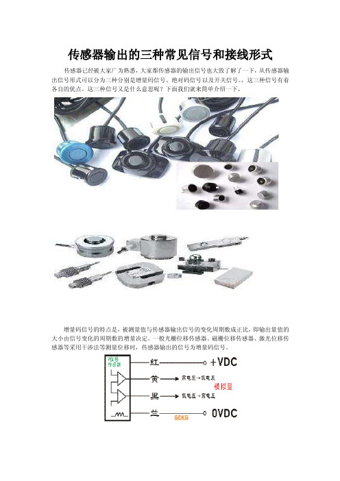
传感器输出的三种常见信号和接线形式传感器已经被大家广为熟悉,大家都传感器的输出信号也大致了解了一下,从传感器输出信号形式可以分为三种分别是增量码信号、绝对码信号以及开关信号。
,这三种信号有着各自的优点。
这三种信号又是什么意思呢?下面我们就来简单介绍一下。
MOD300-150kg称重传感器:h ttp://china.coove/busine ss1/detail/17574417.htmlMOD340-75kg称重传感器:http://china.coove/busine ss1/detail/17574532.htmlMOD460-20t称重传感器:http://china.coove/busine ss1/detail/17574713.htmlMOD460-100t称重传感器:http://china.coove/busine ss1/detail/17574807.htmlMOD540-10t称重传感器:http://china.coove/busine ss1/detail/17575015.htmlMOD700-60t称重传感器:http://china.coove/busine ss1/detail/17575117.htmlMOD740-20t称重传感器:http://china.coove/busine ss1/detail/17575238.htmlMOD740-40t称重传感器:http://china.coove/busine ss1/detail/17575321.htmlMOD740-200t称重传感器:http://china.coove/busine ss1/detail/17575392.htmlMOD740-400t称重传感器:http://china.coove/busine ss1/detail/17575501.htmlMOD750-10t称重传感器:http://china.coove/busine ss1/detail/17575599.htmlBCH-5t称重传感器:http://china.coove/busine ss1/detail/17575783.htmlCBES-500kg称重传感器:h ttp://china.coove/busine ss1/detail/17576070.htmlCBES-1t称重传感器:http://china.coove/busine ss1/detail/17576211.htmlCBES-2t称重传感器:http://china.coove/busine ss1/detail/17576303.htmlCBES-5t称重传感器:http://china.coove/busine ss1/detail/17576342.htmlCBES-10t称重传感器:http://china.coove/busine ss1/detail/17576392.htmlCBFS-100kg称重传感器:h ttp://china.coove/busine ss1/detail/17576471.htmlCSCK-30T称重传感器:http://china.coove/busine ss1/detail/17576686.htmlCSCK-100T称重传感器:http://china.coove/busine ss1/detail/17576751.htmlCDFS-50KG称重传感器:http://china.coove/busine ss1/detail/17576961.htmlCDFS-200kg称重传感器:h ttp://china.coove/busine ss1/detail/17576991.html增量码信号的特点是,被测量值与传感器输出信号的变化周期数成正比,即输出量值的大小由信号变化的周期数的增量决定。
广测YZC称重传感器参考资料

广测YZC称重传感器参考资料广测传感器参照图YZC-522系列拉式S型称重传感器产品型号产品描述YZC-522-50kg 钢制拉式S型称重传感器,容量50KGYZC-522-100kg 钢制拉式S型称重传感器,容量100KGYZC-522-150kg 钢制拉式S型称重传感器,容量150KGYZC-522-200kg 钢制拉式S型称重传感器,容量250KGYZC-522-500kg 钢制拉式S型称重传感器,容量500KGYZC-522-1.5t 钢制拉式S型称重传感器,容量1500KGS型应用于拉伸/拉力测量,试验机,吊钩秤,搅拌站等。
YZC-522TS系列拉式S型称重传感器产品型号产品描述YZC-522TS-50kg 钢制拉式S型称重传感器,容量50KGYZC-522TS-100kg 钢制拉式S型称重传感器,容量100KGYZC-522TS-150kg 钢制拉式S型称重传感器,容量150KGYZC-522TS-200kg 钢制拉式S型称重传感器,容量250KGYZC-522TS-500kg 钢制拉式S型称重传感器,容量500KGYZC-522TS-1.5t 钢制拉式S型称重传感器,容量1500KGS型应用于拉伸/拉力测量,试验机,吊钩秤,搅拌站等YZC-5B(516)系列拉式S型称重传感器产品型号产品描述YZC-5B(516)-20kg 钢制拉式S型称重传感器,容量20KG YZC-5B(516)-30kg 钢制拉式S型称重传感器,容量30KG YZC-5B(516)-50kg 钢制拉式S型称重传感器,容量50KG YZC-5B(516)-100kg 钢制拉式S型称重传感器,容量100KG YZC-5B(516)-150kg 钢制拉式S型称重传感器,容量150KG YZC-5B(516)-200kg 钢制拉式S型称重传感器,容量250KG YZC-5B(516)-500kg 钢制拉式S型称重传感器,容量500KG YZC-5B(516)-750kg 钢制拉式S型称重传感器,容量500KG YZC-5B(516)-1.0t 钢制拉式S型称重传感器,容量1000KG YZC-5B(516)-1.5t 钢制拉式S型称重传感器,容量1500KG YZC-5B(516)-2.0t 钢制拉式S型称重传感器,容量2000KG YZC-5B(516)-3.0t 钢制拉式S型称重传感器,容量3000KGYZC-5B(516)-5.0t 钢制拉式S型称重传感器,容量5000KG YZC-5B(516)-7.5t 钢制拉式S型称重传感器,容量7500KG YZC-5B(516)-10t 钢制拉式S型称重传感器,容量10000KG YZC-5B(516)-20t 钢制拉式S型称重传感器,容量20000KG YZC-5B(516)-30t 钢制拉式S型称重传感器,容量30000KG S型应用于拉伸/拉力测量,试验机,吊钩秤,搅拌站等YZC-328系列压式波纹管称重传感器产品型号产品描述YZC-328-5kg 钢质压式波纹管称重传感器,容量5KGYZC-328-10kg 钢质压式波纹管称重传感器,容量10KGYZC-328-20kg 钢质压式波纹管称重传感器,容量20KGYZC-328-30kg 钢质压式波纹管称重传感器,容量30KGYZC-328-50kg 钢质压式波纹管称重传感器,容量50KGYZC-328-100kg 钢质压式波纹管称重传感器,容量100KG YZC-328-200kg 钢质压式波纹管称重传感器,容量200KG YZC-328-300kg 钢质压式波纹管称重传感器,容量300KG YZC-328-500kg 钢质压式波纹管称重传感器,容量500KG波纹管式应用于平台秤,料斗秤,皮带秤,包装称等。
梅特勒托利多称重传感器

梅特勒托利多称重传感器简介梅特勒托利多(Mettler Toledo)是一家专门从事测量和分析仪器的瑞士公司,是全球称量技术的领导者之一。
梅特勒托利多生产的称重传感器,以其精确、可靠的性能而被全球各行各业广泛应用。
原理梅特勒托利多的称重传感器可分为两类:电子称重传感器和机械式称重传感器。
电子称重传感器电子称重传感器采用应变片或压电陶瓷作为传感元件,通过电子电路转化为输出信号。
这种传感器通常具有较高的灵敏度和可靠性,能够在工业生产过程中实现高精度的重量测量。
机械式称重传感器机械式称重传感器采用弹性体或权重坠子作为传感元件,通过机械结构转化为输出信号。
这种传感器通常具有较高的机械稳定性和耐用性,但精度较低,只适合进行粗略的重量测量。
应用领域梅特勒托利多的称重传感器广泛应用于工业生产、实验室、医疗和交通等领域。
工业生产梅特勒托利多的称重传感器可以用于各种重量测量场合,如压力容器、货车秤等。
实验室梅特勒托利多的称重传感器被广泛应用于实验室中,如天平、分析仪器等。
医疗梅特勒托利多的称重传感器可以用于医疗设备中,如体重秤、血槽秤等。
交通梅特勒托利多的称重传感器可以用于交通设备中,如大型卡车称重、电子收费等。
特点梅特勒托利多的称重传感器具有以下几个特点:精度高梅特勒托利多的称重传感器精度高,可以实现高精度的重量测量。
可靠性强梅特勒托利多的称重传感器可以长期稳定工作,具有较高的可靠性。
维护方便梅特勒托利多的称重传感器结构简单,维护方便,使用寿命长。
结论梅特勒托利多的称重传感器是一种精密、可靠的测量设备,在各个领域都有广泛的应用。
随着科技的发展,梅特勒托利多将会进一步提高称重传感器的性能和可靠性,为全球的称量技术发展做出更大的贡献。
55-30称重模块安装指导书
55-30称重模块安装指导书概述本指南着重于应用方面向用户介绍富林泰克(江苏)测控系统有限公司(以下简称FLINTEC)的称重模块产品。
1.1 称重模块的定义55-30通用性静(动)载称重模块,自复位传力方式,带防扭转拉杆,配置运输和检修维护防过载螺母,整体性好。
它将高精度柱式传感器、载荷传递装置与安装连接板等部件合为一体,既保证了柱式传感器精度高、长期稳定性好的特点,又解决了因安装不当造成的称量误差问题。
55-30静载称重模块主要适用于侧向力较小的静态载荷称重场合。
称重模块可以非常方便地安装在各种形状的容器上。
55-30动载模块主要适用于有水平作用力的称重场合,如流水线、传送带、过程控制系统等,另外动载称重模块还可以方便地将机械衡器改造成全电子衡器。
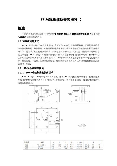
1.2 55-30动载称重模块1.2.1 55-30动载称重模块的组成FLINTEC的55-30动载称重模块由顶板、底板、RC3系列柱式称重传感器、传感器连接件及限位拉杆等部件构成(如下图所示)。
在称量时,载荷作用于顶板,通过传感器连接件施加到传感器上。
1.2.2 FW静载称重模块的容量模块的容量依据其所用的传感器而定,55-30称重模块的容量有7.5t-300t。
1.2.4 侧方定位板与限位拉杆的作用55-30动载称重模块中的侧方限位板,防止传感器在运输和安装过程中受力。
同时在模块需要焊接时,可取出传感器,仅靠侧板支撑,以避免传感器过电流。
限位拉杆具有抵御上抬力和倾覆力的作用,可以避免罐体因晃动过大而造成的计量误差。
2. 模块安装基础的要求模块安装基础应符合以下要求:⚫模块底板撑脚应水平。
⚫与模块顶板和底板相连的撑脚的偏斜引起的与水平线的夹角不能大于0.5°。
⚫每只容器的基础是否与其他容器共享,如果共享将对容器的称量有影响,建议每只容器采用独立的基础。
⚫容器的附近是否有震动或气流,较大的震动或气流将对容器的称量有影响。
⚫每个模块应便于安装和维护。
- 1、下载文档前请自行甄别文档内容的完整性,平台不提供额外的编辑、内容补充、找答案等附加服务。
- 2、"仅部分预览"的文档,不可在线预览部分如存在完整性等问题,可反馈申请退款(可完整预览的文档不适用该条件!)。
- 3、如文档侵犯您的权益,请联系客服反馈,我们会尽快为您处理(人工客服工作时间:9:00-18:30)。
代理【深圳市东本工业自动化设备有限公司】
【应用领域】汽车、冶金、注塑、造纸、电子、半导体、水处理、环保、轮胎、食品、医疗、土木工程等领域的油压机、注塑成型机、轧辊、粉末压制成型机、轮胎及橡胶硫化压榨机、造纸滚筒张力设备、涂装机、PC板和胶合板压制机、热处理真空炉、刹车油的真空填充装置、半导体液晶的真空装置、压缩机、空压机、过滤机、油罐、烧结冲压机等。
称重传感器型号:
VLC-()E344、VLC-()H229、VLC-()J544、VLC-()087、VLS、VLC-()-003/004、VLSS、VLC-()H333M1H、VC2AC3、VC9B、VLC-()G471M2、VLC-()G811、VLC-()G510A、VU93、VKMR、VLC-()020/021、VLC-15KNG787、VLC-023、VU9B、VS2、VC6A、VC6A-5MN、VRTNC3、VRTN/M2LB、VHLC3、VHLC3/MLBR、VZ6FC3、VZ6FC3/MLR、VPW22C3、VPW18C3、VPW15AHC3、VPW4MC3、VSP4C3、VPW6DC3、VPW10AC3、VPW12CC3、FIT5、VLTT、VJBX-4、VKK1-4
型号举例:
1.VLS-0.5K
2.VLS-1K
3.VLS-2K
4.VLS-5K
5.VLS-10K
6.VLS-20K
7.VLS-50K
8.VLS-100K
9.VLC-20N-004
10.VLC-50N-004
11.VLC-100N-003
12.VLC-200N-003
13.VLC-500N-003
14.VLC-1KN-003。