2009年我国卫生事业发展情况公布乡镇卫生院病床使用率达到59.4%
国家质量监督检验检疫总局公告2009年2号--关于出口美国全地形车(ATV)有关事项的通告
国家质量监督检验检疫总局公告2009年2号--关于出口美国全地形车(ATV)有关事项的通告文章属性•【制定机关】国家质量监督检验检疫总局(已撤销)•【公布日期】2009.04.03•【文号】国家质量监督检验检疫总局公告2009年2号•【施行日期】2009.04.13•【效力等级】部门规范性文件•【时效性】现行有效•【主题分类】质量管理和监督正文国家质量监督检验检疫总局公告(2009年2号)关于出口美国全地形车(ATV)有关事项的通告近期,美国消费品安全委员会(以下简称CPSC)就《消费品安全改进法案》的有关规定做出通报:自2009年4月13日起,除非全地形车的制造商或分销商已向CPSC递交所经营的全地形车产品的安全行动计划并获得批准,且遵守所批准的安全行动计划和美国标准(ANSI/SVIA 1-2007)的要求,否则在美国,该类全地形车产品的进口或销售均属于非法。
2008年8月13日之后提交的安全行动计划必须获得CPSC批准(http:///businfo/intl/section232ch.html)。
同时,大多数青少年用全地形车还必须符合CPSC关于儿童产品的新要求。
另据了解,按照《消费品安全改进法案》的规定,全地形车还需具有相应标签(证明符合标准、标明制造商或进口商或私人标签者、所遵守的安全行动计划等)。
为减小美国《消费品安全改进法案》对我国相关产品出口的影响,避免2009年4月13日后,我国出口的全地形车因不符合美国CPSC的要求而被美国口岸部门退运或销毁,现将全地形车(HS编码:8703101100)出口美国有关事项通告如下:一、各出口企业须高度重视美国有关法律法规的要求,在前期准备的基础上,继续跟踪美国官方要求,在产品出口前做好自我检查,避免不必要的贸易损失。
有关详细内容,可在美国CPSC的官方网站上查询。
浙江金华出入境检验检疫局对美国标准ANSI/SVIA 1-2007进行了研究,并在其网站()提供了中文参考译文,可供各企业参考。
2009年度第三批达国Ⅳ排放标准的轻型汽车(带OBD)

附件1:2009年度第三批达国Ⅳ排放标准的轻型汽车(带OBD)(下文出现的“*”代表随机变动实号,“(*)”代表随机变动实号或虚号)1、RENAULT s.a.sVYRTY 多用途乘用车VYRTE 运动型多用途乘用车发动机:2TRA703(NISSAN)机外净化器:前:JY0(NISSAN)后:JG8(NISSAN)燃油蒸发控制装置:149506N201(MAHLE TENNEX)氧传感器:前:211200-7040(DENSO)后:OZA603-N9(NTK)2、安徽江淮汽车股份有限公司HFC7200ETF 轿车发动机:HFC4GA3.1C(安徽江淮汽车股份有限公司)机外净化器:WLDQJ4011(无锡威孚力达催化净化器有限责任公司)燃油蒸发控制装置:GL-Ⅱ(天津市格林利福新技术有限公司)氧传感器:前:RE94(北京德尔福万源发动机管理系统有限公司)后:RE94(北京德尔福万源发动机管理系统有限公司)3、北京汽车制造厂有限公司BJ5021TJL13 教练车发动机:4G22D4(沈阳新光华晨汽车发动机有限公司)机外净化器:前:M25(DELPHI)后:M102(DELPHI)燃油蒸发控制装置:YX1104210(廊坊远祥汽车配件有限公司)氧传感器:前:RE94(DELPHI)后:RE94(DELPHI)或机外净化器:前:M25(DELPHI)后:M102(DELPHI)燃油蒸发控制装置:GL-Ⅱ(天津市格林利福新技术有限有限公司)氧传感器:前;RE94(DELPHI)后:RE94(DELPHI)4、北京市清洁机械厂BQJ5021GSS 洒水车发动机:JL466Q4(重庆长安汽车股份有限公司)机外净化器:KD-FⅥ(重庆长安汽车股份有限公司)燃油蒸发控制装置:GL-I(天津格林利福新技术有限公司)氧传感器:前:LSF4(联合汽车电子有限公司)后:LSH25(联合汽车电子有限公司)或机外净化器:KD-FⅥ(重庆长安汽车股份有限公司)燃油蒸发控制装置:FY(重庆方圆工贸有限公司)氧传感器:前:LSF4(联合汽车电子有限公司)后:LSH25(联合汽车电子有限公司)5、北汽福田汽车股份有限公司BJ5020V2DV2-X 厢式运输车BJ5020V2DV2-X1 仓栅式运输车BJ5020V3BV2-X 仓栅式运输车BJ5020V2BV2-X 厢式运输车BJ1020V2AV2-X 载货汽车BJ1020V3JV2-X 载货汽车发动机:LJ465Q-2AE(柳州五菱柳机动力有限公司)机外净化器:1101020000036(杭州德力西三元催化器有限公司)燃油蒸发控制装置:GL-Ⅰ(天津市格林利福新技术有限公司)氧传感器:前:SE4-276(SNG)后:SG4-31(SNG)6、德国宝马汽车公司BMW Z4 sDrive23i LM31 敞篷轿车发动机:N52B25BF(BMW)机外净化器:左:7 591 447(BMW)右:7 591 447(BMW)燃油蒸发控制装置:6 764 044(Delphi)氧传感器:左前:LSU 4.9(Bosch)右前:LSU 4.9(Bosch)左后:LSF 4.2(Bosch)右后:LSF 4.2(Bosch)BMW Z4 sDrive30i LM51 敞篷轿车发动机:N52B30BF(BMW)机外净化器:左:7 591 446(BMW)右:7 591 446(BMW)燃油蒸发控制装置:6 764 044(Delphi)氧传感器:左前:LSU 4.9(Bosch)右前:LSU 4.9(Bosch)左后:LSF 4.2(Bosch)右后:LSF 4.2(Bosch)BMW Z4 sDrive35i LM71 敞篷轿车发动机:N54B30A(BMW)机外净化器:左前/右前:7 591 480(BMW)左后/右后:7 589 585(BMW)燃油蒸发控制装置:6 764 044(Delphi)氧传感器:左前:LSU 4.9(Bosch)右前:LSU 4.9(Bosch)左后:LSF 4.2(Bosch)右后:LSF 4.2(Bosch)7、东风柳州汽车有限公司LZ6512AQ7S 多用途乘用车LZ6512AQ7SQ 多用途乘用车发动机:4G63S4M(沈阳航天三菱汽车发动机制造有限公司)机外净化器:前:A-1205030(上海德尔福排气控制系统有限公司)后:A-1205040(上海德尔福排气控制系统有限公司)燃油蒸发控制装置:1104MT-010(厦门信源环保科技有限公司)氧传感器:前:RE94(DELPHI)后:RE94(DELPHI)LZ6470AQAS 多用途乘用车LZ6510AQAS 多用途乘用车LZ6510AQASN 多用途乘用车LZ6510AQASQ 多用途乘用车发动机:4G69S4N(沈阳航天三菱汽车发动机制造有限公司)机外净化器:前:A-1205030(上海德尔福排气控制系统有限公司)后:A-1205040(上海德尔福排气控制系统有限公司)燃油蒸发控制装置:1104MT-010(厦门信源环保科技有限公司)氧传感器:前:RE94(北京德尔福技术开发有限公司)后:RE94(北京德尔福技术开发有限公司)8、东风汽车有限公司DFL7162ACC 轿车发动机:HR16(东风汽车有限公司)机外净化器:前:EW5***(广州三五汽车部件有限公司)后:CJ0***(广州三五汽车部件有限公司)燃油蒸发控制装置:14950 EN200(飞得滤机(苏州)有限公司)氧传感器:前:OZA603-**(*)(上海特殊陶业有限公司(NTK))后:OZA603-**(*)(上海特殊陶业有限公司(NTK))DFL7162MCC 轿车发动机:HR16(东风汽车有限公司)机外净化器:前:EW5***(广州三五汽车部件有限公司)后:CJ0***(广州三五汽车部件有限公司)燃油蒸发控制装置:14950 EN200(飞得滤机(苏州)有限公司)氧传感器:前:OZA603-**(*)(上海特殊陶业有限公司(NTK))后:OZA603-**(*)(上海特殊陶业有限公司(NTK))DFL7200VCC 轿车发动机:MR20(东风汽车有限公司)机外净化器:前:EW6***(广州三五汽车部件有限公司)后:EW8***(广州三五汽车部件有限公司)燃油蒸发控制装置:14950 EN200(飞得滤机(苏州)有限公司)氧传感器:前:OZA603-**(*)(上海特殊陶业有限公司(NTK))后:OZA603-**(*)(上海特殊陶业有限公司(NTK))9、合肥昌河汽车有限责任公司CH7101CE4 轿车发动机:DA465Q-2(哈尔滨东安汽车动力股份有限公司)机外净化器:前:7101E4-1205100(安格环保技术(上海)有限公司)后:7101E4-1205200(安格环保技术(上海)有限公司)燃油蒸发控制装置:18560-83F00(83F0)(北京德尔福万源发动机管理系统有限公司)氧传感器:前:LSF 4.2(联合汽车电子有限公司)后:LSF 4(联合汽车电子有限公司)CH6390FE4 客车发动机:DA465QE-1A(哈尔滨东安汽车动力股份有限公司)机外净化器:6390E4-1201200(庄信万丰化工有限公司)燃油蒸发控制装置:QYK1129C(18560-C30E0)(固安远祥汽车配件厂)氧传感器:前:LSF 4.2(联合汽车电子有限公司)后:LSF 4(联合汽车电子有限公司)CH6390FHE4 客车发动机:DA465QE-1A(哈尔滨东安汽车动力股份有限公司)机外净化器:6390E4-1201200(庄信万丰化工有限公司)燃油蒸发控制装置:QYK1129C(18560-C30E0)(固安远祥汽车配件厂)氧传感器:前:LSF 4.2(联合汽车电子有限公司)后:LSF 4(联合汽车电子有限公司)10、湖南江南汽车制造有限公司JNJ6406A1 轻型客车发动机:4G13S1(哈尔滨东安汽车发动机制造有限公司)机外净化器:前:HVC-ZTAQ4-01(湖南威斯特汽车零配件有限公司)后:HVC-ZTAQ4-02(湖南威斯特汽车零配件有限公司)燃油蒸发控制装置:GL型(天津格林利福新技术有限公司)氧传感器:前:LSF 4(联合汽车电子有限公司)后:LSF 4(联合汽车电子有限公司)JNJ6406B1 轻型客车发动机:4G15S(哈尔滨东安汽车发动机制造有限公司)机外净化器:前:HVC-ZTAQ4-01(湖南威斯特汽车零配件有限公司)后:HVC-ZTAQ4-02(湖南威斯特汽车零配件有限公司)燃油蒸发控制装置:GL型(天津格林利福新技术有限公司)氧传感器:前:LSF 4 (联合汽车电子有限公司)后:LSF 4 (联合汽车电子有限公司)11、奇瑞汽车股份有限公司SQR7151A217 轿车发动机:SQR477F(奇瑞汽车股份有限公司)机外净化器:预催:WLDJ149C(无锡威孚力达催化净化器有限责任公司)主催:WLDJ149C(无锡威孚力达催化净化器有限责任公司)燃油蒸发控制装置:MWV A1X00CC(武汉神龙汽车塑胶件制造有限公司)氧传感器:前:LSF4(联合汽车电子有限公司)后:LSF4(联合汽车电子有限公司)或机外净化器:预催:WLDJ149C(无锡威孚力达催化净化器有限责任公司)主催:WLDJ149C(无锡威孚力达催化净化器有限责任公司)燃油蒸发控制装置:MWV A1X00CC(上海马勒滤清系统有限责任公司)氧传感器:前:LSF4(联合汽车电子有限公司)后:LSF4(联合汽车电子有限公司)SQR7130S21T7 轿车发动机:SQR473F(奇瑞汽车股份有限公司)机外净化器:WLDJ149C(无锡威孚力达催化净化器有限责任公司)燃油蒸发控制装置:MWV A1X00CC(武汉神龙汽车塑胶件制造有限公司)氧传感器:前:OZA522-BB1(NTK)后:OZA522-BB1(NTK)或机外净化器:WLDJ149C(无锡威孚力达催化净化器有限责任公司)燃油蒸发控制装置:MWV A1X00CC(廊坊华安汽车装备有限公司)氧传感器:前:OZA522-BB1(NTK)后:OZA522-BB1(NTK)SQR7130S12T7 轿车发动机:SQR473F(奇瑞汽车股份有限公司)机外净化器:WLDJ149C(无锡威孚力达催化净化器有限责任公司)燃油蒸发控制装置:MWV A1X00CC(武汉神龙汽车塑胶件制造有限公司)氧传感器:前:OZA522-BB1(NTK)后:OZA522-BB1(NTK)或机外净化器:WLDJ149C(无锡威孚力达催化净化器有限责任公司)燃油蒸发控制装置:MWV A1X00CC(廊坊华安汽车装备有限公司)氧传感器:前:OZA522-BB1(NTK)后:OZA522-BB1(NTK)12、日本丰田汽车公司TRH223L-LEPNK4 商用车发动机:2TR(TOYOTA)机外净化器:前:T75(TOYOTA)后:U75(TOYOTA)燃油蒸发控制装置:77704-*****(AISAN)氧传感器:前:89467-*****(DENSO)后:89465-*****(DENSO)TRH213L-JDMNK4 商用车TRH223L-LEMNK4 商用车发动机:2TR(TOYOTA)机外净化器:前:T75(TOYOTA)后:U75(TOYOTA)燃油蒸发控制装置:77704-*****(AISAN)氧传感器:前:89467-*****(DENSO)后:89465-*****(DENSO)ACR50L-GFPGK4 乘用车发动机:2AZ(TOYOTA)机外净化器:前:28***(TOYOTA)后:GB3(TOYOTA)燃油蒸发控制装置:77704-*****(AISAN)氧传感器:前:89467-*****(NTK或DENSO)后:89465-*****(NTK或DENSO)13、上海大众汽车有限公司SVW7183SJD 轿车发动机:CED(上海大众汽车有限公司)机外净化器:8D0 178 BE(EBERSPAECHER)燃油蒸发控制装置:3BD 201 803*(河北华安汽车装饰装置公司)氧传感器:前:LU10(BOSCH(联合汽车电子有限公司转口贸易))后:LF07(BOSCH(联合汽车电子有限公司转口贸易))或机外净化器:3BD 178 CN(大连华克-埃贝斯佩歇汽车排气系统有限公司)燃油蒸发控制装置:3BD 201 803*(河北华安汽车装饰装置公司)氧传感器:前:LU10(BOSCH(联合汽车电子有限公司转口贸易))后:LF07(BOSCH(联合汽车电子有限公司转口贸易))SVW7183TJD 轿车发动机:CED(上海大众汽车有限公司)机外净化器:3BD 178 CN(大连华克-埃贝斯佩歇汽车排气系统有限公司)燃油蒸发控制装置:3BD 201 803*(河北华安汽车装饰装置公司)氧传感器:前:LU10(BOSCH(联合汽车电子有限公司转口贸易))后:LF07(BOSCH(联合汽车电子有限公司转口贸易))或机外净化器:8D0 178 BE(EBERSPAECHER)燃油蒸发控制装置:3BD 201 803*(河北华安汽车装饰装置公司)氧传感器:前:LU10(BOSCH(联合汽车电子有限公司转口贸易))后:LF07(BOSCH(联合汽车电子有限公司转口贸易))SVW7203UPD 轿车发动机:BNL(上海大众汽车有限公司)机外净化器:3BD 131 701(大连华克-埃贝斯佩歇汽车排气系统有限公司)燃油蒸发控制装置:3BD 201 803*(河北华安汽车装饰装置公司)氧传感器:前:LU10(BOSCH(联合汽车电子有限公司转口贸易))后:LF07(BOSCH(联合汽车电子有限公司转口贸易))或机外净化器:3B0 131 701**(EBERSPAECHER)燃油蒸发控制装置:3BD 201 803*(河北华安汽车装饰装置公司)氧传感器:前:LU10(BOSCH(联合汽车电子有限公司转口贸易))后:LF07(BOSCH(联合汽车电子有限公司转口贸易))SVW7203VPD 轿车发动机:BNL(上海大众汽车有限公司)机外净化器:3BD 131 701(大连华克-埃贝斯佩歇汽车排气系统有限公司)燃油蒸发控制装置:3BD 201 803*(河北华安汽车装饰装置公司)氧传感器:前:LU10(BOSCH(联合汽车电子有限公司转口贸易))后:LF07(BOSCH(联合汽车电子有限公司转口贸易))或机外净化器:3B0 131 701**(EBERSPAECHER)燃油蒸发控制装置:3BD 201 803*(河北华安汽车装饰装置公司)氧传感器:前:LU10(BOSCH(联合汽车电子有限公司转口贸易))后:LF07(BOSCH(联合汽车电子有限公司转口贸易))SVW7283WKD 轿车发动机:BBG(德国大众)机外净化器:前:8D0 178 BF/8D0 178 BG(Leistritz)后:8D0 178 AM/8D0 178AS(Faurecia)燃油蒸发控制装置:3BD 201 803*(河北华安汽车装饰装置公司)氧传感器:前:LF07(BOSCH(联合汽车电子有限公司转口贸易))后:LF07(BOSCH(联合汽车电子有限公司转口贸易))14、上海通用(沈阳)北盛汽车有限公司SGM7169MTA 轿车发动机:LDE(通用汽车匈牙利动力总成有限公司)机外净化器:GM 185(Benteler Automobiltechnik GmbH)燃油蒸发控制装置:CC 185(MAHLE)氧传感器:前: OZA 619(Continental/大陆汽车电子(长春)有限公司)后: OZA 619(Continental/大陆汽车电子(长春)有限公司)SGM7169ATA 轿车发动机:LDE(通用汽车匈牙利动力总成有限公司)机外净化器:GM 185(Benteler Automobiltechnik GmbH)燃油蒸发控制装置:CC 185(MAHLE)氧传感器:前: OZA 619(Continental/大陆汽车电子(长春)有限公司)后: OZA 619(Continental/大陆汽车电子(长春)有限公司)SGM7184ATA 轿车发动机:2HO(通用汽车匈牙利动力总成有限公司)机外净化器:GM 185(Benteler Automobiltechnik GmbH)燃油蒸发控制装置:CC 185(MAHLE)氧传感器:前: OZA 619(Continental/大陆汽车电子(长春)有限公司)后: OZA 619(Continental/大陆汽车电子(长春)有限公司)15、沈阳华晨金杯汽车有限公司SY7150WSBAA 轿车发动机:4A15(绵阳新晨动力机械有限公司)机外净化器:WLDQJ4007(无锡威孚力达催化净化器有限责任公司)燃油蒸发控制装置:QXTZ80(南京宏光空降装备厂)氧传感器:前:RE94(北京德尔福万源发动机管理系统有限公司)后:RE94(北京德尔福万源发动机管理系统有限公司)16、天津一汽丰田汽车有限公司TV6460GLM 多用途乘用车TV6460GLMNAVi 多用途乘用车TV6460DLXM 多用途乘用车发动机:1AZ(广汽丰田发动机有限公司)机外净化器:前:28340(前:TOYOTA MOTOR CORPORA TION)后:GJ9(后:天津三五汽车部件有限公司)燃油蒸发控制装置:77704-0R010(爱三(天津)汽车部件有限公司)氧传感器:前:89467-58030(前:DENSO CORPORA TION)后:89465-42170(后:NGK SPARK PLUG CO.,LTD)或机外净化器:前:28340 (前:TOYOTA MOTOR CORPORA TION)后:GJ9(后:天津三五汽车部件有限公司)燃油蒸发控制装置:77704-0R010(爱三(天津)汽车部件有限公司)氧传感器:前:89467-58030(前:DENSO CORPORA TION)后:89465-42170(后:NGK SPARK PLUG CO.,LTD)TV6460GL 多用途乘用车TV6460GLNAVi 多用途乘用车TV6460DLX 多用途乘用车发动机:1AZ(广汽丰田发动机有限公司)机外净化器:前:28340(前:TOYOTA MOTOR CORPORA TION)后:GJ9(后:天津三五汽车部件有限公司)燃油蒸发控制装置:77704-0R010(爱三(天津)汽车部件有限公司)氧传感器:前:89467-58030(前:DENSO CORPORA TION)后:89465-42170(后:NGK SPARK PLUG CO.,LTD)TV6460GLX-iM 多用途乘用车TV6460GLX-iMNA Vi 多用途乘用车发动机:2AZ(广汽丰田发动机有限公司)机外净化器:前:28340(前:TOYOTA MOTOR CORPORA TION)后:GJ9(后:天津三五汽车部件有限公司)燃油蒸发控制装置:77704-0R010(爱三(天津)汽车部件有限公司)氧传感器:前:89467-58030 (前:DENSO CORPORA TION)后:89465-42170(后:NGK SPARK PLUG CO.,LTD)或机外净化器:前:28340(前:TOYOTA MOTOR CORPORA TION)后:GJ9(后:天津三五汽车部件有限公司)燃油蒸发控制装置:77704-0R010(爱三(天津)汽车部件有限公司)氧传感器:前:89467-58030(前:DENSO CORPORA TION)后:89465-42170(后:NGK SPARK PLUG CO.,LTD)TV6460GLX-i 多用途乘用车TV6460GLX-iNAVi 多用途乘用车发动机:2AZ(广汽丰田发动机有限公司)机外净化器:前:28340(前:TOYOTA MOTOR CORPORA TION)后:GJ9(后:天津三五汽车部件有限公司)燃油蒸发控制装置:77704-0R010(爱三(天津)汽车部件有限公司)氧传感器:前:89467-58030(前:DENSO CORPORA TION)后:89465-42170(后:NGK SPARK PLUG CO.,LTD)17、天津一汽夏利汽车股份有限公司CA7150E4 轿车CA7150E4Z1 轿车发动机:5A+(天津一汽丰田发动机有限公司)机外净化器:T1A20(大连华克吉来特汽车消声器有限公司)燃油蒸发控制装置:77740-0DA30(天津市格林利福新技术有限公司)氧传感器:前级:RE94(DELPHI)后级:RE94(DELPHI)18、通用汽车公司Escalade Hybrid 越野车发动机:LFA(通用汽车公司)机外净化器:左: 12585307 (Katcon)右:12585308(Katcon)燃油蒸发控制装置:15113366(Expert)氧传感器:前左:12583804(Denso)前右:12583804(Denso)后左: 12609457(NTK)后右: 12609457(NTK)19、浙江中誉汽车有限公司ZZY6540 商务车发动机:112(戴姆勒股份公司)机外净化器:前:KT6032(戴姆勒股份公司)后:KT6027(戴姆勒股份公司)燃油蒸发控制装置:AF0011(戴姆勒股份公司)氧传感器:前:OS 0005(戴姆勒股份公司)后:OS 0005(戴姆勒股份公司)20、郑州日产汽车有限公司ZN5021XJHV1J4 救护车发动机:PSA RFN 10LH3X(神龙汽车有限公司)机外净化器:前:TR PSA K396(武汉佛吉亚通达排气系统有限公司)后:20010 V0100(德尔福汽车系统(中国)投资有限公司)燃油蒸发控制装置:14950 6N208(厦门信源环保科技有限公司)氧传感器:前:OSP+(DELPHI)后:OSP+(DELPHI)ZN1033F2G4 多用途货车ZN5033XLCF2G4 冷藏车发动机:KA24(日本日产公司)机外净化器:前:V****(日本日产公司)后:VD9**(日本日产公司)燃油蒸发控制装置:14950 *****(日本TENNEX)氧传感器:前:OZA***-**(日本NTK)后:OZA***-**(日本NTK )21、中国第一汽车集团公司CA7206AT 轿车CA7207A T 轿车发动机:LF(中国第一汽车集团公司)机外净化器:LFN3(TOKYO ROKI)燃油蒸发控制装置:FS5R(AISAN)氧传感器:前:A5(*)(*)(*)(*)(*)(NTK)后:S84(*)(*)(*)(*)(*)(NTK)CA7206MT 轿车发动机:LF(中国第一汽车集团公司)机外净化器:LFN2(TOKYO ROKI)燃油蒸发控制装置:FS5R(AISAN)氧传感器:前:A5(*)(*)(*)(*)(*)(NTK)后:S84(*)(*)(*)(*)(*)(NTK)CA7256AT 轿车CA7257A T 轿车发动机:L5(中国第一汽车集团公司)机外净化器:L503(YUMEX)燃油蒸发控制装置:FS5R(AISAN)氧传感器:前:A5(*)(*)(*)(*)(*)(NTK)后:S84(*)(*)(*)(*)(*)(NTK)。
hs编码2009 61号(1)
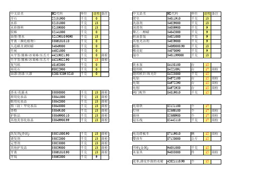
复写纸
48162000
雨花石
68022900
油漆/清漆/大漆
3208/3209/3210
单位 千克 千克 千克 千克 千克 千克 千克 千克 千克 千克 千克 千克 千克
退税 备注 0 13 13 0 13 0 0 0 0 商检 13 商检 0 0 0
香水/花露水 唇用化妆品 眼用化妆品 指(趾)甲化妆品 香粉 护肤品 其他美容化妆品
HS代码 34011910 34029000 34039900 34042000 34051000 34059000 34060000.90 34070090 3401199000
单位 千克 千克 千克 千克 千克 千克 千克 千克 千克
退税 备注 13 13 9 9 9 9 13 9 13
84138100 84521091 84523000 84672100 84672290 84672920 84819010
千克 千克 千克 千克 千克 千克 千克 千克 千克 千克
13 商检 13 商检 13 商检 13 商检 13 商检 13 商检 13 商检 13 商检 13 商检 13 商检
皮革,漆皮作面的箱包 塑料,纺织作面的箱包 皮革手提包 手提包 手提袋 化妆盒 钱包 票夹 眼镜盒 CD包 塑料首饰盒/化妆盒 笔袋 文具盒
千克 13 千克 13 千克 13 千克 13 千克 13 千克 13 千克 13
塑料杯垫 西服套 塑料杯架 塑料冰杯 塑料冰格 塑料餐垫 塑料茶垫 蛋糕器 调酒棒 调味盒
39241000 39241000 39241000 39241000 39241000 39241000 39241000 39241000 39241000 39241000
IWA2009展会新品收视(Ⅲ)

IWA2009展会新品收视(Ⅲ)
余宏建;王英松
【期刊名称】《轻兵器》
【年(卷),期】2009(000)016
【摘要】巴基斯坦政府狩猎运动武器公司的两款手枪从外形上一看就知道,这两款手枪是以前苏联TT-33手枪为基础设计的。
但其并不是完全仿制原型手枪,还有很浓郁的中国风格,如枪上铭文格式就与我国54式手枪很相似。
图中这两款手枪采用大型握把,这一特点与中国北方公司生产的201C手枪极为相似。
【总页数】4页(P6-9)
【作者】余宏建;王英松
【作者单位】(Missing);(Missing)
【正文语种】中文
【相关文献】
1.一场展会和它倡导的生活:CeBIT酷世代新品秀——酷世代的新品秀
2.新春新品新亮点——第九届AAITF展会新品总揽
3.6.30"纸""卫"新品订货节暨CLOUD EXPO of Tissue,AHPs,Wipes and Nonwovens全球云展会成功举办
4.从CPCA 上海展会看覆铜板新品的发展热点
5.海外展会新品童车精选
因版权原因,仅展示原文概要,查看原文内容请购买。
ProMinent gamma L 电动隔膜计量泵说明书
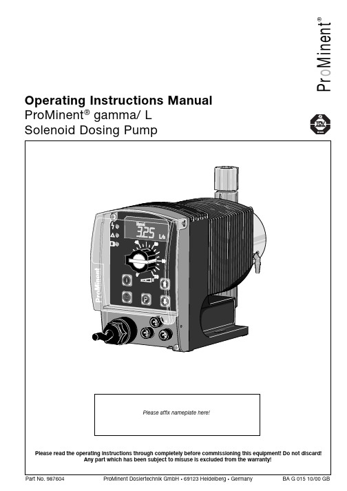
P r o M i n e n t®Operating Instructions Manual ProMinent ® gamma/ L Solenoid Dosing PumpPrintingPrinting:Operating Instructions ProMinent® gamma/ L© ProMinent Dosiertechnik GmbH, 1999Address:ProMinent Dosiertechnik GmbHIm Schuhmachergewann 5-11D-69123 HeidelbergPostfach 101760D-69007 Heidelberg*****************www.prominent.deSubject to technical alteration.Please fold out this page! ÈOperating-/Settings DiagramContinuous displayFunction DescriptionOperating modes Operating modes are selected using the MODE menu (depending upon identity code, someoperating modes may be absent)..“Analogue” operating mode: (Identity code, control variant: analogue current)The stroke rate is controlled via an analogue electrical signal via the “external control” terminal.Signal processing is pre-selected at the controller.“Manual” operating mode: (Identity code, control variant: manual, standard function)The stroke rate is controlled manually via the controller.“Contact” operating mode: (Identity code, control variant: external 1:1 / external with pulsecontrol)This operating mode offers the opportunity to make fine adjustments with small increase/decrease factors. Dosing can be activated by a pulse via the “external control” terminal or by asemiconductor element. With the “pulse control” option it is possible to pre-set a feed quantity(batch) or number of strokes (factor 0.01 to 99.99) via the control unit.“Batch” operating function: (identity code, control variant, external 1:1 / external with pulsecontrol)This operating mode offers the option of working with larger transfer factors (up to 65535).Metering can be triggered by pressing the P key or a pulse from the “external control” terminalvia a contact or semiconductor element. A batching quantity or number of strokes can be pre-selected via the control unit.Functions The following functions can be selected using the SET menu:“Calibrate” function:The gamma/ L can be operated in all operating modes including in calibrating mode. Thecorresponding continuous displays can show the actual feed quantity or the feed rate.Calibration is maintained within the stroke frequency range 0 - 180 strokes/ min. Calibration isalso maintained when a stroke frequency is altered up to ± 10 %.“Pressure level” function:It is possible to set different pressure levels.“Auxiliary frequency” function:It is possible to set a stroke rate in the SET menu, which may be activated via the “externalcontrol” terminal. This auxiliary frequency overrides all other pre-set stroke rate frequencies.“Flow” function:Stops the gamma/ L when the flow is insufficient. In the SET menu, the number of failed strokesis entered after which the pump will be turned off.The following functions are available as standard:“Float switch” function:Information on the liquid level in the feed chemical container is transmitted to the gamma/ L.This option requires the installation of a 2-stage float switch. This is connected to the “floatswitch” terminal.“Pause” function:The gamma/ L can be stopped by remote control via the “external control” terminal. The “pau-se” function operates only via the “external control” terminal.The following functions are activated by keystrokes:“Stop” function:The gamma/ L can be stopped by pressing the STOP/START key without disconnecting fromthe mains power supply.Function Description“Prime” function:Priming (short term feed at maximum frequency) is activated by pressing both arrow keys at thesame time.Optional relay The gamma/ L has two connection options.“Fault indicating relay” option:In the event of fault signals, warning signals or float switch activation signals, connects anelectrical circuit to trigger alarm sirens etc. The relay is retrofitted via an aperture in the powerend.“Fault indicating and pacing relay” option:Along with the fault indicating relay, the pacing relay produces an electrical impulse for everystroke. The relay is retrofitted via an aperture in the power end.Function and errorindicators The operating and error status is shown via the three LEDs and the “error” indicator on the LCD (see also section 12):LCD indicator If a fault occurs “error” will appear along with an additional fault warning.LED indicator Operating indicator (green)This indicator is lit as long as the gamma/ L is operating correctly.Warning indicator (yellow)This warning light appears if the gamma/ L electronics detect a situation that could lead to afault, e.g. “liquid levels low 1st stage”.Warning indicator (red)This warning light appears if a fault occurs, e.g. “liquid levels low 2nd stage”.Hierarchy of operating modes, functions and fault statusesThe different operating modes, functions and fault statuses each have a differing effect onwhether and how the gamma/ L functions. These effects are given below:1.Prime2.Fault, stop, pause3.Auxiliary frequency4.Manual, analogue, contact, batchto:1.“Prime” can be activated in any pump status (as long as it is operable)2.“Fault”, “stop” and “pause” stop all system parts up to “prime”.3.The stroke rate of the “auxiliary frequency” always overrides the existing operating strokerate.Commissioning / Operating8.2Diagrams for setting feed capacityGeneralS Open out the page showing the diagram of your pump type (see appendix).S Calculate the correction factor. Mark the operating pressure for your application in the dia-gram “correction factor depending upon operating pressure”.S Trace a line from this value vertically up to the curve and then horizontally left. Read off thecorrection factor.S Divide the required feed rate by the correction factor determined as above. Mark this value(l/h) on the “l/h” axis in the diagram “feed rate depending upon stroke length and strokerate”.S Trace a line horizontally from this value to the left. Trace a line from the intersection with thestraight line for the adjustable stroke frequencies vertically downwards to the “strokelength” axis.S Set the gamma/ L to one of the stroke frequencies determined in this way, and thecorresponding stroke length.The measurements for determining the feed rate for the following diagrams were carried outusing water and the correction factor was determined at a 70 % stroke length. Distribution ofthe feed rate across all material versions: -5 to +15 %.9OperatingThis section describes all operating options available to you when the gamma/ L is incontinuous display mode (no P key symbol in the LCD display).GUIDELINE•Open out the fold-out page following the title page fully! There you will find theoverviews “control elements and key functions” and “operating settings dia-gram”.•Look at the overview “continuous displays”. This page shows you which displaysare available in which operating mode, and which values are directly alterable inthe corresponding continuous displays.9.1Manual operationSet stroke length Stroke length is continually adjustable within a range of 0 - 100 %. The recommended strokelength range, which will practically guarantee technical reproducibility, is 30 - 100 % (SEK type:50 - 100 %).The following operating options are available via the different keys (see also figure on the nextpage):Stop/Start gamma/ L To stop gamma/ L: press STOP/START key.To start gamma/ L: press STOP/START key.Start batch Press the P key briefly in “batch” operating mode.Load factory settings Press the P key for 15 s to load factory calibration settings!Current settings will be deleted.Change to settings mode WeIf you press the P key for 2 s in any continuous display the gamma/ L will change to settingsmode (see section 7).If CODE 1 is set, the code must be entered after pressing the P key.Check adjustable values Each time you press the i key you will see a different continuous display. The number ofcontinuous displays depends upon the identity code, the selected operating mode and theconnected accessories.Change directlyalterable values To change a value (see below) directly in the corresponding continuous display, press one of thearrow keys until “set” appears in the LCD display. The delay has been programmed in to preventinadvertent changing of values.If CODE 2 has been set, this code must be entered after pressing the arrow key.Directly alterable values are as follows:。
2009年CLSI更新

新
CLSI的AST标准 2009年1月
M100-S19 表格(2009)* M02-A10 纸片扩散法(2009)** M07-A8 MIC 方法(2009)**
*M100每年更新一次 **M02,M07每3年更新一次
2009年的CLSI AST标准的主要 改变
VISA-以前的假“S”株(CLSIM100- S18)万古霉素纸片扩散法折点
金黄色葡萄球菌
万古霉素的抑菌环直径与MIC比对
以前(2008)折点15mm
抑菌环直径(mm)
汇报葡萄球菌万古霉素试验的策略
选择性的做万古霉素的MIC(如可能会使用万 古霉素的情况) 常规检测万古霉素的MIC 金黄色葡萄球菌 -在所有的DD平皿上贴万古霉素纸片筛选 VRSA -BHI琼脂筛选(注:不能检测MIC=4 μg/ml 的VISA) 金黄色葡萄球菌和CoNS的万古霉素结果对于正 在使用和已经用过万古霉素的患者十分重要。 其他
新的“折点”表格2A-2L (DD和 MIC在一个表格里)
AST实验条件小结(以前没有过)
对表格进行重组导致……
“以前列在表2A-2L中的一些要求或实验 推荐方法现在出现在附录A—G(M100S19)或分出去在M02-A10或M07-A8 ”
很重要!
“非敏感”的解释
对于只有敏感折点的菌株/药物组合,可能是由于 一种新的抗微生物制剂在其刚制定折点时还未遇 到过耐药菌株。如果菌株的 MIC 高于敏感折点则 认为是非敏感,这样的情况不一定意味着该菌株 中存在某种耐药基因。这一非敏感的 MIC 值可能 也是野生型菌株药敏结果中曾出现的,但是对于 这 样 菌 株 的 临 床 治 疗 的 经 验 有 限 。
Design Guide for Two DDR3-1066 UDIMM Systems
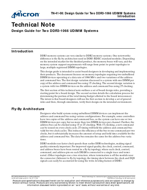
Technical NoteDesign Guide for Two DDR3-1066 UDIMM SystemsIntroductionDDR3 memory systems are very similar to DDR2 memory systems. One noteworthydifference is the fly-by architecture used in DDR3 JEDEC-standard modules. Dependingon the intended market for the finished product, the memory buses will vary, and thememory system support requirements will range from point-to-point topologies tolarge, multiple registered DIMM topologies.This design guide is intended to assist board designers in developing and implementingtheir products. The document focuses on memory topologies requiring two unbufferedDIMM devices operating at a data rate of 1066Mb/s and two variations of the addressand command bus. The first design variation discussed is a system with one DIMM percopy of the address and command bus using 1T clocking. The second design variation isa system with two DIMM devices on the address and command bus using 2T clocking.The first section of this technical note outlines a set of board design rules, providing astarting point for a board design. The second section details the calculation process fordetermining the portion of the total timing budget allotted to the board interconnect.The intent is that board designers will use the first section to develop a set of generalrules and then, through simulation, verify their designs in the intended environment.Fly-By ArchitectureDesigners who build systems using unbuffered DIMM devices can implement theaddress and command bus using various configurations. For example, some controllershave two copies of the address and command bus, so the system can have one or twoDIMM devices per copy, but no more than two DIMM devices per channel. Further, theaddress bus can be clocked using 1T or 2T clocking. With 1T clocking, a new commandcan be issued on every clock cycle; 2T timing will hold the address and command busvalid for two clock cycles. This reduces the efficiency of the bus to one command per twoclocks, but it substantially increases the amount of setup and hold time available for theaddress and command bus. The data bus remains the same for the address bus varia-tions.DDR3 modules use faster clock speeds than earlier DDR technologies, making signalquality extremely important. For improved signal quality, the clock, control, command,and address buses have been routed in a fly-by topology, where each clock, control,command, and address pin on each DRAM is connected to a single trace and termi-nated. (Other topologies use a tree structure, where termination is off the module nearthe connector.) Inherent to fly-by topology, the timing skew between the clock and DQSsignals can easily be accounted for using the write-leveling feature of DDR3.PDF: 09005aef83a0af6b/Source: 09005aef83657fb2 Micron Technology, Inc., reserves the right to change products or specifications without notice. tn4108_ddr3_design_guide.fm-Rev. B 1/11 EN©2009 Micron Technology, Inc. All rights reserved.The address, command, and control signals are routed on the module with fly-by archi-tecture. As illustrated throughout this technical note, the input signal lines are termi-nated on the module, and further termination is not required. For example, as shown inFigure1 and Figure2 on page3, the V TT terminating resistors are at the end of the fly-bychannel.Figure 1: DDR3-1066 Two-UDIMM Topology – 1T Address and Command BusFigure 2: DDR3-1066 Two-UDIMM Topology – 2T Address and Command BusNote that a timing skew exists between the DRAM controller and the various DRAMdevices on the DIMM, and the DRAM controller must account for the timing skews.DDR3 modules support write leveling, which is intended to help determine the timingskews. For an in-depth discussion of write-leveling features, refer to Micron’s DDR3 datasheets that discuss write leveling.DDR3 Signal GroupsThe signals that compose a DDR3 memory bus can be divided into four unique groups,each with its own configuration and routing requirements.•Data group: Data strobe DQS[8:0], data strobe complement DQS#[8:0], data maskDM[8:0], data DQ[63:0], and check bits CB[7:0] (x72)•Address and command group: Bank addresses BA[2:0]; addresses A[15:0]; andcommand inputs, including RAS#, CAS#, and WE#•Control group:Chip select S#[3:0], clock enable CKE[3:0], on-die terminationODT[3:0], and RESET#0•Clock group: Differential clocks CK[3:0] and CK#[3:0]Board StackupA two-DIMM DDR3 channel can be routed on a four-layer board. The layout should usecontrolled impedance traces of Z O = 40Ω (±10%) characteristic impedance. An exampleboard stackup is shown in Figure3 on page4. The trace impedance is based on a 5-mil-wide trace and 0.5oz copper (Cu) with a dielectric constant of 4.2 for the FR4 prepregmaterial. For this stackup, it is assumed that the 0.5oz Cu on the outer layers is plated fora total thickness of 2.1 mils. Other solutions exist to achieve a 40Ω characteristic imped-ance, so board designers should work with their PCB vendors to specify a stackup.TN-41-08: Design Guide for Two DDR3-1066 UDIMM SystemsDDR3 Command and Address Voltage Margin and Slew Rate Figure 3: Sample Board StackupDDR3 Command and Address Voltage Margin and Slew RateThe primary difference between DDR2 and DDR3 module command, address, andcontrol signals is fly-by topology with impedance matching. Impedance matching isrequired for proper fly-by operation.With a single DIMM placed at the end of the motherboard bus, the system is matchedthroughout. The driver impedance could be as much as 40Ω, but is generally set a littlelower; the motherboard is routed at 40Ω; and the DIMM lead-in, which is about 4 inches,is routed at 40Ω. DRAM-to-DRAM routing is 60Ω, but when the additional capacitanceof the DRAM devices is taken into account, this lead-in becomes an effective 40Ωimpedance. The termination resistor to V TT is 39Ω. This configuration provides fast slewrates and clean edge transitions due to the minimal number of reflections.For configurations with 2 DIMMs on a channel, a mismatch occurs at the first DIMM.This mismatch will look like 20Ω impedance and there will be a reflection toward thedriver. If the driver impedance is 40Ω, the reflection will terminate at the controller.When the signal sees the 20Ω impedance, the amplitude drops by about 50%. After thefirst DIMM, the impedances are matched, and there will be little reflection from thetermination.Thus the primary effect of using a second DIMM is mostly amplitude reduction. Therewill also be a slight timing shift and some slew rate change. The slew rate change is dueto the amplitude change, not a rise-time change. Rise time is based on a percentage ofthe total swing, whereas slew rate is based on the amplitude change.The following figures provide examples of the slew rate change for a two-DIMM deviceversus a one-DIMM device. The slew rate changes are primarily associated with theamplitude change due to voltage division rather than the capacitive loading that domi-nated in DDR2. Figure4 shows the waveform for the third DRAM on a single DIMM;Figure5 compares the waveform for the third DRAM on the first DIMM of a two-DIMMdevice and the waveform for the third DRAM on the second DIMM of a two-DIMMdevice.Figure 4: U3, SR, 1T at 1066Figure 5: U3, DR, 1T at 1066Rank 1Rank 0Address and Command Signals for 2T ClockingOn a DDR3 memory bus, the address and command signals are unidirectional signalsdriven by the memory controller. The address and command signals are captured at theDRAM using the memory clocks. For a system with two unbuffered DIMM devices perchannel, signaling differs from that of a device with one unbuffered DIMM per channel.This difference is illustrated in Figure4, compared with Figure5 on page5 and Figure6on page6. The reduced slew rate makes it difficult, if not impossible, to use 1T timingand meet the setup and hold times at the DRAM.To address this issue, the controller can use 2T address timing—increasing the timeavailable for the address command bus by one clock period, as shown in Figure6. ForDDR3-1066, using 2T on the address and command signals, the address and commandbus runs at a maximum fundamental frequency of 266 MHz.Note that S#, ODT, and CKE timings do not change between 1T and 2T addressingbecause they carry only half of the load carried by the other command signals.Figure 6: U3, DR, R0, 2T at 10662T Address and Command Routing RulesIt is important to reference address and command lines to a solid power plane or to aground plane, preferably to a solid V DD power plane. V DD is the 1.5V supply that alsosupplies power to the DRAM on the DIMM. On a four-layer board, the address andcommand lines are typically routed on the second signal layer and referenced to a solidpower plane. The system address and command signals should be power referencedover the entire bus to provide a low-impedance current return path.DDR3 unbuffered DIMM devices also reference the address and control signals to V DD tomaintain the power reference onto the module. The address and command signalsshould be routed from the controller to the first DIMM, away from the data groupsignals. Because address and command signals are captured at the DIMM using theclock signals, they must maintain a length relationship to the clock signals at the DIMM.Unlike DDR2, where external V TT termination resistors are required, DDR3 modulesincorporate on-board V TT termination resistors, as shown in Figure7. This change wasadded to support fly-by architecture. All inputs, including the clock, have fly-by topolo-gies; the data bus pins are directly connected to the DRAM controller. A possible designconsideration would be to vary the topology shown in Figure 7 by bringing the addressand control busses as far as the length B + C/2 and tie-off to each DIMM from the C/2point.Figure 7: DDR3 Address and Command Signal Group 2T Routing TopologyTable 1: Address and Command Group 2T Routing RulesLengthA = Obtain from DRAM controller vendor (“A” is the length from the die pad to the ball on the ASI C package)B = 1.9 to 4.5 inchesC = 0.425 inchesTotal: A + B + C = 2.5 to 5.0 inchesLength Matching±20 mils of memory clock length at the DIMM1TraceTrace width = 5 mils: target 40Ω impedanceTrace space = 12 to 15 mils, reducing to 11.5 mils between the pins of the DIMMTrace space from DIMM pins = 7 milsTrace space to other signal groups = 20 to 25 milsNotes: 1.This value is controller-dependent.Parallel/Pull-Up Resistor (V TTR) Termination ResistorThe V TT supply is still required on the motherboard. However, the external paralleltermination resistors required for DDR2 are not required for DDR3 JEDEC-compliantmodules; the V TT terminating resistors are built onto the module.Address and Command Signals for 1T ClockingOn a DDR3 memory bus, the address and command signals are unidirectional signalsdriven by the memory controller. The address and command signals are captured at theDRAM using the memory clocks. For a system with two unbuffered DIMM devices perchannel, the signaling differs from a device with one unbuffered DIMM per channel (seeFigure4 through Figure6 starting on page5). The reduced slew rate makes it difficult, ifnot impossible, to use 1T timing and meet the setup and hold times at the DRAM.To address this issue, the controller can use 2T address timing—increasing the timeavailable for the address command bus by one clock period, as shown in Figure6.To increase the timing margin, loading on the address and command bus must bereduced. Some controllers provide two copies of the address and command bus. Onecopy is connected to each DIMM, effectively reducing the total maximum load on thebus to one DIMM. With reduced loading, the timing and voltage margin is increased to apoint that 1T address bus timing is generally achievable (see Figure4 on page5).Address and command 1T signal-group routing topology is shown in the block diagramin Figure8 on page9. For DDR3-1066 using 1T on the address and command signals, theaddress and command bus runs at a maximum fundamental frequency of 533 MHz.Adding an extra copy of address and command signals helps improve signaling, but loadreduction alone may not be enough to comply with setup and hold times for 1T signals. 1T Address and Command Routing RulesIt is important to reference address and command lines to a solid power plane or to aground plane.On a four-layer board, the address and command lines are typically routed on thesecond signal layer and referenced to a solid power plane. The system address andcommand signals should be power referenced over the entire bus to provide a low-impedance current return path.The address and command signals should be routed away from the data group signals,from the controller to the first DIMM. Because address and command signals arecaptured at the DIMM using the clock signals, they must maintain the length relation-ship to the clock signals at the DIMM.Figure 8: DDR3 Address and Command Signal Group 1T Routing TopologyTable 2: Address and Command Group 1T Routing RulesLengthA = Obtain from DRAM controller vendor (“A” is the length from the die pad to the ball on the ASI C package)B = 1.9 to 4.5 inchesC = 0.425 inchesTotal: A + B + C = 2.5 to 5.0 inchesLength Matching±20 mils of memory clock length at the DIMM1TraceTrace width = 5 mils: target 40Ω impedanceTrace space = 12 to 15 mils, reducing to 11.5 mils between the pins of the DIMMTrace space from DIMM pins = 7 milsTrace space to other signal groups = 20 to 25 milsNotes: 1.This value is controller-dependent.Setup and Hold DeratingSetup and hold times require derating whenever the slew rate is faster than 1 V/ns. Thederating factors can be obtained from the device data sheet. Slew rates slower than1V/ns generally do not require derating; however, derating can reclaim some timemargin.TN-41-08: Design Guide for Two DDR3-1066 UDIMM SystemsControl SignalsAdditionally, when developing a timing budget, derating the setup and hold times toV REF points is necessary to ensure that all components are using the same timing refer-ence points.Parallel/Pull-Up Resistor (V TTR) Termination ResistorThe external parallel termination resistors that were required for DDR2 are not requiredfor DDR3 JEDEC-compliant modules; the V TT terminating resistors are built onto themodule.Control SignalsThe control signals in a DDR3 system are different from the address signals in severalways. First, the control signals need to use 1T timing. Second, each DIMM rank (alsocalled rank) has its own copy of the control signals. Figure9 on page10 shows a blockdiagram of the topology used for the control signals.The control signals in a DDR3 system differ from the address signals in several ways.First, the control signals use 1T timing. Second, each DIMM rank (also called rank) hasits own copy of the control signals. Control signal-group routing topology is shown in theblock diagram below.Figure 9: DDR3 Control Signal Group Routing Topology ArrayODTLike DDR2, DDR3 supports on-die termination (ODT) signals. For DDR3 modules, ODTprovides more ranges to select from, and also supports dynamic ODT. For a detaileddiscussion of dynamic ODT, refer to Micron’s DDR3 data sheets.In DDR3 devices, ODT signals are used to control the termination of the data group signals. DDR3 does not need the external serial and parallel termination resistors on the data group signals used in earlier DDR systems. The enhanced DDR3 ODT termination scheme terminates signals via internal termination resistors in the DRAM device and in the controller. ODT signals are used to turn termination on or off in the DRAM (ODT is enabled or disabled using the mode registers), depending on the type of bus transition and the system load.ODT SimulationsSimulations were performed to define ODT settings and values. Table 3 on page 11 shows write simulations run with ODT values of 40Ω, 60Ω, and 120Ω for the active slot and 20Ω, 30Ω, and 40Ω for the standby slot. Table 4 on page 12 shows read simulations run with controller ODT values of 60Ω, 57Ω, 150Ω, and 300Ω; and ODT values at 20Ω, 30Ω, 40Ω, 60Ω, and 120Ω.The ODT scheme shown in Table 5 on page 12 provides an alternative method for dual rank (DR) modules. Using dynamic ODT provides tighter ODT control. Simulations showed that up to 20ps of additional margin is possible using dynamic ODT.No single ODT value delivered the best maximum aperture and voltage margin, with the lowest jitter. So the results were reviewed and the best overall value was selected. The ODT values provided in this technical note are only recommendations and provide a good starting point for analyzing a system.For example, two similar designs might use different ODT values based on specificdesign needs; one might need greater voltage margin, the other more timing margin. If a DRAM controller supplier recommends an ODT scheme that differs from thosepresented here, designers should follow the supplier’s recommendation for ODT use.Notes:1.Made possible via dynamic ODT.Table 3:DDR3 ODT Control for Write SimulationsConfiguration Write To DRAM Controller Slot 1Slot 2Slot 1(DIMM 1)Slot 2(DIMM 2)Rank 1Rank 2Rank 1Rank 2Dual rank Dual rank Slot 1ODT off 120ΩODT off ODT off 30ΩSlot 2ODT off ODT off 30Ω120ΩODT off Dual rank Single rank Slot 1ODT off 120ΩODT off 20Ωn/a Slot 2ODT off ODT off 20Ω120Ω1n/a Single rank Dual rank Slot 1ODT off 120Ω1n/a ODT off 20ΩSlot 2ODT off 20Ωn/a 120ΩODT off Single rank Single rank Slot 1ODT off 120Ω1n/a 30Ωn/a Slot 2ODT off 30Ωn/a 120Ω1n/a Dual rank Empty Slot 1ODT off 40ΩODT off n/a n/a Empty Dual rank Slot 2ODT off n/a n/a 40ΩODT off Single rank Empty Slot 1ODT off 40Ωn/a n/a n/a EmptySingle rank Slot 2ODT offn/an/a40Ωn/aNotes:1.Made possible via dynamic ODT.Notes:1.This value is controller-dependent.Table 4:DDR3 ODT Control for Read SimulationsConfiguration Write To DRAM ControllerSlot 1Slot 2Slot 1(DIMM 1)Slot 2(DIMM 2)Rank 1Rank 2Rank 1Rank 2Dual rank Dual rank Slot 175ΩODT off ODT off ODT off 30ΩSlot 275ΩODT off 30ΩODT off ODT off Dual rank Single rank Slot 175ΩODT off ODT off 20Ωn/a Slot 275ΩODT off 20ΩODT off n/a Single rank Dual rank Slot 175ΩODT off n/a ODT off 20ΩSlot 275Ω20Ωn/a ODT off ODT off Single rank Single rank Slot 175ΩODT off n/a 30Ωn/a Slot 275Ω30Ωn/a ODT off n/a Dual rank Empty Slot 175ΩODT off ODT off n/a n/a Empty Dual rank Slot 275Ωn/a n/a ODT off ODT off Single rank Empty Slot 175ΩODT off n/a n/a n/a EmptySingle rankSlot 275Ωn/an/aODT offn/aTable 5: Alternative DDR3 ODT Control for Dual Rank Write SimulationsConfiguration Write To DRAM Controller Slot 1Slot 2Slot 1(DIMM1)Slot 2(DIMM2)Rank 1Rank 2Rank 1Rank 2Dual rankDual rankSlot 1Rank 1ODT off 120Ω1ODT off 30ΩODT off Rank 2ODT off ODT off 120Ω30ΩODT off Slot 2Rank 1ODT off 30ΩODT off 120Ω1ODT off Rank 2ODT off30ΩODT offODT off120ΩTable 6:Control Group Routing RulesLengthA = Obtain from DRAM controller vendor (“A” is the length from the die pad to the ball on the ASI C package)B = 1.9 to 4.5 inchesC = 0.425 inchesD = 0.2 to 0.55 inchesTotal: A + B + C = 2.5 to 6.0 inches Length Matching±20 mils of memory clock length at the DIMM 1TraceTrace width = 5 mils: target 40Ω impedanceTrace space = 12 to 15 mils, reducing to 11.5 mils between the pins of the DIMM Trace space from DIMM pins = 7 milsTrace space to other signal groups = 20 to 25 milsControl Signal Routing RulesSimilar to the address signals, the control signals must be referenced to a solid powerplane or to a ground plane. On a four-layer board, the control signals are typically routedon the bottom signal layer and referenced to a solid power plane. The system controlsignals must be power referenced over the entire bus to provide a Low-Z current returnpath. Unlike address signals, control signals are routed point-to-point from thecontroller to the DIMM.The control signals do not require any series or parallel resistance. The control signalsmust be routed with clearance from the data group signals, from the controller to thefirst DIMM. Because the control signals are captured at the DIMM using the clocksignals, they must maintain the length relationship to the clock signals at the DIMM. Parallel/Pull-up Resistor (V TTR) Termination ResistorThe external parallel termination resistors that were required for DDR2 are no longerrequired with DDR3 JEDEC-compliant modules because the V TT terminating resistorsare built onto the module.Data SignalsIn a DDR3 system, the data is captured by the memory and the controller using the datastrobe (DQS and DQS#) rather than the clock. The data strobe complement (DQS#) mustbe routed as a differential pair with the data strobe (DQS). To achieve the double datarate, data is captured on each crossing point of the DQS/DQS# pairs. Each eight bits ofdata has an associated data strobe (DQS and DQS#) and data mask (DM) bit. Becausethe data is captured off the strobe, the data bits associated with the strobe must belength-matched closely to their strobe bit. This grouping of data and data strobe isreferred to as a byte lane. The length matching among byte lanes is not as tight as it iswithin the byte lane. Figure10 shows the signals in a single-byte lane and the bustopology for the data signals; Table7 shows the data and data strobe byte-lane groups.Figure 10: DDR3 Data Byte Lane Routing and Bus TopologyTable 7: Data and Data Strobe Byte Lane GroupsData Data Strobe Data Strobe Complement Data MaskDQ[7:0]DQS0DQS#0DM0DQ[15:8]DQS1DQS#1DM1DQ[23:16]DQS2DQS#2DM2DQ[31:24]DQS3DQS#3DM3DQ[39:32]DQS4DQS#4DM4DQ[47:40]DQS5DQS#5DM5DQ[55:48]DQS6DQS#6DM6DQ[63:56]DQS7DQS#7DM7C B[7:0]DQS8DQS#8DM8Data Signal Routing RulesIt is important that the data lines be referenced to a solid ground plane. These high-speed data signals require a good ground return path to avoid signal quality degradationdue to inductance in the signal return path. The system data signals should be ground-referenced from the memory controller to the DIMM connectors, and from DIMMconnector to DIMM connector to provide a Low-Z current return path. This is accom-plished by routing the data signals on the top layer for the entire length of the signal. Thedata signals should not have any vias. If this cannot be avoided, then the time delayassociated with the via should be accounted for in the trace length.Table 8: Data Group Routing RulesLengthA = Obtain from DRAM controller vendor (“A” is the length from the die pad to the ball on the ASI C package)B = 1.9 to 4.5 inchesC = 0.425 inchesTotal: A + B + C = 2.5 to 5.0 inchesLength Matching in Data/Strobe Byte Lane±20 mils data strobe, data strobe complement1100 mils for each byte laneLength Matching in Byte Lane to Byte LaneNot required; de-skewing is required because of fly-by topology on the address command busTraceDataTrace width = 7.9 mils: target 40Ω impedanceTrace space = 11.8 mils minimumTrace space from DIMM pins = 7 milsTrace space to other signal groups = 12 milsDifferential StrobeTrace width = 7.9 mils: target 40Ω impedanceTrace space = 4 mils between pairsTrace space to other signals = 15.8 milsNotes: 1.Differential signals have a faster propagation time than single-ended signals. If the datasignals are routed slightly shorter than the data strobe, the data strobe signal will arrive atthe DRAM in the center of its associated data signals. Because the propagation delay canvary with design parameters, simulating these signals is recommended.Clock SignalsThe memory clocks CK[4:0] and CK#[4:0] are used by the DRAM on a DDR3 bus tocapture the address and command data. Unbuffered DIMM devices require two clockpairs per DIMM. Some DDR3 memory controllers drive all these clocks, and othersrequire an external clock driver to generate these signals. This technical note assumesthat the memory controller will drive the four clock pairs required for a two-DIMMunbuffered system. Clocks are not terminated to V TT like the address signals of a DDR3bus. The clocks are differential and must be routed as a differential pair. Each clock pairis differentially terminated on the DIMM. Figure11 on page16 illustrates the routingtopology used for the clocks, but in this example, only one of the two clock pairsrequired per DIMM is shown.Figure 11: DDR3 Clock Signal Group Routing TopologyClock Signal Routing RulesThe clocks are routed as a differential pair from the controller to the DIMM. The clocksare used to capture the address and control signals at the DRAM on the DIMM. As aresult, the clocks must maintain a length relationship to the address and control signalsat the DIMM to which they are connected. Most controllers have the ability to prelaunchthe address and control signals; this feature is used to center the clock in the addressvalid eye. Prelaunching the address and control signals is required because the clocksare loaded lighter than the address signals, and as a result have less flight time from thecontroller to the DRAM on the DIMM. Differentially routed signals also have a shorterflight time than single-ended signals. This effect causes the clock signals to arrive at theDRAM even sooner than the address, command, and control signals; thus, the differen-tial flight time is a little faster than the single-ended signals to the first DRAM based onthe differential coupling. To compensate for the difference in propagation delay, it isrecommended to route the clock signals slightly longer than the address, command, andcontrol signals.TN-41-08: Design Guide for Two DDR3-1066 UDIMM SystemsDDR3 Memory Power Supply RequirementsDDR3 Memory Power Supply RequirementsA DDR3 bus implementation requires three separate power supplies. The DRAM and the memory portion of the controller require a 1.5V supply. The 1.5V supply provides power for the DRAM core and I/O, and at a minimum, the I/O of the DRAM controller. The second power supply is V REF , which is used as a reference voltage by the DRAM and the controller. The third power supply is V TT , the bus termination supply. Table 10 on page 18 summarizes the tolerances for each of these supplies.V REF Voltage and Layout RecommendationsDDR3 supports a separate V REF for address, command, and control pins (V REFCA ) and for the data bus (V REFDQ ). V REFCA and V REFDQ may come from the same power source, but they should be routed to and then decoupled separately at the DDR3 DIMM. Note that the term V REF applies to both V REFCA and V REFDQ .The memory reference voltage, V REF , requires a voltage level of half V DD /V DDQ with the tolerance shown in Table 10. V REF can be generated using a simple resistor divider with 1% or better accuracy. V REF must track half V DD /V DDQ over voltage, noise, and tempera-ture changes. Peak-to-peak AC noise on V REF must not exceed ±2% V REF(DC). To ensure a solid DDR3 design, it is imperative that the V REF noise, including crosstalk, is kept to a minimum.When implementing V REF , consider the following layout recommendations:•Use a 30 mil trace between the decoupling cap and the destination.•Maintain a 15 mil clearance from other nets.•Simplify implementation by routing V REF on the top signal trace layer.•Isolate V REF and/or shield with ground.•Decouple using distributed 0.01µf and 0.1µf capacitors by the regulator, controller, and DIMM slots. Place one 0.01µf and one 0.1µf near the V REF pin of each DIMM. Place one 0.1µf near the source of V REF , one near the V REF pin on the controller, and two between the controller and the first DIMM.Table 9:Clock Group Routing RulesLengthA = Obtain from DRAM controller vendor (“A” is the length from the die pad to the ball on the ASI C package)B = 1.9 to 5.0 inchesB2 = 2.325 to 5.425 inches Length Matching±4 mils for C K to C K#±9.9 mils clock pair to clock pair at the DIMM TraceTrace width = 8 mils: target 40Ω trace impedance, 80Ω differential impedance Trace space = 5 milsTrace space to other signal groups = 20 mils。
航空替代燃料的曙光

车开始使用乙醇燃料和天然气, 但航空燃 油却一直停滞在 Jet-A-1 和 Jet-A 上迟 迟不前。德国科学家 Franz Fischer 和 Hans Tropsch 于 20 世纪 20 年代发明了 将煤炭转变为合成燃油的方法, 用来应对
比例为 50:50 的合成燃油,而且规定合成 燃油的原料可以来自天然气、 煤炭或者生 物等多种资源, 这一认证为发展航空替代 燃料奠定了基础。 美国国防部希望在2011 年以前, 完成所有机型的合成燃油试飞工 作, 并希望在2016年使合成燃油的供应量 占到航空燃油总供应量的一半。 当然, 使 用合成燃油为美国国防部带来的好处不仅 限于减少燃油成本, 还可以降低发动机废 气中的烟尘,提高可 以生产柴油, 柴油正是大量军事装备的血 液。 美国军方的这些试验工作同时为民用 客机使用合成燃油带来了希望的曙光, 美 国空军所使用的合成燃油 (目前是GTL天
航 空 保 障 A VI AT ION S UP P ORT
文 / 王鑫
航空替代燃料的曙光
CTL/GTL synthetic fuel, the dawn of the aviation alternative fuels
界航空业在饱受高油价的威胁以 及环保压力下, 费托法合成燃油 让人们看到了解决问题的曙光。 根据世界石油巨头雪佛龙公司的保守 估计, 2007年全球航空业每天消耗的燃油 多达 6.57 亿升,也就是说,平均每 5分钟 的流量就能够灌满 “水立方” 中的奥林匹 克标准泳池。 Jet-A-1 和Jet-A这两种国 际标准航空燃油从上世纪 50 年代投入使 用以来, 一直作为航空涡轮发动机的最佳 选择。 无论是在天寒地冻的俄罗斯, 还是 在挥汗如雨的科威特, 这两种标号的燃油 在燃烧和润滑品质上都表现出色。 随着油 价和环保问题的日益突出, 越来越多的汽