CV3-1500中文资料
BY459X-1500中文资料
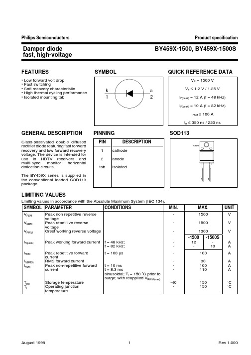
30 IF / A Tj = 125 C Tj = 25 C
20
typ
10
BY459 max
0
0
0.5
1
1.5
2
VF / V
Fig.5. BY459X-1500 Typical and maximum forward characteristic IF = f(VF); parameter Tj
IF / A 30
3 2.5
2.54
0.5
6.4 15.8 max
0.6 2.5
1.0 (2x)
0.9 0.7
Fig.8. SOD113; The seating plane is electrically isolated from all terminals.
Notes 1. Refer to mounting instructions for F-pack envelopes. 2. Epoxy meets UL94 V0 at 1/8".
VF
Forward voltage
IR
Reverse current
CONDITIONS
TYP.
MAX. UNIT
BY459X- 1500 1500S 1500 1500S
IF = 6.5 A IF = 6.5 A; Tj = 125 ˚C VR = 1300 V VR = 1300 V; Tj = 125 ˚C
trr time
Qs I R
25%
100%
Fig.2. Definition of trr and Qs
VCC
Line output transformer LY
Cf
Cs
北京海洋兴业科技 RTC 干体炉产品介绍说明书

新的 RTC 型干体炉(标准干体炉)一台比任何其他产品都更先进的干体炉,一台迄今为止最好的干体炉。
- 低温炉:RTC-156 (-30~155℃) RTC-157(-45~155℃) - 高温炉:RTC-700(33~700℃)作为一台顶级的干体炉,RTC型提供了很多独一无二的功能,例如: - DLC动态负载补偿系统(专利申请中),可确保套管有极佳的温场 一致性- 参考探头配置智能芯片,可实现即插即用 - 可通过USB接口与计算机通讯- 彩色VGA液晶显示屏便于读数和监控温场状态 - 直观、快速和友好的用户界面 - 重量轻,便于携带 - 新式多功能便携式铝箱- 新式多孔套管套件可兼容几乎所有尺寸的传感器 - 外观新颖,更有JOFRA品牌的品质保证 全新RTC干体炉共有三个型号-A型、B型和C型 - RTC-A标准干体炉- RTC-B标准干体炉,自带信号测试接口,可外接参考探 头和DLC探头- RTC-C标准干体炉,可外接参考探头和DLC高精度RTC-156 / RTC-157 精度高达0.04℃ RTC-700精度高达0.11℃ (配外置参考探头时)极佳的稳定性0.005℃(RTC-156 / RTC-157) 0.008℃(RTC-700)超宽的温度范围 RTC156: -30 至 155℃ RTC157: -45 至 155℃ RTC700: 33 至 700℃更好的温度一致性独一无二的双区(RTC-156 / RTC-157)和三区(RTC-700)加热井确保了极佳的温度一致性DLC动态负载补偿功能即使校准大尺寸传感器或者多支传感器时,也能保证套 管内的温场均匀一致(仅B型和C型)温度一致性显示当使用DLC技术时,可以在屏幕上显示套管内温度一致性的状况(仅B型和C型)智能参考探头参考探头配备了智能接头,内置芯片保存了校准数据(温度修正参 数)等信息。
这是一个真正的即插即用校准系统USB通讯所有RTC型干体炉都可以通过USB接口和计算机进行连接通讯效率提升RTC系列可快速加热/制冷,有效提升工作效率RTC-700更具备了超 快冷却技术(专利申请中)EURAMET根据欧洲国家计量协会的EURAMET/cg-13/v.01规范,RTC是现有干 式炉中性能最好的最大…………… 155℃(RTC156/157);700℃(RTC700)最小@环温0℃...-46℃(RTC156);-57℃(RTC157);10℃(RTC700) 最小@环温23℃....-30℃(RTC156);-45℃(RTC157);33℃(RTC700) 最小@环温40℃-15℃(RTC156);-31℃(RTC157);50℃(RTC700)精度(仅B型和C型)带参考探头RTC-156/157 B&C......+0.040C, +0.07℉RTC-700 B&C.....±O.11℃/±0.2℉12个月指标。
NCV1-SP3

46±0.5
+
8.5
64.0 6.5 -HT M + M -HT
༽⌞φ
1.+HT 接测量电压为正时,传感器
+VCC
输出 ISN 为正(ISN 由 M 端流向 0V 端)。 2. 产品二次侧连接线优选屏蔽线, 屏蔽层接近产品端连接线可接机 壳,负电源或电源 0V
A
Rm 0V -VCC
ᆿ㻻㾷≸φ
1. 传感器安装方式一: 2×Φ6.5mm 椭圆孔 推荐使用: 安装固定力矩: 推荐使用: 安装固定力矩: 3. 原边电气连接: 4. 原边固定力矩: 5. 次边电气连接: 次边固定力矩: M6 的螺栓固定 4.5N・m M5 的螺栓固定 3.5N・m M5 的螺栓 2.2N・m M5 的螺栓 ( 或 6.3×0.8 的插头簧片 ) 2.2N・m
ᢝ㺂ḽφ
1. GB/T 25119—2010 轨道交通 机车车辆 电子装置 2. TB/T 2763—2009 机车车辆用电流传感 器和电压传感器
216
ཌᖘተሮφ
112 96
18
30±0.2
51
3-M5
73.5
+
32
M
-
4
138
6.5
+HTБайду номын сангаас
112±0.5 122±0.5
4-Ø5.5
䘔ᯯᕅφ
+HT
2. 传感器安装方式二: 4×Φ5.6mm 圆孔
217
㋴ᓜࣞᘷ৸ᮦφ
1. 基本误差 δi (@VPN,TA=+25℃ ): 3. 零点输出误差 δz (@+25℃ ): 5. 响应时间 Tr (@90% of VPN): ≤ ±1% ≤ ±0.25mA ≤ 4us 2. 线性度误差 δL (@VPN,TA =+25℃ ): ≤ 0.1% 4. 零点温度漂移 δZt (@-40℃ ~+85℃ ): ≤ ±0.75mA
环保型三价白铬电镀工艺
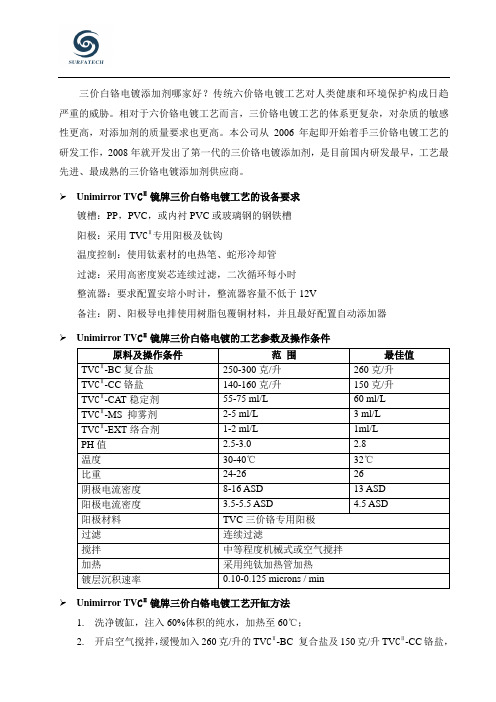
三价白铬电镀添加剂哪家好?传统六价铬电镀工艺对人类健康和环境保护构成日趋严重的威胁。
相对于六价铬电镀工艺而言,三价铬电镀工艺的体系更复杂,对杂质的敏感性更高,对添加剂的质量要求也更高。
本公司从2006年起即开始着手三价铬电镀工艺的研发工作,2008年就开发出了第一代的三价铬电镀添加剂,是目前国内研发最早,工艺最先进、最成熟的三价铬电镀添加剂供应商。
➢Unimirror TV CⅡ镜牌三价白铬电镀工艺的设备要求镀槽:PP,PVC,或内衬PVC或玻璃钢的钢铁槽阳极:采用TV CⅡ专用阳极及钛钩温度控制:使用钛素材的电热笔、蛇形冷却管过滤:采用高密度炭芯连续过滤,二次循环每小时整流器:要求配置安培小时计,整流器容量不低于12V备注:阴、阳极导电排使用树脂包覆铜材料,并且最好配置自动添加器➢Unimirror TV CⅡ镜牌三价白铬电镀的工艺参数及操作条件原料及操作条件范围最佳值TV CⅡ-BC复合盐250-300克/升260克/升TV CⅡ-CC铬盐140-160克/升150克/升TV CⅡ-CAT稳定剂55-75 ml/L 60 ml/LTV CⅡ-MS 抑雾剂2-5 ml/L 3 ml/LTV CⅡ-EXT络合剂1-2 ml/L 1ml/LPH值 2.5-3.0 2.8温度30-40℃32℃比重24-26 26阴极电流密度8-16 ASD 13 ASD阳极电流密度 3.5-5.5 ASD 4.5 ASD阳极材料TVC三价铬专用阳极过滤连续过滤搅拌中等程度机械式或空气搅拌加热采用纯钛加热管加热镀层沉积速率0.10-0.125 microns / min➢Unimirror TV CⅡ镜牌三价白铬电镀工艺开缸方法1.洗净镀缸,注入60%体积的纯水,加热至60℃;2.开启空气搅拌,缓慢加入260克/升的TV CⅡ-BC 复合盐及150克/升TV CⅡ-CC铬盐,搅拌至完全溶解。
注意:加入TV CⅡ-BC复合盐后,镀液温度会急剧下降,必须维持加入以防温度下降导致溶解不彻底。
CV3-1500电压互感器说明书

CV3-1500电压互感器说明书
CV3-1500电压互感器说明书:
一、用途
CV3-1500电压互感器可在高压和超高压电力系统中用于电压和功率的测量、继电保护、自动控制等方面,并可兼作耦合电容器用于电力线载波通信系统。
如有需求,可提供用于谐波电压测量的内部附件及外部接线端子。
二、主要技术性能
1、安装场所:户内或户外。
2、安装运行地区的海拔不超过2000米。
(根据用户要求,可制造海拔2000m以上的高原型CVT)。
3、安装运行地区环境空气温度范围为-40~+40℃。
4、安装运行地区的风速不超过150km/h。
三、性能
1、精度等级:0.
2、0.5、1.0、3.0、3P
2、额定电容:3500-20000Pf
四、执行标准
GB4703-84《CV3-1500电压互感器》及IEC186
五、结构简介
CV3-1500互感器分压器由高压电容器和中压电容器组成,中压端子由瓷套下部侧壁引出,供试验用,该端子通过瓷套引到电磁装置内。
CR1500SA中文资料

190 220 275 320 25 58 65 75 90 120 140 160 190 220 275 320
500
MAXIMUM RATINGS
SUFFIX
SB
Ipp 10x160µs Amps 150
Ipp 10x560µs Amps 100
ITSM 60Hz Amps
30
DI/dt Amps/µs
500
MAXIMUM RATINGS
SUFFIX
SC
Ipp 2x10µs Amps 500
Ipp 10x160µs Amps 200
230A 260A 310A 350A 030B 064B 072B 080B 110B 130B 150B 180B 230B 260B 310B 350B
030C 064C 072C 080C 110C 130C 150C 180C 230C 260C 310C 350C
Reverse Stand-off Voltage
SYMBOL IRM IBO IH
PARAMETER Stand-off Current Breakover Current Holding Current
THERMAL DATA
T stg Storage and Operating Junction Temperature range
Tj
TL
Maximum Temperature For Soldering
Electrical Charecteristics The electrical characteristics of a CRXXXX device is similar to that of a self gated Triac, but the CR is a two terminal device with no gate. The gate function is achieved by an internal current controlled mechanism.
Differential Probes TDP1500 和 TDP3500 数据手册说明书

Differential ProbesTDP1500 and TDP3500 DatasheetDifferential active probes provide truer signal reproduction and fidelity for high-frequency measurements. With ultra-low input capacitance and versatile device-under-test connection capabilities, the TDP1500 and TDP3500 Differential-ended Active probes provide excellent high-speed electrical and mechanical performance required for today's digital system designs.Key performance specifications3.5 GHz (TDP3500) and 1.5 GHz (TDP1500) probe bandwidth ≤1 pF (TDP1500) and ≤0.3 pF (TDP3500) differential inputcapacitance200 kΩ (TDP1500) and 100 kΩ (TDP3500) differential input resistance±25 V (TDP1500) and ±15 V (TDP3500) DC + pk AC input voltage >60 dB at 1 MHz and >25 dB at 1 GHz CMRRKey featuresOutstanding electrical performance3.5 GHz and 1.5 GHz bandwidth models - accurate measurementsfor serial and digital applicationsExcellent common mode rejection – reduces measurement errorsin higher common environmentsLow capacitive and resistive loading – maintains signal fidelity andreduces DC biasing interactionsVersatile mechanical performanceCompact probe head size for probing small geometry circuitelementsDUT attachment accessories enable connection to fine-spacedSMDsRobust design for reliabilityEasy to useConnects directly to oscilloscopes with the TekVPI ™ probeinterfaceProvides automatic units scaling and readout on the oscilloscopesdisplayEasy access to probe comp box controls or oscilloscope probe menu display for probe status, setup control, and diagnosticinformationIntegrated Scope/Probe systemDirect connection to and powered from the TekVPI ™ oscilloscope interface (Connects directly to TekVPI scopes without the need ofan external power supply, like many competitors require)Single-button oscilloscope probe menu accessSetup and control from probe comp box or oscilloscope userinterfaceAutoZero - zeros out output offsetRemote GPIB/USB probe control through the oscilloscopeApplicationsDesign, validation, debugging, and characterization of common high-speed serial bus designs:I 2CCAN/LINSPISerial ATAEthernet (GbE)USB 2.0FIreWire (1394b)Signal integrity, jitter, and timing analysisManufacturing, engineering, and testA better measurement toolSpecifically designed for use and direct connection to oscilloscopes with the TekVPI ™ probe interface, the TDP1500 and TDP3500 Differential probes achieve high-speed signal acquisition and measurement fidelity bysolving three traditional problems:DUT loading effects - Are reduced by lower input capacitance and highinput resistanceDUT connectivity - A variety of accessories exist for attaching to smallSMDs, some come standard or recommendedMaximizing of system (oscilloscope and probe) bandwidth - Probing solutions for all measurements for TekVPI interface oscilloscope models up to 3.5 GHzFor the best probe support, download and install the latest version of the oscilloscope software from /software/downloads .DatasheetTDP1500 and TDP3500 Differential probesSpecificationsAll specifications are guaranteed unless noted otherwise. All specifications apply to all models unless noted otherwise.Warranted characteristicsBandwidth (probe only)TDP1500≥1.5 GHz warrantedTDP3500≥3.5 GHz warrantedAttenuationTDP15001X, 10XTDP35005XCMMR>60 dB at 1 MHz, >25 dB at 1 GHzMaximum input voltage(nondestruct)TDP1500±25 V (DC + pk AC)TDP3500±15 V (DC + pk AC)Typical characteristicsRise time (probe only)TDP1500≤265 psTDP3500≤110 psDifferential input capacitanceTDP1500≤1 pFTDP3500≤0.3 pFDifferential input resistanceTDP1500200 kΩTDP3500100 kΩNoise levelTDP1500<≈Propagation delay 5.4 nsCommon mode input rangeTDP1500±7 V (1X)±7 V (10X)TDP3500+5 V to -4VInput offset rangeTDP1500±7 V (10X or 1X)TDP3500±1 V displayedDifferential input dynamic rangeTDP1500±8.5 V (10X)±850 mV (1X)TDP3500±2 VNominal characteristicsRecommended oscilloscope interfaceTekVPI ™ ProbePower requirementsPower requirementsPowered directly by oscilloscopes with the TekVPI probe interface.Physical characteristicsDimensionsWeight1Typical for TDP1500.2Typical for TDP1500.DatasheetTypical characteristicsTDP1500 and TDP3500 Differential probes Ordering informationModelsTDP1500 1.5 GHz Differential Probe with TekVPI™ Probe Interface, Certificate of Traceable Calibration Standard.TDP3500 3.5 GHz Differential Probe with TekVPI™ Probe Interface, Certificate of Traceable Calibration Standard.OptionsLanguage optionsOpt. L0English manualOpt. L5Japanese manualOpt. L7Simplified Chinese manualService optionsOpt. C3Calibration Service 3 YearsOpt. C5Calibration Service 5 YearsOpt. D1Calibration Data ReportOpt. D3Calibration Data Report 3 Years (with Opt. C3)Opt. D5Calibration Data Report 5 Years (with Opt. C5)Opt. R3Repair Service 3 Years (including warranty)Opt. R5Repair Service 5 Years (including warranty)Opt. SILV900Standard warranty extended to 5 yearsAccessoriesTDP1500 standard accessoriesDatasheetTDP3500 standard accessoriesRecommended accessoriesTektronix is registered to ISO 9001 and ISO 14001 by SRI Quality System Registrar.Product(s) complies with IEEE Standard 488.1-1987, RS-232-C, and with Tektronix Standard Codes and Formats.TDP1500 and TDP3500 Differential probesDatasheetASEAN / Australasia (65) 6356 3900 Austria 00800 2255 4835*Balkans, Israel, South Africa and other ISE Countries +41 52 675 3777 Belgium 00800 2255 4835*Brazil +55 (11) 3759 7627 Canada180****9200Central East Europe and the Baltics +41 52 675 3777 Central Europe & Greece +41 52 675 3777 Denmark +45 80 88 1401Finland +41 52 675 3777 France 00800 2255 4835*Germany 00800 2255 4835*Hong Kong 400 820 5835 India 000 800 650 1835 Italy 00800 2255 4835*Japan 81 (3) 6714 3010 Luxembourg +41 52 675 3777 Mexico, Central/South America & Caribbean 52 (55) 56 04 50 90Middle East, Asia, and North Africa +41 52 675 3777 The Netherlands 00800 2255 4835*Norway 800 16098People's Republic of China 400 820 5835 Poland +41 52 675 3777 Portugal 80 08 12370Republic of Korea +822 6917 5084, 822 6917 5080 Russia & CIS +7 (495) 6647564 South Africa +41 52 675 3777Spain 00800 2255 4835*Sweden 00800 2255 4835*Switzerland 00800 2255 4835*Taiwan 886 (2) 2656 6688 United Kingdom & Ireland 00800 2255 4835*USA180****9200* European toll-free number. If not accessible, call: +41 52 675 3777For Further Information. Tektronix maintains a comprehensive, constantly expanding collection of application notes, technical briefs and other resources to help engineers working on the cutting edge of technology. Please visit . Copyright © Tektronix, Inc. All rights reserved. Tektronix products are covered by U.S. and foreign patents, issued and pending. Information in this publication supersedes that in all previously published material. Specification andprice change privileges reserved. TEKTRONIX and TEK are registered trademarks of Tektronix, Inc. All other trade names referenced are the service marks, trademarks, or registered trademarks of their respective companies.11 Feb 2016 51W-20565-6 。
RCP1500G03

1750 -3.04
1800 -3.12
1850 -3.22
1900 -3.34
1950 -3.47
2000 -3.62
Out [dB]
-2.9 -3.02 -3.12 -3.21 -3.28 -3.37 -3.44 -3.49 -3.52 -3.55 -3.56 -3.55 -3.54 -3.51 -3.48 -3.42 -3.35 -3.28 -3.18 -3.09 -2.99
[MHz] [dB]
1000 -3.49
1050 -3.35
1100 -3.24
1150 -3.15
1200 -3.08
1250
-3
1300 -2.95
1350 -2.91
1400 -2.88
1450 -2.86
1500 -2.86
1550 -2.87
1600 -2.89
1650 -2.93
1700 -2.98
Return Loss [dB]
[dB] [degree] [dB]
S11 S22
S33 S44
±0.30 -90.06 -21.83 -21.53 -22.12 -22.01 -21.8
±0.16 -90.23 -22.26 -22.14 -22.9 -22.88 -22.39
±0.06 -90.34 -22.7 -22.79 -23.52 -23.67 -22.99
2. Electrical Specification
Freq.
(MHz)
1000 - 2000 VSWR
Max
1.2
Amplitude Balance
max (dB)
± 0.50 Phase
- 1、下载文档前请自行甄别文档内容的完整性,平台不提供额外的编辑、内容补充、找答案等附加服务。
- 2、"仅部分预览"的文档,不可在线预览部分如存在完整性等问题,可反馈申请退款(可完整预览的文档不适用该条件!)。
- 3、如文档侵犯您的权益,请联系客服反馈,我们会尽快为您处理(人工客服工作时间:9:00-18:30)。
Voltage Transducer CV 3-1500
For the electronic measurement of voltages : DC, AC, pulsed...,with a galvanic isolation between the primary circuit (high voltage)and the secondary circuit (electronic circuit).
Electrical data
V PN Primary nominal r.m.s. voltage 1000
V V P Primary voltage, measuring range 0 .. ± 1500V V S Secondary analog voltage @ V P max 10
V K N Conversion ratio 1500 V / 10 V R L Load resistance ≥ 1k ΩC L Capacitive loading ≤ 5nF V C Supply voltage (± 5 %)± 15
V I C Current consumption
32 + V S / R L mA V d R.m.s. voltage for AC isolation test, 50 Hz, 1 mn
6kV V e
R.m.s. voltage for partial discharge extinction @ 10 pC
2
kV
Accuracy - Dynamic performance data
Typ
Max X G Overall accuracy @ V P max T A = 25°C ± 0.2%- 40°C .. + 85°C
± 0.6%V O
Offset voltage @ V P = 0
T A = 25°C ± 5.0mV - 40°C .. + 85°C
± 13.0
mV t r Response time 1) @ 90 % of V P max 0.4
µs dv/dt dv/dt accurately followed 900
V/µs f Frequency bandwidth (- 1 dB) @ 33 % of V PN
DC .. 800
kHz
General data
T A Ambient operating temperature - 40 .. + 85°C T S Ambient storage temperature - 45 .. + 90°C P Total primary power loss 2.8W R 1Primary resistance 360k Ωm
Mass
560
g
Standards 2)
EN 50155
Notes :
1)With a dv/dt of 900 V/µs
2)
A list of corresponding tests is available
Features
•Closed loop (compensated) voltage
transducer
•Insulated plastic case recognized according to UL 94-V0•Patent pending.
Advantages
•Excellent accuracy •Very good linearity •Low thermal drift •Low response time •High bandwidth
•
High immunity to external interference
•Low disturbance in common mode.
Applications
•AC variable speed drives and servo motor drives
•Static converters for DC motor drives •
Uninterruptible Power Supplies (UPS)
•Power supplies for welding applications
•
Railway overhead line voltage measurement.
V PN =1000 V
030129/7
LEM Components
Mechanical characteristics
•General tolerance ± 0.3 mm
•Transducer fastening
3 holes ∅ 5.5 mm 3 M5 steel screws Fastening torque max
4 Nm or 2.9
5 Lb. - Ft.•Connection of primary M5 threaded studs •Connection of secondary M5 threaded studs •Fastening torque max
2.2 Nm or 1.62 Lb. -Ft.
Dimensions CV 3-1500 (in mm. 1 mm = 0.0394 inch)
Remarks
•V S is positive when V P is applied on terminal +HT.•CEM tested with a shielded secondary cable.
Shield connected to 0 V at both ends, or disconnected.•This is a standard model. For different versions (supply voltages, turns ratios, unidirectional measurements...),please contact us.
LEM reserves the right to carry out modifications on its transducers, in order to improve them, without previous notice.。