ED29M52R40T60中文资料(Positronic)中文数据手册「EasyDatasheet - 矽搜」
夏米尔慢走丝290-500操作说明书
夏米尔慢走丝操作说明书1.目的为正确操作线切割设备以维持线切割设备之精度及稳定性,延长其使用寿命,使线切割加工作业规范.标准化,而达到提升质量保证,提升加工效率的目的,以满足客户需求.2.适用范围适合于ROBOFIL290.ROBOFIL500型号之慢走丝.3.作业内容3.1 开机当电柜合闸通电的时候,数控恢复断电前的状态.如果想装软件,必须启动特别的启动屏幕,步骤如下:3.1.1 按通电开关.3.1.2 同时,按住控制板上任何一个键,直到显示启动屏幕.3.1.2.1 监控功能(MONITOR)是保留给CT维修服务人员的.3.1.2.2 装入功能(LOAD)用来装软件模块:系统.自诊断.3.1.2.3 初始化功能(INITALIZE)数控返回到初始状态(相当于装入软件的状态).3.1.2.4 继续功能(CONTINUE)用于退出特别启动屏幕,进入正常操作(象上面的操作一样,激活最后一个屏幕).3.2 安装软件3.2.1 系统软件一旦初始化菜单被激活,接着:* 把系统盘(磁盘A)插入驱动器A* 选择LOAD(F2)在装软件期间,磁盘驱动器二极管和屏幕右一指灯亮,数控显示装入过程的信息.装入结束后,NC在EXE方式下,以便执行装入下列文件的操作.(语言,CT-EXPERT.CAM-CT)3.2.2. 装入系统软件后,显示语言配置菜单:* 指明所需要的语言名,用RETURN确认* 根据指示插入所选择的语言盘* 按F1(寻找)输入必须的文件,设备即按所选语言配置.3.3 屏幕组织* 准备模式(PREPARATION) 符号: PREP 背景色: 绿色* 执行模式(EXECTION) 符号: EXE 背景色: 紫色* 信息模式(INFORMATION) 符号: INFO 背景色: 蓝色* 图形模式(GRAPIC) 符号: GRAPH 背景色: 橙色3.3.1 PREP 准备方式3.3.1.1 编辑器(EDITOR)该功能用来建立或修改ISO程序,控制程序PROFIL程序1): 寻找文本(FIND.TEXT)2): 寻找下一个(FIND NEXT)3): 块(BLOCK)4): 标记范围开始(MARK START>标记范围结束(MARK END)5): 保存文件(SAVE FILE)6): 退出(EXIT)3.3.1.2 CAM-CT* 准备ISO零件程序需要交替运用菜单功能与绘图功能.<此单节介绍略>3.3.1.3 专家系统(CT-EXPERT)* 这些程序可以手工或者由CT-EXPERT专家系统自动生成.* 与不使用CT-EXPERT专家系统相比,CT-EXPERT生成的TEC文件是分完整的.用一个TEC文件,一个ISO文件和一个命令文件就可能执行个加工操作.相反,当一个文件在CT-EXPERT中查询或者修改时,必须3.3.1.4 文件(FILES)* 本功能用于处理存储在(所用的)不同单元上的所有文件(选择一个单示其下的文件目录).* 可以对给定目录中的文件操作,或者从一个目录转到另一个目录.1): 拷贝(COPY)2): 删除(DELETE)3): 改变名称(RENAME)4): 显示(DESPLAY)5): 打印(PRINT)6): 转换单元(CHANGE UNIT)7): 格式化(INITIALISE)8): 退出(EXIT)3.3.1.5 表编辑(EDIT TABLES)1): TEC--规准表(工艺文件的定义)2): OFS--偏移量(补正量)3): VAR--变量(变量值代入)4): WIR--电极丝(使用线参数)3.3.2. EXECUTION执行方式* 配置机台* 调节多种参数* 运行测量功能* 在开始加式操作之前,执行所需要的测试3.3.2.1. 执行程序(PROGRAM EXECUTION)1). 切割(CUT)2). 空跑(DRY RUN)3). 检验(VERIFY)4). 绘图(DRAW ON SCREEN)5). 改变模式(CHANGE UNIT)3.3.2.2. 用户参数(USER PARAMETERS)1) HPA: 工件设度2) CLE: 补偿间隙3) SCF: 比例系数4) ROT: 工件旋转5) TFE: 补正量认可6) TRE: 斜度认可7) MIR,X: X镜像8) MIR,Y: Y镜像9) ZID: 下导头至平台距离10) ZSD: 上导头至工件顶部距离11) BLK: 单节执行12) CBC: 一个命令一个命令执行13) SIM: 加工与空跑转换14) TSIM: 模拟穿丝15) VSIM: 空跑速度16) BLD: 遇"/"跳过17) OSP: 选择性暂停18) ENG: 选择单位19) COE: 遇不错误继续执行20) ART: 断电后自动重启动21) ATH: 断丝后重穿丝22) CHRA: 选择表面精度的单位23) WIRE LN : 电极丝的消耗量24) MIOL: 测量允许的误差25) DVI: 缺省使用的源外设26) EXT: 缺省扩展27) DEIO: 电介液的导电率28) ATT: 开始切入路径的长度29) EAO: 遥控报警3.3.2.3: 电源参数(GENERAO PARAMETERS)* EL: 使用的电极丝号* PA: 工件的材料号1) FF: 暂时降低频率2) M : 切割方式3) V : 切割电压4) A : 脉冲宽度(放电时间)5) B : 休止时间6) S : 最大进给率7) AJ: 伺服基准平均电压8) TAC: 短脉冲时间9) IAL: 点火脉冲电流10) WS: 走丝速度11) WB: 线张力12) INJ: 水压13) ST: 保护策略3.3.2.4: 作图参数(DRAWING PARAMETERS) <略>3.3.2.5: 激活表(ACTIVE TABLES)1). TEC: 工艺表2). OFS: 补正值表3). VAR: 变量表4). PNT: 点表5). WIR: 电极丝准备表3.3.2.6: 测量(MEASURING)测量功能用于执行一系列操作,这些操作分成两类.* 机台调校测量* 电极丝相对于被加工工件位置的测量* 电极丝相对于被加工工件位置的测量1).找外轮廓中心(EXTERNAL CENTERING)2).找中心平面(MIDDLE) (寻沟槽)3).找拐角(CORNER)4).测角度(ALIGN ADGE)5).校孔ALIGN HOLES6).找边EDGE7).电极丝校垂直VERTICAL ALIGNMENT8).找中心CENTER9).工件校垂直PART ALIGNMERNT10).测ZID GUIDES SETUP11).喷嘴调节NOZZLE ADJUST12).垂直返回VERTICAL RETURN13).工件返回PART RETURN注意:1).一定要在加工状态下执行测量功能,例如,上导向器在低位置(工作位置),丝的张力正确(张力已校准,并且WB=精加工张力).水的离子浓度合适(即水电阻率要求范围)并保持恒温.2).被加工工件必须除油,去磁,去毛刺.3).每周一次,或者在每次加工高精度,斜度加工之前,特别是拆卸导向器后,要执行电极丝导向器设定功能.4).确信使用的电接触类型与所用电极丝的类型一致.5).开始测量前,要确认电极丝没有与被测量物短路.3.3.2.7. 手动(MANUAL)1).接触激活/不激活动力(TOUCH ACTIVE)2).返回断线点或轮廓(RETURN CONTOUR)3).电源参数(GENERATOR PARAMETERS)4).点动/连续方式(INCRE MENTAL MODE)5).接通/断开接触(SWITCH OFF CONTACT)6).激活/不激活(SWITCH OFF JET)7).软极限(SOFT LIMITS)3.3.2.8. 基准点(REFERENCE)机台配置的光栅尺每10MM有一个基准标记,任何一个基准标记都可以用来决定坐标轴的基准位置.3.3.2.9 服务(SERVICE)1).日期和时间(DATE HOUR)2).周期(CYCLES)3).语言(LANGUAGE)4).安全(SECURITY)3.3.3. INFO查询模式* 它汇集了所有涉及到机台配和加工操作监视的信息.3.3.3.1 观察画面(SURVEY)1). 机台坐标系(MACHINE)2). 工作坐标系(PART)3). 速度(SPEED)4). 压力(PRESURE)5). 去离子(DEIO)6). DO=0.000(补正值)3.3.3.2 加工画面(MACHINING)3.3.3.3 运行程序画面(RUNNING PROGRAMS)3.3.3.4 信息画面(MESSAGES)3.3.3.5 模态状况画面(MODAL STATE)3.3.3.6 空白画面(BLANK)3.3.3.7 参考点画面(REFERENCE)3.3.3.8 输入输出画面(INPUTS-OUTPUTS)3.3.3.9 断丝点画面(BREAKAGE POINTS)3.3.3.10 参考点画面(REFERENCE)3.3.3.11 输入输出画面(INPUTS-OUTPUTS)3.3.3.12 断丝点画面(BREAKAGE POINTS)3.3.3.13 服务画面(SERUICE)3.4 GRAPHIC 图形方式图形方式有一个图形页面,用于在操作者定义的平面上执行一个工件程序期间,在屏幕上显示电极丝行经的轨迹.3.5 常用命令词:3.5.1 CTA:用于机床坐标系的绝对加工移动.3.5.2 CTR:用于机床坐标系的相对加工移动.3.5.3 CPA:用于工件坐标系的绝对加工移动.3.5.4 CPR:用于工件坐标系的相对加工移动.3.5.5 GOH:用于移动Z轴,并根据新的工件高度H定位上导向器喷嘴的位置.3.5.6 GOP:把机床各轴移动到用SEP命令储存的点位.3.5.7 MOV:在机床坐标系中移动到所选定的数值.3.5.8 MVR:在机床坐标中相对移到所选定的数值.3.5.9 MPA:在工件坐标中移动到所选定的数值.3.5.10 MPR: 在工件坐标中相对移动到所选定的数值.3.5.11 REX:从当前规准表中取规准,传输给加工电源,参数根据工件高度H设定.3.5.12 SEP:点记忆.3.5.13 ZCL:时间计数器清靃.3.5.14 SMA:设定机床坐标系的X轴和Y轴坐标.3.5.15 SPA::设定工件坐标系的X轴和Y轴坐标.3.5.16 SPG:用来执行一个工件程序文件.3.5.17 TEC:用于选择含有即将使用的工艺规准表文件.3.5.18 CLS:清屏幕显示的图形页.3.5.19 CPY:用于拷贝原文件到另一前设,可以换名字.3.5.20 DLF:删除文件.3.5.21 LOOP:返回命令程序起点,并执行一定次数.3.5.22 SWA:存储电极丝按工作表面手动校直位置.3.6 加工前检查清单:3.6.1«电介液»功能检查:3.6.1.1过滤:确认过滤网压力表读数是否在设定范围,观察导电块冷却区是否有水浸泡.3.6.1.2 去离子度:15±2U.CM3.6.1.3 温度:20±0.53.6.2«腐蚀»功能的检查:3.6.2.1 导电块:是否被水浸泡,表面磨损情况及安装质量.3.6.2.2 接地电缆和编织线:各电缆连接是否牢固.3.6.3 «电极丝更换»的检查:3.6.3.1 丝的种类(直径.材料)3.6.3.2 走丝是否正常3.6.3.3 如果安装新的丝轴,检查丝轴的质量.丝是否有氧化.3.6.3.4 丝的校直和退火.3.6.4工件安装检查:3.6.4.1 夹治具的清洗.3.6.4.2 工件去毛刺.清洁.3.6.4.3 工件装夹.3.6.4.4 工件的调整.3.6.5参数调整和检查:3.6.5.1 绝对参考点找取.3.6.5.2 在更换(重新装)导向器之后,进行«导向器»设定循环.3.6.5.3 在更换喷嘴或更换导向之后,运行«喷嘴调节»过程.3.6.5.4 如果没有在命令程序内设定丝参数,就要在程序一开始加入该设定.3.6.5.5 在«EXE»方式下检查«用户»和«电源»参数什是否在工件切割时要求的参数值.3.6.5.6 在丝准备表内选择丝文件.(.WIR)3.6.5.7 选择需要的工艺文件.(.TEC)3.6.5.8 选择用户偏移文件.(USER.OFS)3.6.6程序运行.3.6.7开始切割.。
S-29多功能测量仪产品说明书

S-29RangesBenchtop Recorders10-Color, 20 Input HybridDR130 Series Starts at$ߜHigh-Speed Scanning and RecordingߜTen-Color Recording ߜThermocouple, RTD, Voltage InputsߜOptional Floppy Drive for Data Storage ߜEasy-to-Carry,Lightweight DesignSpecificationsNumber of Inputs: Up to 10 or 20 points A/D Resolution:±20,000Reference Junction Compensation Error:±1°C (1.8°F) (R, S, B, C, W),±0.5°C/0.9°F (K, J, T, E, N, U, L CHROMEGA ® vs. Au7% Fe)Scan Cycle Time:2 to 60 sec selectable (2, 3, 4, 5, 6, 10, 12,15, 20, 30, 60 sec)A/D Integration Time:20 msec (50 Hz), 16.7 msec (60 Hz), and100 msec (10 Hz), (50/60 Hz) selectable Input Impedance:>10 M Ω on 2V or lower ranges and T/C; approx. 1 M Ω on 6V or higher rangesInput Bias Current:<10 nAThermocouple Burnout Protection:ON or OFF selectable for each channel Temperature Coefficient:Zero drift;0.01% of range/°C, full span; 0.01% of range/°CMax Input Voltage:±10 Vdc (60V on 6V or greater ranges)Common Mode Voltage:250 Vrms AC (50/60Hz)DR130-12-1, $4970.*Refer to footnote on page S-30 for CE ordering information.W i r e l e s sC o n v e r s i o n R e c e i v e r sA v a i l a b l e . F or D e t a i l sV i s i t o m e g a .c om /m w t c -r e c 6DISCONTINUEDDISCONTINUEDThe OMEGA ®DR130 Series portable hybrid recorder offers high speed scanning of 20 points/2 sec and high speed recording. This versatile recorder weighs less than 10 kg (21 lb).Operation is simple, yet powerful optional computing functions and floppy disk enhance the units performance. The DR130 uses a high breakdown voltage solid state relay that permits high scan speed and long relay life without noise.DISCONTINUEDDISCONTINUEDDR130 Series display, shownsmaller than actual size.All units may have display with °F/°C and 50 Hz option field selectable.Only 1 communications option per unit. Other options can be combined as required. Floppy drive units include free conversion software.* For CE option add suffix “-CE ” to model number and $380to price.Ordering Examples: DR130-12-2-C2,hybrid recorder with RS232 interface, plus DR130-ZFP-10,paper, plus DR130-RC,replacement 10-color printing ribbon, $6524 + 18 + 29 = $6571.OCW-3, OMEGACARE SM extends standard 2-year warranty to a total of 5 years ($350), Common Mode Rejection:120 dB (50 or 60 Hz ±0.1%)Normal Mode Rejection:40 dB (50 or 60 Hz ±0.1%)Max Between Chan:150 Vrms AC (50/60 Hz except RTD)PrintoutPrinting Technique:Raster scan using a wire-dot printer and 10-color ribbon Effective Recording Span:150 mm (5.9"), analogChart:Z-fold chart, 230 mm W x 20 m L (9" x 65.5')Recording Resolution:±0.1 mm Recording Accuracy:Measurement accuracy plus (±0.2% of effective recording span)Printout Format:Analog trend/analog trend plus digital data logging Chart Speed:1 to 1500 mm/hr Chart Drive:Pulse motor drive Chart Speed Accuracy:±0.1%Recording Modes:Normal, print on alarm, chart speed/interval changes at set alarmStandard Printing Functions:Engineering units (up to 6alphanumerics), tag number (up to 7 alphanumerics), alarms (channel number, alarm types, and the time of alarm On/Off),scale markings (0/100%, 0/50/100%, or 20% steps), program list, manual,message (max 16 characters), and header (60 characters x 5 lines)Display and ControlsDisplay:5 x 7 dot matrix, 3 row,vacuum fluorescent; 1st row 22 large,2nd and 3rd 40 small characters Data Display:Measured data (tag number, channel number, alarm status,measured value, engineering unit), bar graph, clock, alarm status, relay status,programming data, battery status, and recording format (trend/log)Scaling Range:-30,000 to 30,000Calculation:Difference between any channels or moving average for every 2 to 64 scansInternal Memory:10-yr lithium battery back up; 512 KB SRAM with floppy disc drive option Optional Memory:3.5 inch floppy; 1.4 MB or 720 K Alarms:Up to 4-channelOutputs:12 max with -A4 and -R1 opt Alarm Types:High (H), low (L), high rate of change (RH), low rate of change (RL), delta high (D H) and delta low (D L)Recording:Trend Mode:CH# alarm types, and on/off times in the right marginLogging Mode:CH# and alarm types at the start of measured dataAlarm Acknowledgement:Pressing the ACK key stops the alarm display flashing and resets the dedicated common relay outputAlarm Reset:Hold type relay output by pressing the RESET keyDisplay:Flashing display can be obtained for 20 point alarm status (channels 1 to 20) plus one common point for computing channels (channels 31 to 60)GeneralAmbient Operating Temperature:5 to 40°C (40 to 104°F)Humidity Range:20 to 80%Power Supply:90 to 250 Vac, 50 or 60 Hz ±2%Power Consumption:Approx 130 VA Clock:With calendar function Input Terminals:Clamped input terminal block (standard) and screw input terminal block (optional)Mounting:Desktop or flush panel mounting (can be inclined up to 30° backward from vertical)Dimensions:221 H x 338 W x 335 mm D (83⁄4x 135⁄16x 133⁄16") Weight:9.3 kg(20.5 lb) approxOptional FeaturesAlarm Outputs (-A4 option):10 points,contact rating 30 Vdc or 250 Vac, 2 A resistive; AND, OR, REFLASH, or latching option type outputRemote Control (-R1 Option):Through the contact input, start/stop, chartspeed/interval change, manual printout,message recording, digital recording in the trend mode, writing on the memory card, and loading trigger available; input signal; TTL-level, open collector, and contact status, plus 2 alarm outputs GPIB Interface (-C1 Option):conforms to IEEE standard 488-1978RS232C Interface (-C2 Option):conforms to EIA RS232CComputation (-M1 option):Functions:+, -, x, =, SQR (square root), ABS (absolute value), LOG (common logarithm), EXP (exponential), logic (AND, OR, NOT, XOR), CLOG andTLOG (group or channel; max, min, avg,totals, max, minus, min)Software: Runs on Windows ®95, 98 or NT 4.0OMEGACARE SM extended warranty program is available for models shown on this page.OMEGACARE SM covers parts, labor, and equivalent loaners. Ask your salesrepresentative for full details when placing an order.。
德图400说明书
÷
更换打印纸
纸盒位于打印机的顶部。如图所示装好打印纸。 注:打印纸为热敏打印纸,也就是说只能单面打印。因 此注意正确地安装纸方向 把开关切换到“进行”即可转动纸卷
在接有舒适度探头(0628 0009)的情况下计 算紊流度 该功能键被冻结 在接有 CO 探头情况下,重复校零
- 10 -
Aw 值
NET
温度测量 压力测量 湿度测量 转速测量 风速测量
菜单概览 功能键分配方案
启动测量程序
结束测量程序
在接有温度探头的情况下,利用保存 在 PROBE-T95 fas(t 探头 T95-加速) 中的常数,(也看情况)采用外推法从 读数的变化中得到终值。此功能特别 适于低温探头。常数由电脑软件测得。
参数 温度℃ 湿度%RH 压力 hPa…bar 风速 m/s,m3/h
CO
CO2 转速 电压 V 电流 I WBGT ℃ NET ℃
testo 400 × × × × × × × × × × ×
testo 650 × × × - × × × × × - -
testo 950 × - - - × × × × × - -
德图充电电池
装入电池
打开仪器后盖,把纽扣电池(订货号 0515 0028)装入电池 盒带,“+”符号的一面向上。装入电池或德图充电电池(订 货号 0554 0196)。 注意电池极性!盖上电池盒盖。
参照索引,在“电源”章节进一步了解备选电源、充电模式、 电池质量、充电操作等信息。
纽扣电池-在充电电池耗 尽或更换电池时保存内 存中的数据
艾通2.5马力 6加仑空气压缩机使用说明书
Manufactured in China©2008 Alton Industries Group, Ltd. – All Rights ReservedOPERATOR’SMANUALITEM#AT01204-6-Page 2-This manual contains information that relates to PROTECTING YOUR SAFETY and PREVENTING EQUIPMENT PROBLEMS and is very important for you to know and understand. We use the symbols below to help you recognize this information.POTENTIAL HAZARD THAT WILL RESULT IN SERIOUS INJURY OR LOSS OF LIFEPOTENTIAL HAZARD THAT COULD RESULT IN SERIOUS INJURY OR LOSS OF LIFEPOTENTIAL HAZARD THAT MAY RESULT IN MODERATE INJURY OR DAMAGE TO EQUIPMENT1. RISK OF EXPLOSION OR FIRE.Never spray flammable liquids in a confined area. It is normal forthe motor and pressure switch to produce sparks while operating. If sparks come into contact with vapors from gasoline or other solvents, they may ignite and cause fire or explosion. Do not smoke while spraying. Do not spray where sparks or flame are present. Keep compressor as far from spray area as possible. Always operate the compressor in a well-ventilated area.2.RISK OF ELECTRIC SHOCK. A licensed electrician in accordance with all local and national codesmust install all wirings. To avoid electric shock, NEVER use an electric air compressor outdoors when it is raining or on a wet surface.3. RISK OF BURSTING. Rust can weaken the tank.Drain the condensed water from the tank aftereach use to reduce rusting. Welding or modifications on the air tank can severely impair tank strength and cause an extremely hazardous condition. So DO NOT weld, drill or modify the air tank of this compressor. If a leak is detected in the tank, replace the tank right away.4. RISK OF INJURY. ALWAYS shut off the compressor, remove the plug from the outlet and bleed allpressure from the system before servicing the compressor or when the compressor is not in use. Do NOT use the unit with the shrouds removed. Contact moving parts could cause serious injury.5. RISK OF BURSTING. Check the maximum pressure rating in the manual or the serial tag label.Compressor outlet pressure must be regulated so as to never exceed the maximum pressure rating. Relieve all pressure through the hose before removing or attaching accessories.6. RISK OF BURSTING. DO NOT adjust the pressure switch or relief valve for any reason. They havebeen preset at the factory for the maximum pressure of this unit. If the pressure switch or the relief valve are tampered with, personal injury or property damage may occur.7. RISK OF BURNS. Pump and manifold generate high temperature. To avoid burns or other injuries,DO NOT touch the pump, manifold or transfer tube while the unit is running. Allow the parts to cool before handling or servicing. Keep children away from the compressor at all times.8. RISK TO BREATHING. Be certain to read all labels when you are spraying paints or toxic materials,and follow the safety instructions. Use a respirator mask if there is a chance of inhaling anything you are spraying. Also, NEVER directly inhale the compressed air produced by a compressor.9. RISK OF EYE INJURY. ALWAYS wear ANSI Z87.1 approved safety goggles when using an aircompressor. NEVER point any nozzle or sprayer toward a person or any part of the body. If the spray penetrates the skin, serious injury may occur.1. Pull the pressure relief valve ring daily to ensure that the valve is functioning properly.2. The unit must be kept a minimum of 12 inches from the nearest wall, in a well-ventilated area forcooling.3. Protect the air hose and electric cord from damage and puncture. Inspect them weekly for weak orworn spots and replace if necessary.4. Always wear hearing pretection when using an air compressor. Failure to do so may result inhearing loss.5. Operation of the unit should always be in a position that is stable. Never use the unit on a rooftop orelevated position that could allow the unit to fall or be tipped over.-Page 3-B A CDEFGHIJK A--------ELECTRIC MOTOR B--------AIR COMPRESSOR PUMP C--------PRESSURE SWITCH D--------PRESSURE RELIEF VALVE E--------AIR PRESSURE REGULATOR F--------TANK PRESSURE GAUGE G--------REGULATED PRESSURE GAUGE H--------AIR LINE OUTLET I---------AIR TANK DRAIN VALVE J---------AIR TANK K--------POWER CORD-Page 4-A. ELECTRIC MOTOR: The motor is used to power the pump. It has a thermal overload protector and anautomatic reset. If the motor overheats for any reason, the thermal overload protector will shut it down to prevent the motor from being damaged. The motor will automatically restart when it completely cools.B. AIR COMPRESSOR PUMP: The pump is used to compress the air and discharge it into the tank viathe piston moving up and down in the cylinder.C. PRESSURE SWITCH: The switch is used to start or stop the air compressor. It is operated manually.When in ON position, it allows the motor to start when the air tank pressure is below the factory set cut-in pressure and allows the motor to stop when the air tank pressure reaches the factory set cut-out pressure. ALWAYS set this switch to OFF when the unit is not being used, and before unplugging the unit.D. PRESSURE RELIEF VALVE: The valve is used to prevent system failures by relieving pressure fromthe system when the pressure reaches the preset level while the pressure switch does not shut down the motor. It will pop open automatically or you can pull the ring on the valve to make it.E. AIR PRESSURE REGULATOR: The regulator is used to adjust line pressure to the tool you are using.Turn the knob clockwise to increase pressure and counterclockwise to decrease pressure.Never exceed the maximum working pressure of the tool.F. TANK PRESSURE GAUGE: The gauge is used to measure the pressure level of the air stored in thetank. It is not adjustable by the operator, and does not indicate line pressure.G. REGULATED PRESSURE GAUGE: The gauge is used to measure the regulated outlet pressure.H. AIR LINE OUTLET: The outlet is used to connect 1/4” NPT air hose.I. AIR TANK DRAIN VALVE: The drain valve is used to remove moisture from the air tank after the unit isshut off.Never attempt to open the drain valve when over 10 PSI of air pressure is in the tank.J. AIR TANK: The tank is used to store the compressed air.K. POWER CORD: This product is for use on a nominal 115 volt circuit and should be grounded. A cordwith a grounding plug, as K showed, shall be used. Make sure that the product is connected to an outlet having the same configuration as the plug (see Figure 1). No adapter should be used with this product.Check with a licensed electrician if the grounding instructions are not completely understood, or if in doubt as to whether the product is properly grounded. Do not modify the plug provided. If it will notfit the outlet, have the proper outlet installed by a licensed electrician.Improper installation of the grounding plug will resultis necessary, do not connect the grounding wire to either flat blade terminal. The grounding wire is in green outer surface.Figure 1Grounded outlet 115V/13 AGrounding Pin Plug -Page 5-1. Unpack the air compressor and inspect the unit fordamage and parts. If the unit has been damaged or some parts are missing, contact the agent immediately.2. Check the serial tag label to ensure that it has therequired pressure rating for its intended use.3. Take out two(2) wheels(A), two(2) bolts(B), four(4)washers(C), two(2) nuts(D) from the bag and install them on the foot section of the tank. (See Figure 2)4. Unpack the smaller plastic bag with the air filterincluded and have the air filter (A) assembled on the pump. (See Figure 3)5. Locate the compressor according to the followingguidelines:a. Set the compressor in a position near agrounded electrical outlet.b. The compressor must be at least 12 inchesaway from any wall or obstruction, in a clean,well-ventilated area, to ensure sufficient airflow and cooling.c. The compressor must be level to ensureproper drainage of the moisture in the tank.d. In cold weather, store the compressor in aheated building when not in use. This willreduce problems with motor starting andfreezing of water condensation.6. Connect an air hose with a 1/4” NPT fitting kit to thecompressor air line outlet. Figure 2DCAB-Page 6-Figure 3NOTE: The pump is shipped WITHOUT oil. Before starting, thebreak-in oil provided in an oil bottle should be poured in the pump through the oil nozzle. The break-in oil should be changed after 8 hours of operation. To reduce maintenance and repair problems, use only premium compressor oil. SAE 10W-30 all weather air compressor oil is recommended for general use.1. Check the oil level in the pump through the oil sight glass.The pump oil level must be between A1 and A2. Do not overfill or underfill. (See A)2. Turn the pressure switch to the OFF position (See B)3. Open the tank drain valve (See C). Turn in the counter-clockwise direction. 4. Plug in the power cord5. Turn the pressure switch to the ON position (See D). Theunit will start. Allow the unit to run for half an hour to break in the internal parts. After about half an hour, if the unit does not operate properly, shut down immediately and contact Product Service.6. After half an hour, turn the pressure switch to the OFF position.7. Close the tank drain valve. Turn in the clockwise direction.8. Turn the pressure switch to the ON position. The unit willstart and fill the tank to the cut-out pressure and stop.NOTE: The pressure switch will restart the motor automatically as compressed air is used. 1. Before starting, check the oil sight glass to ensure that oillevel in the pump is at the required level.2. Turn the pressure switch to the OFF position.3. Close the tank drain valve.4. Plug in the power cord.5. Turn the pressure switch to the ON position.6. Adjust the pressure regulator to the working pressure ofthe tool.When adjusting from a higher to a lower pressure, turn the knob counterclockwise past the desired setting, and then turn clockwise to reach the desired pressure. DO NOT exceed operating pressure of the tool or accessory being used. 1. Turn the pressure switch to the OFF position. 2. Unplug the power cord.3. Reduce pressure in the tank through the outlet hose. Youcan also pull the relief valve ring and keep it open to relieve pressure in the tank. (See E)Escaping air and moisture can propel debris that drain valve.CLOSEOPENEOFFONBCD-Page 7-Regular maintenance will ensure trouble free operation. The items listed in the chart should be inspected on a regular basis.ITEM DESCRIPTIONSERVICEINTERVALDrain the tank To prevent corrosion of the tank from the inside, the condensation must be drained at the end of every workday. Be sure to wear protective goggles. Relieve the air pressure in the system and open the drain valve on the bottom of the tank to drain.DailyCheck the oil Check the oil level in the pump through the oil sight glass. The pump oil level must be within the red circle. Do not overfill or underfill.DailyCheck the relief valve Pull the relief valve on the ring daily to ensure that it is operating properly and to clear the valve of any possible obstructions.DailyClean the air filter A dirty filter will reduce the unit’s performance and life.To avoid any contamination inside the pump, the filter should be cleaned frequently and replaced on a regular basis. Foam filter should be cleaned in warm and soapy water.WeeklyTest for leakage Check all connections to see if tight. A small leak in any of the tank, hoses, pipe connections or transfer tubes will absolutely reduce the unit’s performance.Spray a small amount of soapy water around the area of the suspected leak with a spray bottle. If bubbles appear, repair or replace the faulty component. Do not over tighten any connections.N/AStorage Before storing the unit for a long period, use an air blow gun to clean all dust and debris from the compressor. Disconnect and coil the power cord up. Clean the filter element and filter housing. Drain all moisture from the tank. Pull the pressure relief valve to release all pressure from the tank. Cover the entire unit to protect it from moisture and dust.N/A-Page 8-NOTE: Troubleshooting problems may have similar causes and solutions.PROBLEM POSSIBLE CAUSE SOLUTIONPower cord not plugged in Plug cord into grounded outlet Pressure Switch in “OFF”positionTurn switch to “ON” positionWrong gauge wire or length of extension cord Check chart on page 2 for proper gauge wire and cord length Motor thermal overload switch tripped Turn air compressor off, wait until motor is cool, then check motor circuit breakerFuse blown or circuit breakertripped-Replace fuse or reset circuit breaker -Check for proper fuse amperage-Check for low voltage conditions-Disconnect any other electrical appliances from circuit or operate compressor on its branch circuitAir tank pressure exceeds preset pressure switch limit Motor will start automatically when tank pressure drops below cut-in pressure of pressure tank. Check valve stuck openRemove and clean or replace Motor will not run or start Loose electrical connections Contact authorized service centerPossible defective motor, capacitor or check valveContact authorized service centerPressure switch does not shut off motor when air compressor reaches cut-out pressure and safety relief valve activatesMove the pressure switch to the OFF position. If the motor does not shut off, unplug the air compressor. If the electrical contacts are welded together, replace the pressure switch.Motor runs continuously when in the Start/Stop optionAir compressor not large enoughCheck air requirement of accessory used. If it is higher than CFM and pressure supplied bycompressor, a larger compressor is needed. Mostaccessories are rated at 25% of actual CFM while running continuously. Regulator does not regulate pressureDirty or damage regulator internal parts.Replace regulator.Fittings leakCheck fittings with soapy water. Tighten or reseal leaking fittings. But do not over tighten. Tank drain valve is open Close drain valveRestricted air intakeClean or replace air filter element. Prolonged excessive use of air Decrease amount of air used Hole in air hose Check and replace if necessaryTank leaksReplace unit immediately. DO NOT attempt to repair.Low pressure or not enough airValve leaksCheck and replace worn parts.Moisture in discharge airCondensation in air tank causedby high level of atmospherichumidity or air compressor did not run long enough.Drain air tank after each use. Drain air tank more often in humid weather and use an air line filter. Poor ventilationRelocate compressor to an area with cool, dry andwell-circulated air.Dirty cooling surfacesClean all cooling surfaces of pump and motorthoroughly.OverheatingLeaking valve Replace worn parts and reassemble with newseals.-Page 9-P/N DESCRIPTION QTY P/N DESCRIPTION QTYcover 11 Shroud 1 12Handle2 Wheel kit 2 13Pressure Switch 1fitting 13 Fan 1 14Adapter4 Capacitor 1 15Regulator 15 Air filter 1 16Pressure gauge 26 Pump/motor assembly 1 17Relief valve 1tank 1 7 Elbow 1 18Airkit 2 plug 1 19Pad8 Oilfill9 Transfer tube w/fins 1 20Drain valve 110 Bleeder tub 1 21Oil sight glass 111 Check valve 1 22Power cord 1-Page 10-。
ERSATZTEILKATALOG 产品 spare parts 目录说明书

5EUROTEC GROUP SERVICE - Spare parts distribution11004066REB004066COVER - 50/50312417041REB417041NUT, DOOR BUFFER13307003REB307003NUT-LEDGE, FOR ROD14304021REB304021ROD, DOOR GUIDE 50/500/453/463/50315325036REB325036PIN, DOOR HINGE 5016311019REB311019HINGE, DOOR 45/46/50..17325066REB325066LOCK PIN BETA 246/25018999108REB999108GRUPPO CALAMITA PORTA 453/463/500/50319022095REB022095PANEL, REAR CPL 50/503110480058REB480058CAP, RUBBER D.17111437081REB437081GASKET, DOOR - 50/503112033301REB033301BRACKET, FIXED FOR DOOR GASKET 50/503113994012DWS30GRUPPO SERRATURA EB/F 22/44114029590DOOR115015064RACK SLIDE SX.116015063RACK SLIDE DX.117480057REB480057CAP, RUBBER D.14118408006REB408006STUD, FOR TANK FILTER - GREY119459004REB459004PIPEHOLDER, RUBBER DI.34120459006REB459006FAIRLEAD, Di9/De16 22121030080REB030080PROTECTION, LOW. SOCLE 50/503122461019REB461019FOOT, ADJUST. D30 M8123012326FRONT PANEL125025444CONTROL PANEL21214104PLASTIC PROTECTION22211013FLAT WIRE23417119NUT, M3 PLASTIC WHITE24419036SPACER, M325227084PUSH BUTTONS ASSEMBLY26026073POLYESTERE27224003REB224003PRESSURE SWITCH - 55/3528224010PRESSURE SWITCH, DRAIN PUMP SAFETY 110/75 29035031REB035031UNION, Y-TYPE, PRESSURE SWITCH 760210423011REB423011CLAMP, SPRING-TYPE211143013REB143013PIPE, PVC GREEN 4X7212220011REB220011* TERMINAL BOARD, 5-POLES + EARTH FV.122213459005REB459005CABLE CLAMPS, STEAB art.5024214H.374339-2CABLE H07RN-F 5X2.5X3.0MT21580871MAGNETIC DOOR SWITCH216230086REB230086RESISTANCE, TANK 2700W/220V-3200W/240V 22/44/50 217456015REB456015O-ring 112 9.92X2.62218463007REB463007LUG, RESISTANCE PROTECTION219999160GRUPPO BULBO SONDA VASCA220231016TEMP. PROBE221230111RESIST.B.4900W/230-400V222456002REB456002O-ring 48x6,222369870BOILER HEATING ELEMENT PROTECTION22469871PROBE HOLDER225228010FUSE226999298SCHEDA GET50(2 DISPLAY)235229040RELAY 62.83.8.230.0300237214090EL.PROTECTION,TRANSP.453238228004FUSE, 5X20 4A FAST239210010FUSE-HODER240210011PLATE241209021PERISTALTIC DISPENSER (NBR-3)242468151DZR150NT UNION, EXTRA DET. CPL NM * WELDED243143194REB143194PIPE 4x6 CRISTAL, TRANSP.244143219REB143219TUBE, SANTOPRENE 6X10 FITTINGS+METAL RINGS 245121075REB121075FILTER, SUCT.INOX (775239-001)251236047REB236047THERM.,CONT. /S.95ø+/-3ø31441009REB441009INSERT, SEAL D10 COLL.S621-32437014REB437014GASKET, LOWER MANIFOLD S85033143174REB143174PIPE, WATER LOW.COLL. RINSE 5034111030NEUTRAL LOWER MANIFOLD ASS. E50NM+PLUG 35035064BRACKET, DRAIN PUMP FOR MANIFOLD 50NM36127026REB127026SLEEVE, PUMP DELIVERY 22/50037143240PIPE, H-)COND.UPPER38437041REB437041GASKET 3/4 GAS LOAD39929169RAT32TUBO DI CARICO DEL TERMOPLASTICO310240011REB240011LOADING S.VALVE 1-WAY311104060BOILER312143005SPG10PIPE, PRESSURE SWITCH TP 5x11 (CASER/15/NL C4N) 313209025RINSE AID DISPENSING PUMP314121017FILTER, RINSE-AID SUCT.315H.775601PIPE 4x6 CRISTAL BLUE PVC316142053REB142053OVERFLOW, DRAIN 50/503 NM317121078REB121078FILTER, DRAIN PUMP 463/503318303019REB303019RING, ELASTIC FOR DRAIN PUMP FILTER 503 319136023REB136023DRAIN, BENT 50/503320437063CGG42GASKET, DRAIN 50321417081CDP2NUT, PLASTIC 1'- 1/4322127050REB127050SLEEVE, RIGIDO ASP.P.S. 500/503323127044REB127044SLEEVE, SUCT.DRAIN PUMP 353/403324468152REB468152UNION, DRAIN CLEAN.3325127037REB127037SLEEVE, DRAIN CLEAN.3326144003REB144003RELIEF VALVE, DRAIN PUMP327423024REB423024CLAMP, PLAST.FOR DRAIN PUMP PIPE CLAMP. 328143178REB143178PIPE, DRAIN - 50329130105REB130105DRAIN PUMP (50/503/460/BD18)330130150DRAIN PUMP (50/503/460/BD18) 60HZ331143189REB143189TUBE, DRAIN SFIATO DVGW CLEAN.3332144011REB144011CHECK VALVE (EB)333143004REB143004PIPE, PRESSURE SWITCH TP 10X17 (CASER/15NL C4N) 41984005REB984005GRUPPO CAMPANA PRESSOST.35/4042423011REB423011CLAMP, SPRING-TYPE43468029REB468029UNION, PRESSURE SWITCH BELL44456020REB456020O-ring 3050 R49545437019REB437019GASKET, CAMP. PRESS. V.M.46107005REB107005PRESSURE SWITCH BELL EB 35/4047142052REB142052OVERFLOW 50/503 NM48136023REB136023DRAIN, BENT 50/50349437063CGG42GASKET, DRAIN 50410417081CDP2NUT, PLASTIC 1'- 1/4413478059SUPPORT, FILTER GREY+EXTENSION414437015REB437015GASKET, PUMP FILTER S651-415127041REB127041SLEEVE, SUCTION 463/503416929169RAT32TUBO DI CARICO DEL TERMOPLASTICO417437041REB437041GASKET 3/4 GAS LOAD418240016DEV3S16LOADING S.VALVE 1-WAY 3/4 230V PART.16L 419143246PIPE, -)SOFTENER421999288GRUPPO VALVOLA DEVIATR.CON RIDUTTORE 422143265NOT IN PRICE-LIST423143004REB143004PIPE, PRESSURE SWITCH TP 10X17 (CASER/15NL C4N) 424117007WATER SOFTNER425406998REB406998SALT CONTAINER NM426480005REB480005SALT CONTAINER SCREW CAP427456052REB456052O-ring 144428429011REB429011RING NUT, SALT CONT.429437034REB437034GASKET, D68D81S3 RUBBER51303029REB303029RING, DRIPPING 46/50..52437064REB437064GASKET, MANIFOLD, CENTR.UPP.5053143240PIPE, H-)COND.UPPER54115113PIPE, WASHINGEST.PL.+ SLEV.+115111 SP405 55127036REB127036SLEEVE, LOW.WASH.COND. 50/f56121139FILTER57121138FITER58408006REB408006STUD, FOR TANK FILTER - GREY61327006REB327006PIN, LOW.WASH/RINSE 21/45362990108GRUPPO LAV.RISC.SUPER.50/UNIVERSALE63106007RINSE ARM, RH S651-85064106006REB106006WASH.ARM,LH+ SCREW S651-850-50365106005RINSE ARM, LH S651-85066140007REB140007SPRAY S621-3-31-67429006REB429006RING NUT, RINSE S621-3-31-368429007REB429007RING NUT, WASHING S621-3-31-369140008REB140008SPRAY S621-3-31-610106008REB106008WASH.ARM, RH+ SCREW S651-850-503611447128REB447128KNOB, FIX, WASH. GREY612454002REB454002PAWL 21/31613437100PACKING614129039REB129039WASH-RINSE-ARM ASSB., LOWER 353/403RAL7012 61580959RINSE ASSEMBLY616926132CAP, PLASTIC FOR WASH. ARM (DWT312)61780623RING 22X9,5X161880697NUT61969632ARM BODY620456072O-RING 6X2621140025SPRAY D.2,562280345NEW WASH BOSS ASSEMBLY623303032RING, INOX WASH. SEAL X5624417111BUSHING, WASH-ARM X5625308031RING NUT, WASH.BUSH X5626325094WASH COMB PIN SHAFT627199058DISC, WATER FLOW REDUCER PLAST.E55628115075REB115075CENTR.PIPELINE - LOWER 50 (H=108)629437014REB437014GASKET, LOWER MANIFOLD S850633456060O-ring 2025(CGR2025)634456019REB456019O-ring 203763580700PERNO RISCIACQUO D14 M10X171130109REB130109PUMP HP 0.80 220/240-50 - 50/50072130119PUMP B237 HP 0.80 220/60 5073314001REB314001BEARING 6201/2Z74206003CONDENSER - 12.5 mF76315017REB315017FLANGE, W/COVERING DUCT B23777437049REB437049GASKET, PUMP 227778141002REB141002SEAL, MECH., REVOLVING D 1279124065WASH PUMP IMPELLER FOR B237 FOR DISH- WASHER 711116021REB116021PUMP SHELL, B237712315022REB315022FLANGE, PUMP LGB T-173/174713456031REB456031O-ring T30-1297 D.2714141007REB141007SEAL, MECH..D.26x13x5,5 BR.715124031RAG291IMPELLER, CLOSED 50HZ D.104 T170716124053IMPELLER, CLOSED 60HZ T173-175717116019REB116019PUMP SHELL, 50 T-173。
XHP900WCAT中文零件手册

此详细分类图解标明了组装成机组的各个总成、分总成和零件。 手册中的插图清楚地显示了每一个零件及其相对于其他零件的位置。插图中的每一 个零件大多有一个图号。此图号、名称、和每件总成所需要的数量都在随后的图号表中 依次列出。
1-3
零件订购
零件订购
1-4零件Leabharlann 购零件订购一般介绍
本手册包括一本图文零件手册;是特别为帮助确认机器维护所需零件的位置而准 备。为最大程度保护用户压缩机,请使用原装的 Ingersoll-Rand 公司压缩机零件。
注意
Ingersoll-Rand 公司对由于使用非原装备件而导致的损伤或破坏不承担责任。 Ingersoll-Rand 公司的备件可以在全球范围内获得。主要城市均设有 IngersollRand 公司中国各办事处和授权的代理商办事处。 需要特殊订购的零件可能不包括在本手册中。需要订购这些特殊零件时,参照机器 序号与英格索兰(中国)备件运营部门取得联系。
零件手册
Parts Manual
空气压缩机型号
Compressor Model
XHP900WCAT
上海英格索兰压缩机有限公司 Shanghai Ingersoll Rand Compressor Ltd.
手册:19024280(1-15-08) Rev.A
目录
A 部分-零件手册 ........................................................................................................................................................ A-1 行走系统 .................................
艾尔顿199129产品说明书
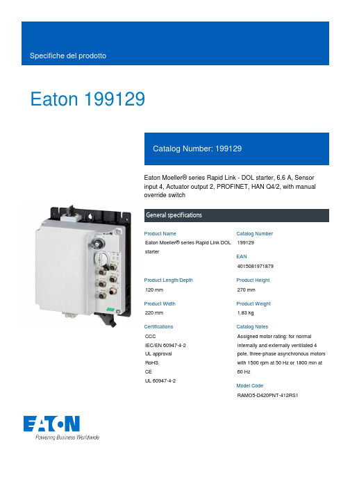
Eaton 199129Eaton Moeller® series Rapid Link - DOL starter, 6.6 A, Sensorinput 4, Actuator output 2, PROFINET, HAN Q4/2, with manualoverride switchGeneral specificationsEaton Moeller® series Rapid Link DOLstarter1991294015081971879120 mm270 mm220 mm 1.83 kgCCCIEC/EN 60947-4-2 UL approval RoHSCEUL 60947-4-2Assigned motor rating: for normal internally and externally ventilated 4 pole, three-phase asynchronous motors with 1500 rpm at 50 Hz or 1800 min at 60 HzRAMO5-D420PNT-412RS1Product Name Catalog NumberEANProduct Length/Depth Product Height Product Width Product Weight Certifications Catalog NotesModel CodeParameterization: FieldbusParameterization: KeypadParameterization: drivesConnect mobile (App) Parameterization: drivesConnectKey switch position OFF/RESETKey switch position HAND2 Actuator outputsThermistor monitoring PTCTwo sensor inputs through M12 sockets (max. 150 mA) for quick stop and interlocked manual operationElectronic motor protectionKey switch position AUTOManual override switchThermo-clickShort-circuit releaseExternal reset possibleTemperature compensated overload protection CLASS 10 AIP65NEMA 12Class A10,000,000 Operations (at AC-3)10,000,000 Operations (at AC-3)Direct starter0.3 A6.6 AIIIMotor starterPROFINET IO4000 VAC voltageCenter-point earthed star network (TN-S network) Phase-earthed AC supply systems are not permitted.DOL starterDCFeatures Fitted with:Functions ClassDegree of protectionElectromagnetic compatibility Lifespan, electricalLifespan, mechanicalModelOverload release current setting - min Overload release current setting - max Overvoltage categoryProduct categoryProtocolRated impulse withstand voltage (Uimp) System configuration typeTypeVoltage typeVertical15 g, Mechanical, According to IEC/EN 60068-2-27, 11 ms, Half-sinusoidal shock 11 ms, 1000 shocks per shaftResistance: 10 - 150 Hz, Oscillation frequencyResistance: 57 Hz, Amplitude transition frequency on accelerationResistance: 6 Hz, Amplitude 0.15 mmResistance: According to IEC/EN 60068-2-6Max. 1000 mMax. 2000 mAbove 1000 m with 1 % performance reduction per 100 m -10 °C55 °C-40 °C70 °CIn accordance with IEC/EN 50178< 95 %, no condensationAdjustable, motor, main circuit0.3 - 6.6 A, motor, main circuit6.6 A (at 150 % Overload)Maximum of one time every 60 seconds 380 - 480 V (-15 %/+10 %, at 50/60 Hz) 20 - 35 ms20 - 35 ms50/60 HzAC-53a47 Hz 3 HP10 kA0 AType 1 coordination via the power bus' feeder unit, Main circuit0 V0 V0 VMounting position Shock resistance Vibration AltitudeAmbient operating temperature - min Ambient operating temperature - max Ambient storage temperature - min Ambient storage temperature - max Climatic proofingCurrent limitationInput currentMains switch-on frequency Mains voltage tolerance Off-delayOn-delayOutput frequency Overload cycleRated frequency - min Rated frequency - max Assigned motor power at 460/480 V, 60 Hz, 3-phaseRated conditional short-circuit current (Iq)Rated conditional short-circuit current (Iq), type 2, 380 V, 400 V, 415 VShort-circuit protection (external output circuits)Rated control supply voltage (Us) at AC, 50 Hz - minRated control supply voltage (Us) at AC, 50 Hz - maxRated control supply voltage (Us) at AC, 60 Hz - min63 Hz6.6 A6.6 A0.09 kW3 kW0 kW3 kW480 V AC, 3-phase400 V AC, 3-phase50/60 Hz, fLN, Main circuitAC voltageCenter-point earthed star network (TN-S network) Phase-earthed AC supply systems are not permitted.0 V0 V0 V24 V DC (-15 %/+20 %, external via AS-Interface® plug) Connections pluggable in power section210 m, Radio interference level, maximum motor cable lengthMeets the product standard's requirements. Meets the product standard's requirements. Meets the product standard's requirements. Meets the product standard's requirements.Rapid Link 5 - brochureDA-SW-drivesConnectDA-SW-Driver DX-CBL-PC-3M0DA-SW-drivesConnect - installation helpDA-SW-USB Driver DX-COM-STICK3-KITDA-SW-drivesConnect - InstallationshilfeDA-SW-USB Driver PC Cable DX-CBL-PC-1M5Material handling applications - airports, warehouses and intra-logistics eaton-bus-adapter-rapidlink-reversing-starter-dimensions-003.epsRated operational current (Ie) at 150% overloadRated operational current (Ie) at AC-3, 380 V, 400 V, 415 V Rated operational power at 380/400 V, 50 Hz - minRated operational power at 380/400 V, 50 Hz - maxRated operational power at AC-3, 220/230 V, 50 HzRated operational power at AC-3, 380/400 V, 50 HzRated operational voltageSupply frequencySystem configuration type Rated control supply voltage (Us) at AC, 60 Hz - max Rated control supply voltage (Us) at DC - minRated control supply voltage (Us) at DC - maxRated control voltage (Uc)ConnectionNumber of auxiliary contacts (normally closed contacts) Number of auxiliary contacts (normally open contacts)Cable length10.2.2 Corrosion resistance10.2.3.1 Verification of thermal stability of enclosures10.2.3.2 Verification of resistance of insulating materials to normal heat10.2.3.3 Resist. of insul. mat. to abnormal heat/fire by internal elect. effects10.2.4 Resistance to ultra-violet (UV) radiation Brochure DisegniMeets the product standard's requirements.Does not apply, since the entire switchgear needs to be evaluated.Does not apply, since the entire switchgear needs to be evaluated.Meets the product standard's requirements.Does not apply, since the entire switchgear needs to be evaluated.Meets the product standard's requirements.Does not apply, since the entire switchgear needs to be evaluated.Does not apply, since the entire switchgear needs to be evaluated.Is the panel builder's responsibility.Is the panel builder's responsibility.Is the panel builder's responsibility.Is the panel builder's responsibility.Is the panel builder's responsibility.The panel builder is responsible for the temperature rise calculation. Eaton will provide heat dissipation data for the devices.Is the panel builder's responsibility. The specifications for the switchgear must be observed.Is the panel builder's responsibility. The specifications for the eaton-bus-adapter-rapidlink-reversing-starter-dimensions-002.eps eaton-bus-adapter-rapidlink-speed-controller-dimensions-002.eps eaton-bus-adapter-rapidlink-speed-controller-dimensions-003.epsETN.RAMO5-D420PNT-412RS1.edzIL034092ZUramo5_v13.stpramo5_v13.dwgGeneration change RAMO4 to RAMO5Generation change from RA-SP to RASP 4.0Generation Change RASP4 to RASP5Generation change from RA-MO to RAMO 4.0Generation Change RA-SP to RASP5Configuration to Rockwell PLC for Rapid LinkDA-DC-00003964.pdfDA-DC-00004184.pdfDA-DC-00004525.pdfDA-DC-00004523.pdf10.2.5 Lifting10.2.6 Mechanical impact10.2.7 Inscriptions10.3 Degree of protection of assemblies10.4 Clearances and creepage distances10.5 Protection against electric shock10.6 Incorporation of switching devices and components 10.7 Internal electrical circuits and connections10.8 Connections for external conductors10.9.2 Power-frequency electric strength10.9.3 Impulse withstand voltage10.9.4 Testing of enclosures made of insulating material 10.10 Temperature rise10.11 Short-circuit rating10.12 Electromagnetic compatibility eCAD modelIstruzioni di installazione mCAD modelNote per l'applicazione Report di certificazioneEaton Corporation plc Eaton House30 Pembroke Road Dublin 4, Ireland © 2023 Eaton. Tutti i diritti riservati. Eaton is a registered trademark.All other trademarks areproperty of their respectiveowners./socialmediaswitchgear must be observed.The device meets the requirements, provided the information in the instruction leaflet (IL) is observed.10.13 Mechanical function。
AM29DL640D50WHK资料

Publication Number 23695 Revision C Amendment 3 Issue Date December 13, 2005Am29DL640DData SheetJuly 2003The following document specifies Spansion memory products that are now offered by both Advanced Micro Devices and Fujitsu. Although the document is marked with the name of the company that originally developed the specification, these products will be offered to customers of both AMD and Fujitsu.Continuity of SpecificationsThere is no change to this datasheet as a result of offering the device as a Spansion product. Any changes that have been made are the result of normal datasheet improvement and are noted in the document revision summary, where supported. Future routine revisions will occur when appropri-ate, and changes will be noted in a revision summary.Continuity of Ordering Part NumbersAMD and Fujitsu continue to support existing part numbers beginning with "Am" and "MBM". To order these products, please use only the Ordering Part Numbers listed in this document.For More InformationPlease contact your local AMD or Fujitsu sales office for additional information about Spansion mem-ory solutions.This product has been retired and is not available for designs.For new and current designs involving TSOP packages, S29JL064H supersedes Am29DL640D and is the factory-recommended migration path. Please refer to the S29JL064H datasheet for specifications and ordering informa-tion.For new and current designs involving Fine-pitch BGA (FBGA) packages, S29PL064J supersedes Am29DL640D and is the factory-recommended migration path. Please refer to the S29PL064J Datasheet for specifications and ordering information.Availability of this document is retained for reference and historical purposes only.A D V A N C E I N F O R M A T I O NTHIS PAGE LEFT INTENTIONALL Y BLANK2December 13, 2005Publication# 23695Rev: C Amendment/3Issue Date: December 13, 2005Refer to AMD’s Website () for the latest information.Am29DL640D64 Megabit (8 M x 8-Bit/4 M x 16-Bit)CMOS 3.0 Volt-only, Simultaneous Read/Write Flash MemoryDISTINCTIVE CHARACTERISTICSARCHITECTURAL ADVANTAGESSimultaneous Read/Write operations—Data can be continuously read from one bank whileexecuting erase/program functions in another bank. —Zero latency between read and write operations Flexible Bank TM architecture—Read may occur in any of the three banks not beingwritten or erased.—Four banks may be grouped by customer to achievedesired bank divisions. Boot Sectors—T op and bottom boot sectors in the same device —Any combination of sectors can be erased Manufactured on 0.23 µm process technology Secured Silicon Sector: Extra 256 Byte sector—Factory locked and identifiable: 16 bytes available forsecure, random factory Electronic Serial Number; verifiable as factory locked through autoselectfunction. ExpressFlash option allows entire sector to be available for factory-secured data—Customer lockable: Can be read or programmed justlike other sectors. Once locked, data cannot be changed Zero Power Operation—Sophisticated power management circuits reducepower consumed during inactive periods to nearly zero.Compatible with JEDEC standards—Pinout and software compatible withsingle-power-supply flash standard PACKAGE OPTIONS 63-ball Fine Pitch BGA ■48-pin TSOPPERFORMANCE CHARACTERISTICSHigh performance—Access time as fast as 90 ns—Program time: 4 µs/word typical utilizing AcceleratefunctionUltra low power consumption (typical values)— 2 mA active read current at 1 MHz—10 mA active read current at 5 MHz—200 nA in standby or automatic sleep mode Minimum 1 million erase cycles guaranteed persector20 year data retention at 125°C—Reliable operation for the life of the system SOFTWARE FEATURESData Management Software (DMS)—AMD-supplied software manages data programming,enabling EEPROM emulation—Eases historical sector erase flash limitations Supports Common Flash Memory Interface (CFI) Program/Erase Suspend/Erase Resume—Suspends program/erase operations to allowprogramming/erasing in same bankData# Polling and Toggle Bits—Provides a software method of detecting the status ofprogram or erase cyclesUnlock Bypass Program command—Reduces overall programming time when issuingmultiple program command sequences HARDWARE FEATURESReady/Busy# output (RY/BY#)—Hardware method for detecting program or erasecycle completionHardware reset pin (RESET#)—Hardware method of resetting the internal statemachine to the read modeWP#/ACC input pin—Write protect (WP#) function protects sectors 0, 1,140, and 141, regardless of sector protect status —Acceleration (ACC) function accelerates programtimingSector protection—Hardware method of locking a sector, eitherin-system or using programming equipment, to prevent any program or erase operation within that sector—Temporary Sector Unprotect allows changing data inprotected sectors in-systemThis product has been retired and is not available for designs.For new and current designs involving TSOP packages, S29JL064H supersedes Am29DL640D and is the factory-recommended migration path. Please refer to the S29JL064H datasheet for specifications and ordering information.For new and current designs involving Fine-pitch BGA (FBGA) packages, S29PL064J supersedes Am29DL640D and is the factory-recommended migration path. Please refer to the S29PL064J Datasheet for specifications and ordering information.Availability of this document is retained for reference and historical purposes only.GENERAL DESCRIPTIONThe Am29DL640D is a 64megabit, 3.0 volt-only flash memory device, organized as 4,194,304 words of 16 bits each or 8,388,608 bytes of 8 bits each. Word mode data appears on DQ0–DQ15; byte mode data appears on DQ0–DQ7. The device is designed to be programmed in-system with the standard 3.0 volt V CC supply, and can also be programmed in standard EPROM programmers.The device is available with an access time of 90 or 120 ns and is offered in 48-pin TSOP and 63-ball Fine-Pitch BGA. Standard control pins—chip enable (CE#), write enable (WE#), and output enable (OE#)—control normal read and write operations, and avoid bus contention issues.The device requires only a single 3.0 volt power sup-ply for both read and write functions. Internally generated and regulated voltages are provided for the program and erase operations.Simultaneous Read/Write Operations with Zero LatencyThe Simultaneous Read/Write architecture provides simultaneous operation by dividing the memory space into four banks, two 8 Mb banks with small and large sectors, and two 24 Mb banks of large sectors. Sector addresses are fixed, system software can be used to form user-defined bank groups.During an Erase/Program operation, any of the three non-busy banks may be read from. Note that only two banks can operate simultaneously. The device can im-prove overall system performance by allowing a host system to program or erase in one bank, then immediately and simultaneously read from the other bank, with zero latency. This releases the system from waiting for the completion of program or erase operations.The Am29DL640D can be organized as both a top and bottom boot sector configuration.Am29DL640D FeaturesThe Secured Silicon Sector is an extra 256 byte sec-tor capable of being permanently locked by AMD or customers. The Secured Silicon Indicator Bit (DQ7) is permanently set to a 1 if the part is factory locked, and set to a 0 if customer lockable. This way, cus-tomer lockable parts can never be used to replace a factory locked part.Factory locked parts provide several options. The Se-cured Silicon Sector may store a secure, random 16byte ESN (Electronic Serial Number), customer code (programmed through AMD’s ExpressFlash service), or both. Customer Lockable parts may utilize the Se-cured Silicon Sector as bonus space, reading and writing like any other flash sector, or may permanently lock their own code there.DMS (Data Management Software) allows systems to easily take advantage of the advanced architecture of the simultaneous read/write product line by allowing removal of EEPROM devices. DMS also allows the system software to be simplified, as it performs all functions necessary to modify data in file structures, as opposed to single-byte modifications. To write or update a particular piece of data (a phone number or configuration data, for example), the user only needs to state which piece of data is to be updated, and where the updated data is located in the system. This is an advantage compared to systems where user-written software must keep track of the old data location, status, logical to physical translation of the data onto the Flash memory device (or memory de-vices), and more. Using DMS, user-written software does not need to interface with the Flash memory di-rectly. Instead, the user's software accesses the Flash memory by calling one of only six functions. AMD pro-vides this software to simplify system design and software integration efforts.The device offers complete compatibility with the JEDEC single-power-supply Flash command set standard. Commands are written to the command register using standard microprocessor write timings. Reading data out of the device is similar to reading from other Flash or EPROM devices.The host system can detect whether a program or erase operation is complete by using the device sta-tus bits: RY/BY# pin, DQ7 (Data# Polling) and DQ6/DQ2 (toggle bits). After a program or erase cycle has been completed, the device automatically returns to the read mode.The sector erase architecture allows memory sec-tors to be erased and reprogrammed without affecting the data contents of other sectors. The device is fully erased when shipped from the factory.Hardware data protection measures include a low V CC detector that automatically inhibits write opera-tions during power transitions. The hardware sector protection feature disables both program and erase operations in any combination of the sectors of mem-o r y.T h i s c a n b e a c h i eve d i n-s y s t e m o r v i a programming equipment.The device offers two power-saving features. When addresses have been stable for a specified amount of time, the device enters the automatic sleep mode. The system can also place the device into the standby mode. Power consumption is greatly re-duced in both modes.Bank Megabits Sector SizesBank 18 MbEight 8 Kbyte/4 Kword, Fifteen 64 Kbyte/32 KwordBank 224 Mb Forty-eight 64 Kbyte/32 Kword Bank 324 Mb Forty-eight 64 Kbyte/32 KwordBank 48 MbEight 8 Kbyte/4 Kword, Fifteen 64 Kbyte/32 Kword2Am29DL640D December 13, 2005TABLE OF CONTENTSProduct Selector Guide . . . . . . . . . . . . . . . . . . . . .5 Block Diagram . . . . . . . . . . . . . . . . . . . . . . . . . . . . 5 Connection Diagrams . . . . . . . . . . . . . . . . . . . . . . .6 Pin Description . . . . . . . . . . . . . . . . . . . . . . . . . . . .7 Ordering Information . . . . . . . . . . . . . . . . . . . . . . .8 Device Bus Operations . . . . . . . . . . . . . . . . . . . . . .9 Table 1. Am29DL640D Device Bus Operations (9)Word/Byte Configuration (9)Requirements for Reading Array Data (9)Writing Commands/Command Sequences (10)Accelerated Program Operation (10)Autoselect Functions (10)Simultaneous Read/Write Operations with Zero Latency (10)Standby Mode (10)Automatic Sleep Mode (11)RESET#: Hardware Reset Pin (11)Output Disable Mode (11)Table 2. Am29DL640D Sector Architecture (11)Table 3. Bank Address (14)Secured Silicon Sector Addresses (14)Autoselect Mode (14)Table 5. Am29DL640D Autoselect Codes, (High Voltage Method) 15 Sector/Sector Block Protection and Unprotection 16 Table 6. Am29DL640D Boot Sector/Sector Block Addresses for Pro-tection/Unprotection (16)Write Protect (WP#) (17)Table 7. WP#/ACC Modes (17)Temporary Sector Unprotect (17)Figure 1. Temporary Sector Unprotect Operation (17)Figure 2. In-System Sector Protect/Unprotect Algorithms (18)Secured Silicon SectorFlash Memory Region (19)Figure 3. Secured Silicon Sector Protect Verify (20)Hardware Data Protection (20)Low VCC Write Inhibit (20)Write Pulse “Glitch” Protection (20)Logical Inhibit (20)Power-Up Write Inhibit (20)Common Flash Memory Interface (CFI) . . . . . . .20 Table 8. CFI Query Identification String (21)System Interface String (21)Table 10. Device Geometry Definition (22)Table 11. Primary Vendor-Specific Extended Query.. 23 Command Definitions . . . . . . . . . . . . . . . . . . . . . .24 Reading Array Data (24)Reset Command (24)Autoselect Command Sequence (24)Enter/Exit Secured Silicon SectorCommand Sequence (24)Byte/Word Program Command Sequence (25)Unlock Bypass Command Sequence (25)Figure 4. Program Operation (26)Chip Erase Command Sequence (26)Sector Erase Command Sequence (26)Erase Suspend/Erase Resume Commands (27)Figure 5. Erase Operation (27)Table 12. Am29DL640D Command Definitions.......... 28Write Operation Status . . . . . . . . . . . . . . . . . . . . 29 DQ7: Data# Polling .. (29)Figure 6. Data# Polling Algorithm (29)RY/BY#: Ready/Busy# (30)DQ6: Toggle Bit I (30)Figure 7. Toggle Bit Algorithm (30)DQ2: Toggle Bit II (31)Reading Toggle Bits DQ6/DQ2 (31)DQ5: Exceeded Timing Limits (31)DQ3: Sector Erase Timer (31)Table 13. Write Operation Status (32)Absolute Maximum Ratings . . . . . . . . . . . . . . . . 33 Figure 8. Maximum Negative Overshoot Waveform (33)Figure 9. Maximum Positive Overshoot Waveform (33)Operating Ranges . . . . . . . . . . . . . . . . . . . . . . . . 33 DC Characteristics . . . . . . . . . . . . . . . . . . . . . . . . 34 Figure 10. I CC1 Current vs. Time (Showing Active andAutomatic Sleep Currents) (35)Figure 11. Typical I CC1 vs. Frequency (35)Test Conditions . . . . . . . . . . . . . . . . . . . . . . . . . . 36 Figure 12. Test Setup (36)KEY TO SWITCHING WAVEFORMS . . . . . . . . . . 36 Figure 13. Input Waveforms and Measurement Levels (36)AC Characteristics . . . . . . . . . . . . . . . . . . . . . . . . 37 Read-Only Operations (37)Figure 14. Read Operation Timings (37)Hardware Reset (RESET#) (38)Figure 15. Reset Timings (38)Word/Byte Configuration (BYTE#) (39)Figure 16. BYTE# Timings for Read Operations (39)Figure 17. BYTE# Timings for Write Operations (39)Erase and Program Operations (40)Figure 18. Program Operation Timings (41)Figure 19. Accelerated Program Timing Diagram (41)Figure 20. Chip/Sector Erase Operation Timings (42)Figure 21. Back-to-back Read/Write Cycle Timings (43)Figure 22. Data# Polling Timings (During Embedded Algorithms). 43 Figure 23. Toggle Bit Timings (During Embedded Algorithms) (44)Figure 24. DQ2 vs. DQ6 (44)Temporary Sector Unprotect (45)Figure 25. Temporary Sector Unprotect Timing Diagram (45)Figure 26. Sector/Sector Block Protect andUnprotect Timing Diagram (46)Alternate CE# Controlled Erase and Program Operations (47)Figure 27. Alternate CE# Controlled Write (Erase/Program)Operation Timings (48)Erase And Programming Performance . . . . . . . 49 Latchup Characteristics. . . . . . . . . . . . . . . . . . . . 49 TSOP Pin Capacitance. . . . . . . . . . . . . . . . . . . . . 49 Data Retention. . . . . . . . . . . . . . . . . . . . . . . . . . . . 49 Physical Dimensions . . . . . . . . . . . . . . . . . . . . . . 50 FBE063—63-Ball Fine-Pitch Ball Grid Array (FBGA)12x11mm package (50)TS 048—48-Pin Standard TSOP (51)Revision Summary . . . . . . . . . . . . . . . . . . . . . . . . 52December 13, 2005Am29DL640D3PRODUCT SELECTOR GUIDEPart Number Am29DL640DSpeed Option Standard Voltage Range: V CC = 2.7–3.6 V90120Max Access Time (ns), t ACC90120CE# Access (ns), t CE90120OE# Access (ns), t OE3550 BLOCK DIAGRAM4Am29DL640D December 13, 2005CONNECTION DIAGRAMSDecember 13, 2005Am29DL640D5PIN DESCRIPTIONA0–A21=22 AddressesDQ0–DQ14=15 Data Inputs/Outputs(x16-only devices)DQ15/A-1=DQ15 (Data Input/Output, wordmode), A-1 (LSB Address Input, bytemode)CE#=Chip EnableOE#=Output EnableWE#=Write EnableWP#/ACC=Hardware Write Protect/Acceleration PinRESET#=Hardware Reset Pin, Active Low BYTE#=Selects 8-bit or 16-bit modeRY/BY#=Ready/Busy OutputV CC= 3.0 volt-only single power supply(see Product Selector Guide for speedoptions and voltage supply tolerances) V SS=Device GroundNC=Pin Not Connected Internally LOGIC SYMBOL2216 or 8DQ0–DQ15(A-1)A0–A21CE#OE#WE#RESET#BYTE#RY/BY#WP#/ACC6Am29DL640D December 13, 2005ORDERING INFORMATIONStandard ProductsAMD standard products are available in several packages and operating ranges. The order number (Valid Combination) is formed by a combination of the following:Valid CombinationsValid Combinations list configurations planned to be supported in volume for this device. Consult the local AMD sales office to con-firm availability of specific valid combinations and to check on newly released combinations.Am29DL640D90 E IOPTIONAL PROCESSINGBlank=Standard ProcessingN=16-byte ESN devices(Contact an AMD representative for more information)TEMPERATURE RANGEI = Industrial (–40°C to +85°C)E =Extended (–55°C to +125°C)F=Industrial for Pb-free Package (–40°C to +85°C)K=Extended for Pb-free Package (–55°C to +125°C)PACKAGE TYPEE=48-Pin Thin Small Outline Package(TSOP) Standard Pinout (TS 048)WH=63-Ball Fine-Pitch Ball Grid Array,0.80 mm pitch, 12 x 11 mm package (FBE063)SPEED OPTIONSee Product Selector Guide and Valid CombinationsDEVICE NUMBER/DESCRIPTIONAm29DL640D64 Megabit (8 M x 8-Bit/4 M x 16-Bit) CMOS Flash Memory3.0 Volt-only Read, Program, and EraseValid Combinations for TSOP PackagesAm29DL640D90EI, EFAm29DL640D120EI, EE, EF, EK Valid Combinations for BGA PackagesOrder Number Package MarkingAm29DL640D90WHF,WHID640D90V I, FAm29DL640D120WHI,WHE,WHF,WHKD640D12VI, E,F, KDecember 13, 2005Am29DL640D7DEVICE BUS OPERATIONSThis section describes the requirements and use of the device bus operations, which are initiated through the internal command register. The command register itself does not occupy any addressable memory loca-tion. The register is a latch used to store the commands, along with the address and data informa-tion needed to execute the command. The contents of the register serve as inputs to the internal state ma-chine. The state machine outputs dictate the function of the device. Table1 lists the device bus operations, the inputs and control levels they require, and the re-sulting output. The following subsections describe each of these operations in further detail.Table 1.Am29DL640D Device Bus OperationsLegend: L = Logic Low = V IL, H = Logic High = V IH, V ID = 8.5–12.5V, V HH = 9.0 ± 0.5 V, X = Don’t Care, SA = Sector Address, A IN = Address In, D IN = Data In, D OUT = Data OutNotes:1.Addresses are A21:A0 in word mode (BYTE# = V IH), A21:A-1 in byte mode (BYTE# = V IL).2.The sector protect and sector unprotect functions may also be implemented via programming equipment. See the Sector/SectorBlock Protection and Unprotection section.3.If WP#/ACC = V IL, sectors 0, 1, 140, and 141 remain protected. If WP#/ACC = V IH, protection on sectors 0, 1, 140, and 141depends on whether they were last protected or unprotected using the method described in Sector/Sector Block Protection and Unprotection. If WP#/ACC = V HH, all sectors are unprotected.Word/Byte ConfigurationThe BYTE# pin controls whether the device data I/O pins operate in the byte or word configuration. If the BYTE# pin is set at logic “1,” the device is in word con-figuration, DQ0–DQ15 are active and controlled by CE# and OE#.If the BYTE# pin is set at logic “0,” the device is in byte configuration, and only data I/O pins DQ0–DQ7 are active and controlled by CE# and OE#. The data I/O pins DQ8–DQ14 are tri-stated, and the DQ15 pin is used as an input for the LSB (A-1) address function.Requirements for Reading Array DataTo read array data from the outputs, the system must drive the CE# and OE# pins to V IL. CE# is the power control and selects the device. OE# is the output con-trol and gates array data to the output pins. WE# should remain at V IH. The BYTE# pin determines whether the device outputs array data in words or bytes.The internal state machine is set for reading array data upon device power-up, or after a hardware reset. This ensures that no spurious alteration of the memory content occurs during the power transition. No com-mand is necessary in this mode to obtain array data. Standard microprocessor read cycles that assert validOperation CE#OE#WE#RESET#WP#/ACC Addresses(Note 2)DQ0–DQ7DQ8–DQ15BYTE#= V IHBYTE#= V ILRead L L H H L/H A IN D OUT D OUT DQ8–DQ14 =High-Z, DQ15 = A-1 Write L H L H(Note 3)A IN D IN D INStandby V CC±0.3 VX XV CC±0.3 VH X High-Z High-Z High-ZOutput Disable L H H H L/H X High-Z High-Z High-Z Reset X X X L L/H X High-Z High-Z High-ZSector Protect (Note 2)L H L V ID L/HSA, A6 = L,A1 = H, A0 = LD IN X XSector Unprotect (Note 2)L H L V ID(Note 3)SA, A6 = H,A1 = H, A0 = LD IN X XTemporary SectorUnprotectX X X V ID(Note 3)A IN D IN D IN High-Z8Am29DL640D December 13, 2005addresses on the device address inputs produce valid data on the device data outputs. Each bank remains enabled for read access until the command register contents are altered.Refer to the AC Read-Only Operations table for timing specifications and to Figure14 for the timing diagram.I CC1 in the DC Characteristics table represents the ac-tive current specification for reading array data. Writing Commands/Command Sequences T o write a command or command sequence (which in-cludes programming data to the device and erasing sectors of memory), the system must drive WE# and CE# to V IL, and OE# to V IH.For program operations, the BYTE# pin determines whether the device accepts program data in bytes or words. Refer to Word/Byte Configuration for more information.The device features an Unlock Bypass mode to facili-tate faster programming. Once a bank enters the Unlock Bypass mode, only two write cycles are re-quired to program a word or byte, instead of four. The Byte/Word Program Command Sequence section has details on programming data to the device using both standard and Unlock Bypass command sequences. An erase operation can erase one sector, multiple sec-tors, or the entire device. T able2 indicates the address space that each sector occupies. The device address space is divided into four banks: Banks 1 and 4 con-tains the boot/parameter sectors, and Banks 2 and 3 contains the larger, code sectors of uniform size. A “bank address” is the address bits required to uniquely select a bank. Similarly, a “sector address” is the ad-dress bits required to uniquely select a sector. The Command Definitions section has details on erasing a sector or the entire chip, or suspending/resuming the erase operation.I CC2 in the DC Characteristics table represents the ac-tive current specification for the write mode. The AC Characteristics section contains timing specification tables and timing diagrams for write operations. Accelerated Program OperationThe device offers accelerated program operations through the ACC function. This is one of two functions provided by the WP#/ACC pin. This function is prima-rily intended to allow faster manufacturing throughput at the factory.If the system asserts V HH on this pin, the device auto-matically enters the aforementioned Unlock Bypass mode, temporarily unprotects any protected sectors, and uses the higher voltage on the pin to reduce the time required for program operations. The system would use a two-cycle program command sequence as required by the Unlock Bypass mode. Removing V HH from the WP#/ACC pin returns the device to nor-mal operation. Note that V HH must not be asserted on WP#/ACC for operations other than accelerated pro-gramming, or device damage may result. In addition, the WP#/ACC pin must not be left floating or uncon-nected; inconsistent behavior of the device may result. See “Write Protect (WP#)” on page16 for related information.Autoselect FunctionsIf the system writes the autoselect command se-quence, the device enters the autoselect mode. The system can then read autoselect codes from the inter-nal register (which is separate from the memory array) on DQ15–DQ0. Standard read cycle timings apply in this mode. Refer to the Autoselect Mode and Autose-l e c t C o m m a n d S e q u e n c e s e c t i o n s fo r m o r e information.Simultaneous Read/Write Operations with Zero LatencyThis device is capable of reading data from one bank of memory while programming or erasing in the other bank of memory. An erase operation may also be sus-pended to read from or program to another location within the same bank (except the sector being erased). Figure21 shows how read and write cycles may be initiated for simultaneous operation with zero latency. ICC6 and ICC7 in the DC Characteristics table represent the current specifications for read-while-pro-gram and read-while-erase, respectively.Standby ModeWhen the system is not reading or writing to the de-vice, it can place the device in the standby mode. In this mode, current consumption is greatly reduced, and the outputs are placed in the high impedance state, independent of the OE# input.The device enters the CMOS standby mode when the CE# and RESET# pins are both held at V CC ± 0.3 V. (Note that this is a more restricted voltage range than V IH.) If CE# and RESET# are held at V IH, but not within V CC ± 0.3 V, the device is in the standby mode, but the standby current is greater. The device requires stan-dard access time (t CE) for read access when the device is in either of these standby modes, before it is ready to read data.If the device is deselected during erasure or program-ming, the device draws active current until the operation is completed.ICC3 in the DC Characteristics table represents the standby current specification.Automatic Sleep ModeThe automatic sleep mode minimizes Flash device en-ergy consumption. The device automatically enables this mode when addresses remain stable for t ACC + 30ns. The automatic sleep mode is independent of the CE#, WE#, and OE# control signals. Standard ad-dress access timings provide new data when addresses are changed. While in sleep mode, output data is latched and always available to the system. ICC5 in the DC Characteristics table represents the automatic sleep mode current specification. RESET#: Hardware Reset PinThe RESET# pin provides a hardware method of re-setting the device to reading array data. When the RESET# pin is driven low for at least a period of t RP, the device immediately terminates any operation in progress, tristates all output pins, and ignores all read/write commands for the duration of the RESET# pulse. The device also resets the internal state ma-chine to reading array data. The operation that was interrupted should be reinitiated once the device is ready to accept another command sequence, to en-sure data integrity.Current is reduced for the duration of the RESET# pulse. When RESET# is held at V SS±0.3 V, the device draws CMOS standby current (ICC4). If RESET# is held at V IL but not within V SS±0.3 V, the standby cur-rent is greater.The RESET# pin may be tied to the system reset cir-cuitry. A system reset would thus also reset the Flash memory, enabling the system to read the boot-up firm-ware from the Flash memory.If RESET# is asserted during a program or erase op-eration, the RY/BY# pin remains a “0” (busy) until the internal reset operation is complete, which requires a time of t READY (during Embedded Algorithms). The sys-tem can thus monitor RY/BY# to determine whether the reset operation is complete. If RESET# is asserted when a program or erase operation is not executing (RY/BY# pin is “1”), the reset operation is completed within a time of t READY (not during Embedded Algo-rithms). The system can read data t RH after the RESET# pin returns to V IH.Refer to the AC Characteristics tables for RESET# pa-rameters and to Figure15 for the timing diagram. Output Disable ModeWhen the OE# input is at V IH, output from the device is disabled. The output pins are placed in the high impedance state.Table 2.Am29DL640D Sector ArchitectureBank Sector Sector AddressA21–A12Sector Size(Kbytes/Kwords)(x8)Address Range(x16)Address RangeBank 1SA000000000008/4000000h–001FFFh00000h–00FFFh SA100000000018/4002000h–003FFFh01000h–01FFFh SA200000000108/4004000h–005FFFh02000h–02FFFh SA300000000118/4006000h–007FFFh03000h–03FFFh SA400000001008/4008000h–009FFFh04000h–04FFFh SA500000001018/400A000h–00BFFFh05000h–05FFFh SA600000001108/400C000h–00DFFFh06000h–06FFFh SA700000001118/400E000h–00FFFFFh07000h–07FFFh SA80000001xxx64/32010000h–01FFFFh08000h–0FFFFh SA90000010xxx64/32020000h–02FFFFh10000h–17FFFh SA100000011xxx64/32030000h–03FFFFh18000h–1FFFFh SA110000100xxx64/32040000h–04FFFFh20000h–27FFFh SA120000101xxx64/32050000h–05FFFFh28000h–2FFFFh SA130000110xxx64/32060000h–06FFFFh30000h–37FFFh SA140000111xxx64/32070000h–07FFFFh38000h–3FFFFh SA150001000xxx64/32080000h–08FFFFh40000h–47FFFh SA160001001xxx64/32090000h–09FFFFh48000h–4FFFFh SA170001010xxx64/320A0000h–0AFFFFh50000h–57FFFh SA180001011xxx64/320B0000h–0BFFFFh58000h–5FFFFh SA190001100xxx64/320C0000h–0CFFFFh60000h–67FFFh SA200001101xxx64/320D0000h–0DFFFFh68000h–6FFFFh SA210001110xxx64/320E0000h–0EFFFFh70000h–77FFFh SA220001111xxx64/320F0000h–0FFFFFh78000h–7FFFFh。
- 1、下载文档前请自行甄别文档内容的完整性,平台不提供额外的编辑、内容补充、找答案等附加服务。
- 2、"仅部分预览"的文档,不可在线预览部分如存在完整性等问题,可反馈申请退款(可完整预览的文档不适用该条件!)。
- 3、如文档侵犯您的权益,请联系客服反馈,我们会尽快为您处理(人工客服工作时间:9:00-18:30)。
专业品质,
静触点
超 小 型 -D连 接 器
FOR庇护室内 /室外环境应用
D-Sub
尺寸20 触点,固定
专业品质 连接器
MD / ED系列IEC出版物807-2
性能等级二
U.L.认 可 文件# E49351
CSA认 可 文件# LR54219
电信
U.L.文件# 14098
3
32
36
L
0.150 [3.81]
0.375 [9.53]
0.236 [5.99]
对于直印刷电路板安装
触点 ,在指定码数 订购信息步骤 4.
ØD
0.028 [0.71]
0.028 [0.71]
0.024 [0.61]
铆装隔板与 推入式紧固件 磷青铜
0.010 [0.25]
MIN.
L
固定母头螺旋顶
ØD
2.272 [57.71]
2.272 [57.71]
2.178 [55.32]
2.178 [55.32]
H ±0.010 [0.25]
0.422 [10.72]
0.422 [10.72]
0.422 [10.72]
0.422 [10.72]
0.422 [10.72]
0.422 [10.72]
0.539 [13.69]
电气特性:
触点额定电流: 初稿接触 抵抗性: 绝缘电阻: 耐电压: 间隙和爬电
距离 [最小 ]:
工作电压:
气候特征:
温度范围: 恒定湿热 国家:
7.5安培名义.
欧姆最大0.008. 5G欧姆. 1000 V均方根
0.039英寸[1.0毫米. 300 V均方根
-55°C至+ 125°C.
10天.
壳: 极化方式: 安装要尖括号:
1.541 [39.14]
2.088 [53.04]
2.088 [53.04]
1.770 [44.96]
1.770 [44.96]
2.729 [69.32]
2.729 [69.32]
2.635 [66.93]
2.635 [66.93]
B ±0.005 [0.13]
0.643 [16.33]
0.971 [24.66]
系列连接器是可配对,并与所有D类微型连接器符合IEC 807-2和 MIL-DTL-24308兼容.
印刷电路板各式各样安装硬件,电缆支架 抽油烟机和锁定系统,有现货供应.
梅洛-D和欧洲-D系列连接器符合EIA RS-232和RS 449,和CCITT X.24接口连接器需求.
RoHS触点技术 销售细节 . 标准
梅洛-D和欧洲-D系列连接器专业品质连接 建议在具有正常通风遮蔽,不腐蚀室内或室外环境中使用器,但没有 温度或湿度控制.这些固定触点连接器符合IEC 807-2,性能级别二尺 寸和性能要求.
梅洛-D和欧洲-D系列连接器采用精密加工触点 被固定在连接器主体内.母头性接触是一个开放式设计接触,精密加工 高强度磷青铜.
ED
6 0.375 [9.53] 0.360 [9.14]
DD
32 0.515 [13.08] 0.165 [4.19]
ODD
32 0.375 [9.53] 0.165 [4.19]
ODD
5
------
------
HDC
32 0.375 [9.53] 0.240 [6.10]
HDC
36 0.375 [9.53] 0.101 [2.57]
MD / ED系列
0.135 [3.43] 0.352 [8.94]
对于焊杯触点 ,指定 在步骤 4代码 2
订购信息.
典型型号: ED15M200T2Z
修正公头性和母头性提供偏光螺旋千斤顶. 指定订购信息步骤 7码 T6.
典型型号: MD15M200T6Z
直印刷电路板安装连接器
CODE NUMBER
1.511 [38.38]
1.251 [31.78]
2.159 [54.84]
2.064 [52.43]
B1 ±0.005 [0.13] 0.666 [16.92]
0.994 [25.25]
1.534 [38.96]
1.274 [32.36]
2.182 [55.42]
2.079 [52.81]
C ±0.005 [0.13]
0.217 [5.51]
0.237 [6.02]
0.230 [5.84]
0.243 [6.17]
0.230 [5.84]
0.243 [6.17]
M ±0.010 [0.25]
0.422 [10.72]
0.429 [10.90]
0.422 [10.72]
0.429 [10.90]
0.426 [10.82]
D ±0.005 [0.13]
0.311 [7.90]
0.311 [7.90]
0.311 [7.90]
0.431 [10.95]
0.311 [7.90]
0.423 [10.74]
D1 ±0.005 [0.13] 0.329 [8.36]
0.329 [8.36]
0.329 [8.36]
0.450 [11.43]
0.494 [12.55]
0.605 [15.37]
0.605 [15.37]
G ±0.010 [0.25]
0.759 [19.28]
0.759 [19.28]
1.083 [27.51]
1.083 [27.51]
1.625 [41.28]
1.625 [41.28]
1.322 [33.58]
1.322 [33.58]
HDC
6 0.375 [9.53] 0.360 [9.14]
指定订购信息步骤 6代码 F或 Q. F代表铁 素体电感和 Q为铁素体电感与推入式紧固件 .
L 90°印 刷 电 路 板 安 装 连 接 器
铁素体电感酒吧
Aห้องสมุดไป่ตู้
0.135±0.005 [3.43±0.13]
Fixed female jackscrews
0.539 [13.69]
0.422 [10.72]
0.422 [10.72]
0.534 [13.56]
0.534 [13.56]
K ±0.005 [0.13]
0.233 [5.92]
0.243 [6.17]
0.233 [5.92]
0.243 [6.17]
0.230 [5.84]
0.243 [6.17]
可选壳件
与环球 FLOAT支架 [F]
0.120±0.010 [3.05±0.25]
MD / ED系列
Ø0.120±0.005 [Ø3.05±0.13]
安装孔,两个地方 不锈钢外壳(0选项) Ø0.154[3.91]安装孔, 两地(02选项)
0.032 [0.81]
总径向浮动量
[ ] Ø0.086+0.005 Ø2.18+0.13
典型型号: MD25F3S60T0
0.225 [5.71]
滤波特性
铁素体电感酒吧EMI / RFI噪声抑制
铆装焊盘片与推进式 紧固件磷青铜
直印刷电路板安装连接器
固定母头螺旋顶
IMPEDANCE ATTENUATION [dB]
ATTENUATION*
FREQUENCY *NO-LOAD CONDITION
钢与锡板;锌板用重铬酸盐密封.其他材料和 可根据要求完成.
尼龙塑料,铜或锡板;锌板用重铬酸盐密封 . 磷青铜或铍铜与锡板.
钢锌板和重铬酸盐密封,或清除锌板.
滑动锁,锁片,钢,镍板.
热塑性UL 94V-0.复合材料,铜或 钢锌板和重铬酸盐密封.
机械特性:
固定触点:
在绝缘体: 耐焊 铁热:
梅洛 -D
欧元 -D
材料:镍锌陶瓷.
0.010 [0.25]最小
SERIES CODE NO.
A
L
MD
32
MD
4
IMPEDANCMED [OHMS]59
0.375 [9.53] 0.240 [6.10]
------
------
------
------
MD
6 0.375 [9.53] 0.360 [9.14]
ED
36 0.375 [9.53] 0.101 [2.57]
0.329 [8.36]
0.441 [11.20]
E ±0.015 [0.38]
0.494 [12.55]
0.494 [12.55]
0.494 [12.55]
0.494 [12.55]
0.494 [12.55]
0.494 [12.55]
0.605 [15.37]
0.605 [15.37]
0.494 [12.55]
螺旋千斤顶和铆接紧固件用0.120英寸[ 3.05毫米]通孔,和螺纹铆接紧固件440螺纹和尼龙锁紧刀片.
快速安装推入式紧固件和螺纹位置.
螺旋千斤顶和振动锁定系统. 根据IEC 512-5 500次以上.
芯片中文手册,看全文,戳
D-Sub
专业品质,
静触点
超 小 型 -D连 接 器
FOR庇护室内 /室外环境应用
六标准连接器变体安排,9,15个提供, 25,29,37和50 触点.每个梅洛-D连接器变种可用 接触终端进行焊杯,包装后,直和90°
印刷电路板安装端子具有三个印刷电路板一个选择
脚印.每欧元-D接口变体可与端子接触 印刷电路板国家为焊杯,包装后直和90°安装 按欧洲标准公制脚印终端.梅洛-D和欧洲-D