All-solid photonic bandgap fiber-ol-29-20-2369
Mellanox MMA2P00-AS MMA2P00-ASHT 25GbE SFP28 光纤传输器

Mellanox® MMA2P00-AS/MMA2P00-ASHT is a pluggable SFP28 optical transceiver designed foruse in 25GbE Ethernet. It incorporates Mellanox integrated circuit technology in order to provide highperformance at low power. The transceiver operates over a pair of multi-mode fibers (MMF), using anominal wavelength of 850nm, and is SFF-8402 compliant.MMA2P00-AS/MMA2P00-ASHT has a standard SFP28 connector on the electrical side towards the hostsystem supporting IEEE 802.3bm. The optical interface is composed of two optical channels/fibers, onein each direction, intended for a multi-mode optical cable connected via standard LC connectors. Eachchannel/fiber operates at signaling rates up to 25.78125GBd.The transceiver offers selectable retiming for both its optical transmitter and receiver for the 25Gb/s rate,and it also supports lower bit rates without. The transmitter has programmable input equalizers and inputsquelch function, while the receiver has programmable output amplitude and pre-emphasis.Rigorous production testing ensures the best out-of-the-box installation experience, performance, anddurability.T able 1 - Absolute Maximum RatingsT able 2 - Operational Module InformationNotes: 1. Internal temperature readout through DDMI of up to 75°C is allowed. 2. Internal temperature readout through DDMI of up to 90°C is allowed.MMA2P00-AS | MMA2P00-ASHT25GbE SR SFP28 MMF Optical Transceiver†PRODUCT BRIEFINTERCONNECT©2019 Mellanox Technologies. All rights reserved.†For illustration only. Actual products may vary.350 Oakmead Parkway, Suite 100, Sunnyvale, CA 94085Tel: 408-970-3400 • Fax: © Copyright 2019. Mellanox Technologies. All rights reserved.Mellanox and Mellanox logo are registered trademarks of Mellanox Technologies, Ltd.LinkX is a trademark of Mellanox Technologies, Ltd. All other trademarks are property of their respective owners.Mellanox 25GbE SR SFP28 MMF T ransceiverpage 2Warranty InformationMellanox LinkX optical transceivers include a 1-year limited hardware warranty, which covers parts repair or replacement.Mechanical Schematics53911PB Rev 1.22Table 3 - Part Number and Description。
中央凹陷优化大模场面积光纤的计算与设计
中央凹陷优化大模场面积光纤的计算与设计邬家成;李国强【摘要】为了设计性能更好的高功率光纤激光器,提出并在数值上优化了一个20/400μm的中央折射率凹陷的阶跃型光纤.中央折射率凹陷深度为0.0005,直径为5μm,使1064nm光纤的基本模式有效面积增加了12%.结果表明,有中央折射率凹陷的20/400μm 阶跃型光纤适用于高功率光纤激光器.%To develop better high power fiber laser,we proposed and numerically optimized a20/400μm step-index fiber with central index dip.Central index dip with depth of 0.0005 and diameter of 5μm makes the fundamental mode Aeff increase by 12%at 1064nm.The results indicate 20/400μm SIF fiber with central index dip(CID)is suitable for high power fiber laser.【期刊名称】《佳木斯大学学报(自然科学版)》【年(卷),期】2018(036)003【总页数】2页(P479-480)【关键词】中央凹陷;阶跃型;光纤激光器;大模场光纤【作者】邬家成;李国强【作者单位】安徽中医药大学数理教研室,安徽合肥 230012;安徽中医药大学数理教研室,安徽合肥 230012【正文语种】中文【中图分类】TN2490 引言非线性效应,如受激拉曼散射,受激布里渊散射总是被认为是传统阶跃型掺镱光纤激光器功率提升[1~6]的限制因素之一。
考虑到非线性效应与光纤的模场面积成反比,因此设计良好的大模场光纤是高功率光纤激光器的发展所急需的。
为了抑制非线性效应,一些新的光纤设计最近被提出以扩大基模有效模场面积[1~5]。
CommScope FiberGuide 光纤管理系统产品说明书

DATA SHEETFiberGuide ® systemHorizontal and vertical straight sections Downspouts Cut-in T transitional sectionExpandable straight sectionJunctionsSupport hardware Flex vertical kitsHorizontal and vertical elbowsCommScope’s FiberGuide ® fiber cable management system is a trough system designed to protect and route fiber-optic patch cords, multi-fiber cable assemblies, and intra-facility fiber cable (IFC) to and from fiber splice enclosures, fiber distribution frames, and fiber-optic terminal devices. The FiberGuide system is designed to ensure that a 2-inch (5-cm) minimum bend radius is maintained throughout the system. This document provides an overview of the strengths of the FiberGuide system, and key questions to ask when comparing FiberGuide to other fiber cable management systems.The FiberGuide system is available in a variety of sizes:•2x2— Ideal for smaller installations or vertical routing of a maximum of 821 2-mm patch cords. All 2x2 FiberGuide products are shipped with cover.•2x6—Designed for height-restricted environments with a maximum capacity of 2,687 2-mm patch cords. •4x4—Maximum trough capacity to support 3,509 2-mm patch cords, 4.8 lbs/ft. •4x6—Maximum trough capacity to support 5,151 2-mm patch cords, 7.1 lbs/ft. •4x12—Maximum trough capacity to support 10,080 2-mm patch cords, 14.2 lbs/ft.•4x24 —Maximum trough capacity to support 19,937 2-mm patch cords.Basic components include:The FiberGuide advantage•Easy on-site raceway reconfigurations system: Cut-in T, Express Exit™ and expandable straight section.•Guaranteed 2-in (5-cm) bend radius•Express Exit™ offerings•Covers available for each systemFollowing are a few questions to ask when comparing FiberGuide to other fiber cable management systems.Snap-Fit junction is seismic tested and certified to NEBS zone 4.Downspout dropavailable in many different sizes. No cutting of the FiberGuide system is required. Installation by simply securing an Express Exit™ to the sidewall of any FiberGuide systems.Low-profile Express Exit™ designed for low-ceiling or height-restricted environment.Resin is colored yellow or black, not painted. Scratching will not affectTechnical service support without an additional chargeCommScope offers a rich history of technical assistance and customer service. We provide global technical assistance to meet our customers’ needs and timelines. A representative is available 24/7 to assist in emergency situations concerning CommScope products.Technical Assistance Centers (TACs) are staffed throughout the world with experienced telecom engineers ready to answer any network, product, or application question. There are three Connectivity TACs for passive products—Brussels, Belgium; Minneapolis, Minnesota; and Singapore —to serve you.LET’S GET STARTED.Visit our website or contact your local CommScope representative for more information.© 2023 CommScope, Inc. All rights reserved. CommScope and the CommScope logo are registered trademarks of CommScope and/or its affiliates in the U.S. and other countries. Foradditional trademark information see https:///trademarks. All product names, trademarks and registered trademarks are property of their respective owners.。
光纤光学英文文献5

Amplification and ASE suppression in a polarization-maintaining ytterbium-doped all-solid photonic bandgap fibreC. B. Olausson1,2*, C. I. Falk3, J. K. Lyngsø1,2, B. B. Jensen3, K. T. Therkildsen3, J. W.Thomsen3, K. P. Hansen1, A. Bjarklev2 and J. Broeng11Crystal Fibre A/S, Blokken 84, DK-3460 Birkerød, Denmark2DTU Fotonik, Ørsteds Plads, building 343, 2800 Kgs. Lyngby, Denmark3Niels Bohr Institute, Universitetsparken 5, 2100 København, Denmark*Corresponding author: cbo@Abstract: We demonstrate suppression of amplified spontaneous emissionat the conventional ytterbium gain wavelengths around 1030 nm in acladding-pumped polarization-maintaining ytterbium-doped all-solidphotonic crystal fibre. The fibre works through combined index andbandgap guiding. Furthermore, we show that the peak of the amplifiedspontaneous emission can be shifted towards longer wavelengths byrescaling the fibre dimensions. Thereby one can obtain lasing oramplification at longer wavelengths (1100 nm – 1200 nm) as the amount ofamplification in the fibre is shown to scale with the power of the amplifiedspontaneous emission.©2008 Optical Society of AmericaOCIS codes: (060.2280) Fiber design and fabrication; (060.2270) Fiber characterization;(060.2400) Fiber properties; (060.2420) Fibers, polarization-maintaining; (060.5295) Photoniccrystal fibers; (060.3510) Lasers, Fiber.References and links1.G. Bouwmans, L. Bigot, Y. Quiquempois, F. Lopez, L. Provino, and M. Douay, "Fabrication andcharacterization of an all-solid 2D photonic bandgap fiber with a low-loss region (< 20 dB/km) around1550 nm," Opt. Express 13, 8452-8459 (2005).2.G. Canat, J. C. Mollier, J. P. Bouzinac, G. L. M. Williams, B. Cole, L. Goldberg, G. Kulcsar, Y. Jaouen,“Power limitations of fiber lasers at 1.5 µm by parasitic lasing effects,” in Conference on Lasers andElectro-Optics/Quantum Electronics and Laser Science and Photonic Applications Systems Technologies,Technical Digest (CD) (Optical Society of America, 2004), paper CMK6.3. A. Shirakawa, J. Ota, H. Maruyama, and K. -I. Ueda, "Linearly-Polarized Yb-Doped Fiber Laser DirectlyOperating at 1178 nm for 589-nm Generation," in Advanced Solid-State Photonics, OSA Technical Digest Series (CD) (Optical Society of America, 2007), paper MD1.4.S. Sinha, C. Langrock, M. Digonnet, M. Fejer, and R. Byer, "Efficient yellow-light generation by frequencydoubling a narrow-linewidth 1150 nm ytterbium fiber oscillator," Opt. Lett. 31, 347-349 (2006).5.N. Malossi, S. Damkjaer, P. L. Hansen, L. B. Jacobsen, L. Kindt, S. Sauge, J. W. Thomsen, F. C. Cruz, M.Allegrini, and E. Arimondo, "Two-photon cooling of magnesium atoms," Phys. Rev. A 72, 051403 (2005).6. A. Wang, A. K. George, and J. C. Knight, "Three-level neodymium fiber laser incorporating photonicbandgap fiber," Opt. Lett. 31, 1388-1390 (2006).7.V. Pureur, L. Bigot, G. Bouwmans, Y. Quiquempois, M. Douay, and Y. Jaouen, "Ytterbium-doped solidcore photonic bandgap fiber for laser operation around 980 nm," Appl. Phys. Lett. 92, 061113 (2008).8.R. Goto, K. Takenaga, K. Okada, M. Kashiwagi, T. Kitabayashi, S. Tanigawa, K. Shima, S. Matsuo, and K.Himeno, "Cladding-Pumped Yb-Doped Solid Photonic Bandgap Fiber for ASE Suppression in ShorterWavelength Region," in Optical Fiber Communication Conference and Exposition and The National Fiber Optic Engineers Conference, OSA Technical Digest (CD) (Optical Society of America, 2008), paperOTuJ5.9.T. Birks, F. Luan, G. Pearce, A. Wang, J. Knight, and D. Bird, "Bend loss in all-solid bandgap fibres," Opt.Express 14, 5688-5698 (2006).10.K. P. Hansen, C. B. Olausson, J. Broeng, K. Mattsson, M. D. Nielsen, T. Nikolajsen, P. M. W. Skovgaard,M. H. Sørensen, M. Denniger, C. Jakobsen, and H. R. Simonsen, “Airclad fiber laser technology,” Proc.SPIE 6873, 687307 (2008).#98542 - $15.00 USD Received 8 Jul 2008; revised 15 Aug 2008; accepted 17 Aug 2008; published 20 Aug 2008 (C) 2008 OSA 1 September 2008 / Vol. 16, No. 18 / OPTICS EXPRESS 1365711.W. J. Wadsworth, R. M. Percival, G. Bouwmans, J. C. Knight, T. A. Birks, T. D. Hedley, and P. S. J.Russell, "Very High Numerical Aperture Fibers," IEEE Photonics Tech. Lett. 16, 843-845 (2004).12. A. Cerqueira S. Jr., F. Luan, C. Cordeiro, A. George, and J. Knight, "Hybrid photonic crystal fiber," Opt.Express 14, 926-931 (2006).13.J. K. Lyngsø, B. J. Mangan, and P. J. Roberts, "Polarization Maintaining Hybrid TIR/Bandgap All-SolidPhotonic Crystal Fiber," in Conference on Lasers and Electro-Optics/Quantum Electronics and LaserScience Conference and Photonic Applications Systems Technologies, OSA Technical Digest (CD) (Optical Society of America, 2008), paper CThV1.14.N. M. Litchinitser, S. C. Dunn, B. Usner, B. J. Eggleton, T. P. White, R. C. McPhedran, and C. Martijn deSterke, "Resonances in microstructured optical waveguides," Opt. Express 11, 1243-1251 (2006).1. IntroductionIn photonic bandgap (PBG) fibres light is confined within a low-index core by a microstructured cladding typically formed by silica and air. In this work an all-solid PBG fibre is used in which the PBG cladding is made by a triangular lattice of germanium-doped high-index micro-rods in a silica background, which raise the overall cladding index as in [1], while the core consists of a single ytterbium-doped micro-rod as gain medium. Combining the wavelength filtering effect of PBG confinement with an ytterbium-doped core results in efficient suppression of amplified spontaneous emission (ASE) at the conventional ytterbium gain wavelengths around 1030 nm and thus a reduction in parasitic lasing outside the bandgap, which typicially limits the operation of long wavelength fibre lasers and amplifiers [2]. Frequency doubled fibre lasers and amplifiers around 1180 nm [3,4] are of interest for yellow light generation in medical and astronomical application, while frequency quadrupling of fibre lasers can generate narrow linewidth UV light in the range 255 nm – 295 nm for applications in atomic physics [5]. Previous work on the use of the photonic bandgap filtering effect for shorter wavelength laser operation at 907 nm and 980 nm is reported in [6,7].In this paper, we demonstrate suppression of ASE for two different all-solid PBG fibres with different bandgap positions. We show that the ASE peak can be shifted towards longer wavelengths by rescaling the dimensions of the fibre and thereby moving the bandgap. It has been shown that the ASE peak of an all-solid PBG fibre can be shifted towards longer wavelengths by reducing the coiling diameter [8], however, this method works by and suffers from significant bend losses [9]. With the present approach, we show that tight coiling of the fibre is not necessary in order to shift towards longer wavelengths. Furthermore, we demonstrate that the amplification in the fibres scales with the ASE power for a given wavelength.a b cFig. 1. (a) Microscope image of the fibre structure. The lighter regions are the germanium-doped rods constituting the pump-cladding, while the two darker regions are the boron rods. (b)Microscope image of the core region. (c) Microscope image of the airclad surrounding thepump-cladding structure.2. Fibre propertiesTwo all-solid photonic PBG fibres were fabricated with a cladding pitch of 9.45 μm and 9.80 μm, respectively. The signal core consists of an ytterbium-doped rod, which is index matched to the silica background. The core is surrounded by the PBG pump-cladding structure made#98542 - $15.00 USD Received 8 Jul 2008; revised 15 Aug 2008; accepted 17 Aug 2008; published 20 Aug 2008 (C) 2008 OSA 1 September 2008 / Vol. 16, No. 18 / OPTICS EXPRESS 13658by an eight period triangular lattice structure of high-index germanium-doped rods. For the two fibres we measured the diameter of the cladding to 214 μm and 220 μm, respectively. Both fibres have pump absorption of 1.1 dB/m at 976 nm. Furthermore, the PBG pump cladding is surrounded by an airclad structure providing the pump guide with a large numerical aperture of 0.57, allowing for efficient high-power cladding-pumping [10,11].The polarization-maintaining properties of the fibre are obtained by incorporating two low index boron-doped rods on either side of the core. The boron-doped rods act as stress applying parts, inducing high birefringence in the fibre while the lower index results in confinement by total internal reflection (TIR) in one direction and bandgap guiding in other directions [12]. The birefringence is on the order of 10-4.Microscope images of the fibre structure, the core and the airclad structure surrounding the pump cladding are shown in Fig. 1. The lighter regions are the germanium-doped rods, while the two darker regions near the core are the boron rods.Core properties of the fibre have been determined by performing measurements on a fibre which is identical to the fibre in question in terms of pump cladding and core properties, but without the surrounding airclad. Near-field measurements at 1150 nm yield a 1/e2 mode field diameter of 10.0 µm in the axis parallel to the stress rods, a mode field diameter of 10.8 µm in the axis perpendicular to the stress rods and an average numerical aperture of 0.1. A near field image taken in the third order bandgap using 1150nm light is shown in Fig. 2. The lack of an anti-resonant tail of light in the boron-doped stress rods on either side of the core is evidence of index guiding in the direction of the stress rods and bandgap guiding in the other direction.A passive version of this type of hybrid TIR / bandgap fibre has been reported in [13].Fig. 2. Near field CCD image taken in the third order bandgap using 1150 nm light, where thestress rods are in the horizontal direction. An anti-resonant tail of light is visible in thesurrounding high-index germanium-doped rods, but not in the boron-doped stress rods.Recently, ASE suppression in an ytterbium-doped all-solid photonic PBG fibre for long wavelength applications has been demonstrated [8]. The present fibre design is polarization-maintaining and holds potential for higher power due to the airclad surrounding the pump cladding.3. Suppression of amplified spontaneous emissionThe transmission spectrum of the fibres is measured using the setup in Fig. 3(a). In order to only transmit light in the core, light from a white light source is launched into 1 m of single-mode large mode area (LMA) fibre with a core size of 10 um, which is then butt-coupled to the 10 µm core of 30 m of the ytterbium-doped all-solid PBG fibre. The light from the core of the PBG fibre is subsequently collected by a high NA 10 µm core fibre in order to limit light collected by the optical spectrum analyzer (OSA) to the core region.#98542 - $15.00 USD Received 8 Jul 2008; revised 15 Aug 2008; accepted 17 Aug 2008; published 20 Aug 2008 (C) 2008 OSA 1 September 2008 / Vol. 16, No. 18 / OPTICS EXPRESS 13659Fig. 3. (a) Experimental setup for measuring the bandgap transmission spectrum and (b) setupfor measuring the ASE spectrum.The ASE spectrum in the core is measured using the setup shown in Fig. 3(b). The 976 nm pump light is launched into the pump cladding of the PBG fibre using a multi-mode fibre with a core size of 100 µm and the output core light is collected by the same high NA fibreFigure 5 shows the ASE spectra of the two different ytterbium-doped all-solid PBG fibres, one designed with a bandgap centered at 1140 nm (red) and another designed with a bandgap centered at 1180 nm (black). Results show that the peak of the ASE spectrum can be shifted towards longer wavelengths by moving the bandgap position in the fibre. This is done by rescaling the fibre dimensions in the drawing process.#98542 - $15.00 USD Received 8 Jul 2008; revised 15 Aug 2008; accepted 17 Aug 2008; published 20 Aug 2008 (C) 2008 OSA 1 September 2008 / Vol. 16, No. 18 / OPTICS EXPRESS 136604. Amplification and laser propertiesThe amplification properties of the fibres are measured using the forward seeded amplification setup depicted in Fig. 6. The PBG fibre is pumped with up to 3 W of 980 nm light and seeded with 2 mW of 1080 nm – 1145 nm light from a laser cavity created from 30 m of the same PBG fibre and a laser dispersing prism. The seed laser cavity is tuned using a mirror. Furthermore, the pump light is launched at an angle in order to reduce guidance in the high-index rods and obtain maximum pump absorption.Fig. 6. Amplification setup using forward seeding with a seed setup tunable in the range 1080nm – 1145 nm.The amplification results for the two PBG fibres are presented in Fig. 7. For both fibres results show that the amplification for a given wavelength scales with the ASE power. For the specified pump power an amplification of up to 15dB is obtained in both fibres. Peak amplification occurs at the wavelengths that experience the least loss due to the bandgap combined with the highest gain due to their emission cross section. Increasing the pump power will shift the ASE peak, and hence also the peak amplification, towards the left bandgap edge.#98542 - $15.00 USD Received 8 Jul 2008; revised 15 Aug 2008; accepted 17 Aug 2008; published 20 Aug 2008 (C) 2008 OSA 1 September 2008 / Vol. 16, No. 18 / OPTICS EXPRESS 136618(b) the ASE suppression is apparent in the output power spectrum outside the bandgap, when the fibre with a bandgap centered at 1180 nm is lasing at exactly the edge of the bandgap.can open new possibilities for high-power ytterbium-doped fibre lasers and amplifiers lasing at longer wavelengths above the conventional ytterbium gain wavelengths.#98542 - $15.00 USD Received 8 Jul 2008; revised 15 Aug 2008; accepted 17 Aug 2008; published 20 Aug 2008 (C) 2008 OSA 1 September 2008 / Vol. 16, No. 18 / OPTICS EXPRESS 13662。
光子带隙结构
光子带隙结构
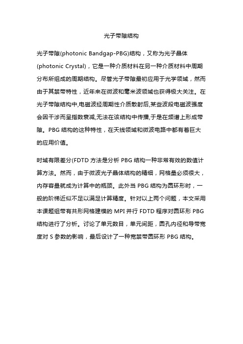
光子带隙(photonic Bandgap-PBG)结构,又称为光子晶体(photonic Crystal),它是一种介质材料在另一种介质材料中周期分布所组成的周期结构。
尽管光子带隙最初应用于光学领域,然而由于其禁带特性,近年来在微波和毫米波领域也获得极大关注。
在光子带隙结构中,电磁波经周期性介质散射后,某些波段电磁波强度会因干涉而呈指数衰减,无法在该结构中传播,于是在频谱上形成带隙。
PBG结构的这种特性,在天线领域和微波电路中都有着巨大的应用价值。
时域有限差分(FDTD方法是分析PBG结构一种非常有效的数值计算方法。
然而,由于微波光子晶体结构的精细,网格量必须很大,内存容量就成为计算中的瓶颈。
此外当PBG结构为圆环形时,一般的阶梯近似不足以满足计算精度。
针对以上两个问题,本文采用本课题组带有共形网格建模的MPI并行FDTD程序对圆环形PBG 结构进行了分析。
讨论了单元数目,单元间距,圆孔内径和导带宽度对S参数的影响,最后设计了一种宽禁带圆环形PBG结构。
Optic Fiber Fusion Splicer说明书

FEATURED TOPIC1. IntroductionAn optical fiber fusion splicer is an apparatus that instantly connects two fibers placed left and right on the apparatus by fusing the end surfaces of the fibers at a high temperature (approximately 1,800°C) created by arcing (Fig. 1).Compared to many other countries, optical fiber cable installation in Japan is highly advanced. As data communi-cation services for the home—Fiber-To-The-Home (FTTH)—become widely available, the people benefit from high capacity data transmission services for the Internet, television, and mobile communications. At the same time, optical fiber network construction is rapidly progressing across the world. This increases use of fusion splicers for installing backbone and FTTH networks, as well as in the assembly factories of fiber optic communication devices.Sumitomo Electric Industries, Ltd. started sales of its first fusion splicer, the TYPE-3, in 1980, and at that time the fusion splicer was designed only for multi-mode fiber (MMF/ITU-T G.651)*1. With this type of splicer, operators needed to splice the optical fibers while observing them in the V-shaped groove of the splicer through an attached microscope in order to accurately align the outer diameters of the fibers. The splice loss therefore depended on the operator's skill and experience, yet the MMF could still deliver a low splice loss thanks to its large core diameter and splicing with the fixed V-groove method. In 1982, Sumitomo Electric developed a new fusion splicer, the TYPE-11, to support the splicing of single-mode fiber (SMF/ ITU-T G.652)*2, which has a core diameter only one-fifth that of MMF. This splicer contributed to Japan's first instal-lation of fiber optic relay systems. The TYPE-11 fusion splicer was equipped with a fiber aligning mechanism having a light source and a light receptor at the far ends of each of the fibers to be spliced. With this mechanism, the fiber core was aligned at the point where the receptor detected the maximum amount of light from the light source. However, since the light source and the power meter had to be set up at locations some hundred meters or even several kilometers apart, splicing required rather too much prepara-tion and time. To work around such issues and achieve stable splicing, we developed the direct core monitoring tech-nology whereby the core is aligned by directly monitoring the fiber core through a microscope. This technology was originally developed for submarine cable installation but further evolved for use in land network installations.2. Optical Fiber Splicing T echnologies2-1 Optical fiber core direct monitoring technology Sumitomo Electric first employed the technology to directly monitor the optical fiber core in the TYPE-33 fusion splicer, which was launched in 1984. The TYPE-33 utilized a microscope equipped with a high-precision and-History and Vision of Optical Fiber Fusion SplicingT echnologyKensuke ITO*, Makoto MIYAMORI, Ryuichiro SATO, Hiroshi TAKAYANAGI, Hideaki YUSA, and Toshihiko HOMMA----------------------------------------------------------------------------------------------------------------------------------------------------------------------------------------------------------------------------------------------------------Sumitomo Electric Industries, Ltd. released the TYPE-3 fixed V-groove optical fiber fusion splicer for multi-mode fibers in 1980. Over the years, optical fiber fusion splicing technology has been making steady progress with the advancement of optical fiber production technology and the development of new jointing methods. This paper looks back at the history of splicing technology and highlights the technology that marked a crucial turning point in the progress. We also discuss our perspectives on how the technology can make further headway in the future.----------------------------------------------------------------------------------------------------------------------------------------------------------------------------------------------------------------------------------------------------------Keywords: optical fiber, fusion splicing, direct core monitoring, wireless LANAlign fibers Cleaning arcSplicingcompleted Splicing(Arc discharging)Opt icalfiberFig. 1. Arc fusion splicingBefore alignmentAfter alignmentAuto alignment Fiber coreFusion splicingFig. 2. Core alignment by direct monitoringhigh magnification object lens to observe the core of the optical fiber. The succeeding TYPE-34 adopted a CCD camera*3 for such monitoring. The camera automated the monitoring and alignment of the core of the optical fiber (Fig. 2), enabling stable fusion splicing with low splice loss.2-2 Downsizing and weight reductionThe TYPE-34 became larger in size and weight compared to its predecessors as it processed the image using a CCD camera, a circuit board, and a monitor.At the same time, as optical fiber networks became more widespread in Japan, cable installation sites also became diverse. Installation used to take place only in station buildings and cable tunnels but installation in the available space within sewerage tunnels and aerial distribu-tion became more common. Along with such changes in the installation environment, demand increased for fusion splicers to be smaller and lighter for better mobility.To respond to such needs, Sumitomo Electric devel-oped more compact and lighter products by employing a compact image sensor such as CMOS*4, dedicated LSI*5, and multi-layered high-density printed circuit board. In the latter half of the 1990s, the company started developing a battery-operated model to meet demand for usage in loca-tions where an AC power supply was not available. From 2000 onwards, compact, light, and battery-operated fusion splicers became Sumitomo Electric's mainstream products. 2-3 Environmental durabilityThe spread of optical fiber networks accelerated across the world and from this came increased demand for fusion splicers that could be used in harsh environments. In Japan, the splicers were required to be windproof so that they could be utilized at a height, such as at the top of pylons and electricity poles. While in other countries, more diverse weather durability was required, such as protection against higher and lower external temperatures, differences in elevation, dust, water, and shock. Nowadays, fusion splicers are required to be compliant with a range of stan-dard grades concerning operating environments, such as operating temperatures between -10°C and 50°C (storage temperatures between -40°C and 80°C), altitudes between 0 m and 5,000 m, and water and dust resistance. All of our fusion splicers meet such requirements. The shockproof capabilities of the splicers have been particularly improved through their size and weight reduction as well as the adop-tion of shock absorbers to reduce the impact transmitted to important components.The following sections describe the features of Sumitomo Electric's optical fiber fusion splicer technolo-gies and future prospects after 2000.3. Features of Sumitomo Electric's Optical FiberFusion Splicer T echnologies3-1 Dual heatersAfter the year 2000, with the increasingly widespread use of optical fibers, one of the issues associated with fusion splicing was the time needed to heat the splice protection sleeves used to reinforce the splice. At that time, splicing time was about 10 seconds, while the protection sleeve heating time required some 50 seconds. There arose demand to shorten the sleeve heating time for more effi-cient cable splicing work. The solution to this issue was the world's first dual heater mechanism, which was installed in our TYPE-39 splicer (Photo 1).Adoption of this dual heater mechanism eliminated the waiting time, which eventually led to the splicing tech-nique adopted in China, where multiple operators handle different tasks using a single fusion splicer. At the same time, the dual heater mechanism presented a new require-ment in fusion splicers: an increase in power capacity to operate the two heaters continuously. To work around this, Sumitomo Electric improved the heater structure to reduce the required heat capacity and increase thermal conducting efficiency to the splice protection sleeve. As a result, the protection sleeve heating time was reduced to 35 seconds. This in turn reduced the increase in the required power capacity to less than 20%, which also contributed to keeping fusion splicers compact in size.3-2 Automatic fiber profiling detectionTowards 2010, a bend insensitive fiber (BIF/ITU-T G.657) was introduced for home optical fiber cable instal-lation purposes. This fiber featured less optical power attenuation even when bent sharply. Fusion splicers were then required to handle this new fiber. Splice programs for BIF were different from those for single-mode fiber because the core of BIF is surrounded by holes and cladding with additional dopants*6. Thus, operators needed to vary splice programs depending on the type of optical fibers. The difficulty was that operators could not visually distin-guish SMF and BIF as they appear identical, so the opera-tors first needed to determine the fiber types using the attached specification documents. If they failed to identify the fibers and spliced them under the wrong program, the network quality was compromised due to increased splice loss and other defects. This prompted the need for fusion splicers to be able to detect the fiber type, set the optimum splice program, and then actually splice them all in an automated manner. Sumitomo Electric responded to this need with a new function that detects the optical fiber type from a processed image acquired through our exclusively high-magnification and high-precision object lens and camera technologies. When observing the profile of anoptical fiber at an optimum focusing distance, a certainPhoto 1. TYPE-39profile pattern of light and dark areas appears at the core. Sumitomo Electric's conventional fusion splicers identified the position of the core by processing an image of this pattern. Utilizing the fact that these light and dark profile patterns differ between SMF and BIF, an algorithm was developed to detect the optical fiber type and installed in a new model. This function enabled operators to deliver high-quality fusion splicing without having to manually confirm the optical fiber type.3-3 The world's smallest and lightest splicersCompactness and lightness of a fusion splicer are crit-ical in FTTH installations where efficient work in a limited space, such as on top of a pole, is essential. Sumitomo Electric's TYPE-25 compact fusion splicer had already enjoyed popularity thanks to its compactness and effi-ciency. However, needs for even smaller and more efficient splicers, a low-profile model in particular, increased due to requirements to splice fibers within a fiber enclosure. The company then redesigned the splicer structure by inte-grating control circuits that had been separated according to functions in previous models, and also by downsizing the monitoring equipment such as the object lens and camera. This led to the release of the TYPE-201 compact fusion splicer series (Photo 2) in 2013, which boasted the world's smallest and lightest body.3-4 Improvement in operabilityAround 2010, smartphones became even more popular in Japan as use of mobile devices accelerated thanks to their convenient touch screen operations. Accordingly, the user interface of various devices shifted from physical button operations to touch screen operations. This coincided with the time when fusion splicers' opera-tions became more complex to support diversifying optical fibers, making it necessary to further improve operability. In 2011, Sumitomo Electric released the TYPE-71 series (Photo 3), equipped with the industry's first touch screen, shifting the user interface from the conventional button-based input to more intuitive panel operations.Installing a touch screen to a fusion splicer faced diffi-culties in ensuring durability against weather, temperature, and shock, just as required by the splicer itself. We adopted reinforced glass, which is highly weather-proof and physi-cally durable, as the panel surface, and designed the struc-ture to be well sealed against dust and water. Thus, wecreated a touch screen that would withstand harsh outdoor use.Recent technological movements around Internet of Things (IoT) and Big Data have also influenced fusion splicers, creating a growing demand for the capability to record splicing work details, such as work dates, and splicing conditions and data. Furthermore, requirements for easy maintenance of data and functions for splicer operation management increased. In particular, ease in managing data on the fusion splicer as in a smartphone is becoming more important, and such data management functions include utili-zation of a massive volume of images and splice data, and batch update of software. To enable such data management operations, Sumitomo Electric released the TYPE-71C+ fusion splicer with a wireless LAN function in 2015.3-5 Fusion splice management systemDue to advancement of the Internet and telecommuni-cation technologies, IoT technologies are claiming society's attention. With this backdrop, Sumitomo Electric devel-oped the SumiCloud system (Fig. 3), which enables management of fusion splicer data over the Internet. The system stores and manages data, such as fusion splicing work details and work locations, which are shared betweenfusion splicers connected to the cloud server.Photo 2. TYPE-201 seriesPhoto 3. TYPE-71 seriesCloud serverSplicing siteWeb ser ver Dat abaseTYPE-71C+Wireless LANS mart phoneInt ernetProductio n Factor ySales o fficeUserFig. 3. SumiCloud system configurationUsing data management functions within the cloudserver, managers of fusion splicing projects can remotely view the installation status and fusion splicer conditions, check the splicing quality, and manage installation sched-ules in a more efficient manner.4. Future ProspectsTo build high-speed telecommunication infrastruc-tures, fiber cable installation will continue across the world. Various countries are competitively developing new gener-ation technologies, such as multicore fibers and other types of fiber development towards 5th generation communica-tions, and small-diameter super-multicore cables. It is important to establish fusion splicing technologies that can handle all types of optical fiber in order to realize more advanced optical communications. For this purpose, we continue our development of optical fiber direct monitoring technology and associated technologies.5. ConclusionThis paper has followed the history of optical fiber fusion splicing technologies and introduced the key devel-opments that have contributed to the evolvement of splicers. Sumitomo Electric continues to develop high-precision, high-performance, and highly-valued optical fiber fusion splicing technologies and offer them to the market.• S umiCloud is a trademark or registered trademark of Sumitomo Electric Indus-tries, Ltd.Technical Terms*1 M ulti-mode fiber/MMF: MMF is used for communication over short distance, such as LAN anddatacenter. The core of MMF has a refractive indexprofile gradually changing from the center of the coreto the cladding, which enables multiple of transmissionlight (mode) travel with nearly the same velocity.*2 S ingle-mode fiber/SMF: It is the most common optical fiber in the world. SMF is tuned to minimizethe dispersion (which gives the deformation to thesignal) around the wavelength at 1310 nm.*3 C CD camera: Charge Coupled Device camera.*4 C MOS: Complementary Metal Oxide Semiconductor *5 L SI: Large Scale Integration.*6 D opant: Materials mixed to attain an optimum refractive index distribution.Contributors The lead author is indicated by an asterisk (*). K. ITO*• G roup Manager, SEI Optifrontier Co., Ltd.M. MIYAMORI• A ssistant Manager, SEI Optifrontier Co., Ltd.R. SATO• A ssistant Manager, Optifrontier Co., Ltd.H. TAKAYANAGI• G roup Manager, SEI Optifrontier Co., Ltd.H. YUSA• D eputy General Manager, SEI Optifrontier Co., Ltd.T. HOMMA• Department Manager, SEI Optifrontier Co., Ltd.。
电子教材-两种新型一维微带开口环PBG结构

两种新型一维微带开口环PBG结构李玥冯全源(西南交通大学信息科学与技术学院,成都,四川,610031)摘要:本文在对一维光子带隙PBG(Photonic Bandgap)结构进行研究时,提出两种新型的开口环PBG结构,分别为圆形双开口环和方形双开口环两种结构。
两种结构均为在接地板上刻蚀周期性的开口环得到。
结果表明:圆形双开口环PBG结构简单易于实现,并且可以获得较宽的通带及较小的通带波纹。
方形双开口环PBG结构具有良好的通带特性,并且可以有效地改善通带的平坦度,减小插损,适用于微波及毫米波集成电路。
关键词:光子带隙结构;微带线;开口环中图分类号:TN925 文献标识码:ATwo Novel One-dimensional Photonic BandgapMicrostripline structure with Split Ring CellsLi Yue, Feng Quanyuan(School of Information Science & Technology, Southwest Jiaotong University,Chengdu, China, 610031)Abstract: This paper investigates and designs novel 1-D (one-dimensional) photonic bandgap(PBG) structures. It proposes two novel PBG structures with split ring cells including circular ringpattern with two splits and square ring pattern with two splits. They are all etched on the groundplane of the structures. Through theory analysis and simulation results, it shows that the PBGstructures with circular ring pattern are easy to realize and can get wide passband as well as smallripple. The square ring pattern with two splits shows good characteristic of passband and smallerripple within passband compared with circular ones. The square structure reduces the insertionloss and be used in MMIC.Keywords: Photonic bandgap; microstripline; split ring pattern一、 引言PBG(Photonic Bandgap)起源于对光子晶体的研究。
光电英语词汇汇总

光电英语词汇汇总photographic reconnaissance 照相侦察photographic recorder 摄影记录器,录相器photographic refractor 天体折射照相仪photographic reproduction 照相复制法photographic sensitometer 感光度测定仪photographic snesitivity 感光度photographic sound recorder 光录声机photographic standard irradiance 照相标准辐照度photographic tansmission density 照相透光密度photographic zenith tube 照光天顶管photography 照相术,摄影术photogravure 照相凹板印刷photogroduct 光化产品photogun 光电子枪photohalide 感光卤化物photohead 光电传感头photoheliograph 太阳照相机photoheliography 太阳照相术photohole 光穴photohyalography 光照蚀刻术photoimpact (1)光冲量(2)光控脉冲photoinactivation 光纯化作用photoinduced 光致的,光感生的photoinduced strain 光致应变photoinduction 光诱导,光感生photointaglio 照相板,影印版photointerpreter 相片判读装置photoionization 光致电离photoionization detector 光电离检测器photoionization threshold 光致电离阈photoisomer 光致同分异体photoisomerisom 光致同分异构photojunction cell 光电二极管photojunction diode 光电二极管photoklystron 光电速调管photolabile 对光不稳的photolayer 光敏层photolesn chromatism 摄影透镜色差photoline 光线photolithgraphic 光刻法的photolithography 光蚀刻微影; 光刻法; 平印照相制板photolocking 光锁定photology 光学photoluminescence 光致发光photoluminescence efficiency curve 光致发光效率曲线photolysis 光解作用photolyte 光解质photolytic 光解的photom 光度学photomacrogaph 宏观照片photomagnetic 光磁的photomagnetic effect 光磁效应photomagnetoelectric 光磁电的photomagnetoelectric effect 光磁电效应photomap 空中摄影地图photomask 光掩模photomask materials 光罩材料photomation 自体摄印相机photomatrices 光矩阵photomechanical 光学机械的photometallic etching 光金属蚀刻photometallurgical microscope 金相摄影显微镜photometeor 发光陨星photometer 光度计photometer bench 光度计座photometer head 光度计头photometers 光度计photometric 光度的photometric brightness 光亮度photometric brightness scale 光亮度标photometric calibration 光度校正photometric calibration data files 光度校准数据文件photometric computer 测光计算机photometric head 光度头photometric integrating sphere 光度积分球photometric method 光度测定法photometric paradox 光度佯谬photometric parallax 光度视差photometric period 光度周期photometric quality 光度质量photometric quantity 光度值,光度量photometric receiver 光度计photometric relationship 光度关系photometric repartition 光度分布photometric scale 光度标photometric standard 光度标准photometric standard lamp 光度标准灯photometric sterance 光辐通量photometric term 光度学术photometric test 光度检查photometric test plate 光度试验板photometric transfer function 光度传逊函数photometric units 光度学单位photometric wedge 测光楔photometry 光度学,光度测量术photomicrograph (1)显微照置(2)显微照片photomicrographic apparatus 显微照相装置photomicrographic tungsten arc lamp 显微照相钨弧光灯photomicrography 显微照相术photomicrometer 显微光度计photomicroscope 照相显微镜photomixer 光混频器photomixer diode 光混频二极管photomixing 光混频photomixing device 光源频器photomixing technique 光混频技术photomodulator 光调制器photomontage (1)光片剪辑(2)合成照片photomosaic 感光镶嵌幕photomotion 光激活动photomultiplier 光电倍增管photomultipliers 光电子增倍管(PMT)photomuon 光μ介子photon 光子photon absorption 光子吸收photon activated switch 光子起动开关photon amplification 光子放大photon annihilation 光子湮没photon avalanche 光子雪崩photon beam 光子束photon bombardment 光子轰系photon bunching 光子聚束photon capture 光子俘获photon counter 光子计数器photon counting spectrophotometer 光子计数分度计photon density 光子密度photon detector 光子探测器photon drag detector 光子牵引探测器photon drag photodetector 光子牵引光探测器photon effect 光子效应photon emission 光子发射photon excited atom 光子激发原子photon exitance 光子出photon fluctuation 光子起伏,光子波动photon flux 光子通量photon intensity 光子强度photon irradiance 光子辐射度photon liberation 光子逸出photon lifetime 光子寿命photon limited sensitivity 光子限灵敏度photon nosie 光子噪声photon radiance 光子辐射强度,光子辐射率photon statistics 光子统计学,光子流统计分布photon steradiance 光子辐射强度photon stream 光子流photon structure 光子结构photon-generated carrier 光生载流子photon-induced 光子感生的photon-induxed action 光子感生作用photonegative effect 负光电效应photonephelometer 光电浊度计photoneutron 光激中子photoneutron emission 光激中子发射photonic band structures 光子能带结构photonic band-gap (PBG) system 光能隙系统photonic bandgap 光子能隙photonic crystal 光子晶体photonic crystal fiber 光子晶体光纤photonic crystals 光子晶体Photonics 光电photonoise limit 光子噪声限photontransition 光子跃迁photonuclear disintegration 光致核蜕变photonuclear excitation 光核激发photooxidation 感光氧化用,光致氧化作用photooxygenation 光致氧化photooxygenation actinometer 光致氧化感光计photopeak 光巅,光峰photopen recorder 光笔记录器photoperiod 光周期photoperspectograph 摄影透视仪photophase 光相位photophobia 畏光症photophone 光电话,传真电话photophoresis 光致漂移photophysics 光子物理学photopia 光适应photopic eye 适光眼photopic range 适光范围photopic vison 亮视觉,白画视觉photoplane 摄影飞机photoplastic effect 光塑性效雁photoplastic material 光塑材料photoplastic recording 感光塑料记录photoplate 照相底片photopolymer 光聚合物photopolymer holography 光聚合物全息术photopolymerization 光聚作用photopositive 照相正片photopredissociation 光致预离解photoprigment 感光色素photoprint 影印,照页复制photoprocess 光学处理,光学加工photoproduction 光致作用,光生photoproducton cross-section 光致作用截面photoptometer 光敏计,光觉计photoptometry 辨光测验术photoradar 光雷达photoradiogram 光电传真电报photoransmitter 照片传真发器photoreaction 光致反应photoreader 光电读出器photoreading 光读婺photoreceiver 照片传真接器,光接收器photoreceptor 光感受器photorecombination laser 光复合激光器photoreconnaissance 摄影侦察photoreconversion 光致再转换photorecorder 摄影记录器,自动照明记录器photorectifier 光电检波器photoreduce 照相缩小photoreduction (1)光致还原(2)照相缩版photorefraction 光折射photorefractive 光致折变的photorefractive effect 光折射效应photorelay 光继电器photorepeater 复印机photoresist optics exposure 光电导曝光photoresistance 光敏电photoresistor 光敏电阻photoresistor-cell relay 光敏元件继电器photoresponse 光响应photoresponsive retina 光响应视网膜photoresponsive tube 光响应管photorproton 光质子photoscanning 光扫描photoscope 透视镜photosensing units 光感测元件photosensitiser 感光剂,光敏剂photosensitive 光感的,感光的photosensitive area 光敏区,光敏面积photosensitive device 光敏器件photosensitive film 光敏膜photosensitive glass 光敏玻璃photosensitive layer 光敏层photosensitive material 感光材料photosensitive medium 光敏媒质photosensitiveness 光敏性,光敏度photosensitivity 光敏性,感光性,感光灵敏度photosensitization 光敏作用photosensitizer 光敏剂photosensor 光敏器件photoseparation 光分离photoset 照相版排photosignal 光信号photosource 光源photosphere 光球层photospot 聚光photostability 耐光性photostable 不感光的,耐光的photostar 发光星体photosterograph 立体测图仪photostimulaton 光剌激photostudio (1)照相馆(2)摄影棚photosurface 光敏面photosurface spectral response 光敏面光谱响应photoswitch 光开关photosynthesis 光合作用phototaxis 趋光性phototelegram 传真电报phototelegraph 传真电报phototelegraphy 传真电报术phototelephone 传真电报机phototelephony 传真电话术phototelescope 照相望远镜phototherapeutics 光线治疗学phototherapy 光线疗法photothermionic image converter 光热离子变相管phototimer (1)曝光计(2)摄影计时器(3)延时光控继电器phototiming 光同调步phototransistor 光电晶体管,光敏三极管phototransistors 光电晶体phototransmutation 感光蜕变phototriode 光电三极phototroller 光控电管phototron 矩阵光电管phototrop 光色互变phototropic 向光的phototropic vision 摄影仪phototropism (1)趋光性,向光性(2)光色互变现象phototube 光电管phototubes 光电管phototype 珂罗版phototypesetter 照相排字机photounit 光电件photovalue 光阀photovaoltaic 光生伏打的photovisual objective 拟视照相物镜photovisula achromatism 光化视觉消色差性photovolt desitometer 光电密度计photovoltage 光电压photovoltaic 光生伏打photovoltaic cell 光生伏打电池photovoltaic converter 光伏变换器,光电能量变换器photovoltaic effect 光生伏打效应photovoltaic infrared detector 光伏红外探测器photox cell 氧化亚铜光电元件photoxide 光氧化物photozincograph 照相锌版photsyntometer 光合计phrolysis 高温分解,热解phromagnetic 热磁的phromagnetic detection 热磁探测phse-modulated signals 调相信号phse-modulated waves 调相波phthalocyanin 屻花悄phtoochromatic filter 光致变色滤光器physi-optics 物理光学physical absorption 物理吸附Physical chemistry 物理化学physical constraint 物理约束physical development 物理显影physical entropy 物理熵physical interpretation 物理解释physical optics 物理光学physical photometer 物理光度计physical photometry 物理光度测量学physical quantity 物理量physical thickness 物理厚度physics 物理学physiological 生理的physiological blur 生理模糊斑physiological model 生理模型physiological optics 生理光学physiological photometer 生理光度计physiology 生理学physioptial 物理光学的pic (1)图片,照片(2)图画,图像pic-up device 摄像装置pick-off diode 截止二极管pick-off gear 可互换齿轮pick-up (1)拾波,拾声(2)拾波器(3)拾声器(4)传感器(5)电视摄像管pick-up camera 摄像机pick-up head lenses 光碟机读取头透镜pick-up system 摄像系械pick-up tube 摄像管pickoff (1)传感器,探测器(2)截止(3)拾取pickoff couple 截止耦合器pickoff unit (1)接收器(2)截止器piclear unit 图像清除器picling (1)酸浸(2)浸渍picnometer (1)比重瓶(2)比色计pico 皮picosecond (ps)微微秒picosecond light pulse 微微秒光脉冲picosecond pulse 微微秒脉pictorial display 图像显示pictorial holography 图像全息术pictorial infrared photography 红外图像照相术pictorial view 示图,插图picture (1)画,图像(2)图片,照片picture bit rate 图像位速率picture element 像素,像元picture field 图像场picture frequency 图像频率picture image 图像picture jump 图像跳动picture pattern 图像,图样picture processing 图像处理picture quantizer 图像数字转换器picture retention 图像残留picture signal 图像信号picture signal amplitude 图像信号振幅picture synchronization 图像同步picture taking wavelength 摄影波长picture transmission camera system 图像传输摄影机系统picturephone 电视电甘picturephone set 电视电话机piecewise interferometric generation 分段傅里叶谱pieometer 压力计,压强计piercing 分段干涉量度振荡piezo 钻孔piezo-luminescence 压难发光piezo-optical coefficient 压光系数piezo-optical property 压光性质piezocrystal 压,压力piezoelectric 压电晶体piezoelectric ceramic 压电的piezoelectric constant 压电陶瓷piezoelectric crystal 压电常数piezoelectric effect 压电晶体piezoelectric laser modulation 压电现像,压电学piezoelectric light modulator 压电激光调制piezoelectric matrix 压电光调制器piezoelectric positioning equipment 压电定位设备piezoelectric quartz crystal 压电矩阵piezoelectric resonator 压电石英晶体piezoelectric tensor 压电共振器piezoelectric transducer 压电换能器piezoelectric transformer 压电变压器piezoelectric vibration 压电振动piezoelectricity 压电效应piezoid 压电石英piezometric 量压的,测压的piezometry 压力测定piezoquartz 压电石英piezoresistance 压敏电阻piezoresistive 压缩电阻的piezoresistor 压敏电阻器pig iron 生铁pigment (1)色素(2)颜料pigment epithelium 色素层pile-of-plates polarizer 玻片堆偏振器pile-up (1)堆积效应(2)堆集,聚集,积累pillar 柱,墩pillbox antenna 抛物柱面天线pillbox distribution 抛物柱面分布pillow (1)枕块(2)轴枕pilot ballon theodolite 气球测风经纬仪pilot lamp 指示灯pilot light 指示灯pilot wave 领波pimpling 凸起pin (1)别针(2)销钉(3)插头(4)管脚pin clamp 插销口pin photodiode 针状光电二极管pin photodiode modules for communication 通信用PIN光二极体模组pin photodiodes for communication 通信用PIN光二极体pin-camera 针孔照相机pin-electrode 针状电极pin-electrode discharge technique 针极放电技术pinacoid 轴面pinch 箍缩pinch effect 箍缩效应pinch laser 箍缩激光器pinch plasma 箍缩等离子体pinch pump 箍缩泵pinch-discharged-pumped laser 箍缩收电抽运激光器pinch-off effect 箍断效应pinch-off voltage 箍断电压pinch-preheated 收缩预热的pincushion aberration 枕形像差pincushion distortion 枕形失真pincushion-shaped image 枕形像pinhole 针孔,小孔pinhole camera 针孔照相机pinhole filter 针孔滤波器pinhole filters 针孔滤光镜pinhole image 针孔像pinhole imaging 针孔成像pinhole photography 针孔照相术pinhole system 针孔系统pinholes 针孔pinion 小齿轮,副齿轮pinion shaft 齿轮轴pink 淡红色的,纷红色的pinning (1)阻塞(2)闭合pinor 自旋量pinpoint (1)针尖(2)空中精确摄影(3)航空照片(4)精确定位pinpoint accuracy 高精确度pinpoint technique 精密技术pinpointed focus 定位焦点pint 品脱pip (1)针头(2)反射点(3)针头信号(4)广播报时信号pipe (1)管,导管(2)管状物pipe cross 十字接头,交接头pipeline (1)管道(2)输送管piping (1)管系(2)导管piquant 图佣数字转换器Pirani gage 皮剌尼计piston 活塞pit 凹痕,麻点pitch (1)螺距,齿节间距(2)沥青(3)松鲁(4)音调pitch adhesive 沥青黏结剂pitch angle 俯仰角pitch control (1)色调控制(2)音调控制pitch error (1)螺距误差(2)周节误差pitch gage (1)螺距规(2)周节仪pitch lap 沥青抛光盘pitch line (1)中心线(2)分度线pitch polishing tol 沥青抛光模pitch viscosity 沥青黏度pitting (1)凹痕,麻点(2)锈斑pivot (1)枢纽(2)支轴(3)支点pivot bearing 枢轴承pivot lesn apparatus 旋转透镜装罝pivot pad 枢轴垫,心轴垫pivot screw 枢轴螺钉pivot-point 支点pivoted axle 转动轴,摆动轴pixel 像素,像元placement 方位,部位,位置Placideo's disk 浦拉西多盘,角膜镜plain bearing 普通轴承,滑体轴承plain view drawing 平面图plan (1)计划(2)平面图,设计图plan of site 总布置图plan view 平面图,俯视图planar access couple 平面存取耦合器planar array 平面阵列planar dielectric waveguid 平面介质波导planar epitaxial phototransistor 平面外延光电晶体管planar hologram 平面全息图planar iris 平面可变光阑Planar lens 普拉纳镜头planar mirror 平面反射镜planar mosaic array 平面镶嵌阵列planar optical waveguide 平面光波导planar phottransistor 平面光电晶管planar rotor 平面转动片planar stripe DH laser 平面条状DH激光器planar waveguide-type 平面波导型planar-diffused transistor 平面扩散晶体管Planck function 普朗克函Planck's blackbody law 普朗克黑体定定律Planck's constant 普朗克常数Planck's holhrum radiaton 普朗克空腔辐射Planck's law 普朗克定徭Planck's oscillator 普朗克振子Planck's radiation law 普朗克辐射定且Planck's spectral radiation formula 普朗克光谱辐射公式Planckian locus 普朗克轨迹Planckian radiator 普朗克辐射体plane (1)平面(2)程度,水平(3)飞机(4)平面的plane angle 平面角plane cam 平面凸轮plane cocular 平场目镜plane goniometer 平面测向计plane grating 平面光栅plane hologram 平面全息图plane interference 平面干涉plane mirror 平面反小镜plane monchromator 平面色器plane of field lens 场镜面plane of incidence 入射面plane of oscillation 振动面plane of polarization 偏振面plane of projection 投影面plane of reflection 反射面plane of refraction 折射面plane of sharpest focus 最锐聚焦面plane of symmetry 对面plane of vibration 振动面plane optical flat 平面光学平晶plane polariscope 平面偏振镜plane polarization wave 面振波plane polarized (1)面振的(2)平面极化的plane polarized laser beam 平面偏振激光束plane polarized wave 面振波plane polarizedl ight 面振光plane position indicator (PPI)平面位置指示器,平面示伅器plane resonator 平面型共振器plane rod end 棒端面plane section 剖面plane shape irdome 平面型红外整流罩plane shutter 平面快门plane spatial filter 平面空间滤波器plane surface 平面plane surveying 平面测量plane wave 平面波plane wave front 平面波前plane-grating spectrograph 平面光栅摄谱仪plane-paralledl cavity 平行平面共振腔plane-parallel mirror 平行平面反射镜plane-parallel resonator 平行平面共振器plane-table alidade 平板照准仪plane-table survey 平板测planeness 平度planet 行星planetarium (1)天文馆(2)天象仪(3)太阳系仪planetarium projector 天象投影仪planetary (1)行星的(2)行星齿轮的planetary mission 行星齿轮变速管planetary pinion 行星小齿轮planetary radiation 行星辐射planetray microfilmer 文献资料翻拍机planetray reducer 行星减速齿轮planigraphy 层析X射线照相法planimegraph 面积比例规,缩图器planimeter (1)面积仪(2)求积仪planimetry 测面学,平面几何planitron 平面数字管planizer 平面授描头,平面发生器plank 板,厚板plano-aspheric corrector 平板非球面校正镜「施密特校正镜plano-aspheric transmitting corrector 平面非球面透射校正镜plano-concave lens 平凹透镜plano-convcave 平凹的plano-convex 平凸plano-convex lens 平凸透镜planometer 测平面仪,平面规planopaallel plate 平行平面板,平行平晶planoscope eyepiece 平场目刽planox 平面氧化的plant (1)成套设备(2)站(3)工厂,车间plariser 偏振器,偏振片plasma 等离子体,等离子区plasma -speetrometer 等离子光谱仪plasma arc pumping 等离子体电弧抽运plasma channel 等离子体通道plasma column 等离子体柱plasma corona 离子体电晕plasma CVD equipment 电浆CVD设备plasma density profile 等离子密度分布plasma dignostics 等离子体诊断Plasma Display Panel (PDP)电浆显示器plasma display panels (PDP)电浆显示器plasma ejection 等离子体抛射Plasma Enhance Chemical Vapor Deposition (PECVD)电浆增强式化学气相沉积法plasma exciatiaon 等离子体激发plasma focus 等离子焦点plasma frequency 等离子体频率plasma generation with laser 激光产生等离子体plasma generator 等离子体发生器plasma laser 等离子体激光器plasma light source 等离子体光源plasma oscillation 等离子体振荡plasma parameter 等离子体参数plasma pinch pump 等离子体箍缩泵plasma polymerization 等离子体聚合plasma polymerized coating 等离子体聚合涂层plasma polymerized thin film 等离子体合薄膜plasma radiation 等离子体辐射plasma reflectivity 等离子体反射率plasma slab 等离子层plasma spatial filter 等离子体空间滤光片plasma sphere 等离子层plasma torch 等离子火焰plasma tube 等离子体管plasma wave 等离子体波plasma-overlap laser 等离子体并行激光器plasma-pump laser 等离子体泵激光器plasma-sheet CO2 laser 等离子体薄板CO2激光器plasmat-type copying lens 等离子型仿徵透镜plasmatron 等离子管,等离子流发生器plasmoid 等离子体粒团plasmon 等离子体激元plaster (1)熟石膏(2)硬膏plaster block 石膏镜盘plaster of Paris 熟石膏,烧石膏plastic (1)塑料的(2)塑性的,范性的(3)塑料plastic aspheric lenes 塑胶非球面透镜plastic cement 塑料胶plastic clad fiber 塑料色层纤维plastic deformation 塑或变形plastic dye laser 塑料染料激光器plastic ferrules 塑胶箍(套管)plastic fibre optics 塑料纤维光学plastic film 塑料薄膜plastic filters 塑胶滤光镜plastic focusing fibre 塑料聚焦纤维plastic laser 塑料激光器plastic lens system 塑料透镜系统plastic material (1)塑料(2)可塑材料,塑性材料plastic optical fiber 塑料光学纤维plastic optics 塑料光学纤维plastic polishing 成型抛光plastic Q switch 塑料Q开关plastic recoding medium 塑性记录媒质plastic shim material 塑性垫片材料plastic spectacle lens 塑料眼镜片plastic spheric lenes 塑胶球面透镜plastic-base mirror 塑料底座镜plasticien 代用黏土plasticity (1)可塑性,范性(2)黏性plasticization 增塑plasticizer (1)增塑剂(2)增韧剂plastics 塑料,塑胶plasto-elasticity 弹塑性力学plastyle lens 塑玻透镜plate (1)盘(2)片(3)薄反(4)板极(5)底片plate camera 干板照相机plate glass 玻璃板plate holder 干板照拿plate let laser 小片激光器plate level 盘式水准器plate level vial 盘水准管plate library 底片库plate object 板状plate potential 板极电势,板极电位plate theory 薄板理论plateau 背脊platelet 薄片,小片platform 平台,站台plating 镀,电镀plating bath 镀金槽,电镀槽platinotron 泊管platinum (Pt)铂platinum black 铂黑platinum bolometer 铂测辐射热计platinum crucible 铂金坩埚platinum mirror coating 铂镜面镀层platinum oxide 氧化铂play (1)隙,隙缝(2)闪晃play-off beam 回扫射束playback 播收pleochroic 多向色的pleochroic halo 多向色晕圈pleochroism 多向色性,多色性Pleon lens 普来昂镜头plexiform layers 胶木板Plexiglass 普莱有机玻璃Plexiglass diffuser 普莱有机玻璃漫射体pliability 可挠性pliotron (1)功率三极管(2)空气过滤器pllane glass 平面玻璃,平板玻璃pllarising microscope in reflected light 反射光偏振微镜Plochere color system 普罗彻尔彩色系统Ploessl eyepiece 普罗爱瑟目镜,对称性目镜plot (1)标甥(2)标甥图plot diagram 点列图plotomat 自动绘图机plotter 标绘器,绘迹器plotting instrument 绘图仪器plotting objective 纠正仪物镜plotting tablet 标图板plug 插头,插塞plug gage 塞规plug screw gauge 螺纹塞规plug-in (1)捏入式的,组合式的(2)捏座plug-in unit 插件plugs 插头plumb 铅锤,垂直plumb aligner 铅锤对准器plumb level 水准仪,水平仪plumb line 铅垂线,重垂线plumb line deviation 垂线偏差plumbago 石墨,炭精plumbico camera tube 氧化铅光电导摄管plumbicon 氧化铅摄像管plumbing mirror 垂准镜plumbum (Pb)铅plummet (1)铅垂球(2)铅垂线plunger (1)柱塞(2)短路器plurality (1)多元(2)多数(3)复数plus (1)正号(2)加号(3)正数(4)正的(5)加plus lens 正透镜plus power spherical lens 正屈光度球透镜plus sphero-cylinder 正球柱透镜Plustar lens 普鲁斯特拉物镜plutonium (Pu)鐶PLZT display device PLZT显示装置PLZT wafers PLZT晶圆,钛酸锆酸铅晶圆PM-LCD Passive Matrix LCD被动式矩阵液晶PME-effect 光磁电效应pmmersion oil 浸油pneumatic 空气的,气动的,气力的,风力的pneumatic detector 气动检测器pneumatics 气体力学Pockels' cell 泡克耳斯拿Pockels' cell apodizer 泡克耳斯切趾器Pockels' device 泡克耳斯器件Pockels' effect 泡克耳斯效应Pockels' effect cell 泡克耳斯效应拿Pockels' readout optical nidulator (PROM)泡克耳斯读出光学调制器Pockels' shutter 泡克耳斯光闸pocket (1)袋,袋状物(2)袖珍的pocket camera 袖珍相机pocket compass 袖珍罗盘pocket microscope 袖珍显微镜pocket sextant 袖珍六分义Pohl interferometer 坡耳干涉仪Poincare sphere 鲍英卡勒球point (1)点(2)小数点(3)尖端point angle 顶角point brilliance 点耀度point caracteristic funtion 特微函数point defect 点缺陷point function 点函point object 点物point of fixation 注视点point of fusion 融汇点point of incidence 入射点point of inflexion 拐点,变曲点point of intersection 交点point of reference 参考点,基准点point particle 质点point projector microscope 点投射显微镜point sampling 点取样法point sighted 瞄准点point source 点光源point source lamp 点光源灯point source radiator 点源辐射器point spectrum 点谱,离散谱point spread function 点扩散函数point symetry 点对point symmetry groups 点对群point-by-point reproduction of the object 逐点再现物体point-by-point scanning 逐点扫描point-by-point storage 逐位存储point-contact photodiode 触光电二极管point-foussed 聚於一点的point-source hologram 点光源全息图point-to-point image 成点pointed 尖的pointer (1)指针(2)指示器pointing (1)削尖,弄尖(2)瞄准pointing accuracy 瞄准精度pointing error 瞄准误差pointing technique 瞄准技术pointolite 点光产pointolite lamp 点光源灯points of the compass 罗盘上方位罗Poisson diffraction 泊松衍射Poisson distribution 泊松分布Poisson's ratio 泊松比polanret microscope 变偏光相差显微镜polar angle 极角polar axis 极轴polar axis shaft 极坐标轴polar bond 极性polar compound 极性混合物polar corrdinates 极性标polar crystal 极性晶体polar diagram 极性坐标图polar distribution 极角分布polar light 极光polar molecule 有极分子,极性分子polar mosaic 极性镶嵌polar plot 极线图polar symmetry axis 极性对轴polar telescope 北极管polar vector 极矢polarimeter 偏振光计,偏振光镜polarimeters 偏振计polarimetric 测定偏振的polarimetric element 测振元件polarimetry 旋光测定法,测偏振术polarisation interferometer 偏振干涉仪polariscope 旋光计,偏振镜polariscopes 偏振光镜polarising metallurgical microscope 偏振金相显微镜polarising microscope in transmitted light 镜射光偏振显微镜polariton 电磁激子polariton scattering spectrum 电磁激子散射谱polarity 极性polarity detector 信号极生探测器polarizability (1)极化性(2)极化率polarizability ellipsoid 极化性椭球体polarizable 可极化polarizaiton of laser output 激光输出偏振度polarization (1)偏振(2)标定polarization analyzer 检偏器,检偏镜polarization degeneracy 极化简并度polarization effect 偏振效应polarization ellipse 偏振椭圆polarization error 极化误仪,偏振误差polarization factor 偏振因数polarization filter 偏振滤光器,偏振镜polarization hologram 偏振全息照片polarization interference microscope 偏光干涉显微镜polarization interferometer 偏振干涉仪polarization junction laser 偏振结型激光器polarization microscope 偏光显微镜polarization modulation 偏振调制polarization of light 光偏振polarization of sky light 天光偏裁polarization optics 偏振光学polarization photmeter 偏振光度计polarization reversal 极化又射polarization rotation (1)偏振旋转(2)极化旋转polarization selectivity 偏振选择性polarization tensor 极化张量polarization vector 偏振矢量polarization-rectifier obejctive 偏振整流物镜polarization-resolving optics 偏振光学分离器polarization-rotated reflection 偏振转反射polarizational labelling 偏振标定polarizationally isotropic cavity 偏振各向同性腔polarized headlight 偏振前车灯polarized light 偏振光polarized light microscope 偏振光显微镜polarized light modulation 偏振光调制polarized line 振线polarized radiation 极性辐射polarized specrophotometer 偏振分光光度计polarized wave 偏振波polarized-light optical system 振光光学系统polarizer 偏光板polarizer-Kerr-cell combination 偏振镜-克尔盒组合polarizer/ phase shift layer 偏光板/相位差板polarizers 偏光镜polarizign coil 极化线圈polarizing 起偏振polarizing angle 起偏抚角polarizing color filter 偏振彩色滤光片polarizing electrode 极化电极polarizing eyepiece 起偏振目镜polarizing filter 偏振滤光,起偏滤光polarizing filters 偏光滤光镜polarizing glass 偏光镜,偏振目镜polarizing itnerferometer 偏振干涉仪polarizing microscope 偏光显微镜polarizing microscopes 偏光显微镜polarizing mirror 偏光反射镜polarizing optics 偏振光学装置polarizing plate 起偏振光片polarizing prism 偏振棱镜,起偏棱镜polarizing shearing itnerferometer 偏振剪切干涉仪polarizing spectrohotmeter 偏振分光光度计polarizing waveplate 偏光波板polarizse (1)偏振(2)极化polarogram 极谱polarographci wave 极谱波polarographic analysis 极谱分析法polarographic method 极谱法polarography 极谱法polaroid (1)偏振片(2)即显胶片Polaroid camera 波拉一步照相机polaroid film 即显胶片polaroid filter 人造偏振片滤光器polaroid foil 人造偏振箱polaroid glass 偏光镜,偏振目镜polaroid polarizer 偏振片,偏振镜polaroid sheet 偏振片polaroid vectorgarph (1)偏振立体镜(2)立体电影polaron 极化子polarotactic navigation 偏振光导航polarotaxis 趋偏光性polaxis 极化轴pole (1)极(2)电极(3)磁极(4)极点(5)棒,杆pole figure 极像图pole gap 极隙pole piece 极片pole strenght 磁极强度pole-change 极变换polgrogaph 极谱仪poling 成极,单畴化polish (1)抛光(2)抛光剂polisher 抛光机polishing block 抛光盘polishing compound 抛光剂polishing compounds 研磨化合物polishing damage 抛光损伤polishing machine 抛光机polishing material 抛光材料polishing pads and cloth 研磨衬垫及布polishing plastic 抛光塑料polishing powder 抛光粉polishing rouge 抛光红粉polishing tool 抛光模politure 抛光polka-dot method 圆点光栅法pollutant 污染物pollution 污染pollution control 污染控制poloidal field 角向场poloniqum (Po)钋polsihed-barrl-rod 抛光圆棒polsihing felt 抛光毡子polsihing lap 抛光盘poly-lens objectie 多透镜物镜poly-silicon TFT LCD 多晶矽TFT LCD 液晶面板polyalkyl methacrylate 聚甲基丙烯酸烷基酯polyallyl metacylate 聚甲基丙烯酸烯丙酯polyamide 聚酸胺polyatomic 多原子polyatomic chemical laser 多原子激光器polyatomic system 多原子系统polycarbonate 聚碳酸酯polychormism 多组元polychroism 多色polychromatic 多色的polychromatic field 多色场polychromatic light 多色光,多色灯polychromatic radiation 多色辐射polychromatic radiator 多色辐射器polychromatic source 多色光源polychromatic wave 多色波polychromatism 多色polychromator 多色仪polychrome 多色性polycomponent 多晶体polycrystal 多晶的polycrystalline 多晶区polycrystalline area 多晶硫族化物polycrystalline chalcogenide 多晶纤维光学波导polycrystalline fibre optical waveguide 多晶锭块polycrystalline ingot 多晶激光器polycrystalline lawer 多晶物质polycrystalline material 多晶体散射polycrystalline scattering 多晶半导体polycrystalline semiconductor 聚甲基丙烯酸环已酯polycyclohexyl methacrylate 聚邻本二甲酸二烯丙酯polydiallyl itaconate 聚衣康酸二甲酯polydisperse 多色散polydisperse aqueous aerosol 多色散水气悬体polydisperse particulate system 多色散粒子系统polyemid 配向膜polyester 聚酯polyester fiber 聚酯纤维polyester-styrene 聚酯本乙烯polyethylen 聚乙烯polyethylene dimethacrylate 聚乙烯二异丁烯polyfoam 泡洙塑料polyglas 本乙烯塑料polygon 多形,多角形polygonal 多边形的,多角形的polygonal mirror 多面镜,光学夕面体polygonal mirrors 多面镜polygonal prism 多边形棱镜polyhedral 多面的polyhedron 多面体polyisobutylene 聚异乙烯polymer 聚合物Polymer processing 高分子加工Polymer science 高分子材料polymeric thin film 聚合薄膜polymerization 聚合作用polymerization transition 聚合变化polymerized 聚合的polymerized diacthylene 聚合丁二炔polymethacrylate 聚甲基丙烯酸酯polymethacrylic acid 聚甲基丙烯酸polymethine 聚甲炔polymethine dye laser 聚甲炔染料激光器polymethine Q switch 聚甲炔Q开关polymethyl methacrylate 聚甲基Polymethylmethacrylate diagnostic contact lens 诊疗用PMMA角膜接触镜片PMMA diagnostic contact lens 诊疗用PMMA角膜接触镜片polymorphism 聚甲基丙炔酸甲酯polynomial 同质多晶型polyphase 多项式多相polyphase current 多相电流polyplanar 多晶平面polypropylene 聚丙烯polyriboadenylic acid 多核糖腺甘酸polysilicon 多晶硅polystyrene 聚本孔烯polystyrene diffusion broadening 聚本乙烯扩展宽polytetrafluoethane 聚四氟甲烷polytetrafluorethylene (PTFE)聚四氟乙烯POLYTHENE FILM 聚乙烯polytroic 多方的polytype 多型体polyurethane 聚氨基甲酸醴polyvalence 多价polyvinyl 聚孔烯polyvinyl alcohol 聚孔烯醇polyvinyl chloride (PVC)聚氯孔烯polyvinyl chloride film 聚氯孔烯软片polyvinyl naphthalene 聚乙烯基本polyvinyl-fluoride 聚氟乙烯polyvinylcyclohexene dioxide 聚孔烯环已烯二氧化物polyvinylidene fluoride 聚偏氟乙烯ponderability 可称性,有质性pony axle 空转轴,导轴poop 尖锐脉冲poor focus 不银聚焦poor light condition 微光条件popular inversion area 粒子数反转区populated 粒子数增加的population (1)布居(2)粒子数population density 粒子数密度population difference 布居差population distribution 粒子数分布population hang-up 粒子数悬布population inversion 粒子数反转population mean 总体平均值population of level 能级个数,能级填满数population of parameter 参数组population ratio 粒子数比population risetime 粒子数增长时间population threshold 粒子数阈值porcelain 瓷器porcelain enamel 搪瓷porcelain insulator 瓷绝绿体porch 边缘pore 细孔pore diameter 孔径pore structure 细孔结构,毛孔结构porime focus 主反射镜焦点poriness 多孔性porosint 多孔材料porosity (1)多孔性(2)孔隙率porosu solid 多孔固体porous 多孔的porous cladding 多孔包层porous glass 多孔玻璃porous material 疏松材料porphyrin 咐林Porro prism 波罗棱镜Porro prism erecting system 波罗镜正像系统Porrotelescope 波罗望远镜。
- 1、下载文档前请自行甄别文档内容的完整性,平台不提供额外的编辑、内容补充、找答案等附加服务。
- 2、"仅部分预览"的文档,不可在线预览部分如存在完整性等问题,可反馈申请退款(可完整预览的文档不适用该条件!)。
- 3、如文档侵犯您的权益,请联系客服反馈,我们会尽快为您处理(人工客服工作时间:9:00-18:30)。
October15,2004/Vol.29,No.20/OPTICS LETTERS2369 All-solid photonic bandgap fiberF.Luan,A.K.George,T.D.Hedley,G.J.Pearce,D.M.Bird,J.C.Knight,and P.St.J.RussellDepartment of Physics,University of Bath,Bath BA27AY,UKReceived June22,2004We describe the design and fabrication of a photonic bandgap fiber formed with two different glasses.As ina hollow-core fiber,light is guided in a low-index core region because of the antiresonances of the high-indexstrands in the fiber cladding.The structure described represents an ideal bandgap fiber that exhibits nointerface modes and guides over the full width of multiple bandgaps.©2004Optical Society of AmericaOCIS codes:060.2270,060.2280,060.2310.Hollow-core photonic crystal fibers(HC-PCFs)in which light is guided by a photonic bandgap cladding material have attracted great interest in recent years.1–3Most reported HC-PCFs consist of a central air core surrounded by a periodic array of air holes in a silica background.When the air holes in a HC-PCF are large,the structure resembles a honeycomb array of thin silica strands supported by a mesh of even finer webs.This structure is a compromise between performance and feasibility.The fiber performance would be improved if the connecting webs of silica were thinner or were completely absent,but such a structure is not self-supporting.In the simpler case of an array of unconnected high-index rods in a low-index background,the bandgaps of the cladding are easily seen to arise from the antiresonance of each individual high-index cladding rod.4Such fibers have been demonstrated5–7by putting high-index f luid into a short length of standard solid-core silica–air photonic crystal fiber.8,9However,those fibers are hard to use and have an intrinsically limited length, as well as being unstable to temperature and other environmental effects.In this Letter we report the realization and characterization of a similar fiber based on two thermally matched silicate glasses.Our fibers are practical and stable and can be readily drawn down for access to the fundamental bandgap. They provide an ideal system to study the basic features of photonic bandgap guidance,which are complicated in hollow-core fibers by interface-mode effects.2The structure that we have studied is a two-dimensional triangular array of high-index rods (refractive index n11.79)embedded in a low-index background(index n21.54).Computations havebeen performed with a variation of the plane-wave method10in which we compute the photonic states occurring in a range of values of the propagation constant b(the wave-vector component along the fiber axis)for a fixed free-space propagation constant k0.Figure1is a bandgap diagram based on the computed density of photonic states10for three arrays of circular high-index rods͑n11.79͒of the same diameter but spaced by different amounts in a low-index matrix͑n21.54͒.The scaling of the y axes is normalized by rod diameter d,while the x axis shows ͑b22n22k02͒d2,so that the glass line representing the cutoff for the continuous core material n2appears as a vertical line at zero.11The most obvious feature of the these plots is that the frequency of the funda-mental bandgap remains approximately unchanged even though the pitch of the array has changed by a factor of3,direct evidence that the mechanism behind bandgap formation is antiresonances of the individual rods.Although the pitch does not(to first order)change the bandgap frequency,it does affect the shape and depth of the bandgap as a result of the changing coupling strength.In moving from Fig.1(a) to Fig.1(c)the bandgap gets narrower and deeper, which will affect the confinement of waveguiding fibers designed using this type of cladding.To realize the above structure we used two ther-mally compatible silicate glasses,LLF1and SF6 from Schott Glass,Ltd.LLF1has an index near 1.54at visible and near-IR wavelengths,while the index of SF6isϳ1.79.Similar glasses were used in recently reported work12to make index-guiding photonic crystal fibers.In this demonstration we used a multiple-stacking method in which each SF6 rod was surrounded by6LLF1rods.The central area,which would have contained7SF6rods and12 LLF1rods,was replaced with one big LLF1rod to form the core.The stack was drawn to fiber in two drawing stages,between which a thick SF6jacket was added.Figure2(a)shows a backscattering image of the endface of a fiber taken with a scanningelectron Fig.1.Bandgap plots of the same size rods placed at dif-ferent distances,with the white regions having zero den-sity of photonic states.The background index was set to n21.54,and the index of the rods was n11.79.0146-9592/04/202369-03$15.00/0©2004Optical Society of America2370OPTICS LETTERS/Vol.29,No.20/October15,2004Fig.2.(a)Backscattered electron images of the all-solid photonic bandgap fiber.The black structure is the LLF1 rods and the white areas are the SF6rods.(b)Measured near-field patterns of guided modes.A3-nm bandpass fil-ter was used at the input.The wavelengths for the top and bottom images were690and575nm,respectively. The transmission spectrum of the fiber sample is shown in Fig.4(a),below.microscope.The bright white regions are SF6,and the dark areas are LLF1.Observed near-field images of guided modes in this fiber are shown in Fig.2(b). During drawing,the SF6rods turn into star shapes, because at the drawing temperature SF6is softer than LLF1.Figure3presents numerical simulations of an array of star-shaped high-index rods derived from electron microscope images of real fibers,demon-strating that the shape of the high-index rods has a relatively small effect on the position and shape of the photonic bandgaps,especially the lower-order ones. The modeled structure consists of an array of touching low-index circles superimposed on a high-index back-ground(see Fig.3,top left).A transmission spectrum recorded with a fiber sample of20-cm length is shown in Fig.4.The sample had a 1.83-m m pitch,and the transmis-sion spectrum was recorded with a supercontinuum white-light source.13The transmitted spectrum shows several low-attenuation windows,which stand out from the background by more than30dB.To model the structure precisely we performed com-putations based on the real structure over a broad frequency range and included the material dispersion of the two component materials.14The density of states plotted in Fig.4was computed along a line of bn2k0.By comparing the computed density of states and the observed transmission bands,we can see that the low-loss regions observed experimentally correspond to the second-,third-,and fourth-order bandgaps[Fig.4(a)].From our numerical computa-tions we predict that the fundamental bandgap occurs in the wavelength range near 1.8m m,beyond the limit of our experimental capability.In preparing Fig.4we used commercially available data on n1and n2and their dispersions,14and structural information was directly measured from the electron microscope images.There were no adjustable parameters in the fit.The relative width of each band fits well with the simulation,which is not the case with HC-PCFs.2,15In hollow-core fibers the transmission bands are reduced because of surface-confined guided modes.These modes match the propagation constant of the hollow-core modes at certain wavelengths, causing increased coupling out of the fundamental mode that manifests as attenuation.In the fiber being described here the interface between the core and the cladding is better matched than in previ-ously reported hollow-core fibers,16and we see no evidence of surface-confined guided modes.We have drawn smaller fibers in which we have identified the fundamental bandgap:for example,a fiber with a pitch of1.17m m exhibited the fundamental bandgap in the wavelength band from1050to1330nm,with higher-order bandgaps near626and766nm.We measured the attenuation in our fiber by use of a cutback technique and found it rather high at ϳ18dB͞m at the bandgap center.The intrinsic at-tenuation of the core material is less than1dB͞m over the visible and near-IR wavelength range.We at-tribute this to the presence of bubbles at the interfaces between the two materials,which arise during our multiple-stacking process and are visible in some fibers.It is possible to reduce or eliminate this effect by improving fabrication procedures.12We used low-coherence interferometry to measure the group index over two guiding bands as shown in Fig.4(b).Our system uses a tunable3-nm bandwidth source that we obtained by passing a supercontinuum generated from a1064-nm pump source13through a monochromator.As in hollow-core fibers,the group index curve in each band drops to a minimum before rising again.In hollow-core fibers the minimum (which corresponds to the zero in group-velocity dis-persion)is shifted toward the short-wavelength edge of the bandgap as a result of the effects of anomalous waveguide dispersion.17However,in these solid-core fibers the strongly normal dispersion of the core material becomes increasingly dominant at short wavelengths,shifting the minimum point of the group index curve to the long-wavelength side of the trans-mission band.The contribution from the waveguide dispersion is comparatively weak near thecenterparison of bandgap plots for the idealized array of circular high-index rods and for the array of star-shaped high-index rods found in the actual f ibers. High-index material is represented in black.October15,2004/Vol.29,No.20/OPTICS LETTERS2371Fig.4.(a)Comparison of the transmission spectrum mea-sured through a fiber sample of20-cm length with the nor-malized density of states11(DOS)computed along the line bn2k0.The spikes near the1064-nm wavelength are the residual pump that was used to form the supercon-tinuum for the measurement.(b)Measured group index of the fundamental guided mode and the group-velocity dis-persion(GVD)across two of the bandgaps.The dashed curve is the core material group index.of the bandgap.17One interesting feature of this kind of fiber is that it is possible to match the group indices at widely different wavelengths because of the presence of multiple bandgaps.Relatively weak bire-fringence was found due to the slight asymmetry in the actual fiber structure.We observed propagation of higher-order core modes in our fibers,as predicted by a supercell computation,as shown in Fig.2(b). The number of guided modes in photonic bandgap fibers is determined by the depth of the bandgap and the core size1:for our cladding design we would need a considerably smaller core to guide just a single mode.However,fibers with smaller cores are difficult to excite efficiently and have higher attenua-tion.Experimentally,we can easily excite purely the fundamental mode in the fibers described here,and the fundamental mode does not couple to higher-order guided modes even when the fiber is bent or twisted. It is worth noting that exclusively higher-order modes are observed near the long-wavelength edges of the transmission bands.In conclusion,all-solid photonic bandgap fibers have been successfully made and characterized.We have observed transmission through the first five bandgaps in these fibers,and we attribute the bandgap forma-tion to antiresonances of the high-index strands in the cladding.The structures represent model systems for photonic bandgap fibers,with isolated high-index rods in a low-index background,and do not exhibit effects from surface modes because of the detail of the core–cladding interface.F.Luan’s e-mail address is pypf l@. References1.R.F.Cregan,B.J.Mangan,J.C.Knight,T.A.Birks,P.St.J.Russell,P.J.Roberts,and D.C.Allan,Science 285,1537(1999).2.B.J.Mangan,L.Farr,ngford,P.J.Roberts,D.P.Williams, F.Couny,wman,M.Mason,S.Coupland,R.Flea,H.Sabert,T.A.Birks,J.C.Knight,and P.St.J.Russell,in Optical Fiber Com-munication Conference(OFC),Vol.96of OSA Trends in Optics and Photonics Series(Optical Society of America,W ashington,D.C.,2004),postdeadline paper PDP24.3.J.C.Knight,Nature424,847(2003).4.N.M.Litchinitser,S. C.Dunn, ner, B.J.Eggleton,T.P.White,R. C.McPhedran,andC.M.de Sterke,Opt.Express11,1243(2003),http://.5.J.Jasapara,R.Bise,and R.Windeler,in Optical FiberCommunication Conference(OFC),Vol.70of OSA Trends in Optics and Photonics Series(Optical Society of America,W ashington,D.C.,2002),p.519.6.R.T.Bise,R.S.Windeler,K.S.Kranz,C.Kerbage,B.J.Eggleton,and D.J.Trevor,in Optical Fiber Com-munication Conference(OFC),Vol.70of OSA Trends in Optics and Photonics Series(Optical Society of Amer-ica,W ashington,D.C.,2002),p.466.rsen, D.S.Hermann,J.Broeng,andA.Bjarklev,presented at the29th European Confer-ence on Optical Communications(ECOC’03),Rimini, Italy,September21–25,2003.8.J.C.Knight,T.A.Birks,P.St.J.Russell,and D.M.Atkin,Opt.Lett.21,1547(1996).9.J.C.Knight,T.A.Birks,P.St.J.Russell,and D.M.Atkin,Opt.Lett.21,484(1997),erratum of Ref.8. 10.J.M.Pottage,D.M.Bird,T.D.Hedley,T.A.Birks,J.C.Knight,P.St.J.Russell,and P.J.Roberts,Opt.Express11,2854(2003),.11.T.A.Birks,D.M.Bird,T.D.Hedley,J.M.Pottage,and P.St.J.Russell,Opt.Express12,69(2004),http:// .12.X.Feng,T.M.Monro,P.Petropoulos,V.Finazzi,and D.Hewak,Opt.Express11,2225(2003),http:// .13.W.J.W adsworth,N.Joly,J.C.Knight,T.A.Birks,F.Biancalana,and P.St.J.Russell,Opt.Express12,299(2004),.14.Schott Optical Glass Catalog-Data Sheets,http:///optics_devices/english/download.15.C.M.Smith,N.Venkataraman,M.T.Gallagher,D.Muller,J.A.West,N.F.Borrelli,D.C.Allan,andK.W.Koch,Nature424,657(2003).16.M.J.F.Digonnet,H.K.Kim,J.Shin,S.Fan,andG.S.Kino,Opt.Express12,1864(2004),http://.17.D.G.Ouzounov,F.R.Ahmad,D.Muller,N.Venkatara-man,M.T.Gallagher,M.G.Thomas,J.Silcox,K.W.Koch,and A.L.Gaeta,Science301,1702(2003).。