NPT_MI_2010_F4045_cn
新维AMDP-F40□系列电动机保护器使用说明书
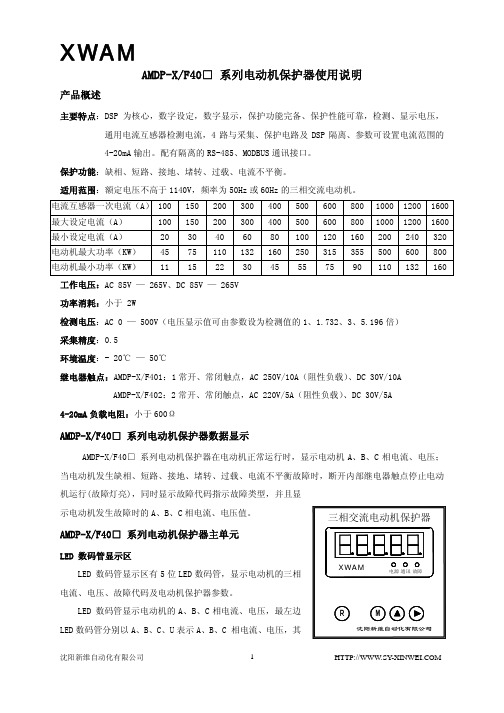
AMDP-X/F40□ 系列电动机保护器使用说明产品概述主要特点:DSP 为核心,数字设定,数字显示,保护功能完备、保护性能可靠,检测、显示电压,通用电流互感器检测电流,4路与采集、保护电路及DSP隔离、参数可设置电流范围的4-20mA输出。
配有隔离的RS-485、MODBUS通讯接口。
保护功能:缺相、短路、接地、堵转、过载、电流不平衡。
适用范围:额定电压不高于1140V,频率为50Hz或60Hz的三相交流电动机。
电流互感器一次电流(A)100 150 200300400500600800 1000 12001600最大设定电流(A) 100 150 200300400500600800 1000 12001600最小设定电流(A) 20 30 40 60 80 100120160 200 240320电动机最大功率(KW) 45 75 110132160250315355 500 600800电动机最小功率(KW) 11 15 22 30 45 55 75 90 110 132160工作电压:AC 85V — 265V、DC 85V — 265V功率消耗:小于 2W检测电压:AC 0 — 500V(电压显示值可由参数设为检测值的1、1.732、3、5.196倍)采集精度:0.5环境温度:- 20℃ — 50℃继电器触点:AMDP-X/F401:1常开、常闭触点,AC 250V/10A(阻性负载)、DC 30V/10AAMDP-X/F402:2常开、常闭触点,AC 220V/5A(阻性负载)、DC 30V/5A4-20mA负载电阻:小于600ΩAMDP-X/F40□系列电动机保护器数据显示AMDP-X/F40□ 系列电动机保护器在电动机正常运行时,显示电动机A、B、C相电流、电压;当电动机发生缺相、短路、接地、堵转、过载、电流不平衡故障时,断开内部继电器触点停止电动机运行(故障灯亮),同时显示故障代码指示故障类型,并且显示电动机发生故障时的A、B、C相电流、电压值。
FNPT与NPT与MNPT与NPTF与3_8_18NPT
FNPT与NPT与MNPT与NPTF与3/8-18NPT NPT 是National (American) Pipe Thread 的缩写,属于美国标准的60 度锥管螺纹。
NPT螺纹分:一般密封圆柱管螺纹和一般密封圆锥管螺纹二、基本尺寸:螺纹中径尺寸D2=d2=D-0.8*P螺纹小径尺寸D1=d1=D-1.6*PFNPT为内螺纹,还有个MNPT,它是外螺纹。
N.P.T为美国螺纹标准。
NPT是美标锥管螺纹National Pipe Thread的英文缩写,与国标的ZG(现在也改为NPT了)是一样的;NPTF(或者FNPT)通常指NPT的内螺纹,也就是National Pipe Thread Female;NPTM通常指NPT的外螺纹,也就是Nat ional Pipe Thread Male。
严格的说,NPTF指的是美制干密封圆锥管螺纹,牙形角60度,斜度1度47分,NP T为美制一般密封圆锥管螺纹也有通俗的说:MNPT表示阳管螺纹,FNPT表示阴管螺纹。
3/8NPT与3/8-18NPT区别3/8指的是3/8英寸(内径),也就是俗称的“三分”。
3/8:指的是3/8英寸(内径),也就是俗称的“三分”。
-18:是指每英寸螺纹牙数为18.由此也可以确定螺距为25.4/18=1.41mm。
npt3/8是60度牙形角的英制管螺纹;r3/8是55度牙形角的英制管螺纹的外螺纹。
管螺纹主要用来进行管道的连接,其内外螺纹的配合紧密,有直管与锥管两种。
公称直径是指所连接的管道直径,显然螺纹大径比公称直径大。
外螺纹是只在圆柱或者圆锥外表面的螺纹。
例如螺栓表面的螺纹即为外螺纹,而螺母的螺纹为内螺纹。
英制螺纹是螺纹尺寸用英制标注,按外形分圆柱、圆锥两种;按牙型角分55°、60°两种。
NPT一般用于管螺纹,NPT 是National (American) Pipe Thread 的缩写,属于美国标准的60度锥管螺纹,用于北美地区。
艾森F3045C型号的完整模具封闭电路保护器说明说明书

Eaton FD3045Eaton Series C complete molded case circuit breaker, F-frame, FD, Complete breaker, Fixed thermal, Fixed magnetic trip type, Three-pole, 45 A, 600 Vac, 250 Vdc, Load side, 50/60 HzGeneral specificationsEaton Series C complete molded case circuit breakerFD30457866793055463.38 in 6 in4.13 in 4.3 lb Eaton Selling Policy 25-000, one (1) year from the date of installation of the Product or eighteen (18) months from the date of shipment of the Product, whichever occurs first.UL Listed Product NameCatalog Number UPCProduct Length/Depth Product Height Product Width Product Weight WarrantyCertificationsSeries C35 kAIC at 480 Vac65 kAIC at 240 VacFFD50/60 HzComplete breakerLoad side600 Vac, 250 Vdc45 AFixed thermal, fixed magnetic Three-pole Application of Multi-Wire Terminals for Molded Case Circuit BreakersUL listed 100%-rated molded case circuit breakersApplication of Tap Rules to Molded Case Breaker TerminalsCircuit breaker motor operators product aidPlug-in adapters for molded case circuit breakers product aidMotor protection circuit breakers product aidPower metering and monitoring with Modbus RTU product aidCurrent limiting Series C molded case circuit breakers product aid MOEM MCCB Product Selection GuideStrandAble terminals product aidMulti-wire lugs product aidCounterfeit and Gray Market Awareness GuideBreaker service centersEaton's Volume 4—Circuit ProtectionMolded case circuit breakers catalogTime Current Curves for Series C® F-Frame Circuit BreakersFD3 3D Model XchangeFD3 2D Drawing XchangeF-frame Molded Case Circuit Breaker DrawingFD3 3D InventorFD3 2D PDFInstallation Instructions for EHD, EDB, EDS, ED, EDH, EDC, FDB, FD, HFD, FDC, HFDDC Circuit Breakers and Molded Case SwitchesCircuit Breakers ExplainedCircuit breakers explainedSeries C F-Frame molded case circuit breakersF-Frame 310+ Molded-case circuit breakers 15-225ASeries C J-Frame molded case circuit breakers time current curvesEaton Specification Sheet - FD3045SeriesInterrupt ratingFrameCircuit breaker type Frequency ratingCircuit breaker frame type TerminalsVoltage rating Amperage RatingTrip TypeNumber of poles Application notesBrochuresCatalogsDrawingsInstallation instructions MultimediaSpecifications and datasheetsEaton Corporation plc Eaton House30 Pembroke Road Dublin 4, Ireland © 2023 Eaton. All Rights Reserved. Eaton is a registered trademark.All other trademarks areproperty of their respectiveowners./socialmediaSeries C G-Frame molded case circuit breakers time current curves MOEM MCCB product selection guideSelling Policy 25-000 - Distribution and Control Products and Services Warranty guides。
INTORQ_BA_BFK458说明书

E型
N型
双弹力制动器
INTORQ | BA 14.0168 | 02/2016
3
产品序列号
INTORQ B
FK
-
产品组:制动器
产品族:弹簧加压式制动器
型号:458
机座号:06、08、10、12、14、16、18、20、25
结构形式: E - 可调 (可用调节环降低制动力矩) N - 不可调 L - 不可调,长寿命型
据所需的配置进行组装。标贴内容,尤其是包装标贴、型号铭牌和类型代 码,是与一套定子总成相对应的。 ❚ 以单独组件供应时,会没有上述标识。
INTORQ | BA 14.0168 | 02/2016
4
目录
1 一般说明 ........................................................................ 7 1.1 使用说明书概要 ..............................................................7 1.2 采用规范 ....................................................................7 1.3 安全须知 ....................................................................8 1.4 采用概念 ....................................................................9 1.5 采用缩写 ....................................................................9
孔轴通用密封圈型号

孔轴通用密封圈型号全文共四篇示例,供读者参考第一篇示例:孔轴通用密封圈是一种常用的机械密封元件,用于密封机械设备中的轴与孔之间的空隙,以防止液体或气体的泄漏。
密封圈形状多样,包括O型圈、X型圈、V型圈等,其中O型圈是应用最广泛的一种密封圈。
孔轴通用密封圈的选择取决于密封的工作条件、介质要求、压力要求等因素,不同的型号适用于不同的环境和工况。
孔轴通用密封圈的型号分类繁多,常见的有AS568、GB/T3452.1、JIS B2401等标准型号,也有由各个制造商自行设计的非标准型号。
AS568型号是美国标准化协会(AS)颁布的一种O型圈标准,其规格按内径、截面直径和硬度等参数进行编码。
而GB/T3452.1是中国国家标准化管理委员会颁布的O型圈标准,按相同的规格参数编码。
JISB2401是日本工业标准化联合会颁布的O型圈标准,也具有类似的编码方式。
在实际应用中,用户可以根据需求选择适合的孔轴通用密封圈型号。
要求密封性好的液压系统可以选择硬度较高的密封圈;要求耐高温的高温热油系统可以选择耐热性能好的密封圈;要求耐腐蚀的化工设备可以选择耐化学腐蚀的密封圈。
不同的工况和介质需要不同的密封圈材质和型号,以确保机械设备运行的稳定性和可靠性。
孔轴通用密封圈的安装和使用也是至关重要的。
在安装时,密封圈应保持清洁,并使用适当的工具将其安装到指定位置,避免损坏密封圈。
在使用过程中,要注意密封圈的周围是否存在任何异物或磨损,及时检查和更换密封圈,以确保其密封效果。
孔轴通用密封圈在各种机械设备中起着重要的作用,选择适合的型号和正确安装使用密封圈对延长设备寿命和降低维护成本有着重要意义。
希望本文能够对读者了解孔轴通用密封圈的类型和选择有所帮助,提高密封件的应用效率和性能。
第二篇示例:孔轴通用密封圈是一种用于密封机械设备中活塞、活塞杆、阀杆等成品的重要零部件。
密封圈的主要作用是防止液体或气体在机械设备中泄露,同时还能起到防尘、减少摩擦、保护密封面等作用。
派克汉尼汾公司 P70 工程机械用方向控制阀 样本MSG17-8546 CN 商品说明书

2派克汉尼汾公司移动液压系统欧洲分部布罗斯,瑞典工程机械用方向控制阀P70样本MSG17-8546/CN样本布局除一般信息和基本技术数据外,该样本还对P70可配置的选配功能做了描述。
我们可据此对P70进行定制配置,以便以更佳的方式控制您的机器。
阀门的每个功能区域都有一个副标题,标题后面附有简短的描述。
如果某个功能区有多个不同的位置,则会在副标题的方括号内标注位置编号,例如[P16]主溢流阀。
再接下来是一系列带有代号的选项,例如PA1、Y 以及每个代号的简短描述。
或者是一个或多个压力、流量或电压选项。
位置编号也可参见配置代号报告和备件清单。
第XX 页的一般液压原理图中展示了P70阀的基本功能区、以及代表这些功能区的条目编号。
文档和订购P70可在派克的在线产品配置器中根据客户的需求定制,定制规格通常在派克销售公司与客户协商后确定。
每个阀门配置都有唯一的ID 号、货号、详细的代码报告、3D 模型、2D 模型、备件清单和液压原理图。
阀门订购一般通过派克销售公司进行。
ID 号可在阀门产品标签上查看,并可用来识别产品,例如:新订单或维修订单。
尽早咨询,以节约时间和成本样本信息销售要约请联系您的派克销售代表,获取详细的“销售要约”。
我们的工程师经验丰富,他们对不同类型的液压系统及其工作原理都有深入的了解。
他们可以帮助您选择符合要求的阀门。
我们建议在项目规划阶段尽早咨询派克。
派克保留修改产品的权利,恕不另行通知。
本样本中使用的是典型的曲线和图表。
即使样本不断修订和更新,也不可避免存在出错的可能。
请联系派克汉尼汾,了解更多有关产品的详细信息。
3派克汉尼汾公司移动液压系统欧洲分部布罗斯,瑞典工程机械用方向控制阀P70样本MSG17-8546/CN目录目录页码一般信息 ..................................................................................................................................4开心式系统,OC (开心式阀门,P70CF )....................................................................................5控制特性 ..................................................................................................................................5恒压系统,CP ,CPU (闭心式阀门,P70CP ) ..............................................................................6控制特性 ..................................................................................................................................6负载感应系统,LS (带负载感应的阀门,P70LS ) .....................................................................7运行特性 ..................................................................................................................................7系统连接 . (7)A. 超动力连接,多阀系统,仅P70CF..................................................................................8B. 超动力连接,单阀系统,仅P70CF..................................................................................8C. 并联,多阀系统..............................................................................................................9技术数据 ................................................................................................................................10带标准入口段和端头段的阀门 .............................................................................................11液压回路图所示为基本的功能,标准阀................................................................................12液压回路图所示为基本功能(带闭式阀芯端的致动器) ......................................................13入口段 (14)[P16] 主泄压阀................................................................................................................16[P17] 压力设定................................................................................................................16[P22] 泵卸载....................................................................................................................16外泵卸载或多级主泄压功能...........................................................................................17[P25] 油箱接口T2 ............................................................................................................17[P26] 泵接口P1 ...............................................................................................................17[P27] 泵接口P2 ...............................................................................................................17[P90] 中间入口段 (18)[P93] 选项,中间入口 ......................................................................................................19[P94] 主泄压阀................................................................................................................19[P98] 压力设定................................................................................................................19端头段 (20)[P30] 端头段类型............................................................................................................20[P33] 油箱接口T1 ............................................................................................................20[P34] 油箱接口T3 ............................................................................................................20[P36] 串联功能................................................................................................................20[P37] 减压阀....................................................................................................................21[P39] 先导油过滤器 ........................................................................................................21[P40] 先导回路独立油箱接口 ........................................................................................21工作段 (22)[P47] 阀芯段类型............................................................................................................22[P51] 手柄托架................................................................................................................23[P50] 阀芯致动器 (24)带开式阀芯端的手动阀芯致动器 ............................................................................24带开式阀芯端并可手动控制的遥控阀芯致动器 .....................................................24带闭式阀芯端的遥控比例阀芯致动器.....................................................................25[P59] 电磁阀型号 .....................................................................................................26[P56] 连接器类型 .....................................................................................................26[P60] 阀芯功能................................................................................................................28[P69] 阀芯名称................................................................................................................28[P66] 压力通道................................................................................................................28阀芯选择..........................................................................................................................28[P76A ,B] 端口泄压和防气蚀阀......................................................................................29防气蚀特性......................................................................................................................29阀芯段 ....................................................................................................................................30尺寸图,标准阀门 ..................................................................................................................31尺寸图,带闭合阀芯端的型号 ...............................................................................................32尺寸图,阀芯致动器...............................................................................................................33[00]指客户规格中的项目编号。
Microchip最新选型指南

Microchip: A Partner in Your Success
Microchip is a leading provider of microcontroller and analog semiconductors, providing low-risk product development, lower total system cost and faster time to market for thousands of diverse customer applications worldwide. Offering outstanding technical support along with dependable delivery and quality, Microchip serves over 63,000 customers in more than 65 countries who are designing high-volume embedded control applications in the consumer, automotive, office-automation, communications and industrial-control markets worldwide.
32-bit PIC® Microcontrollers
The PIC32 family adds more performance and more memory while maintaining pin, peripheral and software compatibility with Microchip’s 16-bit MCU/DSC families. The PIC32 family operates at up to 80 MHz and offers ample code and data space capabilities with up to 512 KB Flash and 128 KB RAM. For more information visit: /32bit
泛塞封密封圈规格型号表

泛塞封密封圈规格型号表
(原创实用版)
目录
一、泛塞封密封圈的概念与作用
二、泛塞封密封圈的规格与型号
三、泛塞封密封圈的应用领域
四、泛塞封密封圈的选购与安装
正文
一、泛塞封密封圈的概念与作用
泛塞封密封圈是一种广泛应用于各种机械设备的密封件,其主要作用是防止工作介质的泄漏和外界杂质的进入,保证设备的正常运行和安全性。
泛塞封密封圈通常由金属骨架和密封橡胶圈组成,具有结构简单、安装方便、密封性能可靠等优点。
二、泛塞封密封圈的规格与型号
泛塞封密封圈的规格主要根据其外径、内径、宽度和金属骨架的材质等因素来表示。
常见的型号有 F4、F6、F16、F25 等,其中 F 表示泛塞封密封圈的形状,数字则表示密封圈的外径大小。
在选择泛塞封密封圈时,需要根据具体设备的要求来选用合适的规格和型号。
三、泛塞封密封圈的应用领域
泛塞封密封圈广泛应用于各种工业领域,如石油化工、冶金、电力、船舶、制药等。
在石油化工行业中,泛塞封密封圈常用于泵、阀门、管道等设备的密封;在冶金行业中,泛塞封密封圈常用于高炉、烧结炉等设备的密封;在电力行业中,泛塞封密封圈常用于汽轮机、发电机等设备的密封。
四、泛塞封密封圈的选购与安装
在选择泛塞封密封圈时,需要考虑以下几个方面:首先,要选用具有良好密封性能的密封圈;其次,要考虑密封圈的耐磨性和耐高温性能;最后,要根据具体设备的要求选择合适的规格和型号。
- 1、下载文档前请自行甄别文档内容的完整性,平台不提供额外的编辑、内容补充、找答案等附加服务。
- 2、"仅部分预览"的文档,不可在线预览部分如存在完整性等问题,可反馈申请退款(可完整预览的文档不适用该条件!)。
- 3、如文档侵犯您的权益,请联系客服反馈,我们会尽快为您处理(人工客服工作时间:9:00-18:30)。
i-PAC 10-1Xtratec® – Heptagon milling cutter F4045Table of contentF404501 02 03 04 05 06Product description Results from the market Product range Applications & Target groups Advantages and customers benefits Setting instruction2| April 2010 | VM | Spiegelhalder01 – Product description 产品描述General points 概述Wedge clamping 楔块锁紧DC = 63 – 200 mm DC = 80 – 200 mmNickelized surface 表面镀镍3| April 2010 | VM | Spiegelhalder01 – Product description 产品描述Basic body 刀体• Heptagon Face Milling Cutter, Kappa 45° 七边形面铣刀 Ø 63 (80) - 200 mm apmax = 4 / 6 mm Insert with negative basic shape 负型刀片 14 cutting edges per inserts 14 刃/片 片 Two insert sizes for complete program 2 种刀片尺寸 close pitch for cast iron machining 密齿设计, 密齿设计 适用于铸铁加工• • • • • •4| April 2010 | VM | Spiegelhalder01 – Product description 产品描述Basic body 刀体• wedge clamping of the insert 楔块锁紧– quick insert change 快速更换刀片 – stable insert 装夹稳定• Torx Plus screw– Improved Handling 操作简便 – Higher clamping / unclamping torque 锁紧/松开安全可靠• Hard nickelized surface 表面镀镍处理– Protection against wear and corrosion 抗磨损, 防腐蚀 – Improved chip removal 排屑流畅5| April 2010 | VM | Spiegelhalder01 – Product description 产品描述Insert clamping 刀片锁紧 刀片锁紧6| April 2010 | VM | Spiegelhalder01 – Product description 产品描述Insert clamping 刀片松开 刀片松开7| April 2010 | VM | Spiegelhalder01 – Product description 产品描述The insert 刀片Design DesignInsert tolerance 刀片公差Geometry Index 槽型代码negative basic shap 负型刀片8| April 2010 | VM | Spiegelhalder01 – Product description 产品描述The insert 刀片„PVD hole“• •negative basic shape 负型刀片 Heptagon basic shape with 14 cutting edges 七边形刀片, 14刃 七边形刀片 刃 designation 型号 XNHF.. Insert completely ground (Circumference) 周边磨削刀片 With corner radius 圆角刀片– XNHF070508-… XNHF090612-…• •• •With secondary cutting edge 副切削刃刀片– XNHF0705ANN- … (1,1 mm) XNHF0906ANN-… (1,4 mm)9| April 2010 | VM | Spiegelhalder01 – Product description 产品描述The insert 刀片XNHF0705ANN-D…XNHF070508-D…10| April 2010 | VM | Spiegelhalder01 –Product description产品描述Insert geometries刀片槽型•D27 The stable one稳定型–for unfavourable machining conditions适用于不理想工况–maximum cutting edge stability切削刃最稳定–high feed rates高进给–10°rake angle前角•D57 The universal one通用型–for medium machining conditions用于中等工况–universal application for most materials适用多数工件材料–10°rake angle前角•D67 The easy cutting one轻快型–for good machining conditions用于良好工况–low cutting forces切削抗力小–medium feed rates中等进给–10°rake angle前角Machining example加工案例F4045.B40.160.Z20.06Work pieces工件Periphery•Work piece工件–12,8 Liter and 14,8 Liter Diesel motor blocks12.8升和14.8升柴油机缸体•Material材料–EN-GJV-400 (GGV400)cast iron with vermiculargraphite蠕墨铸铁•Machine机床–Heller MCH 400DActual situation现状•Tool刀体–F4033.B.160.Z20.06•Insert刀片–SNGX1205ANN-F27 WKP25•Parameter参数–a p= 3-4 mm–v c= 185 m/min–f z= 0,36 mm–v f= 2650 mm/min•Tool life刀具寿命–56 Components工件•Remarks备注–Machining of the head deck– 2 passes走刀–dry干铣WALTER solution•Tool刀体–F4045.B40.160.Z20.06•Insert刀片–XNHF090616-D27 WKP25•Parameter参数–a p= 8 mm–v c= 200 m/min–f z= 0,25 mm–vf = 1990 mm/min•Tool life刀具寿命–90 components工件•Remarks备注– 1 pass走刀–Saved 84 seconds in cycle time per component每个零件节省84 秒Result 结果•Machining costs 加工成本–-44%–Saving 节省–108.891$ ≈80.726€•Tool life 刀具寿命–+ 60%–From 56 to 90 components 从56 件提高到90 件153045607590F4045F4033T o o l l i f e [p i e c e s]03 –Program range bodies刀体产品系列03 –Program range inserts刀片产品系列04 -Application areas& Target groups应用领域•For all cast materials所有铸铁材料加工•Applications应用–Face milling, roughing平面铣削, 粗加工–Mass production大批量生产–Transfer line专机线–stable machining center稳定的加工中心•Main target groups主要行业–General mechanical engineering通用机械行业–Automobile industry and its suppliers汽车行业及其零部件供应商–Energy industry能源行业04 -Application areas & Target groups 应用领域Overview grades for the machining of cast iron 铸铁加工材质综述ToughnessW e a r r e s i s t a n c e05 –Benefits for the customer客户获益•Low cutting tool costs降低刀具成本–Due to fourteen cutting edges per insert由于每个刀片有14 刃•High chip removal volume提高材料去除率–even on low-powered machines即使在低功率机床上–Low power consumption due to the high-positive geometry大前角槽型降低功率消耗–high feed rate due to close pitch version密齿设计提高进给•High process reliability提高工艺可靠性–Due to stable indexable inserts (negative basic shape)负型刀片, 加工稳定–large support of insert on the body刀体上的刀片支撑面大Xtra tec Heptagon milling cutter F4045 Setting instruction安装指南06 –Setting instruction F4045安装指南•Required parts要求部件:–Torx screwdriver Torx 螺丝刀–Spanner扳手–Inserts刀片–F4045 milling cutter, including thescrews and wedges刀体, 包括螺钉和楔块Bonding agent (not fat) 06 –Setting instruction F4045安装指南•Step 1:–Slide the wedge, as shown in the picture on the screwdriver. Place the sum screw on the tip of the screwdriver.先将楔块放入扳手, 并将放上螺钉, 注意方向.•Step 2:–Screw the wedge and the sum screw in the thread. Use the spanner to hold the wedge in position.将楔块和螺钉旋入刀体, 用固定扳手将楔块定位–XNHF0705.. : SW8–XNHF0906.. : SW1006 –Setting instruction F4045安装指南•Step 3:–Once the wedge is screwed in farenough to place him like shown in thepicture on the right.确保楔块旋入足够长度, 将其按照右图所示放置.•Step 4:–Now you can insert the insert into yourset position. Hold the insert firmly whiletightening the sum screw. The wedge ismoving in the right position as soon asyou start to bolt and clamps the insertin the correct position.现在可以将刀片放入刀片槽. 推紧刀片, 旋入螺钉. 当你开始在正确位置锁紧刀片的时候,楔块也将自动旋转到正确的位置.06 –Competitors竞争对手ISCAR F45WG/NM•Kappa 44,3°•two different pitches•one insert size•Octagon negative•16 cutting edges •designation ON.U080608..•Ic= 20,2 mm•ap = 5,5 mm06 –Competitors竞争对手Coromant CoroMill365•Kappa 65°(30°)•two different pitches•one insert size•square negative•8 cutting edges•designation R365-1505ZNE..•Ic= 15 mm•ap = 4,5 (6,1) mm06 –Competitors竞争对手Kennametal Hexacut •Kappa 45°(60°)•one pitch•one insert size•Hexagon negative•12 cutting edges •designation HN.X0905…•Ic= 15,88 mm•ap = 6,5 (8) mm •secondary c. e. 1,3 mm06 –Competitors竞争对手Kennametal Dodeka•Kappa 45°•one pitch•one insert size•hexagon negative•12 cutting edges •designation HNGJ0905AN…•Ic= 15,88 mm•ap = 4,5 mm•secondary c.e. 1,8 mm06 – Competitors 竞争对手 Mitsubishi AHX• • • • • • • • • Kappa 40° two pitches one insert size Heptagon negative 14 cutting edges designation NNMU200608.. Ic = 20 mm ap = 6 mm secondary c.e. 1 mm31| April 2010 | VM | Spiegelhalder07 - Typical work pieces 典型零件Cylinderhead 缸盖Rotor hub 轮毂Manifolt 排气管Engin block 缸体32| April 2010 | VM | Spiegelhalder07 - Typical work pieces 典型零件Differential case 箱体Differential case 箱体Inlet 进气管33| April 2010 | VM | SpiegelhalderThank you.。