JR8624B-V2.0DATASHEET
SGM8624中文资料

Sensors Audio Active Filters A/D Converters Communications Test Equipment Cellular and Cordless Phones Laptops and PDAs Photodiode Amplification Battery-Powered Instrumentation
The SGM8621/2/3/4 are designed to provide optimal performance in low voltage and low noise systems. They provide rail-to-rail output swing into heavy loads. The input common-mode voltage range includes ground, and the maximum input offset voltage is 3mV for SGM8621/2/3/4. They are specified over the extended industrial temperature range (−40°C to +125°C). The operating range is from 2.5V to 5.5V.
f = 1kHz f = 1kHz
Specifications subject to change without notice.
TYP
+25℃
0.7 1 1 -0.1 to +5.6 90 92 100 110 2.7
0.1 0.015
48 2.6
6.2 1.4
94 250
Foxboro 电浮筒液位计

Product Specifications12.2012PSS EML0710G-(en) 244LD Levelstar Intelligent Buoyancy Transmitter forLiquid Level,Interface and Densitywith Torque tube–HART-Version–The intelligent transmitter244LD LevelStar is designed to perform continuous measurements for liquid level,interfa-ce or density of liquids in the process of all industrial applications.The measurement is based on the proven Archime-des buoyancy principle and thus extremely robust and durable.Measuring values can be transferred analog and digi-tal.Digital communication facilitates complete operation and configuration via PC or control system.Despite extre-me temperatures,high process pressure and corrosive liquids,the244LD measures with consistent reliability and high precision.It is approved for installations in contact with explosive atmospheres.The244LD LevelStar combines the abundant experience of FOXBORO ECKARDT with most advanced digital technology.FEATURES•HART Communication,4to20mA •Configuration via FDT-DTM•Multilingual full text graphic LCD•IR communication as a standard•Easy adaptation to the measuring pointwithout calibration at the workshop•Linear or customized characteristic•32point linearisation for volumetric measurement •Backdocumentation of measuring point•Continuous self-diagnostics,Status and diagnostic messages•Configurable safety value•Local display in%,mA or physical units•Process temperature from–196°C to+500°C•Materials for use with aggressive media•Micro sintermetal sensortechnology2244LDPSS EML0710G-(en)PACTware:OperationFDT-DTM:ConfigurationSupply via power supply unit with communication;ExDirect supply with communication;not ExFurter supply circuits see Master Instruction document.PSS EML0710G-(en)244LD3TECHNICAL DATAData refer to the sensor material Type316L(1.4404) Explosion protection certificates must be observed! Input/OutputMeasuring ranges........50mm to50mupper and lower range valuecontinuously adjustable Standard lenghts ofDisplacer(204DE)........350..3000mm,14..120in;further lenghts on request Weight of displacer1)......max.25NMeasuring span..........2...20N contin.adjustable(to1N on request)Span ratioTurn-down..............1:1..1:10(1:20on request) Accuracy2).............±0.2%;increased accuracywith customized adjustment Transfer function.........linear or customized with upto32setpoints Configuration-with FDT-DTM per HART protocol-via2-wire connection4..20mA-via IR communication-with multi-lingual,full graphic LCD display with%,mA, physical units and2from the outside-to-use buttons Load.................R Bmax=(U S–12V)/23mACommunication HART Connection.............Two-wire systemSupply voltage U S3).......>12V+Rb*0.025ARb is the total burden resistor for lines,HART measure-ment resistor and communication.Current sink.............max.24mASignal range............4to20mAOperating range..........3.8to20.5mA(acc.NE43)Critical error alarms in the2-wire Communication..........<3.6mA and>21mA HART Protocol-2-wire................1200Baud,HART compliant -IR communication.......19200Baud Communication Hardware-Handterminal..........HT375/475-PC Software...........WINxx and FDT/DTM1)For measurement of interface or density:weight25N+buoyant force at lowest density2)Accuracy acc.ANSI/ISA-S51.1-19793)Us(max)with explosionproof device<30V,otherwise<42V Operating conditions4)Process temperature......–196°C...+500°C Pressure ratingacc.to DIN............PN16,40,63,100,160,250 acc.to ANSI...........Class150,300,600,900,1500 Ambient temperature5)6)...–40°C...+70°C7) Relative humidity.........up to100% Condensation...........permittedTransportation-storage temperature.......–40°C...+85°C Protection..............IP66(acc.DIN40050) The device can be operated at a class D2location in accordance with DIN IEC654,part1.Operation condition effectsAmbient temperature......–10°C...+70°CZero................<0.1%/10K8)Span...............<0.07%/10KTotal(0.1max.sp.0.07measured value±)%/10K (sp.=measuring span)<-10°C/>+70°C......twice the valueProcess temperature......<0.1%/10K8) Operating pressure.......no influence(vakuum resis-tant)Transitional behaviorDynamic behaviorDamping(90%-time).....0...32sSwitch-on time.........7sStep response(63%-time)with damping0s........250msUpdate rate.............10/sLong term stability........<0.2%/6months at20°C8) Noise suppressionCommon mode voltage...<AC250V effCommon mode rejection..120dBSeries mode rejection....50dB Filter.................Smart Smoothing4)Not with all materials–see Table of Comparison of Materials page65)Ambient temperature must not exceed50°C at measuring modulehousing,when process medium or heating of medium exceed300°C6)–50°C on request7)Display not readable at T<–20°C or T>+70°C8)For max.measuring span4244LD PSS EML0710G-(en)Material,Pressure Rating&Contact Face,Mounting Directionsee Model CodesMaterial Amplifier housing..Aluminum(Alloy No.GD-Al Si12),Polyurethan coatedor Stainless SteelFor Sour Gas applications acc.to NACE Standard MR-0175-95: Wafer body............316L(1.4404)Torque tube...........Hastelloy C or Inconel600 The material of the seal at the Torque tube bearing corre-sponds to the material of the head piece.MountingMounting method.........sandwich mountedacc.to DIN............DN80,DN100acc.to ANSI...........3inch,4inchNote:Always follow the RH or LH version!See the picture below.The device can not be used“upside down”.All inter-nal parts are mounted and calibrated in inverse manner. The conversion can be performed only by the manufacturer or a contractual partner.Otherwise calibration and pressure test are invalid.Weight Transmitter.............see table page7 Displacer...............see table page10Electrical connectionCable entry thread........M20x1.5or1/2-14NPT Cable gland and screwed sealing plug have to be ordered separately under model code BUSG...For equipment in Ex d version,1screwed sealing plug made of stainless steel is included in delivery.Screw terminals..........wire cross-section up to2.5mm²Test sockets............Ø2mm Electromagnetic compatibility EMCOperating conditions......industrial environment Immunity according toEN61326(3/2002)......fulfilledEmission according toEN61326(3/2002)......fulfilledEN55011,May2000,Group1,Class A........fulfilledEN50081-2............fulfilledNAMUR recommendation Ne21Status Aug.1998fulfilled SAFETY REQUIREMENTSCE LabelElectromagnetic compatibility............2004/108/EC fulfilled Explosion protection acc.to ATEX...94/9/ECSafetyAccording to EN61010-1(resp.IEC1010-1)........safety class IIIInternal fuses............none(or not replaceable bycustomer)External fuses...........Limitation of power supplies for fire protection have to be observed due to EN61010-1, appendix F(rsp.IEC1010-1)PSS EML0710G-(en)244LD5Electrical classification ATEX 2)3)intrinsic safe:AID 421II 1/2G EEx d ib/ia IIC/IIB T4/T6PTB 04ATEX 2011X Zone 0AID 421II 2G EEx d ib/ia IIC/IIB T4/T6PTB 04ATEX 2011X Zone 1explosion-proof:AD 432II 1/2G Ex da/db IIB/IIC T4/T6PTB 02ATEX 1025X Zone 0AD 432II 2G Ex da/db IIB/IIC T4/T6PTB 02ATEX 1025XZone 1Zone 2:Manufacturer’s DeclarationFurther certificates see also our website:http://www.foxboro-eckardt.eu/Ex_de_en/allEX_244LD_en_de.html -FM -CSA -NEPSI -Russia-Kasachstan-Approvals for use on sea ships2)With appropriate 3)National6244LD PSS EML0710G-(en) Comparison of MaterialService Limits of wafer body PN250made of(material)Max.operating pressure in bar at temperature in°CTable of Weights1)Values on requestPSS EML0710G-(en)244LD78244LD PSS EML0710G-(en)(continued)PSS EML0710G-(en)244LD9(continued)10244LD PSS EML0710G-(en) Displacer204DETypical Dimensions and Weights for Density RangesΔρ1)1)Δρ=ρ1-ρ2ρ1=density of lower mediumρ2=density of upper medium2)Using displacer material1.4571can cause small devia-tions in diameter,volume and weight.3)For measurement of interface or density,the max.den-sity of the lower medium is1350kg/m³.4)Min.density of the lower mediumIf a Displacer Chamber is used,the difference bet-ween the diameter of the Displacer and the inside diameter of the Displacer Chamber must be at least 10mm.Lengths<350mm and>3000mm,and density ran-ges<100kg/m³and>2000kg/m³on request.AccessoriesFor Displacer Chamber204DC,Flange combination 204FK and Cover Flange Kit204BCF see PSS EML0901,204..Accessories for Buoyancy Transmitter.(continued)Table of versions for dimensions c,d,g see drawing on next pageVersion Form of Sealings DN80/3inch DN100/4inch PN c d g c d gDIN EN 16B1DIN EN1092B2/C/D/F/EDIN EN109214082140160102162 4063100Form L DIN2696160250ANSI 150RF/SG/STANSI B16.514082140160102162 3006009001500150RJFANSI B16.514082140160102174 3001476009001500102162206 300LF/LM/LG/LTANSI B16.514082140160102174 6009001500RF Raised Face RJF Ring Joint Face LF Large Female LM Large Male LG Large Groove LT Large Tongue SG Small Groove ST Small TongueDIMENSIONS244LD up to PN250/Class1500Subject to alterations -reprinting,copying and translation prohibited.Products and publications are normally quo-ted here without reference to existing patents,registered utility models or trademarks.The lack of any such refe-rence does not justify the assumption that a product or symbol is free.FOXBORO ECKARDT GmbH Pragstr.82D-70376Stuttgart Tel.+49(0)711502-0Fax +49(0)711502-597Mail to:salessupport@foxboro-eckardt.de http://www.foxboro-eckardt.euDOKT 556588038~1Product Specifications for Intelligent Transmitters Product Specification:Device:PSS EML0610144LD Intelligent Buoyancy Transmitter for Liquid Level,Interface and Density with Displacer and Torque TubePSS EML0710A 244LD Intelligent Buoyancy Transmitter for Liquid Level,Interface and Density PSS EML0710G with Displacer and Torque Tube (A:TransStar G:LevelStar )PSS EML1610144LVD Intelligent Buoyancy Transmitter for Liquid Level,Interface and Density with DisplacerPSS EML1710244LVP Intelligent Buoyancy Transmitter for Liquid Level,Interface and Density with DisplacerPSS EML0901204xxAccessories for Buoyancy Transmitters PSS EMO0100Accessories for Devices with HART-Protocol。
模块型温度控制器说明书

模块型温度控制器本说明书对温控器设置、配线及各部分名称等进行说明,使用本产品前,请认真阅读本说明书,在理解内容的基础上正确使用。
并请妥善保存,以便需要时参考。
⊙多种输入信号类型可选⊙具有测量显示、控制输出、报警输出、变送输出、RS485通信等功能⊙多种PID 控制算法可供选择,且具有自整定功能⊙本产品使用于工业机械、机床、普通测量仪器及设备中⊙经济实用,操作简便特点一、安全使用注意周围环境条件存贮环境1、电气参数表:室内使用,温度:0~50℃ 无结露,湿度:<85%RH,海拔小于2000m -10~60℃,无结露采样速度2次每秒供电电源整机功耗继电器容量AC 250V /3A 额定负载寿命大于10万次AC/DC 100~240V (85-265V)< 6VA四、主要技术参数三、常规型号说明二、设备型号通信接口 电流输出固态继电器输出绝缘电阻静电放电脉冲群抗扰度浪涌抗扰度电压暂降及短时中断抗扰度隔离耐压DC 24V 脉冲电平,带载<30mADC 4~20mA 带载小于500Ω,温漂250PPM RS485接口 Modbus-RTU 协议,最多接入30台输入、输出、电源对机壳>20MΩIEC/EN61000-4-2 Contact ±4KV /Air ±8KV perf.CriGTEria B IEC/EN61000-4-4 ±2KV perf.CriGTEria B IEC/EN61000-4-5 ±2KV perf.CriGTEria BIEC/EN61000-4-29 0%~70% perf.CriGTEria B信号输入与输出及电源1500VAC 1min,60V 以下低压电路之间DC500V,1min 整机重量约 400g机壳材质面板材质停电数据保护安全标准PA66-FR(难燃度UL94V-0)PVC 胶片与PEM 硅胶按键10年,可写数据次数100万次IEC61010-1 过电压分类Ⅱ,污染等级2,等级Ⅱ(加强绝缘)2、测量信号参数表:3、隔离模式框图:*选型时请注明要求412365781)本产品不得使用在原子能设备以及与人命相关的医疗器械等方面。
MP2122_datasheet

EClamp2122SUSB Downstream Port Filter & TVSFor EMI Filtering and ESD Protection® JEDEC SOT-23 6L packagePb-Free, Halogen Free, RoHS/WEEE Compliant Nominal Dimensions: 2.9 x 2.8mmMolding compound flammability rating: UL 94V-0 Marking: Marking Code + Date Code Packaging: Tape and ReelThe EClamp ®2122S is combination EMI filter and line termination device with integrated TVS diodes for use on USB 2.0 interfaces. This device utilizes solid-state silicon-avalanche technology for superior clamping performance and DC electrical characteristics. Theyhave been optimized for protection of USB inter-protection of USB inter-faces faces in cellular phones and other portable electron-ics.USB line termination is achieved with a series 22Ωresistor on both the D+ and D- USB lines. Theseresistors preserve signal integrity by matching the cable impedance to that of the differential driver. The 15k Ωpull-down resistors complete the termination circuit on each line. They are required by the USB specification to identify the line as a downstream connection. The capacitors are used to bypass high frequency energy to ground and for edge rate control of the USB signals.Integrated TVS diodes provide ESD protection of both (D+ & D-) data lines and the voltage bus (V BUS ). The TVS diodes provide effective suppression of ESD voltages in excess of 25kV (air discharge) and 20kV (contact discharge) per IEC 61000-4-2.The EClamp2122S is in a 6-pin SOT-23 package. The leads are finished with lead-free matte tin. It is suit-able for use in USB hubs, computers, peripherals, and portable devicesUSB 1.1 Interfaces USB Hubs Printers MonitorsServers, Desktop, and Notebook computersEMI/RFI filtering and line termination with inte-grated ESD protectionESD protection for USB power (V BUS ) and data lines (D+ & D-) to IIEC 61000-4-2 (ESD), ±25kV (air),±20kV (contact)Filtering and termination for two USB data lines Series resistors for impedance matchingIntegrated pull down resistors as required by the USB specification for downstream ports Low TVS operating voltage (5.25V) Solid-state technologyAbsolute Maximum Ratinggn i t a R l o b m y S e u l a V s t i n U re w o P e t a t S -y d a e t S P S S 001W m 2-4-00016C E I r e p e g r a h c s i D r i A D S E 2-4-00016C E I r e p e g r a h c s i D t c a t n o C D S E V D S E 5202V k e r u t a r e p m e T g n i t a r e p O T J 58+o t 04-C °er u t a r e p m e T e g a r o t S T GT S 051+o t 55-C°re t e m a r a P l o b m y S s n o i t i d n o C m u m i n i M l a c i p y T m u m i x a M s t i n U e g a t l o Vf f O -d n a t S e s r e v e R S V T V M W R 52.5V e g a t l o V n w o d k a e r B e s r e v e R S V T V R B I t A m 1=6Ve c n a t s i s e R s e i r e S R S e n i L h c a E 022242Ωe c n a t s i s e R n w o d l l u P R D P e n i L h c a E 5.31515.61k Ωe c n a t i c a p a C e d o i D S V T C e n i L h c a E V R z H M 1=f ,V 0=720333F p ec n a t i c a p a C l a t o T C TO T tu p t u O r o t u p n I n e e w t e B d n u o r G o t V R zH M 1=f ,V 0=05Fp o C)Typical CharacteristicsESD Clamping (Pin 4 or 5 to GND)(8kV Contact per IEC 61000-4-2)ESD Clamping (Pin 4 or 5 to GND)(-8kV Contact per IEC 61000-4-2)Note: ESD data is taken with a 20dB attenuator ESD Clamping (Pin 1 to GND)(-8kV Contact per IEC 61000-4-2)ESD Clamping (Pin 1 to GND)(8kV Contact per IEC 61000-4-2)Typical Insertion Loss S21(Pin 2 to 5 with respect to GND)Typical Insertion Loss S21(Pin 3 to 4 with respect to GND)Normalized Junction Capacitancevs. Reverse Voltage (Data Pins)0.00.10.20.30.40.50.60.70.80.91.01.11.21.31.41.5012345Reverse Voltage - V R (V)C J (V R ) / C J (V R =0)Applications InformationFigure 1 - EClam Figure 1 - EClamp2p2p2122S Cir 122S Cir 122S Circuit Diagramcuit DiagramDevice ConnectionThe EClamp2122S is designed to provide termination,EMI filtering and ESD protection for two USB I/O lines.The equivalent circuit diagram is shown in Figure 1.The device is connected as follows:zUSB data lines are routed through theEClamp2122S for easy implementation and opti-mum pc board layout. Pin 1 is connected to the voltage supply line. The input of the D+ line isrouted into pin 2 and out of pin 5. The input of the D- line is connected at pin 3 and the output at pin 4. Pin 6 is connected to ground. The ground connection should be made directly to the ground plane for best results. The path length is kept as short as possible to reduce the effects of parasitic inductance in the board traces.USB Port Design with EClamp2122SThe Universal Serial Bus (USB) specification requires termination and filtering components for proper opera-tion. In addition, an open USB socket is vulnerable to hazardous ESD discharges in excess of 15kV. These discharges can occur on the data lines or the voltage bus. The EClamp2122S is an easily implemented solution designed to meet the termination & EMI filter requirements of the USB specification revision 1.1. It also provides ESD protection to IEC B line termination is achieved with series resistors on both the D+ and D- lines. These resistors preserve signal integrity by matching the cable impedance to that of the differential driver. 15k Ω pull-down resis-tors are used to identify a downstream port. Capaci-tors are used to bypass high frequency energy to ground and for edge rate control of the USB signals.Integrated TVS diodes provide ESD protection of both (D+ & D-) data lines and the voltage bus (V BUS ).General layout guidelines are given below:z Avoid running D+ & D- signal line traces near high speed clock lines or similar signal lines.z Avoid running critical signal lines near board edges.z Place the EClamp2122S near the USB connector to restrict transient coupling.zMinimize the path length between the USB connec-tor and the EClamp2122S.Outline Drawing - SOT-23 6LContact InformationSemtech CorporationProtection Products Division200 Flynn Rd., Camarillo, CA 93012Phone: (805)498-2111 FAX (805)498-3804Tape and Reel SpecificationDevice Orientation in Tapee p a Th t d i W)x aM(,B D1D E FK)X AM(P0P2P)X AM(T W mm8mm2.4)561.(mm1.0+5.1mm0.0-mm0.150.0±01.±57.1mm50.0±5.3mmmm4.21.0±0.4mm1.0±0.4mm50.0±0.2mmmm4.0mm0.8mm3.0+mm1.0-0A0B0Kmm50.0-/+32.3mm50.0-/+71.3mm50.0-/+73.1User Direction of feedYW = 2 - Alphanumeric characters for Date Code。
FT245BL-REEL,FT245BL-REEL, 规格书,Datasheet 资料
VIRTUAL COM PORT (VCP) DRIVERS for Windows 98 and Windows 98 SE Windows 2000 / ME / Server 2003 / XP Windows XP 64 Bit Windows XP Embedded Windows CE 4.2 MAC OS-8 and OS-9 MAC OS-X Linux 2.40 and greater Windows 98 and Windows 98 SE Windows 2000 / ME / Server 2003 / XP Windows XP 64 Bit Windows XP Embedded Windows CE 4.2 Linux 2.4 and Greater Easy MCU / PLD / FPGA interface to USB Upgrading Legacy Peripheral Designs to USB USB Instrumentation USB Industrial Control USB Audio and Low Bandwidth Video data transfer PDA USB data transfer USB MP3 Player Interface USB FLASH Card Reader / Writers Set Top Box (S.T.B.) PC - USB interface USB Digital Camera Interface USB Hardware Modems USB Wireless Modems
D2XX (USB Direct Drivers + DLL S/W Interface)
APPLICATION AREAS
日本富士FUJI信号隔离器PWB介绍
1
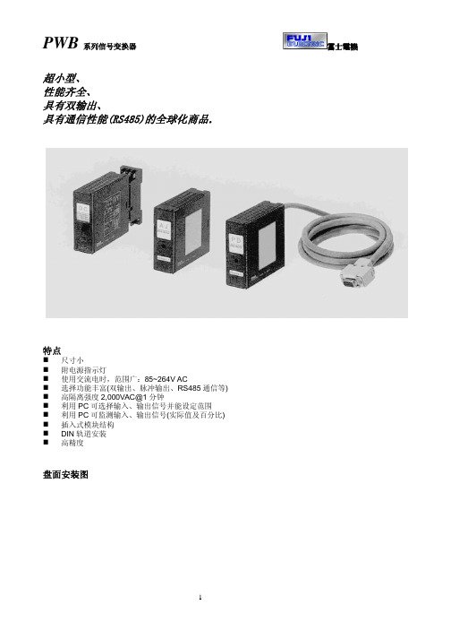
PWB 系列信号变换器
类型一览表
类型
1
直流变换器
2
直流变换器(高速型)
3
交流变换器(1 输出)
4
交流变换器(可带双输出)
5
测速发电机变换器
6
热电偶变换器
7
热电阻变换器
8
电位计变换器
9
慢速频率变换器
10
信号分配器
11
反向变换器
12
直流报警器
13
简易设定器
14
智能设定器
బɻཥዚ
型号
输入
PWBDC 1~5V、0~10V、0~5V PWBHS 0~20MA、4~20MA
PWBDY 4~20MA(DC24~28V)
PWBRV
PWBAS PWBAJ PWBPD
1~5V、0~10V、 0~5VDC 4~20MA
第一输出
1~5V 0~5V 0~10V 0~20MA 4~20MA
5~1V 5~0V 10~0V 20~0MA 20~4MA 继电器
第二输出
1~5V 4~20MA RS485
页数 3 4 5 6 7
8
注: 9
PWBHS
PWBAC 10
PWBTG 11
PWBAS
除外
12
ቤተ መጻሕፍቲ ባይዱ
13
14 15 16
通用技术规格
绝缘电阻 绝缘强度
辅助电源
项目
输入、输出、电源、接地之间 第一输出、第二输出之间 交流 直流
消耗功率、消耗电流
使用温度、湿度范围 零点调整范围 量程调整范围 外形尺寸 重量
技术规格
2
PWBAC PWBAU
上海精浦绝对式编码器选型
EAS124(24bit 超高分辨率,大孔径)
单圈24位超高分辨率、高精度、大孔径绝对值编码器EAS124
* 德国原装高精度刻线光学系统。
* 绝对值光电码盘,无需电池,抗干扰强 。
* 单圈 24 位超高分辨率,每圈 16777216 分割度。
* RS485 高速通迅。
允许转速: 输出刷新周期: 连接电缆: 外形特征: 信号调整:
2400 转/分 <1ms 1 米屏蔽电缆径向侧出(其余形式可订货) 金属外壳,密封双轴承结构(见外形尺寸附图 P16) 可 4mA 输出微调,20 mA 输出微调;可方向设置;可预设位 置,外部置位,例如外部置零
输出接口:(以产品说明书为准)
* 绝对值数字码盘,内置信号转换,4-20mA 模拟电流与 RS485 输出,方便连接各
种设备。
* EasyPro 软件设定,多用途、多功能,直接对应单圈角度、转动平移速度测量。
* 4mA 对应值、20mA 对应值任意设定及微调;方向设定;外部置位线设定预设
位置,安装方便,无需找零。
* 内部绝对值码盘,全数字化计值,信号无温度、机械影响,信号干扰零点飘移
测角度 测长度 测速度的多面手
* 内部绝对值码盘,全数字化计值。
* RS485 自由协议输出,或 Modbus RTU 输出。
* EasyPro 软件设定,多用途、多功能,直接对应单圈角度、转动平移速度测量。
* 多地址设定;通讯波特率设定,分辨率、方向设定。
* 外部置位线设定预设位置,安装方便,无需找零。
单圈 24 位超高分辨率、高精度绝对值编码器 EAS424
* 德国原装高精度刻线光学系统。
* 绝对值光电码盘,无需电池,抗干扰强 。
JR223B DATASHEET V2.0A
w 系统更稳定可靠;
6、 超小封装,节省更多的板材空间;
w 三、产品应用 w触摸电视机、触摸冰箱、触摸洗衣机、
触摸电梯控制器、触摸医疗仪器、触摸 安防产品、触摸传真机、触摸打印机、 触摸彩票机、触摸消毒柜等。
4
KV
w参数 w 工作电压
符号 VDD
测试条件
最小值 典型值 最大值 单 位
2.0
3.0
5.5
V
工作电流
IOP
VDD=3.0V
--
3.5
7.0
uA
输入端
VOL
输入低电压
0
--
0.2 VDD
输入端
VOH
输入高电压
0.8
--
1.0 VDD
输出响应时间 TR
VDD=3.0
--
--
60
ms
传感器
FSEN VDD=3.0 无负载 --
--
1
Mhz
Rev. 2.0A
深圳市福田区新闻路景苑大厦 A 座 602 室
2
深圳市劲锐科技有限公司
SHENZHEN JINRUI TECHNOLOGIES CO., LTD.
TEL:0755-83088967 83088481
FAX:0755-83088481
1
输出功能
LEVEL Hold 模式,高电平有效 CMOS 输出
LEVEL Hold 模式,低电平有效 CMOS 输出
触摸空调、触摸电风扇、触摸电话机、 触摸空气清新机、触摸吸尘器、触摸跑
- 1、下载文档前请自行甄别文档内容的完整性,平台不提供额外的编辑、内容补充、找答案等附加服务。
- 2、"仅部分预览"的文档,不可在线预览部分如存在完整性等问题,可反馈申请退款(可完整预览的文档不适用该条件!)。
- 3、如文档侵犯您的权益,请联系客服反馈,我们会尽快为您处理(人工客服工作时间:9:00-18:30)。
0
最长输出时间 16 秒
1
无穷大 (默认状态)
首次触摸时其响应速度会慢些,此后其响应 速度将和快速模式一样,因此时系统已经自 动转换到快速模式下进行工作。当所有键释
快速反应模式与低功耗模式选择(由 SGM 决定)
JR8624有提供快速反应和低功耗两种模式可
m 选择,由SGM端口进行选择,当SGM端口连接到
六、 电气参数
参数
深圳市劲锐科技有限公司
SHENZHEN JINRUI TECHNOLOGIES CO., LTD.
TEL:0755-83088967 83088481
FAX:0755-83088481
Mail: info@ 技术支持:13728621792
符号
条件
值
SMK
功能说明
1 同一时间允许多个按键响应(默认状态)
0
同一时间只允许 1 个按键响应
Rev. 2.0A
深圳市福田区新闻路景苑大厦 A 座 602 室
2
深圳市劲锐科技有限公司
SHENZHEN JINRUI TECHNOLOGIES CO., LTD.
TEL:0755-83088967 83088481
单位
ቤተ መጻሕፍቲ ባይዱ
工作温度
TOP
---
-40 ~ +85
℃
存放温度
TSTG
---
-50 ~ +125
℃
电源电压 输入电压
m 芯片抗靜電强度 HBM
VDD VIN ESD
Ta=25°C Ta=25°C
---
VSS-0.3 ~ VSS+6.0
V
VSS-0.3 ~ VDD+0.3
V
5
KV
o 参 数 .c 工作电压
工作电压
h 内部稳压器输出 工作电流 c 输入端 输入端
te 输出口灌电流 i- 输出口拉电流
按键响应时间
符号 VDD VDD R_V IOP VIL VIH IOL IOH
TR
测试条件 禁用内部稳压器 启用内部稳压器
VDD=3.0V 输入低电压 输入高电压 VDD=3.0V, VOL=0.6V VDD=3.0V, VOL=2.4V
可以用来设定开漏输出。
.jin STG SCD ALH
OUT1-OUT4 输出说明
010
LEVEL HOLD 模式,CMOS 输出,高电平有效
011
LEVEL HOLD 模式,CMOS 输出,低电平有效
000
LEVEL HOLD 模式,开漏输出,高电平有效
w 0 0 1
LEVEL HOLD 模式,开漏输出,低电平有效
i- 输出模式控制(由 ALH、STG、SCD 选择控制):
u JR8624 在 LEVEL HOLD 模式下其输出端口(OUT4-OUT1)可由 ALH 引脚来设定输出是高电平有效还
r 是低电平有效。同时也可由 STG 引脚来设定是 LEVEL HOLD 模式还是 ON/OFF 控制模式。SCD 引脚
深圳市劲锐科技有限公司
SHENZHEN JINRUI TECHNOLOGIES CO., LTD.
TEL:0755-83088967 83088481
FAX:0755-83088481
Mail: info@ 技术支持:13728621792
一、概述
4 键电容式触摸按键 IC------JR8624B
VDD 时JR8624工作在快速模式下,当SGM端口
o 五、应用电路图
放超过8 秒后,系统又将恢复到低功耗工作
模式。
SGM
功能说明
1
快速反应模式
0 低功耗模式(默认)
ww.jinrui-tech.c 注意事项: w1、 尽量保证感应焊盘到 IC 之间的连线短、细为原则,不能交叉或是平行走线;
2、 电源需稳定,否则会影响基准不稳,造成灵敏度变化;
件,不会磨损,其感测部分可以放置到
o 任何绝缘层(通常为玻璃或塑料材料)
的后面,很容易制成与周围环境相密封
.c 的键盘。面板图案随心所欲,按键大小、
形状自由选择,字符、商标、透视窗等 可任意搭配,外形美观、时尚,而且不
h 褪色、不变形、经久耐用。从根本上改 c 变了各种金属面板以及机械面板无法
达到的效果。其可靠性和美观设计随意
类型说明
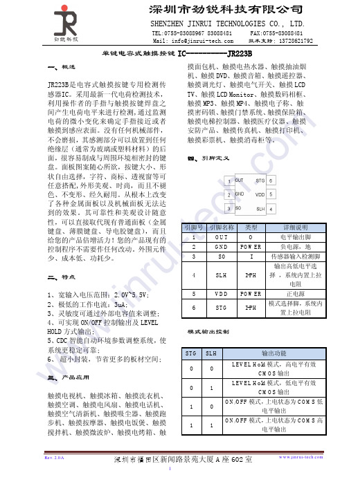
I
传感器输入
功能
5
ALH
I-PL
输出高低电平选择,
6
VDD
POWER
正电源电压
7
m 8 o 9 .c 10 h 11 c 12 te 16-13
STG SGM KTM1 GND SCD SMK OUT4-OUT1
I-PL I-PL I-PH POWER I-PH I-PH
O
输出类型选择: 低功耗模式与快速反应模式选择 按键最长有效时间输出选择 负电源,地 开漏输出选择 同一时间单键有效&多键有效选择 直接输出端口
VDD=3.0
最小值 2.0 2.4 2.2 -0 0.8 --100
典型值 3.0 -2.3 2.5 --8 -4 --
www.jinru 七、封装(SSOP16)
最大值 5.5 5.5 2.4 -0.2 1.0 --200
单位 V V V uA
VDD VDD mA mA mS
Rev. 2.0A
深圳市福田区新闻路景苑大厦 A 座 602 室
4
FAX:0755-83088481
Mail: info@ 技术支持:13728621792
悬空或接GND时,JR8624工作在低功耗模式。
按键最长有效时间选择(由 KTM1 决定)
在快速模式下,其响应速度较快,但是耗电流
KTM1
功能说明
会稍大.在低功耗模式下,功耗会较小,但是
w 低功耗模式:2.5uA;
快速反应模式:9uA;
w 3、 每个触摸通道均可通过外部补偿电 容来调节灵敏度(0~50pF);
w4、 提供更多的输出方式:LEVEL HOLD
触摸空气清新机、触摸吸尘器、触摸跑 步机、触摸按摩器、触摸电饭煲、触摸 搅拌机、触摸微波炉、触摸电烤箱、触 摸面包机、触摸电热水器、触摸抽油烟 机、触摸 DVD、触摸音箱、触摸遥控 器、触摸调光灯、触摸台灯、触摸电气 开关、触摸机箱、触摸笔记本多媒体键、 触摸数码相机、触摸 GPS、触摸 iPOD 音箱、触摸手机、触摸手电筒、触摸 LCD TV、触摸 LCD Monitor、触摸数码相框、 触摸 MP3、触摸 MP4、触摸电子称、 触摸密码锁、触摸门禁系统、触摸保险 箱、触摸电梯控制器、触摸医疗仪器、 触摸安防产品、触摸传真机、触摸打印 机、触摸彩票机、触摸消毒柜等。
三、产品应用
JR8624B 是 4 键 电 容 式 触 摸 按 键 专 用 检
触摸电视机、触摸冰箱、触摸洗衣机、
测传感器IC。采用最新一代电荷检测技
触摸空调、触摸电风扇、触摸电话机、
术,利用操作者的手指与触摸按键焊盘 之间产生电荷电平来进行检测,通过监 测电荷的微小变化来确定手指接近或
m 者触摸到感应表面。没有任何机械部
te 性,可以直接取代现有普通面板(金属
键盘、薄膜键盘、导电胶键盘),而且
i- 给您的产品倍增活力!可实现直接模
式、扫描式键盘模式、串行输出模式输
u 出接口,让您的产品现有的控制程序不
需要作任何改动。外围元件少、成本低、
r 功耗少。 .jin 二、特点
1、 工作电压范围宽:2.4V-5.5V; 2、 设置两种工作模式,系统功耗超低;
四、引脚定义
模式、ON/OFF 控制模式、开漏输出
模式、CMOS 高低电平输出模式;
5、 稳定的人体触摸检测引擎 CDC,更
优化的算法,使系统更稳定更可靠;
6、 个性化的通讯介面,更适合传统按
键的直接替换。
Rev. 2.0A
深圳市福田区新闻路景苑大厦 A 座 602 室
1
深圳市劲锐科技有限公司
SHENZHEN JINRUI TECHNOLOGIES CO., LTD.
TEL:0755-83088967 83088481
FAX:0755-83088481
Mail: info@ 技术支持:13728621792
引脚号
1-4
引脚名称
S1-S4
110
ON/OFF 控制模式,COMS 输出,上电状态为 1
w1 1 1
ON/OFF 控制模式,COMS 输出,上电状态为 0
1 0 0 ON/OFF 控制模式,上电状态为高阻抗,高电平有效
w1 0 1 ON/OFF 控制模式,上电状态为高阻抗,低电平有效
同一时间单键触发及多键触发模式选择(由 SMK 决定)
3、 C5 电容尽量跟 IC 靠近;
4、 C1-C4 电容用于调节相应触摸通道的灵敏度,其电容量值越大灵敏度越低,所感应面板厚度
就越薄。反之,其电容量越小灵敏度越高,所感应面板厚度就越厚。其电容值在 0~50pF.
Rev. 2.0A
深圳市福田区新闻路景苑大厦 A 座 602 室
3