Disk-directed IO for an out-of-core computation
高斯常见错误

近来一直在学习高斯,因为不精通常遇到各种错误。
结合自学的东西和查阅的资料总结出来一些错误,希望对和我一样的高斯初学者有所帮助。
1、Q:Error termination in NtrErr: ntran open failure returned to fopen. Segmentation faultE:Can't open a file.2、Q:Internal consistency error detected in FileIO for unit 1I= 4 J=0 I Fail= 1.E:Gaussian is limited to 16 GB of scratch space on the 32-bit nodes.3、Q:Out-of-memory error in routine UFChkP (IEnd= 12292175MxCore= 6291456)Use %Mem=12MW to provide the minimum amount of memory required to complete this step. Error termination via Lnk1e at Thu Feb 2 13:05:32 2006.E efault memory (6 MW, set in $GAUSS_MEMDEF) is too small for unfchk.4、Q:galloc: could not allocate memory.: Resource temporarily unavailableor Out-of-memory error in routine...or End of file in GetChg. Error termination via Lnk1e ...E:Not enough memory.5、Q:IMax=3 JMax=2 DiffMx= 0.00D+00Unable to allocate space to process matrices in G2DrvN:NAtomX= 58 NBasis= 762 NBas6D= 762 MDV1= 6291106 MinMem= 105955841.E:Gaussian has 6 MW free memory (MDV1) but requires at least 106 MW (MinMem).6、Q;Estimate disk for full transformation -677255533 words. Semi-Direct transformation. Bad length for file.E:MaxDisk has been set too low.7、Q:Error termination in NtrErr:NtrErr Called from FileIO.E:The calculation has exceeded the maximum limit of maxcyc.8、Q:Erroneous read. Read 0 instead of 6258688. fd = 4 g_readE:Disk quota or disk size exceeded. Could also be disk failure or NFS timeout.9、Q:Erroneous write. Write 8192 instead of 12288. fd = 4E:Disk quota or disk size exceeded. Could also be disk failure or NFS10、Q:orig len = 12288 left = 12288 g_writeE:timeout11、另有link错误:如:Error termination request processed by link 9999对于优化不收敛,即L9999错误,实际上是在规定的步数内没有完成优化,即还没有找到极小值点。
Computer Studies

Querying Very Large Multi-dimensional Datasets in ADR-Extended AbstractTahsin Kurc,Chialin Chang,Renato Ferreira,Alan Sussman,Joel Saltz Institute for AdvancedComputer StudiesandDept.of Computer Science University of Maryland College Park,MD20742Dept.of Pathology Johns Hopkins MedicalInstitutions Baltimore,MD21287kurc,chialin,renato,als,saltz@1IntroductionAnalysis and processing of very large multi-dimensional scientific datasets(i.e.where data items are associated with points in a multi-dimensional attribute space)is an important component of science andengineering.Moreover,an increasing number of applications make use of very large multi-dimensional datasets.Examples of such datasets include raw and processed sensor data from satellites[12],output fromhydrodynamics and chemical transport simulations[10],and archives of medical images[1].Many applications that make use of multi-dimensional datasets have several important characteristics. Both the input and the output are often disk-resident datasets.Applications may use only a subset of all thedata available in input and output datasets.Access to data items is described by a range query,namely a multi-dimensionalbounding box in the underlying multi-dimensionalattribute space of the dataset.Only thedata items whose associated coordinates fall within the multi-dimensional box are retrieved.The processing structures of these applications also share common characteristics.Figure1shows high-level pseudo-codefor the basic processing loop in these applications.The processing steps consist of retrieving input and output data items that intersect the range query(steps1–2and4–5),mapping the coordinates of the retrievedinput items to the corresponding output items(step6),and aggregating,in some way,all the retrieved input items mapped to the same output data items(steps7–8).Correctness of the output usually does not dependon the order input data items are aggregated.The mapping function,,maps an input item to a set of output items.An intermediate data structure,referred to as an accumulator,is used to hold intermediate results during processing.For example,an accumulator can be used to keep a running sum for an averagingoperation.The aggregation function,,aggregates the value of an input item with the intermediate result stored in the accumulator element().The output dataset from a query is usually much smaller than the input dataset,hence steps4–8are called the reduction phase of the processing.Accumulator elements are allocated and initialized(step3)before the reduction phase.Another constraint is that there isOutput Dataset,Input Dataset(*Initialization*)1.foreach in do2.read3.(*Reduction*)4.foreach in do5.read6.7.foreach in do8.(*Output*)9.foreach do10.11.writeFigure1:The basic processing loop in the target applications.a one-to-one mapping between output items and accumulator elements.The intermediate results stored in the accumulator are post-processed to producefinal results(steps9–11).Typical examples of application classes that make use of multi-dimensional scientific datasets are satellite data processing applications[15,5],the Virtual Microscope and analysis of microscopy data[1], and simulation systems for water contamination studies[10].Due to limited space,we briefly describe the satellite data processing application here.In satellite data processing,earth scientists study the earth by processing remotely-sensed data continuously acquired from satellite-based sensors.Each sensor reading is associated with a position(longitude and latitude)and the time the reading was recorded.In a typical analysis[15],a range query defines a bounding box that covers a part or all of the surface of the earth over a period of time.Data items retrieved from one or more datasets are processed to generate one or more composite images of the area under study.Generating a composite image requires projection of the selected area of the earth onto a two-dimensional grid[18];each pixel in the composite image is computed by selecting the“best”sensor value that maps to the associated grid posite images can be added to the database as new datasets.We have developed an infrastructure,called the Active Data Repository(ADR)[3],that integrates stor-age,retrieval and processing of large multi-dimensional datasets on distributed memory parallel architectures with multiple disks attached to each node.ADR targets applications with the processing structure shown in Figure1.ADR is designed as a set of modular services implemented in C++.Through use of these services, ADR allows customization for application specific processing(i.e.the,,,and functions),while providing support for common operations such as memory management,data retrieval,and scheduling of processing across a parallel machine.The system architecture of ADR consists of a front-end and a parallel back-end.The front-end interacts with clients,and forwards range queries with references to user-defined processing functions to the parallel back-end.During query execution,back-end nodes retrieve input data and perform user-defined operations over the data items retrieved to generate the output products.Output products can be returned from the back-end nodes to the requesting client,or stored in ADR.Several runtime support libraries andfile systems have been developed to support efficient I/O in a parallel environment[2,6,8,9,13,14,16,17].ADR differs from these systems in several ways.First, ADR is able to carry out range queries directed at irregular spatially indexed datasets.Second,computation is an integral part of the ADR framework.With the collective I/O interfaces provided by many parallel I/O systems,data processing usually cannot begin until the entire collective I/O operation completes.Third, data placement algorithms optimized for range queries are integrated as part of the ADR framework.In this work,we discuss optimizing the execution of range queries(i.e.the processing loop shown in Figure1)on distributed memory parallel machines within the ADR framework.We describe three potential strategies for efficient execution of such queries.We evaluate scalability of these strategies for different application scenarios,varying both the number of processors and the input dataset size,using application emulators[19]to generate various application scenarios for the applications classes that motivated the design of ADR.We present experimental evaluation of the three strategies on a128-node IBM SP.2Query Execution in ADR2.1Storing Datasets in ADRA dataset is partitioned into a set of chunks to achieve high bandwidth data retrieval.A chunk consists of one or more data items,and is the unit of I/O and communication in ADR.That is,a chunk is always retrieved as a whole during query processing.As every data item is associated with a point in a multi-dimensional attribute space,every chunk is associated with a minimum bounding rectangle(MBR)that encompasses the coordinates(in the associated attribute space)of all the items in the chunk.Since data is accessed through range queries,it is desirable to have data items that are close to each other in the multi-dimensional space in the same chunk.Chunks are distributed across the disks attached to ADR back-end nodes using a declustering algorithm[7,11]to achieve I/O parallelism during query processing.Each chunk is assigned to a single disk,and is read and/or written during query processing only by the local processor to which the disk is attached.If a chunk is required for processing by one or more remote processors,it is sent to those processors by the local processor via interprocessor communication.After all data chunks are stored into the desired locations in the disk farm,an index(e.g.,an R-tree)is constructed using the MBRs of the chunks.The index is used by the back-end nodes tofind the local chunks with MBRs that intersect the range query.2.2Query PlanningA plan specifies how parts of thefinal output are computed and the order the input data chunks are retrieved for processing.Planning is carried out in two steps;tiling and workload partitioning.In the tiling step, if the output dataset is too large tofit entirely into the memory,it is partitioned into tiles.Each tile,, contains a distinct subset of the output chunks,so that the total size of the chunks in a tile is less than the amount of memory available for output data.Tiling of the output implicitly results in a tiling of the input dataset.Each input tile,,contains the input chunks that map to the output chunks in tile,.During query processing,each output tile is cached in main memory,and input chunks from the required input tiles are retrieved.Since a mapping function may map an input element to multiple output elements,an input chunk may appear in more than one input tile if the corresponding output chunks are assigned to different tiles. Hence,an input chunk may be retrieved multiple times during execution of the processing loop.Figure2 illustrates the processing loop with tiled input and output datasets.In the workload partitioning step,the workload associated with each tile(i.e.aggregation of items in input and accumulator chunks)is partitioned across processors.This is accomplished by assigning each(*Output and Input Dataset Tiles*)and for11.foreach in,do(*Initialization*)2.foreach in do3.read4.(*Reduction*)5.foreach in do6.read7.8.foreach in do9.(*Output*)10.foreach do11.12.writeFigure2:Basic processing loop with tiled input and output datasets.is the total number of tiles after tiling step.processor the responsibility for processing a subset of the input and/or accumulator chunks.2.3Query ExecutionThe processing of a query on a back-end processor progresses through four phases for each tile:1.Initialization.Accumulator chunks in the current tile are allocated space in memory and initialized.If an existing output dataset is required to initialize accumulator elements,an output chunk is retrieved by the processor that has the chunk on its local disk,and the chunk is forwarded to the processors that require it.2.Local Reduction.Input data chunks on the local disks of each back-end node are retrieved andaggregated into the accumulator chunks allocated in each processor’s memory in phase1.3.Global Combine.If necessary,results computed in each processor in phase2are combined acrossall processors to computefinal results for the accumulator chunks.4.Output Handling.Thefinal output chunks for the current tile are computed from the correspondingaccumulator chunks computed in phase3.If the query creates a new dataset,output chunks are declustered across the available disks,and each output chunk is written to the assigned disk.If the query updates an already existing dataset,the updated output chunks are written back to their original locations on the disks.A query iterates through these phases repeatedly until all tiles have been processed and the entire output dataset has been computed.Note that the reduction phase in Figure2is divided into two phases,localreduction and global combine.This is a result of workload partitioning for parallel query execution,as will be discussed in Section3.To reduce query execution time,ADR overlaps disk operations,network operations and processing as much as possible during query processing.Overlap is achieved by maintaining explicit queues for each kind of operation(data retrieval,message sends and receives,data processing)and switching between queued operations as required.Pending asynchronous I/O and communication operations in the operation queues are polled and,upon their completion,new asynchronous operations are initiated when more work is expected and memory buffer space is available.Data chunks are therefore retrieved and processed in a pipelined fashion.3Query Processing StrategiesIn this section we briefly describe three strategies that use different tiling and workload partitioning ap-proaches.More detailed descriptions of these strategies can be found in[4].We refer to an input/output data chunk stored on one of the disks attached to a processor as a local chunk on that processor.Otherwise, it is a remote chunk.A processor owns an input or output chunk if it is a local input or output chunk.A ghost chunk is a copy of an accumulator chunk allocated in the memory of a processor that does not own the corresponding output chunk.In the tiling phase of all the strategies described in this section,we use a Hilbert space-filling curve[7] to create the tiles.The goal is to minimize the total length of the boundaries of the tiles,by assigning chunks that are spatially close in the multi-dimensionalattribute space to the same tile,to reduce the number of input chunks crossing tile boundaries.The advantage of using Hilbert curves is that they have good clustering properties[11],since they preserve locality.In our implementation,the mid-point of the bounding box of each output chunk is used to generate a Hilbert curve index.The chunks are sorted with respect to this index,and selected in this order for tiling.The current implementation,however,does not explicitly take into account the mapping between the input and output chunks,and therefore in some cases there can still be many input chunks intersecting multiple tiles,despite a small boundary length.3.1Fully Replicated Accumulator(FRA)StrategyIn this scheme each processor performs processing associated with its local input chunks.The output chunks are partitioned into tiles,each of whichfits into the available local memory of a single back-end processor. When an output chunk is assigned to a tile,the corresponding accumulator chunk is put into the set of local accumulator chunks in the processor that owns the output chunk,and is assigned as a ghost chunk on all other processors.This scheme effectively replicates all of the accumulator chunks in a tile on each processor,and during the local reduction phase,each processor generates partial results for the accumulator chunks using only its local input chunks.Ghost chunks with partial results are then forwarded to the processors that own the corresponding output(accumulator)chunks during the global combine phase to produce the complete intermediate result,and eventually thefinal output product.3.2Sparsely Replicated Accumulator(SRA)StrategyThe FRA strategy replicates each accumulator chunk in every processor even if no input chunks will be aggregated into the accumulator chunks in some processors.This results in unnecessary initialization overhead in the initialization phase of query execution,and extra communication and computation in the global combine phase.The available memory in the system also is not efficiently employed,because ofunnecessary replication.Such replication may result in more tiles being created than necessary,which may cause a large number of input chunks to be retrieved from disk more than once.In SRA strategy,a ghost chunk is allocated only on processors owning at least one input chunk that projects to the corresponding accumulator chunk.The index,which contains the MBRs of all the chunks,is used to decide where ghost chunks need to be allocated.Note that the index is constructed when the dataset is loaded into ADR.3.3Distributed Accumulator(DA)StrategyIn this scheme,every processor is responsible for all processing associated with its local output chunks. Tiling is done by selecting from each processor its local output chunks until the memory space allocated for the corresponding accumulator chunks isfilled.As in the other schemes,output chunks are selected in Hilbert curve order.Since no accumulator chunks are replicated by the DA strategy,no ghost chunks are allocated.This allows DA to make more effective use of memory and produce fewer tiles than the other two schemes.As a result,fewer input chunks are likely to be retrieved for multiple tiles.Furthermore,DA avoids interprocessor communication for accumulator chunks during the initialization phase and for ghost chunks during the global combine phase,and also requires no computation in the global combine phase.The FRA and SRA strategies eliminate interprocessor communication for input chunks,by replicating all accumulator chunks.On the other hand,the distributed accumulator strategy introduces communication in the local reduction phase for input chunks;all the remote input chunks that map to the same output chunk must be forwarded to the processor that owns the output chunk.Since a projection function may map an input chunk to multiple output chunks,an input chunk may be forwarded to multiple processors.In addition,a good declustering strategy could cause almost all input chunks to be forwarded to other processors,because an input chunk and the output chunk(s)that it projects to are unlikely to be assigned to the same processor.4Experimental ResultsWe present an experimental evaluation of the three query execution strategies on a128-node IBM SP multicomputer.Each node of the SP is a thin node with256MB of memory;the nodes are connected via a High Performance Switch that provides110MB/sec peak communication bandwidth per node.Each node has one local disk with500MB of available scratch space.We allocated225MB of that space for the input dataset and25MB for the output dataset for these experiments.The AIXfilesystem on the SP nodes uses a main memoryfile cache,so we used the remaining250MB on the disk to clean thefile cache before each experiment to obtain more reliable performance results.We evaluate the query execution strategies for different application scenarios,varying the number of processors and the input dataset size.We used application emulators[19]to generate various application scenarios for the applications classes that motivated the design of ADR(see Section1).An application emulator provides a parameterized model of an application class;adjusting the parameter values makes it possible to generate different application scenarios within the application class and scale applications in a controlled way.The assignment of both input and output chunks to the disks was done using a Hilbert curve based declustering algorithm[7].Table1summarizes dataset sizes and application characteristics for three application classes;satellite data processing(SAT),analysis of microscopy data with the Virtual Microscope(VM),and water contam-ination studies(WCS).The output dataset size remainedfixed for all experiments.The column labeled Fan-in shows the average number of input chunks that map to each output chunk,while the Fan-out col-umn shows the average number of output chunks to which an input chunk maps for both the smallest andInput Dataset Computation Num.of Num.of Average(in milliseconds) App.Size Size Fan-outSA T 1.6GB–26GB25MB 4.6WCS 1.7GB–27GB17MB 1.2VM 1.5GB–24GB48MB 1.0Table1:Application characteristics.largest input datasets.The last column shows the computation time per chunk for the different phases of query execution(see Section2.3);I-LR-GC-OH represents the Initialization-Local Reduction-Global Combine-Output Handling phases.The computation times shown represent the relative computation cost of the different phases within and across the different applications.The LR value denotes the computation cost for each intersecting(input chunk,accumulator chunk)pair.Thus,an input chunk that maps to a larger number of accumulator chunks takes longer to process.In all of these applications the output datasets are regular arrays,hence each output dataset is divided into regular multi-dimensional rectangular regions.The distribution of the individual data items and the data chunks in the input dataset of SAT is irregular.This is because of the polar orbit of the satellite[12];the data chunks near the poles are more elongated on the surface of the earth than those near the equator and there are more overlapping chunks near poles.The input datasets for WCS and VM are regular dense arrays,which are partitioned into equal-sized rectangular chunks.We selected the values for the various parameters to represent typical scenarios for these application classes on the SP machine,based on our experience with the complete ADR applications.Figure3shows query execution times for the different applications.The graphs in the left column display the performance of the different strategies when the input dataset size isfixed,varying the number of processors.As is seen from thefigure,execution time decreases with increasing number of processors.The FRA and SRA strategies achieve better performance than the DA strategy on small numbers of processors for the SAT and WCS applications.However,the difference between DA and the other strategies decreases as the number of processors increases.This is because both communication volume and computation time per processor for DA decrease as the number of processors increases,whereas the overheads from the initialization and global combine phases for FRA and SRA remain almost constant.The graphs in the right column in Figure3display query execution time when the input dataset is scaled with the number of processors1.As is seen from thefigure,execution time increases for DA as the number of processors(and dataset size)increases,whereas it remains almost constant for the FRA and SRA strategies for the SAT and WCS applications.This is because the DA strategy has both higher communication volume and more load imbalance than the FRA and SRA strategies.For VM,we observed a largefluctuation in I/O times across processors,especially for large configurations,even though each processor reads the same amount of data. That is why overall execution time increases,although it should remain approximately the same.We would expect that the DA strategy should achieve better performance for VM,since the computation cost per block in VM is small,and it is a highly regular application with low fan-out of an input block to output blocks.Figures4(a)-(d)display the change in volume of communication and computation time per processor forfixed and scaled input datasets on varying number of processors1.Note that all strategies read the same amount of data from disks.However,the volume of communication for DA is proportional to the number of input chunks in each processor and the average fan-out of each input chunk,while for FRA it is proportional to the number of total output chunks.As is seen in Figure4(a),as the number of processors(a)SAT application.(b)WCSapplication.(c)VM application.Figure3:Query execution time for various applications withfixed input size(left),and scaled input size (right).increases,communication volume for DA decreases since there are fewer input chunks per processor,while communication volume remains almost constant for FRA.On the other hand,as seen in Figure4(b),the volume of communication for DA increases for scaled input size.The volume of communication for SRA implicitly depends on the average fan-in of each output chunk. If fan-in is much larger than the number of processors,it is likely that each processor will have input chunks that map to all output chunks.Thus,in such cases,SRA performance is identical to FRA.When the number of processors is greater than the fan-in,there will be fewer ghost chunks than there are output chunks for SRA,thus resulting in less overhead in the initialization and global combine phases than for FRA.This effect is observed for VM for32or more processors,and for WCS for64or more processors.As is seen in Figure4(c)-(d),the computation time does not scale perfectly.For DA this is because of load imbalance incurred during the local reduction phase,while for FRA and SRA it is due to constant overheads in the initialization and global reduction phases.The results show that all three strategies can be usefully employed for various applications under different machine configurations.We are working on cost models to automatically select the best strategy during query planning.References[1]A.Afework,M.D.Beynon,F.Bustamante,A.Demarzo,R.Ferreira,ler,M.Silberman,J.Saltz,A.Suss-man,and H.Tsang.Digital dynamic telepathology-the Virtual Microscope.In Proceedings of the1998AMIA Annual Fall Symposium.American Medical Informatics Association,Nov.1998.[2]R.Bennett,K.Bryant,A.Sussman,R.Das,and J.Saltz.Jovian:A framework for optimizing parallel I/O.InProceedings of the1994Scalable Parallel Libraries Conference,pages10–20.IEEE Computer Society Press, Oct.1994.[3]C.Chang,R.Ferreira,A.Sussman,and J.Saltz.Infrastructure for building parallel database systems for multi-dimensional data.In Proceedings of the Second Merged IPPS/SPDP(13th International Parallel Processing Symposium&10th Symposium on Parallel and Distributed Processing).IEEE Computer Society Press,Apr.1999.[4]C.Chang,T.Kurc,A.Sussman,and J.Saltz.Query planning for range queries with user-defined aggregationon multi-dimensional scientific datasets.Technical Report CS-TR-3996and UMIACS-TR-99-15,University of Maryland,Department of Computer Science and UMIACS,Feb.1999.[5]C.Chang,B.Moon,A.Acharya,C.Shock,A.Sussman,and J.Saltz.Titan:A high performance remote-sensingdatabase.In Proceedings of the1997International Conference on Data Engineering,pages375–384.IEEE Computer Society Press,Apr.1997.[6]P.F.Corbett and D.G.Feitelson.The V esta parallelfile system.ACM put.Syst.,14(3):225–264,Aug.1996.[7]C.Faloutsos and P.Bhagwat.Declustering using fractals.In Proceedings of the2nd International Conferenceon Parallel and Distributed Information Systems,pages18–25,Jan.1993.[8]J.Huber,C.L.Elford,D.A.Reed,A.A.Chien,and D.S.Blumenthal.PPFS:A high performance portableparallelfile system.In Proceedings of the9th ACM International Conference on Supercomputing,pages385–394, Barcelona,Spain,July1995.[9]D.Kotz.Disk-directed I/O for MIMD multiprocessors.In Proceedings of the1994Symposium on OperatingSystems Design and Implementation,pages61–74.ACM Press,Nov.1994.[10]T.M.Kurc,A.Sussman,and J.Saltz.Coupling multiple simulations via a high performance customizabledatabase system.In Proceedings of the Ninth SIAM Conference on Parallel Processing for Scientific Computing.SIAM,Mar.1999.(a)V olume of communication,fixed input size.SAT(left),WCS(middle),VM(right).(b)V olume of communication,scaled input size.SAT(left),WCS(middle),VM(right).(c)Computation time,fixed input size.SAT(left),WCS(middle),VM(right).(d)Computation time,scaled input size.SAT(left),WCS(middle),VM(right).Figure4:Communication volume and computation time for various applications,forfixed and scaled input data size.[11]B.Moon and J.H.Saltz.Scalability analysis of declustering methods for multidimensional range queries.IEEETransactions on Knowledge and Data Engineering,10(2):310–327,March/April1998.[12]NASA Goddard Distributed Active ArchiveCenter(DAAC).Advanced V ery High Resolution Radiometer Global Area Coverage(A VHRR GAC)data.Available at /CAMPAIGN BIO/origins.html.[13]N.Nieuwejaar and D.Kotz.The Galley parallelfile system.In Proceedings of the1996International Conferenceon Supercomputing,pages374–381.ACM Press,May1996.[14]K.E.Seamons,Y.Chen,P.Jones,J.Jozwiak,and M.Winslett.Server-directed collective I/O in Panda.InProceedings Supercomputing’95.IEEE Computer Society Press,Dec.1995.[15]C.T.Shock,C.Chang,B.Moon,A.Acharya,L.Davis,J.Saltz,and A.Sussman.The design and evaluation ofa high-performance earth science database.Parallel Computing,24(1):65–90,Jan.1998.[16]R.Thakur and A.Choudhary.An extended two-phase method for accessing sections of out-of-core arrays.Scientific Programming,5(4):301–317,Winter1996.[17]R.Thakur,A.Choudhary,R.Bordawekar,S.More,and S.Kuditipudi.Passion:Optimized I/O for parallelapplications.IEEE Computer,29(6):70–78,June1996.[18]The USGS General Cartographic Transformation Package,version 2.0.2.ftp:///pub/software/current。
Organisational Co-ordination

• Describe how organisational co-ordination is achieved?
• Joint consideration of market and hierarchies.
THE DIVISION OF LABOUR WITHIN AN ORGANISATION
• Horizontal • Vertical • Personal • Spatial
THE 5 BASIC PARTS OF AN ORGANISATION
THE CO-ORDINATING MECHANISMS
• ‘New’ forms of co-ordination
MODULE DESIGN
The division of labour Specialisation Co-ordination
Market
Information
Organisation
Economic Approaches to Organisations
LECTURE 2
ORGANISATIONAL CO-ORDINATION
RECAP
• ‘As we are all specialised ourselves and on the other hand, need the specialised goods and services of others, a vast network of exchange is necessary to allocate the available goods and services.’ (Douman and Schreuder, p10)
HP Color LaserJet Enterprise MFP M776用户指南说明书
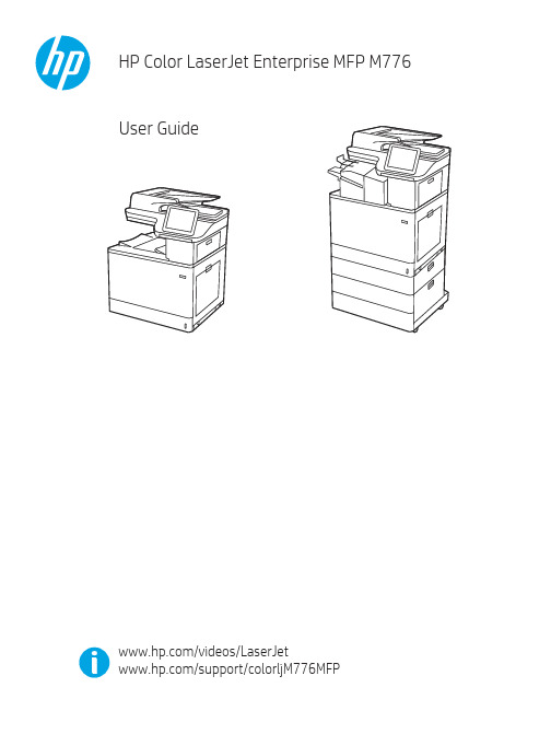
Legal informationCopyright and License© Copyright 2019 HP Development Company, L.P.Reproduction, adaptation, or translation without prior written permission is prohibited, except as allowedunder the copyright laws.The information contained herein is subject to change without notice.The only warranties for HP products and services are set forth in the express warranty statementsaccompanying such products and services. Nothing herein should be construed as constituting anadditional warranty. HP shall not be liable for technical or editorial errors or omissions contained herein.Edition 1, 10/2019Trademark CreditsAdobe®, Adobe Photoshop®, Acrobat®, and PostScript® are trademarks of Adobe Systems Incorporated.Apple and the Apple logo are trademarks of Apple Inc., registered in the U.S. and other countries.macOS is a trademark of Apple Inc., registered in the U.S. and other countries.AirPrint is a trademark of Apple Inc., registered in the U.S. and other countries.Google™ is a trademark of Google Inc.Microsoft®, Windows®, Windows® XP, and Windows Vista® are U.S. registered trademarks of MicrosoftCorporation.UNIX® is a registered trademark of The Open Group.iiiT able of contents1 Printer overview (1)Warning icons (1)Potential shock hazard (2)Printer views (2)Printer front view (2)Printer back view (4)Interface ports (4)Control-panel view (5)How to use the touchscreen control panel (7)Printer specifications (8)T echnical specifications (8)Supported operating systems (11)Mobile printing solutions (12)Printer dimensions (13)Power consumption, electrical specifications, and acoustic emissions (15)Operating-environment range (15)Printer hardware setup and software installation (16)2 Paper trays (17)Introduction (17)Load paper to Tray 1 (multipurpose tray) (17)Load Tray 1 (multipurpose tray) (18)Tray 1 paper orientation (19)Use alternative letterhead mode (24)Enable Alternative Letterhead Mode by using the printer control-panel menus (24)Load paper to Tray 2 (24)Load Tray 2 (24)Tray 2 paper orientation (26)Use alternative letterhead mode (29)Enable Alternative Letterhead Mode by using the printer control-panel menus (29)Load paper to the 550-sheet paper tray (30)Load paper to the 550-sheet paper tray (30)550-sheet paper tray paper orientation (32)Use alternative letterhead mode (35)Enable Alternative Letterhead Mode by using the printer control-panel menus (35)ivLoad paper to the 2 x 550-sheet paper trays (36)Load paper to the 2 x 550-sheet paper trays (36)2 x 550-sheet paper tray paper orientation (38)Use alternative letterhead mode (41)Enable Alternative Letterhead Mode by using the printer control-panel menus (41)Load paper to the 2,700-sheet high-capacity input paper trays (41)Load paper to the 2,700-sheet high-capacity input paper trays (41)2,700-sheet HCI paper tray paper orientation (43)Use alternative letterhead mode (45)Enable Alternative Letterhead Mode by using the printer control-panel menus (45)Load and print envelopes (46)Print envelopes (46)Envelope orientation (46)Load and print labels (47)Manually feed labels (47)Label orientation (48)3 Supplies, accessories, and parts (49)Order supplies, accessories, and parts (49)Ordering (49)Supplies and accessories (50)Maintenance/long-life consumables (51)Customer self-repair parts (51)Dynamic security (52)Configure the HP toner-cartridge-protection supply settings (53)Introduction (53)Enable or disable the Cartridge Policy feature (53)Use the printer control panel to enable the Cartridge Policy feature (54)Use the printer control panel to disable the Cartridge Policy feature (54)Use the HP Embedded Web Server (EWS) to enable the Cartridge Policy feature (54)Use the HP Embedded Web Server (EWS) to disable the Cartridge Policy feature (55)Troubleshoot Cartridge Policy control panel error messages (55)Enable or disable the Cartridge Protection feature (55)Use the printer control panel to enable the Cartridge Protection feature (56)Use the printer control panel to disable the Cartridge Protection feature (56)Use the HP Embedded Web Server (EWS) to enable the Cartridge Protection feature (56)Use the HP Embedded Web Server (EWS) to disable the Cartridge Protection feature (57)Troubleshoot Cartridge Protection control panel error messages (57)Replace the toner cartridges (58)T oner-cartridge information (58)Remove and replace the cartridges (59)Replace the imaging drums (62)Imaging drum information (62)Remove and replace the imaging drums (63)Replace the toner-collection unit (66)T oner-collection unit information (66)vRemove and replace the toner-collection unit (67)Replace the staple cartridge (M776zs model only) (70)Staple cartridge information (70)Remove and replace the staple cartridge (71)4 Print (73)Print tasks (Windows) (73)How to print (Windows) (73)Automatically print on both sides (Windows) (74)Manually print on both sides (Windows) (74)Print multiple pages per sheet (Windows) (75)Select the paper type (Windows) (75)Additional print tasks (76)Print tasks (macOS) (77)How to print (macOS) (77)Automatically print on both sides (macOS) (77)Manually print on both sides (macOS) (77)Print multiple pages per sheet (macOS) (78)Select the paper type (macOS) (78)Additional print tasks (79)Store print jobs on the printer to print later or print privately (79)Introduction (79)Create a stored job (Windows) (79)Create a stored job (macOS) (80)Print a stored job (81)Delete a stored job (81)Delete a job that is stored on the printer (81)Change the job storage limit (82)Information sent to printer for Job Accounting purposes (82)Mobile printing (82)Introduction (82)Wi-Fi, Wi-Fi Direct Print, NFC, and BLE printing (82)Enable wireless printing (83)Change the Wi-Fi Direct name (83)HP ePrint via email (83)AirPrint (84)Android embedded printing (85)Print from a USB flash drive (85)Enable the USB port for printing (85)Method one: Enable the USB port from the printer control panel (85)Method two: Enable the USB port from the HP Embedded Web Server (network-connectedprinters only) (85)Print USB documents (86)Print using high-speed USB 2.0 port (wired) (86)Method one: Enable the high-speed USB 2.0 port from the printer control panel menus (86)Method two: Enable the high-speed USB 2.0 port from the HP Embedded Web Server (network-connected printers only) (87)vi5 Copy (88)Make a copy (88)Copy on both sides (duplex) (90)Additional copy tasks (92)6 Scan (93)Set up Scan to Email (93)Introduction (93)Before you begin (93)Step one: Access the HP Embedded Web Server (EWS) (94)Step two: Configure the Network Identification settings (95)Step three: Configure the Send to Email feature (96)Method one: Basic configuration using the Email Setup Wizard (96)Method two: Advanced configuration using the Email Setup (100)Step four: Configure the Quick Sets (optional) (104)Step five: Set up Send to Email to use Office 365 Outlook (optional) (105)Introduction (105)Configure the outgoing email server (SMTP) to send an email from an Office 365 Outlookaccount (105)Set up Scan to Network Folder (108)Introduction (108)Before you begin (108)Step one: Access the HP Embedded Web Server (EWS) (108)Step two: Set up Scan to Network Folder (109)Method one: Use the Scan to Network Folder Wizard (109)Method two: Use Scan to Network Folder Setup (110)Step one: Begin the configuration (110)Step two: Configure the Scan to Network Folder settings (111)Step three: Complete the configuration (118)Set up Scan to SharePoint (118)Introduction (118)Before you begin (118)Step one: Access the HP Embedded Web Server (EWS) (118)Step two: Enable Scan to SharePoint and create a Scan to SharePoint Quick Set (119)Scan a file directly to a SharePoint site (121)Quick Set scan settings and options for Scan to SharePoint (122)Set up Scan to USB Drive (123)Introduction (124)Step one: Access the HP Embedded Web Server (EWS) (124)Step two: Enable Scan to USB Drive (124)Step three: Configure the Quick Sets (optional) (125)Default scan settings for Scan to USB Drive setup (126)Default file settings for Save to USB setup (126)Scan to email (127)Introduction (127)Scan to email (127)Scan to job storage (129)viiIntroduction (129)Scan to job storage on the printer (130)Print from job storage on the printer (132)Scan to network folder (132)Introduction (132)Scan to network folder (132)Scan to SharePoint (134)Introduction (134)Scan to SharePoint (134)Scan to USB drive (136)Introduction (136)Scan to USB drive (136)Use HP JetAdvantage business solutions (138)Additional scan tasks (138)7 Fax (140)Set up fax (140)Introduction (140)Set up fax by using the printer control panel (140)Change fax configurations (141)Fax dialing settings (141)General fax send settings (142)Fax receive settings (143)Send a fax (144)Additional fax tasks (146)8 Manage the printer (147)Advanced configuration with the HP Embedded Web Server (EWS) (147)Introduction (147)How to access the HP Embedded Web Server (EWS) (148)HP Embedded Web Server features (149)Information tab (149)General tab (149)Copy/Print tab (150)Scan/Digital Send tab (151)Fax tab (152)Supplies tab (153)Troubleshooting tab (153)Security tab (153)HP Web Services tab (154)Networking tab (154)Other Links list (156)Configure IP network settings (157)Printer sharing disclaimer (157)View or change network settings (157)Rename the printer on a network (157)viiiManually configure IPv4 TCP/IP parameters from the control panel (158)Manually configure IPv6 TCP/IP parameters from the control panel (158)Link speed and duplex settings (159)Printer security features (160)Introduction (160)Security statements (160)Assign an administrator password (160)Use the HP Embedded Web Server (EWS) to set the password (160)Provide user access credentials at the printer control panel (161)IP Security (161)Encryption support: HP High Performance Secure Hard Disks (161)Lock the formatter (161)Energy-conservation settings (161)Set the sleep timer and configure the printer to use 1 watt or less of power (161)Set the sleep schedule (162)Set the idle settings (162)HP Web Jetadmin (163)Software and firmware updates (163)9 Solve problems (164)Customer support (164)Control panel help system (165)Reset factory settings (165)Introduction (165)Method one: Reset factory settings from the printer control panel (165)Method two: Reset factory settings from the HP Embedded Web Server (network-connectedprinters only) (166)A “Cartridge is low” or “Cartridge is very low” message displays on the printer control panel (166)Change the “Very Low” settings (166)Change the “Very Low” settings at the control panel (166)For printers with fax capability (167)Order supplies (167)Printer does not pick up paper or misfeeds (167)Introduction (167)The printer does not pick up paper (167)The printer picks up multiple sheets of paper (171)The document feeder jams, skews, or picks up multiple sheets of paper (174)Clear paper jams (174)Introduction (174)Paper jam locations (174)Auto-navigation for clearing paper jams (175)Experiencing frequent or recurring paper jams? (175)Clear paper jams in the document feeder - 31.13.yz (176)Clear paper jams in Tray 1 (13.A1) (177)Clear paper jams in Tray 2 (13.A2) (182)Clear paper jams in the fuser (13.B9, 13.B2, 13.FF) (188)ixClear paper jams in the duplex area (13.D3) (194)Clear paper jams in the 550-sheet trays (13.A3, 13.A4) (199)Clear paper jams in the 2 x 550 paper trays (13.A4, 13.A5) (206)Clear paper jams in the 2,700-sheet high-capacity input paper trays (13.A3, 13.A4, 13.A5, 13.A7) (213)Resolving color print quality problems (220)Introduction (220)Troubleshoot print quality (221)Update the printer firmware (221)Print from a different software program (221)Check the paper-type setting for the print job (221)Check the paper type setting on the printer (221)Check the paper type setting (Windows) (221)Check the paper type setting (macOS) (222)Check toner-cartridge status (222)Step one: Print the Supplies Status Page (222)Step two: Check supplies status (222)Print a cleaning page (222)Visually inspect the toner cartridge or cartridges (223)Check paper and the printing environment (223)Step one: Use paper that meets HP specifications (223)Step two: Check the environment (223)Step three: Set the individual tray alignment (224)Try a different print driver (224)Troubleshoot color quality (225)Calibrate the printer to align the colors (225)Troubleshoot image defects (225)Improve copy image quality (233)Check the scanner glass for dirt and smudges (233)Calibrate the scanner (234)Check the paper settings (235)Check the paper selection options (235)Check the image-adjustment settings (235)Optimize copy quality for text or pictures (236)Edge-to-edge copying (236)Improve scan image quality (236)Check the scanner glass for dirt and smudges (237)Check the resolution settings (238)Check the color settings (238)Check the image-adjustment settings (239)Optimize scan quality for text or pictures (239)Check the output-quality settings (240)Improve fax image quality (240)Check the scanner glass for dirt and smudges (240)Check the send-fax resolution settings (242)Check the image-adjustment settings (242)Optimize fax quality for text or pictures (242)Check the error-correction setting (243)xSend to a different fax machine (243)Check the sender's fax machine (243)Solve wired network problems (244)Introduction (244)Poor physical connection (244)The computer is unable to communicate with the printer (244)The printer is using incorrect link and duplex settings for the network (245)New software programs might be causing compatibility problems (245)The computer or workstation might be set up incorrectly (245)The printer is disabled, or other network settings are incorrect (245)Solve wireless network problems (245)Introduction (245)Wireless connectivity checklist (245)The printer does not print after the wireless configuration completes (246)The printer does not print, and the computer has a third-party firewall installed (246)The wireless connection does not work after moving the wireless router or printer (247)Cannot connect more computers to the wireless printer (247)The wireless printer loses communication when connected to a VPN (247)The network does not appear in the wireless networks list (247)The wireless network is not functioning (247)Reduce interference on a wireless network (248)Solve fax problems (248)Checklist for solving fax problems (248)What type of phone line are you using? (249)Are you using a surge-protection device? (249)Are you using a phone company voice-messaging service or an answering machine? (249)Does your phone line have a call-waiting feature? (249)Check fax accessory status (249)General fax problems (250)The fax failed to send (250)No fax address book button displays (250)Not able to locate the Fax settings in HP Web Jetadmin (250)The header is appended to the top of the page when the overlay option is enabled (251)A mix of names and numbers is in the recipients box (251)A one-page fax prints as two pages (251)A document stops in the document feeder in the middle of faxing (251)The volume for sounds coming from the fax accessory is too high or too low (251)Index (252)xiPrinter overview1Review the location of features on the printer, the physical and technical specifications of the printer,and where to locate setup information.For video assistance, see /videos/LaserJet.The following information is correct at the time of publication. For current information, see /support/colorljM776MFP.For more information:HP's all-inclusive help for the printer includes the following information:●Install and configure●Learn and use●Solve problems●Download software and firmware updates●Join support forums●Find warranty and regulatory informationWarning iconsUse caution if you see a warning icon on your HP printer, as indicated in the icon definitions.●Caution: Electric shock●Caution: Hot surface●Caution: Keep body parts away from moving partsPrinter overview1●Caution: Sharp edge in close proximity●WarningPotential shock hazardReview this important safety information.●Read and understand these safety statements to avoid an electrical shock hazard.●Always follow basic safety precautions when using this product to reduce risk of injury from fire orelectric shock.●Read and understand all instructions in the user guide.●Observe all warnings and instructions marked on the product.●Use only a grounded electrical outlet when connecting the product to a power source. If you do notknow whether the outlet is grounded, check with a qualified electrician.●Do not touch the contacts on any of the sockets on the product. Replace damaged cordsimmediately.●Unplug this product from wall outlets before cleaning.●Do not install or use this product near water or when you are wet.●Install the product securely on a stable surface.●Install the product in a protected location where no one can step on or trip over the power cord.Printer viewsIdentify certain parts of the printer and the control panel.Printer front viewLocate features on the front of the printer.2Chapter 1 Printer overviewPrinter front view3Printer back viewLocate features on the back of the printer.Interface portsLocate the interface ports on the printer formatter. 4Chapter 1 Printer overviewControl-panel viewThe control panel provides access to the printer features and indicates the current status of the printer.NOTE:Tilt the control panel for easier viewing.The Home screen provides access to the printer features and indicates the current status of the printer.screens.NOTE:The features that appear on the Home screen can vary, depending on the printerconfiguration.Control-panel view5Figure 1-1Control-panel view?i 12:42 PM6Chapter 1 Printer overviewHow to use the touchscreen control panelPerform the following actions to use the printer touchscreen control panel.T ouchT ouch an item on the screen to select that item or open that menu. Also, when scrolling T ouch the Settings icon to open the Settings app.How to use the touchscreen control panel 7SwipeT ouch the screen and then move your finger horizontally to scroll the screen sideways.Swipe until the Settings app displays.Printer specificationsDetermine the specifications for your printer model.IMPORTANT:The following specifications are correct at the time of publication, but they are subject to change. For current information, see /support/colorljM776MFP .T echnical specificationsReview the printer technical specifications.Product numbers for each model ●M776dn - #T3U55A ●Flow M776z - #3WT91A ●Flow M776zs - #T3U56APaper handling specificationsPaper handling features Tray 1 (100-sheet capacity)Included Included Included Tray 2 (550-sheet capacity)IncludedIncludedIncluded8Chapter 1 Printer overview550-sheet paper trayOptional Included Not included NOTE:The M776dn models accept one optional550-sheet tray.Optional Included Included2 x 550-sheet paper tray and standNOTE:The M776dn models accept one optional550-sheet tray that may be installed on top of thestand.Optional Not included Not included2,700-sheet high-capacity input (HCI) paper trayand standNOTE:The M776dn models accept one optional550-sheet tray that may be installed on top of theoptional printer stand.Printer standOptional Not included Not included NOTE:The M776dn models accept one optional550-sheet tray that may be installed on top of theoptional printer stand.Inner finisher accessory Not included Not included Included Automatic duplex printing Included IncludedIncludedIncluded Included Included10/100/1000 Ethernet LAN connection with IPv4and IPv6Hi-Speed USB 2.0Included Included IncludedIncluded Included IncludedEasy-access USB port for printing from a USBflash drive or upgrading the firmwareIncluded Included Included Hardware Integration Pocket for connectingaccessory and third-party devicesHP Internal USB Ports Optional Optional OptionalOptional Optional OptionalHP Jetdirect 2900nw Print Server accessory forWi-Fi connectivity and an additional Ethernet portOptional IncludedIncludedHP Jetdirect 3100w accessory for Wi-Fi, BLE, NFC,and proximity badge readingPrints 45 pages per minute (ppm) on Letter-sizepaper and 46 ppm on A4-size paperEasy-access USB printing for printing from a USBIncluded Included Includedflash driveT echnical specifications9Included Included Included Store jobs in the printer memory to print later orprint privatelyScans 100 pages per minute (ppm) on A4 andIncluded Included Included letter-size paper one-sidedIncluded Included Included 200-page document feeder with dual-headscanning for single-pass duplex copying andscanningNot included Included Included HP EveryPage T echnologies including ultrasonicmulti-feed detectionNot included Included Included Embedded optical character recognition (OCR)provides the ability to convert printed pages intotext that can be edited or searched using acomputerIncluded Included Included SMART Label feature provides paper-edgedetection for automatic page croppingIncluded Included Included Automatic page orientation for pages that haveat least 100 characters of textIncluded Automatic tone adjustment sets contrast,Included Includedbrightness, and background removal for eachpageIncluded Included Includedfolders on a networkIncludedSend documents to SharePoint®Included IncludedIncluded Included Included NOTE:Memory reported on the configurationpage will change from 2.5 GB to 3 GB with theoptional 1 GB SODIMM installed.Mass storage: 500 GB hard disk drive Included Included IncludedSecurity: HP Trusted Platform Module (TPM)Included Included IncludedT ouchscreen control panel Included Included IncludedRetractable keyboard Not included Included Included 10Chapter 1 Printer overviewFax Optional Included IncludedSupported operating systemsUse the following information to ensure printer compatibility with your computer operating system.Linux: For information and print drivers for Linux, go to /go/linuxprinting.UNIX: For information and print drivers for UNIX®, go to /go/unixmodelscripts.The following information applies to the printer-specific Windows HP PCL 6 print drivers, HP print driversfor macOS, and to the software installer.Windows: Download HP Easy Start from /LaserJet to install the HP print driver. Or, go tothe printer-support website for this printer: /support/colorljM776MFP to download the printdriver or the software installer to install the HP print driver.macOS: Mac computers are supported with this printer. Download HP Easy Start either from /LaserJet or from the Printer Support page, and then use HP Easy Start to install the HP print driver.1.Go to /LaserJet.2.Follow the steps provided to download the printer software.Windows 7, 32-bit and 64-bit The “HP PCL 6” printer-specific print driver is installed for this operating system aspart of the software installation.Windows 8.1, 32-bit and 64-bit The “HP PCL-6” V4 printer-specific print driver is installed for this operating systemas part of the software installation.Windows 10, 32-bit and 64-bit The “HP PCL-6” V4 printer-specific print driver is installed for this operating systemas part of the software installation.Windows Server 2008 R2, SP 1, 64-bit The PCL 6 printer-specific print driver is available for download from the printer-support website. Download the driver, and then use the Microsoft Add Printer tool toinstall it.Windows Server 2012, 64-bit The PCL 6 printer-specific print driver is available for download from the printer-support website. Download the driver, and then use the Microsoft Add Printer tool toinstall it.Windows Server 2012 R2, 64-bit The PCL 6 printer-specific print driver is available for download from the printer-support website. Download the driver, and then use the Microsoft Add Printer tool toinstall it.Windows Server 2016, 64-bit The PCL 6 printer-specific print driver is available for download from the printer-support website. Download the driver, and then use the Microsoft Add Printer tool toinstall it.Windows Server 2019, 64-bit The PCL 6 printer-specific print driver is available for download from the printer-support website. Download the driver, and then use the Microsoft Add Printer tool toinstall it.Supported operating systems11macOS 10.13 High Sierra, macOS 10.14 MojaveDownload HP Easy Start from /LaserJet , and then use it to install the print driver.NOTE:Supported operating systems can change.NOTE:For a current list of supported operating systems and HP’s all-inclusive help for the printer, go to /support/colorljM776MFP .NOTE:For details on client and server operating systems and for HP UPD driver support for this printer, go to /go/upd . Under Additional information , click Specifications .●Internet connection●Dedicated USB 1.1 or 2.0 connection or a network connection● 2 GB of available hard-disk space ●1 GB RAM (32-bit) or2 GB RAM (64-bit)●Internet connection●Dedicated USB 1.1 or 2.0 connection or a network connection●1.5 GB of available hard-disk spaceNOTE:The Windows software installer installs the HP Smart Device Agent Base service. The file size is less than 100 kb. Its only function is to check for printers connected via USB hourly. No data is collected. If a USB printer is found, it then tries to locate a JetAdvantage Management Connector (JAMc) instance on the network. If a JAMc is found, the HP Smart Device Agent Base is securelyupgraded to a full Smart Device Agent from JAMc, which will then allow printed pages to be accounted for in a Managed Print Services (MPS) account. The driver-only web packs downloaded from for the printer and installed through the Add Printer wizard do not install this service.T o uninstall the service, open the Control Panel , select Programs or Programs and Features , and then select Add/Remove Programs or Uninstall a Programto remove the service. The file name isHPSmartDeviceAgentBase.Mobile printing solutionsHP offers multiple mobile printing solutions to enable easy printing to an HP printer from a laptop, tablet, smartphone, or other mobile device.T o see the full list and to determine the best choice, go to /go/MobilePrinting .NOTE:Update the printer firmware to ensure all mobile printing capabilities are supported.●Wi-Fi Direct (wireless models only, with HP Jetdirect 3100w BLE/NFC/Wireless accessory installed)●HP ePrint via email (Requires HP Web Services to be enabled and the printer to be registered with HP Connected)●HP Smart app ●Google Cloud Print12Chapter 1 Printer overview。
DEC OS-8 场外维修指南说明书

FIELD SERVICE SOFTWARE ASSISTANCE BROCHURE O S - 8Prepared by:Rick MooreINTRODUCTIONThis is a reference document for Field Service use in diagnosing system problems. The information presented in this chapter is extracted from various OS-8 reference manuals and literature which are listed in the appendix.It is not intended to be a course on OS-8 or a substitute for standard DEC software manuals. However, the topics presented here are some of the more commonly used features and some of the commands that should help you to better serve your customer through an enhanced knowledge of his OS-8 operating system.It is strongly recommended that you be extremely careful using your customer's software as a little knowledge is a dangerous thing. If you do work on a customer's files, be sure to use copies of his system only. Tell him what you feel the problem is and let him take any corrective action.OS-8 consists of an executive and library of system programs which reside on a mass storage device called a "system device". This could be a disk, dectape or floppy unit. The executive supervises the overall program processing and consists of the following four major components:- Keyboard monitor ( KMON )- Command Decoder ( CD )- Device Handlers- User Service Routine ( USR )The Keyboard Monitor provides communications between the user and the OS-8 Executive. The root segment of the monitor resides perminently in memory and occupies 256 words. Commands from the console terminal are interperted and whenever needed, the CommandDecoder, USR, KMON, and ODT are brought into memory in a series of overlays while the contents of the memory used is swapped out to the system scratch area. In this manner it is possible to run a baseline system in only 8K words of memory.The commands that are executed directly from the KMON are:ASsign - assigns a new, user defined device name to a perminant device.DEASsign - restores perminant device namesGET - loads core image files into memory from a deviceSTART - starts execution of a program already in memoryRUn - loads core image (.SV) files into memory from a device and starts executionR - loads core image (.SV) files into memory from the SYStem device and starts executionSAve - creates core image programs on a deviceODt - invokes the Octal Debugging TechniqueDAte - sets / prints the system dateThe Command Decoder is called when a system program needs additional information from the operator concerning files to be acted upon or devices to be used. You are in the Command Decoder whenever the prompt character "*" is issued.Understanding the Command Decoder line format is probably the most important step to successful usage of the OS-8 Operating System. It is as follows:*OUTDEV:OUTFIL.EX<INDEV:INFILE.EX,INFILE.EX/SW1/SW2=N... to translate ...OUTDEV: - the output device (SYS:,RKB0:,DTA0:,LPT:) OUTFIL.EX - the name of the output file and it's extension INDEV: - the input deviceINFILE.EX - the name of the input file and the extensionSW? - an optional switch ... differint for each program=N - numerical value (ie: in direct =N# of columns)There may be 0-3 input files, 0-9 output files, 0-3 option switches, depending on the requirements of the individual program. In several programs, it is not necessary to specify every detail ...certain programs have default values for devices, switches, etc. The only way to be sure of this is to know the program you are working with.Again, the value of learning the command decoder format cannot be overstressed ... the same basic format is used thoughout DEC software. (ie: RT-11, RSTS, etc.)Device Handlers are subroutines which handle data transfer to and from peripheral devices. Device handlers for the particular hardware system you are using are activated by the program "BUILD". These subroutines are then available to all OS-8 programs. It is through the use of device handlers that a sort of "device independence" is acheived.The USR is a collection of subroutines that perform operations of opening and closing files, loading device handlers, program chaining, and calling the CD. The USR provides these functions not only for the system itself, but for any programs running under OS-8.INITIALIZING OS-8Mount the OS-8 System on the appropriate hardware and execute the bootstrap. This may be as simple as pressing a "BOOT" button or require a toggle-in program from the operator's console. Various bootstraps are listed in the appendix.After the bootstrap is executed, the monitor will print a dot "." on the console. At this point, KMON is active and the system is ready to accept one of the monitor level commands listed on page 1.CCLThe Concise Command Language ia a means of providing an easy to understand "English-like" command interface between the operator and the monitor. It translates the commands, chains to the appropriate system programs, passes arguments and filespecs, and starts execution. Any CCL command can be simulated by typing the necessary monitor and CD responses manually. For example:.DIR is equivalent to .R DIRECT*TTY:<SYS:/E=2.COPY RXA1:<RKA0: is equivalent to .R FOTP*RXA1:*.*<RKA0:*.*The use of CCL is optional in OS-8; manditory in OS-78. This is because you cannot normally access monitor level commands in OS-78. There is a way around this; by typing ".SET SYS OS8" it is possible to turn on this attribute.GETTING DIRECTORIES.DIR - types directory of system device on the console.DIR-L - prints directory of system device on line printer.DIR RKB0:-L - prints directory of device RKB0 on line printerSETThe program "SET.SV" is called by the ".SET" CCL command and can be used to modify some of the attributes of the various device handlers. Some useful ones are:.SET SYS OS8 - allows monitor level commands in OS-78..SET SYS OS78 - normal OS-78 mode; CCL commands only.SET SYS INIT - causes the command file "INIT.CM" to be executed upon boot-up..SET SYS INIT [cmd] - causes the command [cmd] to be executed upon boot-up..SET SYS NO INIT - negates the above.SET LPT LA78 - allows PDP-8A (M8316) parrallel port as controller for LA-180 (device code=0570).SET LPT LA8A - restores LPT to normal 0660 device code.SET TTY SCOPE - causes a rubout to actually erase the character from the screen..SET TTY NO SCOPE - causes the rubout to echo the character/slash combination for hardcopy terminals..SET TTY PAUSE - causes the terminal to pause every "height" lines for ease of reading..SET TTY HEIGHT 24 - tells the handler the screen has 24 lines.SET TTY WIDTH 80 - allows 80 character width to VT52 screen*** WARNING ***The command ".SET SYS NO INIT" must be given before attempting to use the "BUILD" program, since execution of the "INIT.CM" file or any CCL command will cause the previous contents of memory and the system scratch area to be altered. Also, since the process of executing this file may entail several overlays, the usefullness of it on any media except disks or diskettes is questionable.OS-8 FILESThere are three standard types of OS-8 file formats used by OS-8 and associated system programs; ASCII, Binary and Core Image (.SV).ASCII and Binary files are packed three characters to every two 12 bit words as follows:-----------------------------------------------| | |Word 1 | Char. 3 | Character 1 || (bits 0-3) | (bits 0-7) || | |-----------------------------------------------| | |Word 2 | Char. 3 | Character 2 || (bits (4-7) | (bits 0-7) || | |-----------------------------------------------0 - 3 4 - 11In Binary files, the binary data must be preceded by one or more frames of leader/trailer code (ASCII 200 code). The first character must be either 100-177 octal (origin setting for absolute binary files), 240-257 octal (a COMMON declaration frame for relocatable binary files), or 300 octal which is an origin setting. The end of binary data is one or more frames of leader trailer code. ASCII and Binary files are terminated by a CTRL/Z code (ACSII 232).A Core Image file consists of a header followed by the actual core image. The header is called the Core Control Block (CCB). It consists of first 128 words of the first block (256 words) of the file. The CCB is a table of information that contains the length of the file, the program's starting address, and the Job Status Word (JSW). The CCB for a program at the time it is loaded into core is always saved in words 200-377 (octal) of block 37 on the system's scratch area. It is placed there by the GET or RUN operations or by the ABSLDR program. This information is then used when performing a SAVE without arguments.FILE NAMES and EXTENSIONSFiles are referenced symbolically by a name of up to six characters followed, optionally, by a period and a two character extension. The extension to a file name is generally used to type the files according to their formats or defaults to particular system programs.In most cases, the user will want to conform to the standard file name extensions established for OS-8. If the extension is not specified for a files, some system programs will append an assumed extension by default. This default extension can be overidden by stating the extension in the CD line explicedly.The most common OS-8 standard default extensions are:SV - core image programsBN - binary programsPA - PAL8 assembly language sourcesBA - BASIC source filesBI - BATCH control filesSY - system headsDG - diagnostic program **BX - DECX8 exercisor modules **X8 - customised DECX8 system exercisor **** refers to psuedo standards imposed by the New England District PDP-8 Diagnostic System.FILE MANIPULATIONSFiles can be transfered between OS-8 devices by using either "FOTP.SV" (File Oriented Transfer Program) or "PIP.SV" (Peripheral Interchange Program) or the CCL commands that call them. These commands and their uses are:COPy - copies files from one device to anotherDELete - deletes files from a deviceLIst - lists an ASCII files on the LPTREName - changes the name of a file in the directory SQuish - eliminates all empty and deleted files on a deviceTYpe - types an ASCII file on the console terminal ZERO - zeroes the directory of a device, deleting all existing files on that deviceFor example, to copy file FOO.PA from RXA1: to RKB0:.COPY RKB0:<RXA1:FOO.PA( note the similiarity between this and the format ofthe Command Decoder Line on page 2.)To copy an entire device using PIP and FOTP type:.R PIP first transfer the system heads *RKA1:<RKA0:/Y/Z*RKB1:<RKB0:/Y/Z.R FOTP now all the files*RKA1:<RKA0:*.* using wildcard transfers*RKB1:<RKB0:*.*For floppies, it is easier since the program "RXCOPY.SV" or the CCL command ".DUPLicate" will copy the entire device.SYSTEM HEADSThe "/Y" option of PIP.SV can be used for system head manipulation. A system head is 50 blocks long and is located at the beginning of the system device. It contains the system bootstrap, the monitor, and all its overlays. System heads are sometimes stored as files on a device for ease of use with the extension ".SY".To move a system head:.R PIP*RKA1:<RKA0:/Yif "RKA1" is a virgin device, a skeleton directory must be created, so type:*RKA1:<RKA0:/Y/ZUSING WILDCARDSCertain commands allow wildcards in the file name specifications. These commands are COPY, DELETE, DIRECT, LIST, RENAME, and TYPE.Wildcards allow a filename or extension to be totally replaced with an asterisk (*) or partially repalced with a question mark (?). Wildcards are particularly useful when doing multiple file transfers. This is illustrated in the following examples:TEST1.* - all files with the name TEST1 and any extension*.BN - all files with a BN extension and any name*.* - all files with any name and any extensionTEST2.B? - all files with the name TEST2 and any extension starting with a BTES??.PA - all files with a PA extension and any name from 3 to 5 characters beginning with TESthe asterisk amd question mark can be used together.* - all files with any extension and with file names of three characters or lessBUILDThe program "BUILD.SV" is the system generation program for OS-8 which allows the user to:1. Maintain and update device handlers in an existing OS-8 system.2. Add device handlers to a new or existing system.3. Change the system characteristics to reflect hardware modifications.Device handlers are supplied with the OS-8 system and are in the format of Binary (.BN) files.To run the Build program, type:.RUN SYS BUILDNOTE:It is important that the user specify the "RUN" command, rather than the "R" command when loading BUILD into core. This will allow the CCB to be stored on the system scratch area for use with the SAVE command!Also, since the system scratch area is used at times when the "INIT.CM" file is executed, it is imperative that the command ".SET SYS NO INIT" be given prior to beginning the BUILD process. After the program is SAVEd, ".SET SYS INIT" can be reinstituted.This matter cannot be overemphisized ... SAving "BUILD" without these precautions will appear to work and the system will boot without failure, however, the next time BUILD is run, it will not work! This is because the proper CCB parameters will have been lost.RUNNING BUILDChanging a system's parameters can be a complicated procedure with too many variables to be explained in this document. For complete instructions on BUILD, see the appropriated OS-8 Manual.- DEVICESSome of the devices that are available in the OS-8 system are:SYS: - the system deviceDSK: - the default device (usually SYS:)RKA0: - "A" side of RK05 drive #0RKB0: - "B" side of RK05 drive #0TTY: - console teletypeLPT: - line printerLQP: - letter quality printer (Diablo)PTR: - paper tape readerPTP: - paper tape punchDTA0: - dectape drive #0DTA1: - dectape drive #1RXA0: - RX01 floppy drive #0RXA1: - RX01 floppy drive #1RL0A: - RL01 area "A" drive 0RL0B: - RL01 area "B" drive 0RL0C: - RL01 area "C" drive 0FUTILThe OS-8 File UTILity program was orginally developed by Jim Crapuchettes of Menlo Computer Associate,Inc., Menlo Park, CA. It is now included within the OS-8 Extension Kit after release V3D, and is also contained on the New England District PDP-8 Diagnostic System after release V8.04.FUTIL enables a user to examine and modify the contents of mass storage devices, including the SYStem device, and is therefore as dangerous as it is useful! It can be used to recover damaged files, repair destroyed directories, patch programs on the mass storage device, and check for bad blocks on the device.It is this last feature that is particularly useful to us in Field Service as we often have questions concerning the validity of a customer's disk or diskette. The following procedure can verify this:.R FUTILSET DEVICE RXA0 floppy drive 0 is the target deviceSCAN 0-755 scans the 756 (octal) blocks on the deviceEXIT returns to OS-8If any bad blocks were encountered, the program would reportBAD BLOCK nnn where "nnn" was faultyThe cause of this could be due to either a bad CRC character due to blown data (can be recopied) or blown format (device must be reformatted). In the case of floppies, the later condition is fatal as they cannot be reformatted.FUTIL can be used to scan devices regardless of their program contents, for example, OS-8, COS 300, or any customer written file structure can be scanned, as long as standard sector format is used.to SCAN an RK05 Disk:.R FUTILSET DEVICE RKA0 or RKA1, etc.SCAN 0-6257 there are 6260 blocksSET DEVICE RKB0 now the other sideSCAN 0-6257EXIT.NOTE:At this time, a note on the "sides" of a disk is in order. The RK05 is broken up into two (2) logical devices called "RKA0" and "RKB0" as the RL01 is broken into three (3) devices called "RL0A", RL0B", and "RL0C" by OS-8. This is because of the system's inability to address the entire disk and the limited number of entries the directories can hold.These "sides" are actually not physical sides (who ever heard of a three sided RL01), but refer (on the RK05) to the first 6260 sectors as "RKA0" and the remaining 6260 sectors as "RKB0". A look at the hardware shows that after the sector counter overflows (at 16 sectors) the heads switch to the other surface. After the sector counter overflows again, the heads switch back and then the cylinder address increments. Thus RKA0 is on the outer tracks of the disk and RKB0 is on the inner tracks.。
Study on Japanese Culture in Tora-san Series Films
Study on Japanese Culture in Tora-san Series FilmsQin Wang1,21School of Foreign Languages,Yan’an University2Graduate School of Integrated Science and Art,University of East Asia, Yamaguchi,JapanAbstract: The comedy directed by Mr. Yoji Yamada, named The Story of Tora-san, is well-known in Japan, and even has a certain influence in Asia and even the world. The reason why the play was so successful was not only rely on it’s humor, but also it’s complete differences from Hollywood, showing the unique social conflicts and family conflicts in Japan, reflecting the unique local customs and the most real Japanese traditional culture, which makes the Japanese audience laugh and has a long-term gratitude and triggers their deep thinking. A study on the Tora-san Series Films is equal to a study of the most real Japanese traditional culture.Keywords: Tora-san; Film; Japanese culture; ResearchDOI:10.47297/ wsprolaadWSP2634-786504.202203011. IntroductionI n 1990, the Japanese went to the Berlin International Film Festival with confidence with the “Tora-san series films”. But to the surprise of the Japanese, it was rejected soon. The reason was that foreigners could not understand why Japanese people were so obsessed to watch “Tora-san”. Although “Tora-san” was not as popular abroad as it was in Japan, and even some foreigners cannot understand why “Tora-san” was so popular in the hearts of Japanese people, even though it was thwarted at the Berlin International Film Festival. But for Japanese people, even if Tora-san dis not receive recognition and understanding abroad, it would not affect Japanese people’s love for Tora-san and their obsession with Tora-san in the slightest. Because in the hearts of Japanese people, “Tora-san” is actually the traditional culture of Japanese people, which shows how unshakable the status of “Tora-san” is in the minds of Japanese people.About the Author: Qin Wang was born in Yan’an, Shaanxi Province, China, in 1984. She is a Associate Professor in the School of Foreign Languages, Yan’an University, China. She as a PhD candidate now, studying in University of East Asia , Japan. Research direction is Japanese culture.Funded project: This research results has been financed by the Horizontal Project of Shaanxi Star Vision Film Co. LTD 《A research on Japanese culture in “ Tora-san “ film series》(YD2019036).Research on Literary and Art Development Vol.3 No.1 20222. Background of The Story of Tora-san(1) The Great Cultural Revolution in JapanThe first episode of “The Story of Tora-san” was broadcast in 1969 and the last episode was broadcast in 1995, and the whole series lasted 26 years. The film was recorded until the death of Mr. Kiyoshi Watami, who played the lead role of Tora-san. From 1960 to 1979, during the Great Cultural Revolution in China, Japan also saw the Cultural Revolution, which was a cultural revolution that celebrated Mao Zedong’s thought and opposed American imperialism. It was a cultural revolutionary movement that celebrated Mao Zedong’s thought and opposed U.S. imperialism, which was also the “left-wing movement” in Japan. At the beginning of the Cultural Revolution in Japan, students’ movements were the mainstream, and in the 1960s, when the student movement reached a low ebb, the Japanese Red Army took over the banner, and the suppressed Red Army was a microcosm of the society at that time. For many Japanese youth at that time, U.S. imperialism was the symbol of evil and China was the symbol of revolution, and Chairman Mao was the common mentor of all revolutionary youth in the world. It was not until 1979, when China entered the period of reform and opening up, that the external spiritual support for the left-wing youth in Japan was cut off, and the left-wing movements in Japan gradually fell into a low point and eventually disappeared historically.(2) Japan’s “Bubble Economy”From late 1980s to the early 1990s in Japan, Japan experienced the second rapid economic development period after 1960s, which was due to the support of a lot of opportunities, and hit the highest peak of economic development in 1989. But there is no corresponding industrial support, so it looks like bubble, and is later called “bubble economy”. Because of this, in the early 1990s, after the collapse of the bubble, Japanese economy collapsed, which led to a large number of Japanese people losing their jobs and the living conditions of the ordinary people. The ten years after that, the Japanese economy was in a depression of almost 0 growth.3. Japanese Culture in The Story of Tora-sanAlthough there are 48 films in the series of “Tora-san” so far, there are only three core themes running through the whole play: homesickness, travel and love.(1) HomesicknessTora-san appeared on the screen as a typical ordinary civilian with no rights, no status, and no money. The main character Tora-san ran away from home because of an quarrel with his family. He traveled away all the year round, and met all kinds of Japanese women with them. Although the ending was always helpless to break up without any result. However, Tora-san still left his hometown again with regret and set foot in the distance again. His love was undoubtedly a failure, but no matter how frustrated, there were still kind and lovely sisters and family waiting for him to go home in his hometown, tokuga District, Tokyo. He was stubborn and not sophisticated, but his family was always sincerely, tolerant and sincerely looking forward to his return. The little nest upstairs wasResearch on Literary and Art Development Vol.3 No.1 2022 always reserved for him, because it was his home, only because they were his family. However, Tora-san would still think about his sister Cherry Blossom’s happiness after marriage, whether Manman was still worrying about going to school, whether the family were in good health, and so on. Home and family are always spiritual harbors to depend on. Wasn’t it the “home” that Japanese audiences were looking for when the rapid industrialization of Japan led to the loss of family feeling and spiritual home? Perhaps it is because they touch the deepest heart of Japanese audiences that Japanese audiences find some kind of comfort and compensation in the Story of Tora-san.(2) TravelTora-san is a prodigal wandering around, but he still holds hope for life when he runs into a wall outside. Just as the Japanese like traveling, Japan is a big tourist country. Every year in the golden season of traveling, a large number of Japanese people travel around the country. They have a stunning variety of study trips, sightseeing trips and so on. Japan’s modern tourism is even a special scenic spot. The meaning of travel for most Japanese is not simply to watch or play, but to get the insight of life from what they see and think. It can also be said that travel is life. Life is a journey, even if travel is adventure, exploration, experience and growth. This is the lifestyle imprinted on the bones of Japanese people from ancient times to today, just like the wandering surfers. In this way, we can understand why the Japanese love Tora-san so much - because he yearned for freedom, and in these days of wandering around, he silently wrote about his happiness, his troubles and pains, which constitutes the chapter of his life. Although plain, this is a unique and irreplaceable life for him!(3) LoveThe story of the series always ends with his helpless breakup with his beloved woman and regrets that his love as a bottom-level people failed, which is also one of the core of the play, but at the same time, it also reflects the unique Japanese philosophical aesthetics, that is, the “Romantic Esthetics of Lost Love”, which also touches the hearts of many Japanese audiences. Just like Sakuragi Hanamichi in the later “SLAM DUNK”, it is constantly shaken, but still believe in love and still face life positively. This kind of spirit had a unique charm for the lower-level employees living under the strict hierarchy system in Japan at that time, which was one of the important reasons why Tora-san had an unshakable position in Japanese audience.Tora-san’s series of movies reflect the social changes at that time and the changes of general people’s minds through the way of comedy and the story plot. Mr. Yamada cleverly completed a totally different story in a similar scenario, and through the screen, expressed the mood of Japanese people in the social background at that time, so that the Japanese audience laughed, but also generated a yearning and resonance.4. ConclusionIn the last story of the series of movies, Tora-san and Lily met each other for a long time and worked together to achieve the happiness of a man. Looking at the lover’s eventual family, the lily could not help but shed tears. Tora-san raised his courage toResearch on Literary and Art Development Vol.3 No.1 2022embrace the lily, but did not step out after all. The story ends again with regret. If there is another episode, Tora-san might be able to have his long-cherished love, or abandon the lily as helplessly as the previous one, and then wander around on his own. However, the episode ends as usual. However, Tora-san seems to have touched his aspiring happy life even further than his usual story. This end makes the audience feel that the end of the film series is not a farewell, but a restart of his own life. This open-ended ending leaves space for Japanese audiences to reverberate. Everyone has different answers about what life will be like after watching Tora-san. Perhaps longing for future and happiness is exactly what Mr. Yamada wants to convey to audience from his series of works.References[1] Yanlong Yang. "The Spatial Construction and Value Orientation of Japanese CommonCinema in the Context of Globalization" [J]. Movie Literature, 2021 (10): 36-39.[2] Xiuli Lu. "A Brief Analysis of the View of Love in Japanese Movie “Hard for Men”"[J].Movie Literature, 2011 (14): 76-77.[3] Xiuli Lu. "Seeing Japanese Family Consciousness from Japanese Movies--Take the Movie“Hard for Men” as an Example"[J]. Movie Literature, 2010 (24): 36-37.。
翻译

pixel Patterns Euler perimeter (equivalent interac t alternative Syntax capabilities民主democracy 科学science Approach motor diagnosis applications确no-stationary 不了harmonic by means of FFT aturation or control interaction broken bars and shorted stator turns using winding operation o到induction motor 解voltage component.C axial flux and d-q current and voltage component. majority of them based on destructive effect Stator winding faults functions (IMF) of the signal being analyzed; thus, it is notfunctions (IMF) of the signal being analyzed; thus, it is notphase-to-phase phase-to-ground phase否Armature faults tolerant in the presence of any single point I. INTRODUCTION intrinsic mode functions Index Terms Decompositiondemonstrateanalysis V alidate表明instantaneous frequencies 成本a collection of intrinsic mode functions analyzedStator conditionsanalyzes studypresents paper Abstract Wigner Ville DistributionDecompositionDetectionPermanent Magnet Synchronous MotorWignerDecomposition Ville Distribution failures in synchronous machines. demonstrateExperimental laboratory results validate instantaneous frequencies resulting Hilbert–Huang transform collection intrinsic mode Stator Current simulationmeans of speed transients circuit include either saturation or control interactions. From yearsfailures for Permanent Magnet Synchronous Motor analyzes Wigner Ville Distribution means oEmpirical Mode Decomposition Short Circuit Fault Short Circuit itCircuit Fault Detection in PMSMC Sequencer axial flux and d-q current and voltage component. Inter-integrated circuit moduleperipheralIntegrated Emulation synchronous serial I/OversionPlus Segregates Peripheral Framessegregatesdecoupled from increasing CPU clock speeds timing of peripheralsis fed into VBvalidfree running up counter maskedinterrupt linesblockBranch to SCI, skip ADC calibrationpresents a unified memory linker.execute code or for data variables. The partitioningprocessor Memory BusMultiplexes Frame V ersions Migration ninterference. icritical code locationsprogrammable strobe timingmultiplexes enables glueless interface Strobe programmableExternally modifiedExtending Asynchronous Stack on C28x devices, are mapped to both program and data space. Hence,Embedded Mapped flash/OTP Pipelining V alidate Strobe uniqueversioninterconnect.ArchitectureFetches Simultaneous data1-wait Random min Paged FLASH Programmable Programmed via Sectors configuration*spurious Certain memory ranges are EALLOW protected against sp restricted tPeripheralFrame Espeed transients nhanced capture input/output 2 tie conversionceramic bypass capacitorPositive Outpunce Medium Output.External Current Bias Resistor. Low Reference (executionDevice high-impedance stated for TI. Must be left unconnected. (I/O)Reserved fEmulatoEmulator adequate protection.internal pullup internal pulldown d Controller Area NetworkMultichannel Buffered Serial Port (McBSP)/SPI32-bit Capture inputs or auxiliary PWM outputsrespectivelyabbreviateddemanding control applications.Disable Individual Peripheral ClocksEmulation FeaturesJTAG Boundary Scan SupportProgrammableInternal or External ReferenceChannel Input MultiplexerUp to 6 Event Capture InpPWM OQuadrature Encoder InterfacesHRPWMUp to 6 HRPWM Outputs With 150 ps MEPResolutionPrevents Firmware Reverse EngineeringBlockOscillator–Dynamic PLL RatioSci pci capture modules失落Release note RTX Runtime Development KitEvaluationV ersion expires evaluation starvation exception. Issues That Have Been Resolved In RTX 7.0 execute real-time applications in the releasereleaseadministrator privileges. versionslog logout ofthe domainActive Directory, multiprocessor (MP) systems two process processorUpdate the “Emergency Recovery” disk for the system (i Computer node (click on the plus sign) to show its leaf. Computer nodeHardware>Device Manager HAL type. rebootedX Samples directory hear a steady 1 KHz tone for 15 seconds along with a histogramof the systems response time measurements. purchase order is processedRTX environment along with providing networking support to the RTX Peripherals hihg-resolution modules network core dual mac interface chip oscillator expansion fir reverse 复制I am always on you side 横波斯湾纵波pertain inertial magnitude vibration vibrate Amplitude expenditure quantify calibrate analogous constraint intelligible extraneous amplification modify sector portion ancestry barest precisseness intermediate usable pulse tolerances detail filter transducer spindle contact springmass elastic orifice buoyant venturi vane propeller opt contactor ical photoelectric cell lenses optical filters amplify attenuating telemeter integrate fiber resistance displacement index electron column 圆锥taper 正alphanumeric readout ink light beam photographic magnetic compute strain deed selectivein integration differentiating telemeter s ek comprehensible senses intend recognitione exception indicating oscilloscope oscillograph light beam odometer voltmeter cylinder piston stem scale division bears against compress applied indicate velocity voltage addition attenuatean anatrlog respect thereby velocity linear adynamic response available optimum component importan bond gage manufacture applied apply unit structure gage install ambiguous substituted predetermined period ic nonrepetitive transient aperiodi transient response wavefront static productivity significant management discipline detection prediction profitability inspectoion boundary catastrophic compensation Dictate unmanend rugged intrusive viscosity load consistency force Turbidity density optical refraction nucleonic mass overall monitors discrete frepuency monitor 连续的确shock pulse monitor signal averaging capacitive sensorinherent properties possess stiffness oscillates equilibrium bandwidth peak amplitude bar digits arrow minor source refresh ezplot subscript indices propertypertinent subject numerical upon represent significance interplay variable systematic manipulation deviations loosely procedures terminologies theory statisticalhypotheses theoretical calculate prime universe finite diameter 半径radius radii semidiameter marbles represent nebulous infinite yield specimen sample coal unit analytical velocity vacuo evaluated apparatus cumulative multisample intent estimate indicated applied express inasmuch resort thereof interchangeably instrument specification amount bias systematic alibration recure resolution precisionsensitivity illegitimate blunder computational chaotic insidious repetitive recure susceptible statistical propagation probability predictn predetermined dispersed termed deviation insertion coefficientjustify readout warranted take into account orifice sharpedged assumed incremental variations unrun ignite soak taper ball b dramatically rotating manifest degradation spectrum earing harmonics duration assume sharpedged微米micrometer micron 分米decimeter毫米coefficient nominal diverter synchronization distribution 厘米centimeter spall overroll stress short duration Domain rectification rectificate simulate harmonic resultant series summation sumtossed rigorous favorable heads and tails preclude 排除万难premise 前提likelihook dice histogram manipulate applicable disperse 分散curve premise dashsolid curve standard deviation arithmetic mean 方差epuation equation normal datum date date 操作entity 空虚vacuity 支持sustain bear abet aegis auspice 擦brush rub wipe scrape 资源exploit essence exploition polarization ultimately productive force develop configue abort palette captain label updates relevance autostemming off morniting monitoring abstract program standard deviationssu bset cluster attribute time stamp variant chart graph error outweigh essent issueial iillusion dramatically extraordinary contribute to contentment adopt meaningful phenomenon employees acknowledge laborious consequently funds fees tuition soar ing dramatically authors interpreting basis engineer comparison calibrate inch ancestry wavelength krypton radio strip transduction electricalintegrate ion differentiating telemetering comprehensible recognition indicating odometer voltmeters tire automobile cylinder piston resisting stem division bear compresses applied summing voltage accelerometer galvanometer type amplifieramplifie r resistance bios bond pdf PDF eq ordinate uatio n 横坐标abscissa 寝室bedchamber 宿舍dorm dormitory hostel lodging house symmetrical abide bia s error offset duplicateghost kid video badges porn demo embed blockset neural 铣刀sensor fusion fuck disastrous solitary absurd kindergartens nursery unfavorable devote supervise far outweigh profound raptures mere mention artisticand forever sculptures galleries rarities maintain essential essence infrastructure priority advocate invest sum inrural emigrants peasants sociologists scarce worsened loneliness obstacle alien dormitory library homelessness smoothly ashion merely 党员干部团员duplicate analyze application interpolation dimension data socket phase specify propertites binary byte scan refnum fret bound imaginary command state usage blunder sophisticated susceptible simplest doubted legitimate stem calibration synchronized fabrication vector described angel 键盘columns. Network layer bias competitive overall monitor discrete frequency monitor shock pulse kurtosis cepstrum analysis inductive sn capacitive electrically conducting filtersoptical oil turbidity magnetic plugs centrifuges particle counter ferrography wear debris acoustic debris strain access blower boiler brazing cou peak value sd plingkurtosis standard deviation skewness phase geometric mean arithmetic mean crest factorroot mean square handler polling adspacer config phase peak vector RMS transpose pertain operation performance develop angular fashion voltage mutual levels of significance thorough evaluation realize derive illegitimate source determination essential precision error competitive truncated valid 本科隐私intimacy 专业检测技术the technology of measurement and instrument仪器仪表vt九月份获得奖情况陇望蜀奖学金奖励制度成绩一等三好学生优秀excellent student 机器人优胜w 奖奖励比赛robot 竞赛活动t物理学competition of physics 软件包熟练master 轻松简单software of office 流利流畅娴熟熟悉familiarly 担任委员assume the commissioner of propagandize of class 宣传计量实习期practice of measurement The 2nd. Heavy Machinery Manufacturing Factory/Plant Practice of measurement inThe 2nd Heavy Machinery Manufacturing Factory in China 八月☐Aa电子工艺实习期technics of electron 实验室课程设计实习期Assume the commissioner of propagandize of class for one year and studying of☐担当担任make occupy act 宣传Ability to deal with personnel at all levels effectively. Ability to work independent1y, mature and resourceful.☐个人评价individual生产测试工程师production testing engineer 参加革命加入实验室友laboratory 困难重重师兄坚持原则优点缺点心理素质惊艳心态认真对待graveness 党员成绩斐然改进arrogance 源头确original 资源宠物form unit spuninst1)讲述DSP 的CPU,memory,program memory addressing,data memory addressin EVM 板,DSK 等原理图,完成DSP 、各控制信号管脚的连接、JTAG口的CCS supply Peripheral BusMemory Bus (Harvard Bus Architecture) . External Interface (XINTFExpansion (PIE) Block3.3 Register Map.Device Emulation Registers fpgaInterface JTAG test reset with internal pulldown. TRST, when driven high, gives the scan system control of the operations of the device. If this signal is not connected or driven low, the device operates in its functional mode, and the test reset signals are ignored.NOTE: TRST is an active high test pin and must be maintained low at all times during normal device operation. An external pulldown resistor is recommended on this pin. Thevalue of this resistor should be based on drive strength of the debugger pods applicable tothe design. A 2.2-k? resistor generally offers adequate protection. Since this isapplication-specific, it is recommended that each target board be validated for properoperation of the debugger and the application. (I, ↓){}Firmware Reverse Engineering Event Capture Inputs Serial Port Peripherals Multiplexed GPIO Pins With Input FilteringBoundary Scan SupportEmulation Featureunitauxiliary PWM QEPMultichannel Buffered Serial Port Serial Peripheral Interface (SPI)Serial PortTable 2-3 describes the signals. The GPIO function (shown in Italics) is the default at reset.alternate functions.indicated). All GPIO pins are I/O/Z and have an internal pullupenabled upon reset.,JTAGInternal Reference Positive Output.ceramic bypassADCREFP 56 P5 P5capa citor of 2.2 μF to analog ground. (O)Memory blocks are not to scale.Peripheral FrameAssumes。
Optical Information Recorder (Reflection Holograph

专利名称:Optical Information Recorder (ReflectionHolographic Memory Device)发明人:Osamu Matoba,Yuji Yokohama申请号:US11794727申请日:20051107公开号:US20090122376A1公开日:20090514专利内容由知识产权出版社提供专利附图:摘要:A holographic memory in which a disk recording medium having a mechanism for operating an optical pick-up system is used, signal and reference light beams are so coaxially directed as to be opposed, the polarization planes of the signal with each otheron the disk recording medium and which is well compatible with existing techniques and high in cost performance when manufactured as a product. The reflection holographic memory comprises random-phase modulation multiplex recording means disposed in the light guide of the signal and/or reference light beams and a spatial-shift multiplex recording means so as to increase the recording capacity. Signals are recorded in the thickness direction of the disk so as to further increase the recoding capacity. That is, by combining random-phase modulation multiplex recording and spatial-shift multiplex recording, the recording density is enhanced tens to hundreds times to improve the recording capacity of multilayer type by using a micro recording area of the reflection hologram. Simultaneously, the encryption effect can be produced by the random-phase modulation multiplex recording.申请人:Osamu Matoba,Yuji Yokohama地址:Hyogo JP,Hyogo JP国籍:JP,JP更多信息请下载全文后查看。
- 1、下载文档前请自行甄别文档内容的完整性,平台不提供额外的编辑、内容补充、找答案等附加服务。
- 2、"仅部分预览"的文档,不可在线预览部分如存在完整性等问题,可反馈申请退款(可完整预览的文档不适用该条件!)。
- 3、如文档侵犯您的权益,请联系客服反馈,我们会尽快为您处理(人工客服工作时间:9:00-18:30)。
Abstract
This research was supported by Dartmouth College, by NSF under grant number CCR 9404919, and by NASA Ames Research Center under Agreement Number NCC 2-849.
Disk-directed I/O for an Out-of-core Computation
David Kotz Department of Computer Science Dartmouth College Hanover, NH 03755-3510 dfk@
Technical Report PCS-TR95-251 January 13, 1995
New le systems are critical to obtain good I/O performance on large multiprocessors. Several researchers have suggested the use of collective le-system operations, in which all processes in an application cooperate in each I/O request. Others have suggested that the traditional lowlevel interface (read, write, seek) be augmented with various higher-level requests (e.g., read matrix), allowing the programmer to express a complex transfer in a single (perhaps collective) request. Collective, high-level requests permit techniques like two-phase I/O and disk-directed I/O to signi cantly improve performance over traditional le systems and interfaces. Neither of these techniques have been tested on anything other than simple benchmarks that read or write matrices. Many applications, however, intersperse computation and I/O to work with data sets that cannot t in main memory. In this paper, we present the results of experiments with an \out-of-core" LU-decomposition program, comparing a traditional interface and le system with a system that has a high-level, collective interface and disk-directed I/O. We found that a collective interface was awkward in some places, and forced additional synchronization. Nonetheless, disk-directed I/O was able to obtain much better performance than the traditional system.
2 Background
Pie89], Intel PFS Roy93], IBM Vesta CF94], nCUBE DdR92], TMC sfs LIN+ 93, BGST93], Hurricane File System Kri94], and SPIFFI Ftems intended for workload clusters, such as PIOUS MS94] and VIP-FS dHC94]. All of these systems decluster le data across many disks to provide parallel access to the data of any le. on an Intel iPSC/860 KN94] and on a TMC CM-5 PEK+ 94] to characterize their le-system activity. In both cases, applications accessed large les (megabytes or gigabytes in size) using
2
surprisingly small requests (on the Intel, 96% of read requests were for less than 200 bytes). On further examination, we discovered that most of the les were accessed in complex yet highly regular patterns NK94], most likely due to accessing multidimensional matrices. of bytes with Unix interface semantics, and add a few extensions to control the behavior of an implicit le pointer shared among the processes. This low-level interface, which restricts each request to a contiguous portion of the le, is one reason for the predominance of small requests found by the CHARISMA project. Higher-level interfaces, such as specifying a strided series of requests NK94, Cra94] or accessing data through a mapping function CF94, DdR92, Kot93] provide valuable semantic information to the le system, which can then be used for optimization purposes. Interfaces that allow the programmer to express collective I/O activity, in which all processes cooperate to make a single, large request, provide even more semantic information to the le system. Unfortunately, few multiprocessor le systems provide a collective interface. CM-Fortran for the CM-5 does provide a collective-I/O interface, which leads to high performance through cooperation among the compiler, run-time, operating system, and hardware. The MPI message-passing interface may soon be extended to include I/O CFH+ 94], including collective I/O. Finally, there are several libraries for collective matrix I/O GGL93, BdC93, BBS+ 94, SW94]. collective interface dBC93]. A library implementing the interface breaks the request into two phases, an I/O phase and a redistribution phase. When reading, the compute processors cooperate to read a matrix in a \conforming distribution", chosen for best I/O performance, and then the data is redistributed to its ultimate destination. When writing, the data is rst redistributed and then written in a conforming distribution. There are no published performance results for two-phase writing, or for an out-of-core application using two-phase I/O.
1
Available at URL ftp:///TR/TR95-251.ps.Z
1 Introduction
Although multiprocessor systems have increased their computational power dramatically in the last decade, the design of hardware and software for I/O has lagged and become an increasing bottleneck in the overall performance of parallel applications. The use of disk striping SGM86] to access many disks in parallel has alleviated some of the hardware limitations by providing greater capacity, bandwidth, and throughput. Good parallel le-system software, however, is critical to a system's I/O performance, and early le systems often had disappointing performance FPD93, Nit92]. Recent work shows that if an application could make high-level, collective I/O requests, the le system can optimize I/O transfers using disk-directed I/O Kot94] to improve performance by orders of magnitude. In Kot94], however, experiments were limited to simple benchmarks that read or wrote matrices. In this paper we evaluate the performance of disk-directed I/O on a much more complex program, an out-of-core LU-decomposition program. This program allows us to understand the performance bene ts of disk-directed I/O in the context of a full program, one that performs computation, reads and writes the same le (indeed, rereads and rewrites the same le many times), and has interprocess synchronization. In the next section we provide more detailed background information. Section 3 discusses the LU-decomposition program. In Section 4 we describe a set of experiments used to reinforce our discussion, and Section 5 provides the results. We conclude with commentary on the advantages and disadvantages of high-level, collective requests, and on the underlying technique of disk-directed I/O.