EM6352XSP5B2.6中文资料
mt6582中文规格书(部分)
mt6582HSPA +手机应用处理器技术简明1系统概述mt6582是一个高度集成的基带平台使用调制解调器,应用处理和连接子系统使3G智能手机上的应用。
芯片集成了四核ARM®Cortex-A7 mpcoretm操作高达 1.3GHz,手臂®cortex-r4单片机和强大的多标准的视频加速器。
mt6582 NAND闪存的接口,为获得最佳性能,还支持启动SLC NAND或eMMC减少整体成本LPDDR2和LPDDR3的。
此外,一组广泛的接口,包括接口的摄像头,触摸屏显示,与MMC / SD卡。
应用处理器,四核ARM®Cortex-A7 mpcoretm包括霓虹多媒体处理引擎,提供处理能力要随着它的要求苛刻的应用,如网页浏览,电子邮件的最新openos支持,GPS导航和游戏。
都是在一个高分辨率的触摸屏显示图形的三维图形加速增强视。
多标准视频加速器和一个先进的音频子系统还包括提供先进的多媒体应用和服务,如音频和视频流,众多的解码器和编码器如H.264,MPEG-4。
音频支持包括法国,人力资源,财务,人力资源和AMR FR,AMR宽带AMR 声码器,和弦铃声,如回声消除先进的音频功能,免提扬声器操作和噪声消除。
臂®cortex-r4,DSP,和2G和3G的协处理器提供了一个可支持14级强大的调制解调器(21 Mbps HSDPA 下行链路子系统)和6类(5.76 Mbps)HSUPA上行数据速率以及12级GPRS,边缘。
mt6582包括四无线连接功能,WLAN,蓝牙,GPS,调频接收机。
放在mt6627芯片的射频部分的四块。
四先进的无线技术集成到一个芯片,mt6582 / mt6627提供最便捷的连接解决方案,在工业。
mt6582 / mt6627实施先进的无线技术共存的算法和硬件机制。
它还支持单天线2.4 GHz天线蓝牙共享,为GPS和1.575 GHz WLAN。
XPM6320(20W移动电源IC)规格书
WLED VBAT SW BOOT
FC
LED1
LED2
LED3
LED4 VIN DP DM DP DM
USB-B
USB-A DP DM
XPM6320
VSYS NTC KEY ISET OLIM AGND VCC VOUT TCG
USB-C VBUS CC1 CC2 RBATS RBATC VBATS MODE CC1 CC2
深圳市富满电子集团股份有限公司
SHEN ZHEN FINE MAD ELECTRONICS GROUP CO., LTD.
XPM6320
6.5 电气特性
(文件编号: S&CIC1465)
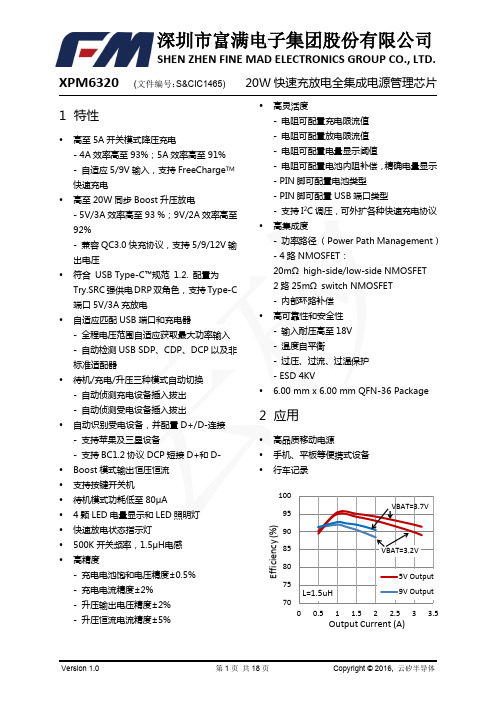
20W 快速充放电全集成电源管理芯片
没有特别注明情况下,以下参数为
,
μΗ 条件下测得。
Parameters
静态电流 Quiescent Currents 待机模式电流 充电模式静态电流 升压模式静态电流 充电系统 Battery Charger VIN 工作电压范围 电池充电饱和电压 电池回充电压阈值 电池回充迟滞电压 电池过压阈值 恒流充电范围
名称 FC NTC ISET OLIM WLED VBUS VIN KEY VOUT VSYS SW NC BOOT VCC VBAT VBATS TCG CC1/CC2 MODE DM/DP LED1~4 RBATC RBATS AGND PGND
描述 升压放电模式工作时,快速放电状态指示 电池温度检测 设置充电电流 设置输出电流 LED 照明灯驱动端口 USB Type-C 接口 VBUS 引脚 输入电源端口 开机使能按键 输出电源端口 系统输出电压 DC-DC 电感接入端 High-side 功率管驱动电源 系统内部电源 电池电压检测端口 电池类型选择端口,悬空 4.2V,接地 4.35V USB Type-C 接口 VBUS 开关管控制端口 USB Type-C 接口 CC 引脚 悬空配置为双 USB-A 接口,接地配置为 USB-A+Type-C 接口 USB 的 D-/D+接入端口,用于 USB 自动识别与快充检测 4 颗 LED 灯驱动端口,用于电池电量显示 电池内阻补偿端口 设置电池电量显示阈值 系统模拟地 系统功率地
UL635H256s2K45中文资料

UL635H256Obsolete - Not Recommended for New DesignsPin ConfigurationPin DescriptionSignal Name Signal Description A0 - A14Address Inputs DQ0 - DQ7Data In/Out E Chip Enable G Output Enable W Write EnableVCC Power Supply Voltage VSSGroundG A11A9A8A13W n. c.VCC n. c.A14A12A7A6A5A4A3n.c.A10E DQ7DQ6DQ5DQ4DQ3VSS DQ2DQ1DQ0A0A1A2n.c.12345678910111213141516TSOPTop View32313029282726252423222120191817A14A12A7A6A5A4A3A2A1A0DQ0DQ1DQ2VSS VCC W A13A8A9A11G A10E DQ7DQ6DQ5DQ4DQ31234567891011121314SOPTop View 2827262524232221201918171615Low Voltage PowerStore 32K x 8 nvSRAM•High-performance CMOS non- volatile static RAM 32768 x 8 bits •35 and 45 ns Access Times •15 and 20 ns Output Enable Access Times•I CC = 8 mA typ. at 200 ns Cycle Time•Automatic STORE to EEPROM on Power Down using system capacitance•Software initiated STORE •Automatic STORE Timing•106 STORE cycles to EEPROM •100 years data retention in EEPROM•Automatic RECALL on Power Up •Software RECALL Initiation •Unlimited RECALL cycles from EEPROM•Wide voltage range: 2.7 ... 3.6 V (3.0 ... 3.6 V for 35 ns type)•Operating temperature range:0 to 70 °C -40 to 85 °C•QS 9000 Quality Standard •ESD protection > 2000 V(MIL STD 883C M3015.7-HBM)•RoHS compliance and Pb- free •Package:SOP28 (330 mil)The UL635H256 has two separate modes of operation: SRAM mode and nonvolatile mode. In SRAM mode, the memory operates as an ordinary static RAM. In nonvolatile operation, data is transferred in parallel from SRAM to EEPROM or from EEPROM to SRAM. In this mode SRAM functions are disab-led.The UL635H256 is a fast static RAM (35 and 45 ns), with a nonvo-latile electrically erasable PROM (EEPROM) element incorporated in each static memory cell. The SRAM can be read and written an unlimited number of times, while independent nonvolatile data resi-des in EEPROM. Data transfers from the SRAM to the EEPROM (the STORE operation) take place automatically upon power down using charge stored in system capacitance. Transfers from the EEPROM to the SRAM (the RECALL operation) take place automatically on powerup.The UL635H256 combines the high performance and ease of use of a fast SRAM with nonvolatile data integrity.STORE cycles also may be initia-ted under user control via a soft-ware sequence.Once a STORE cycle is initiated,further input or output are disabled until the cycle is completed.Because a sequence of addresses is used for STORE initiation, it is important that no other read or write accesses intervene in the sequence or the sequence will be aborted.RECALL cycles may also be initia-ted by a software sequence.Internally, RECALL is a two step procedure. First, the SRAM data is cleared and second, the nonvola-tile information is transferred into the SRAM cells.The RECALL operation in no way alters the data in the EEPROM cells. The nonvolatile data can be recalled an unlimited number of times.FeaturesDescriptionUL635H256EEPROM Array 512 x (64 x 8)RECALLDQ0DQ1DQ2DQ3DQ4DQ5DQ6DQ7Column I/O Column DecoderA0 - A13Store/Recall ControlR o w D e c o d e rV CC V SSGE WA0 A 1 A2 A3 A4A10Software DetectPower ControlV CCA5A6A7A8A9A11A12A13A14I n p u t B u f f e r sSTORESRAM Array 512 Rows x 64 x 8 ColumnsBlock DiagramTruth Table for SRAM OperationsOperating Mode E WGDQ0 - DQ7Standby/not selectedH **High-Z Internal ReadL H H High-Z Read L H LData Outputs Low-Z WriteLL*Data Inputs High-Z*H or LCharacteristicsAll voltages are referenced to V SS = 0 V (ground).All characteristics are valid in the power supply voltage range and in the operating temperature range specified.Dynamic measurements are based on a rise and fall time of ≤ 5 ns, measured between 10 % and 90 % of V I , as well as input levels of V IL = 0 V and V IH = 3 V. The timing reference level of all input and output signals is 1.5 V,with the exception of the t dis -times and t en -times, in which cases transition is measured ± 200 mV from steady-state voltage.a: Stresses greater than those listed under …Absolute Maximum Ratings“ may cause permanent damage to the device. This is a stressrating only, and functional operation of the device at condition above those indicated in the operational sections of this specification is not implied. Exposure to absolute maximum rating conditions for extended periods may affect reliability.Absolute Maximum Ratings a Symbol Min.Max.Unit Power Supply Voltage V CC -0.5 4.6V Input Voltage V I -0.3V CC +0.5V Output Voltage V O -0.3V CC +0.5V Power Dissipation P D 1W Operating Temperature C-Type K-TypeT a 0-407085°C °C Storage TemperatureT stg-65150°CUL635H256b:I CC1 and I CC3 are depedent on output loading and cycle rate. The specified values are obtained with outputs unloaded.The current I CC1 is measured for WRITE/READ - ratio of 1/2.c:I CC2 and I CC4 are the average currents required for the duration of the respective STORE cycles.d:Bringing E ≥ V IH will not produce standby current levels until any nonvolatile cycle in progress has timed out. See MODE SELECTIONtable. The current I CC(SB)1 is measured for WRITE/READ - ratio of 1/2.DC Characteristics Symbol ConditionsC-TypeK-TypeUnitMin.Max.Min.Max.Operating Supply Current bI CC1V CC V IL V IH t c t c= 3.6 V = 0.8 V = 2.2 V = 35 ns = 45 ns 45354737mA mA Average Supply Current during c STOREI CC2V CC E W V IL V IH = 3.6 V ≤ 0.2 V≥ V CC -0.2 V ≤ 0.2 V≥ V CC -0.2 V 34mAOperating Supply Current b at t cR = 200 ns(Cycling CMOS Input Levels)I CC3V CC W V IL V IH = 3.6 V≥ V CC -0.2 V ≤ 0.2 V≥ V CC -0.2 V 1011mAAverage Supply Current during c PowerStore Cycle I CC4V CC V IL V IH = V CCmin = 0.2 V≥ V CC -0.2 V 22mAStandby Supply Current d (Cycling TTL Input Levels)I CC(SB)1V CC E t c t c= 3.6 V = V IH = 35 ns = 45 ns 1191210mA mA Standby Supply Curent d(Stable CMOS Input Levels)I CC(SB)V CC E V IL V IH= 3.6 V≥ V CC -0.2 V ≤ 0.2 V≥ V CC -0.2 V11mARecommendedOperating Conditions Symbol Conditions Min.Max.Unit Power Supply VoltageV CCt c = 35 ns t c = 45 ns3.02.7 3.63.6V V Input Low Voltage V IL -2 V at Pulse Width 10 ns permitted-0.30.8V Input High VoltageV IH2.2V CC +0.3VUL635H256DC Characteristics Symbol ConditionsC-Type K-TypeUnit Min.Max.Min.Max.Output High Voltage Output Low Voltage V OHV OLV CCI OHI OL= V CC min=-2 mA= 2 mA2.40.42.40.4VVOutput High Current Output Low Current I OHI OLV CCV OHV OL= V CC min= 2.4 V= 0.4 V2-22-2mAmAInput Leakage CurrentHigh Low I IHI ILV CCV IHV IL= 3.6 V= 3.6 V=0V-11-11μAμAOutput Leakage CurrentHigh at Three-State- Output Low at Three-State- Output I OHZI OLZV CCV OHV OL= 3.6 V= 3.6 V=0V-11-11μAμASRAM Memory OperationsNo.Switching CharacteristicsRead CycleSymbol3545UnitAlt.IEC Min.Max.Min.Max.1Read Cycle Time f t AVAV t cR3545ns 2Address Access Time to Data Valid g t AVQV t a(A)3545ns 3Chip Enable Access Time to Data Valid t ELQV t a(E)3545ns4Output Enable Access Time to Data Valid t GLQVt a(G)1520ns5 E HIGH to Output in High-Z h t EHQZ t dis(E)1315ns 6G HIGH to Output in High-Z h t GHQZ t dis(G)1315ns 7 E LOW to Output in Low-Z t ELQX t en(E)55ns 8G LOW to Output in Low-Z t GLQX t en(G)00ns 9Output Hold Time after Address Change t AXQX t v(A)33ns 10Chip Enable to Power Active e t ELICCH t PU00ns 11Chip Disable to Power Standby d, e t EHICCL t PD3545ns e:Parameter guaranteed but not tested.f:Device is continuously selected with E and G both Low.g:Address valid prior to or coincident with E transition LOW.h:Measured ± 200 mV from steady state output voltage.UL635H256Read Cycle 1: Ai-controlled (during Read cycle: E = G = V IL , W = V IH )fNo.Switching Characteristics Write Cycle Symbol3545UnitAlt. #1Alt. #2IEC Min.Max.Min.Max.12Write Cycle Time t AVAV t AVAVt cW 3545ns 13Write Pulse Widtht WLWHt w(W)2530ns 14Write Pulse Width Setup Time t WLEHt su(W)2530ns 15Address Setup Time t AVWL t AVEL t su(A)00ns 16Address Valid to End of Write t AVWH t AVEH t su(A-WH)2530ns 17Chip Enable Setup Time t ELWHt su(E)2530ns 18Chip Enable to End of Write t ELEHt w(E)2530ns 19Data Setup Time to End of Write t DVWH t DVEH t su(D)1215ns 20Data Hold Time after End of Write t WHDX t EHDX t h(D)00ns 21Address Hold after End of Write t WHAX t EHAX t h(A)0ns 22W LOW to Output in High-Z h, i t WLQZ t dis(W)1315ns 23W HIGH to Output in Low-Zt WHQXt en(W)55nsRead Cycle 2: G-, E-controlled (during Read cycle: W = V IH )gAi DQiOutputAi E GI CCDQiOutputUL635H256L- to H-level undefined H- to L-leveli:If W is low and when E goes low, the outputs remain in the high impedance state.j:E or W must be V IH during address transition.Write Cycle #1: W-controlled jWrite Cycle #2: E-controlled jAi E W DQiInputDQiOutputHigh ImpedanceAi E W DQiInputDQiOutputUL635H256 Nonvolatile Memory OperationsMode SelectionE W A13 - A0(hex)Mode I/O Power NotesH X X Not Selected Output High Z StandbyL H X Read SRAM Output Data Active m L L X Write SRAM Input Data ActiveL H0E3831C703E03C1F303F0FC0Read SRAMRead SRAMRead SRAMRead SRAMRead SRAMNonvolatile STOREOutput DataOutput DataOutput DataOutput DataOutput DataOutput High ZActive k, lk, lk, lk, lk, lk, lL H0E3831C703E03C1F303F0C63Read SRAMRead SRAMRead SRAMRead SRAMRead SRAMNonvolatile RECALLOutput DataOutput DataOutput DataOutput DataOutput DataOutput High ZActive k, lk, lk, lk, lk, lk, lk:The six consecutive addresses must be in order listed. W must be high during all six consecutive cycles. See STORE cycle and RECALL cycle tables and diagrams for further details.The following six-address sequence is used for testing purposes and should not be used: 0E38, 31C7, 03E0, 3C1F, 303F, 339C.l:While there are 15 addresses on the UL635H256, only the lower 14 are used to control software modes.Activation of nonvolatile cycles does not depend on the state of G.m:I/O state assumes that G ≤ V IL.No.PowerStorePower Up RECALLSymbolConditions Min.Max.UnitAlt.IEC24Power Up RECALL Duration n t RESTORE650μs25STORE Cycle Duration f, e t PDSTORE the power supply decayrate has to be smallerthan 10 Vs-1 after thestart of the STOREoperation10ms26Time allowed to Complete SRAMCycle ft DELAY500ns Low Voltage Trigger Level V SWITCH 2.4 2.7Vn: t RESTORE starts from the time V CC rises above V SWITCH.UL635H256o:The software sequence is clocked with E controlled READs.p:Once the software controlled STORE or RECALL cycle is initiated, it completes automatically, ignoring all inputs.q:Note that STORE cycles (but not RECALL) are aborted by V CC < V SWITCH (STORE inhibit).r: An automatic RECALL also takes place at power up, starting when V CC exceeds V SWITCH and takes t RESTORE . V CC must not drop below V SWITCH once it has been exceeded for the RECALL to function properly.s:Noise on the E pin may trigger multiple READ cycles from the same address and abort the address sequence.t:If the Chip Enable Pulse Width is less than t a(E) (see Read Cycle) but greater than or equal t w(E)SR , than the data may not be valid at the end of the low pulse, however the STORE or RECALL will still be initiated.No.Software Controlled STORE/RECALL Cycle k, o Symbol 3545UnitAlt.IEC Min.Max.Min.Max.27STORE/RECALL Initiation Time t AVAV t cR 3545ns 28Chip Enable to Output Inactive p t ELQZ t dis(E)SR 600600ns 29STORE Cycle Time q t ELQXS t d(E)S 1010ms 30RECALL Cycle Time rt ELQXR t d(E)R 2020μs 31Address Setup to Chip Enable s t AVELN t su(A)SR 00ns 32Chip Enable Pulse Width s, t t ELEHN t w(E)SR 2530ns 33Chip Disable to Address Change st EHAXNt h(A)SRnsPowerStore and automatic Power Up RECALLV CC3.0 VPowerStorePower Up V SWITCH W DQiPOWER UP RECALL BROWN OUT BROWN OUT PowerStore(NO SRAM WRITES)RECALL NO STOREUL635H256Software Controlled STORE/RECALL Cycle t, u, v (E = HIGH after STORE initiation)u:W must be HIGH when E is LOW during the address sequence in order to initiate a nonvolatile cycle. G may be either HIGH or LOWthroughout. Addresses 1 through 6 are found in the mode selection table. Address 6 determines wheter the UL635H256 performs a STORE or RECALL.v: E must be used to clock in the address sequence for the Software controlled STORE and RECALL cycles.Ai EDQiOutputSoftware Controlled STORE/RECALL Cycle t, u, v, w (E = LOW after STORE initiation)Ai EDQiOutputUL635H256Test Configuration for Functional CheckV IHV ILV SS1.1 k95030 pF wV O S i m u l t a n e o u s m e a s u r e -m e n t o f a l l 8 o u t p u t p i n sI n p u t l e v e l a c c o r d i n g t o t h er e l e v a n t t e s t m e a s u r e m e n tDQ0DQ1DQ2DQ3DQ4DQ5DQ6DQ7A0A1A2A3A4A5A6A7A8A9A10A11A12E W G3 VA13A14V CCXw:In measurement of t dis -times and t en -times the capacitance is 5 pF.x:Between V CC and V SS must be connected a high frequency bypass capacitor 0.1 μF to avoid disturbances.Capacitance e Conditions Symbol Min.Max.Unit Input Capacitance V CC V I f T a= 3.0 V = V SS = 1MHz = 25 °CC I 8pF Output CapacitanceC O7pFAll Pins not under test must be connected with ground by capacitors.Operating Temperature Range C =0to 70 °C K =-40to 85 °CG1S245C UL635H256TypePackageS =SOP28 (330mil) Type 1 S2 = SOP28 (330mil) Type 2Ordering Code Leadfree Optionblank =Standard PackageG1=Leadfree Green Package Access Time35=35 ns (V CC = 3.0 ... 3.6 V)45=45 ns (V CC = 2.7 ... 3.6 V)y: on special requestExample Date of manufacture(The first 2 digits indicating the year, and the last 2 digits the calendar week.)Leadfree Green PackageProduct specificationInternal CodeDevice Marking (example)ZMDUL635H256S2C 45Z 0425G1UL635H25611March 31, 2006STK Control #ML0059Rev 1.0Device OperationThe UL635H256 has two separate modes of operation:SRAM mode and nonvolatile mode. The memory ope-rates in SRAM mode as a standard fast static RAM.Data is transferred in nonvolatile mode from SRAM to EEPROM (the STORE operation) or from EEPROM to SRAM (the RECALL operation). In this mode SRAM functions are disabled.STORE cycles may be initiated under user control via a software sequence and are also automatically initiated when the power supply voltage level of the chip falls below V SWITCH . RECALL operations are automatically initiated upon power up and may also occur when the V CC rises above V SWITCH , after a low power condition.RECALL cycles may also be initiated by a software sequence.SRAM READThe UL635H256 performs a READ cycle whenever E and G are LOW and W is HIGH. The address specified on pins A0 - A14 determines which of the 32768 data bytes will be accessed. When the READ is initiated by an address transition, the outputs will be valid after a delay of t cR . If the READ is initiated by E or G, the out-puts will be valid at t a(E) or at t a(G), whichever is later.The data outputs will repeatedly respond to address changes within the t cR access time without the need for transition on any control input pins, and will remain valid until another address change or until E or G is brought HIGH or W is brought LOW.SRAM WRITEA WRITE cycle is performed whenever E and W are LOW. The address inputs must be stable prior to entering the WRITE cycle and must remain stable until either E or W goes HIGH at the end of the cycle. The data on pins DQ0 - 7 will be written into the memory if it is valid t su(D) before the end of a W controlled WRITE or t su(D) before the end of an E controlled WRITE.It is recommended that G is kept HIGH during the entire WRITE cycle to avoid data bus contention on the common I/O lines. If G is left LOW, internal circuitry will turn off the output buffers t dis (W) after W goes LOW.Automatic STOREThe UL635H256 uses the intrinsic system capacitance to perform an automatic STORE on power down. As long as the decay rate from the system power supply is smaller than 15 Vs -1 the UL635H256 will safely and automatically STORE the SRAM data in EEPROM on power down.In order to prevent unneeded STORE operations, auto-matic STORE will be ignored unless at least one WRITE operation has taken place since the most recent STORE or RECALL cycle. Software initiated STORE cycles are performed regardless of whether or not a WRITE operation has taken place.Automatic RECALLDuring power up, an automatic RECALL takes place. At a low power condition (power supply voltage < V SWITCH )an internal RECALL request may be latched. As soon as power supply voltage exceeds the sense voltage of V SWITCH , a requested RECALL cycle will automatically be initiated and will take t RESTORE to complete.If the UL635H256 is in a WRITE state at the end of power up RECALL, the SRAM data will be corrupted. To help avoid this situation, a 10 k Ω resistor should be connected between W and power supply voltage.Software Nonvolatile STOREThe UL635H256 software controlled STORE cycle is initiated by executing sequential READ cycles from six specific address locations. By relying on READ cycles only, the UL635H256 implements nonvolatile operation while remaining compatible with standard 32K x 8SRAMs. During the STORE cycle, an erase of the pre-vious nonvolatile data is performed first, followed by a parallel programming of all the nonvolatile elements.Once a STORE cycle is initiated, further inputs and out-puts are disabled until the cycle is completed.Because a sequence of addresses is used for STORE initiation, it is important that no other READ or WRITE accesses intervene in the sequence or the sequence will be aborted.To initiate the STORE cycle the following READ sequence must be performed:1. Read addresses 0E38(hex)Valid READ 2. Read addresses 31C7(hex)Valid READ 3. Read addresses 03E0(hex)Valid READ 4. Read addresses 3C1F (hex)Valid READ 5. Read addresses 303F (hex)Valid READ 6.Read addresses0FC0(hex)Initiate STORE CycleOnce the sixth address in the sequence has been entered, the STORE cycle will commence and the chip will be disabled. It is important that READ cycles and not WRITE cycles be used in the sequence, although it is not necessary that G be LOW for the sequence to be valid. After the t STORE cycle time has been fulfilled, the SRAM will again be activated for READ and WRITE operation.UL635H25612 March 31, 2006STK Control #ML0059Rev 1.0Software Nonvolatile RECALLA RECALL cycle of the EEPROM data into the SRAMis initiated with a sequence of READ operations in amanner similar to the STORE initiation. To initiate theRECALL cycle the following sequence of READ opera-tions must be performed:1. Read addresses0E38(hex)Valid READ2. Read addresses31C7(hex)Valid READ3. Read addresses03E0(hex)Valid READ4. Read addresses3C1F(hex)Valid READ5. Read addresses303F(hex)Valid READ6. Read addresses0C63(hex)Initiate RECALLCycleInternally, RECALL is a two step procedure. First, theSRAM data is cleared and second, the nonvolatileinformation is transferred into the SRAM cells. Aftert d(E)R cycle time the SRAM will once again be ready forREAD and WRITE operations.The RECALL operationin no way alters the data in the EEPROM cells. Thenonvolatile data can be recalled an unlimited number oftimes.Hardware ProtectionThe UL635H256 offers hardware protection againstinadvertent STORE operation through V CC Sense.When V CC < V SWITCH all software STORE operationswill be inhibited.Low Average Active PowerThe UL635H256 has been designed to draw signifi-cantly less power when E is LOW (chip enabled) butthe cycle time is longer than 45 ns.When E is HIGH the chip consumes only standby cur-rent.The overall average current drawn by the part dependson the following items:1. CMOS or TTL input levels2. the time during which the chip is disabled (E HIGH)3. the cycle time for accesses (E LOW)4. the ratio of READs to WRITEs5. the operating temperature6. the V CC levelThe information describes the type of component and shall not be considered as assured characteristics. Terms of delivery and rights to change design reserved.UL635H256LIFE SUPPORT POLICYSimtek products are not designed, intended, or authorized for use as components in systems intended for surgical implant into the body, or other applications intended to support or sustain life, or for any other application in which the failure of the Simtek product could create a situation where personal injury or death may occur.Components used in life-support devices or systems must be expressly authorized by Simtek for such purpose. LIMITED WARRANTYThe information in this document has been carefully checked and is believed to be reliable. However, Simtek makes no guarantee or warranty concerning the accuracy of said information and shall not be responsible for any loss or damage of whatever nature resulting from the use of, or reliance upon it. The information in this document describes the type of component and shall not be considered as assured characteristics.Simtek does not guarantee that the use of any information contained herein will not infringe upon the patent, trademark, copyright, mask work right or other rights of third parties, and no patent or licence is implied hereby. This document does not in any way extent Simtek’s warranty on any product beyond that set forth in its standard terms and conditions of sale.Simtek reserves terms of delivery and reserves the right to make changes in the products or specifications, or both, presented in this publication at any time and without notice.March 31, 2006Change recordDate/Rev Name Change01.11.2001Ivonne Steffens format revision and release for …Memory CD 2002“03.07.2002Matthias Schniebel adding 35 ns type with V CC = 3.0 ... 3.6 V25.09.2002Matthias Schniebel Adding …Type 1“ to SOP28 (330mil)09.01.2003Matthias Schniebel Removing 55 ns type20.10.2003Matthias Schniebel Low Voltage Trigger Level V SWITCH = 2.4 ... 2.7 V (old: 2.5 ... 2.7 V)changing max. decay rate from the system power supply to 15 Vs-1(old: 10 Vs-1)05.12.2003Matthias Schniebel I CC = 8 mA typ. at 200 ns Cycle Timeadding K-Type with 35 ns: I CC1 = 47 mA, I CC(SB)1 = 12mA21.04.2004Matthias Schniebel adding …Leadfree Green Package“ to ordering informationadding …Device Marking“7.4.2005Stefan Günther Page1: adding RoHS compliance and Pb- free, 106 endurance cyclesand 100a data retention,add also S2 package (chip pack) and ordering code31.3.2006Troy Meester changed to obsolete status1.0Simtek Assigned Simtek Document Control Number。
EM6323LXSP5B2.6中文资料

元器件交易网EM MICROELECTRONIC - MARIN SAEM6323/24Reset Circuit with Manual Reset and WatchdogDescriptionThe EM6323/24 are low power, high precision reset ICs featuring a manual reset and a watchdog inputs. They have different threshold voltages and several timeout reset periods (tPOR) and watchdog timeout periods (tWD) for maximum flexibility in the application. EM6323 has a manual reset ( MR with internal pull-up) and a watchdog input pins. EM6324 has only a watchdog input pin (WDI). The watchdog function can be disabled by driving WDI with a three-state driver or by leaving WDI unconnected. This is useful when the MCU is in sleep mode. Small SOT23-5L package as well as ultra-low supply current of 3.8µA make the EM6323 and the EM6324 an ideal choice for portable and battery-operated devices.Features! ! ! ! ! ! !Ultra-low supply current of 3.8µA (VDD=3.3V) Operating temperature range: -40°C to +125°C ±1.5% reset threshold accuracy 11 reset threshold voltages VTH: 4.63V, 4.4V, 3.08V, 2.93V, 2.63V, 2.2V, 1.8V, 1.66V, 1.57V, 1.38V, 1.31V 200ms reset timeout period (1.6ms, 25ms, 1600ms on request) 1.6s watchdog timeout period (6.2ms, 102ms, 25.6s on request) 3 reset output options: Active-low RESET push-pull Active-low RESET open-drain Active-high RESET push-pull Detection of microcontroller in sleep modeTypical ApplicationVDDVDD RESET RESET*VDD RESET RESET!Applications! ! ! ! ! ! !EM632xMR GND WDIMPU, DSPI/O GNDGND * REXT for open-drain version onlyFig. 1Block DiagramVDDOscillatorWorkstations Point of sales (POS) Personal computers Routers, hubs and switches Handheld GPS Vending machines and ATM Automotive systemsPin ConfigurationRESET RESET+Voltage Reference-Reset Logic + TimerEM6323RESET GND MR 1 2 3(manual reset, watchdog)5 VDDEM6324push-pull/open-drain(watchdog)5 VDDRESET GNDEM6323MR GND WDITransition DetectorFilter2 3EM632414WDIRESETpush-pull4WDIWatchdog Logic + TimerSOT23-5Fig. 2top viewSOT23-5top viewFig. 3Pin DescriptionSOT23-5L EM6323 EM6324 1 2 3 4 5 1 2 3 4 5 NameRESETFunction Active-low RESET output (push-pull or open-drain) Ground Manual Reset input with an internal pull-up 30kΩ resistor. Reset remains active as long as MR is low and for tPOR after returns high. MR can be driven with a CMOS output or shorted to ground with a switch Active-high RESET output (push-pull) Watchdog input. WDI must be driven with a CMOS output. If the microcontroller I/O is put in a high impedance condition, the circuit will detect this condition as a microcontroller in sleep mode and prevent its watchdog from timing out Supply Voltage (5.5V max.)GNDMRRESET WDI VDDCopyright © 2006, EM Microelectronic-Marin SA 03/06 - rev.H1元器件交易网EM6323/24Ordering InformationEM6323 L X SP5B - 2.9 +Part Number: EM6323 = manual reset & watchdog EM6324 = watchdog Delays tPOR & tWD : tPOR [ms] EM6323/24: 1.6 25 200 1600 6.2 A B C D 102 E F G H 1600 J K L M 25600 N P Q R ("L" is the standard version") tWD [ms] RoHS Compliance: + = lead-free/green mold compliant [blank] = leaded Reset Threshold Voltage: 1.3 = 1.31V 1.4 = 1.38V 1.6 = 1.57V 1.7 = 1.66V 1.8 = 1.80V 2.2 = 2.20V 2.6 = 2.63V 2.9 = 2.93V 3.1 = 3.08V 4.4 = 4.40V 4.6 = 4.63VPackage: SP5B = 5-pin SOT23-5, tape&reel, 3000 pcsReset Output Type: X = Active-low /RESET push-pull (Active-high RESET push-pull also for EM6324) Y = Active-low /RESET open-drain (Active-high RESET push-pull also for EM6324) Z = Active-high RESET push-pull (EM6323 only)Note:subject to availability (see standard versions list below). Please give complete Part Number when orderingStandard Versions (Top Marking)Threshold Voltage 2.6V 2.63V 2.63V 2.93V 2.93V 3.08V 2.93V 2.93V 3.1V 3.1V 4.40V 4.40V 2.9V 1.38V1) 2)Delay (tPOR)/ Watchdog timer (tWD) 200ms/1600ms 200ms/1600ms 200ms/1600ms 200ms/1600ms 200ms/1600ms 200ms/1600ms 200ms/1600ms 200ms/1600ms 200ms/1600ms 200ms/1600ms 200ms/1600ms 200ms/1600ms 200ms/1600ms 200ms/25600msOutput Type Active-high push-pull RESET Active-low push-pull RESET Active-low push-pull RESET Active-low push-pull RESET Active-low push-pull RESET Active-low push-pull RESET Active-low open-drain RESET Active-low open-drain RESET Active-low open-drain RESET Active-low push-pull RESET Active-low push-pull RESET Active-low push-pull RESET Active-low open-drain RESET Active-low push-pull RESETPackage SOT23-5L SOT23-5L SOT23-5L SOT23-5L SOT23-5L SOT23-5L SOT23-5L SOT23-5L SOT23-5L SOT23-5L SOT23-5L SOT23-5L SOT23-5L SOT23-5LPart Number EM6323LZSP5B-2.6 EM6323LXSP5B-2.6 EM6323LXSP5B-2.6+ EM6323LXSP5B-2.9 EM6323LXSP5B-2.9+ EM6323LXSP5B-3.1 EM6323LYSP5B-2.9 EM6323LYSP5B-2.9+ EM6323LYSP5B-3.1 EM6323LXSP5B-3.1 EM6324LXSP5B-4.4 EM6324LXSP5B-4.4+ EM6324LYSP5B-2.9 EM6324QXSP5B-1.4Top Top Marking 1) with 4 Marking 2) characters APL5 APLG KF## BPLG APLH K0## BPLH APLJ APLU K6## BPLU APLV APLJ AQMK K9## BQMK AQLU AQQBTop marking is standard from 2006. No bottom marking exists. Where ## refers to the lot number (EM internal reference only) Top marking with 4 characters is standard from 2003. For lead-free/green mold (RoHS) parts, the first letter of top marking with 4 characters begins with letter “B” instead of letter “A”. Bottom marking indicates the lot number.Standard Versions (samples)Part Number EM6323LXSP5B-2.6+ EM6323LXSP5B-2.9+ Part Number EM6323LYSP5B-2.9+ EM6324LXSP5B-4.4+Sample stock is generally held on standard versions only. Non standard versions have a 30,000 pieces minimum order quantity. Please contact factory for other versions not shown here and for availability of non standard versions.Copyright © 2006, EM Microelectronic-Marin SA 03/06 - rev.H 2 元器件交易网EM6323/24Absolute Maximum RatingsParameterVoltage at VDD to GND Minimum voltage at any signal pin Maximum voltage at any signal pinHandling ProceduresSymbolVDD VMIN VMAX VESD TMAX TSTGConditions-0.3V to +6V GND - 0.3V VDD + 0.3V 2000V 250°C x 10s -65°C to +150°CElectrostatic discharge max. to MIL-STD-883C method 3015.7 with ref. to VSSMax. soldering conditions Storage Temperature RangeThis device has built-in protection against high static voltages or electric fields; however, anti-static precautions must be taken as for any other CMOS component. Unless otherwise specified, proper operation can only occur when all terminal voltages are kept within the voltage range. Unused inputs must always be tied to a defined logic voltage level.Operating ConditionsParameterSupply voltage Operating Temperature Input transition rise and fall rate on MR and WDIStresses above these listed maximum ratings may cause permanent damages to the device. Exposure beyond specified operating conditions may affect device reliability or cause malfunction.Symbol Min Max UnitVDD TA tR/tF 0.9 5.5 V -40 +125 °C 100 ns/VElectrical CharacteristicsUnless otherwise specified: VDD= 0.9V to 5.5V, TA=-40°C to +125°C (note 1). Parameter Symbol ConditionsVDD=1.5V Supply current (note 2) IDD VDD=3.3V VDD=5.0V EM6323/24 – 1.3 +25°C -40°C to +125°C +25°C -40°C to +125°C +25°C -40°C to +125°C +25°C -40°C to +85°C -40°C to +125°C +25°C -40°C to +85°C -40°C to +125°C +25°C -40°C to +85°C -40°C to +125°C +25°C -40°C to +85°C -40°C to +125°C +25°C -40°C to +85°C -40°C to +125°C +25°C -40°C to +85°C -40°C to +125°C +25°C -40°C to +85°C -40°C to +125°C +25°C -40°C to +85°C -40°C to +125°C +25°C -40°C to +85°C -40°C to +125°C +25°C -40°C to +85°C -40°C to +125°C +25°C -40°C to +85°C -40°C to +125°CMin1.290 1.245 1.221 1.359 1.311 1.286 1.546 1.492 1.463 1.635 1.577 1.547 1.773 1.710 1.678 2.167 2.090 2.050 2.591 2.499 2.451 2.886 2.784 2.731 3.034 2.926 2.871 4.334 4.180 4.101 4.561 4.399 4.315Typ2.4 3.86 5.89 1.31Max4.4 6.8 6.1 9.9 8.6 11.6 1.330 1.382 1.387 1.401 1.456 1.461 1.594 1.656 1.663 1.685 1.751 1.758 1.827 1.899 1.906 2.233 2.321 2.330 2.669 2.775 2.785 2.974 3.091 3.103 3.126 3.249 3.262 4.466 4.642 4.660 4.699 4.885 4.903UnitµAEM6323/24 – 1.41.38EM6323/24 – 1.61.57EM6323/24 – 1.71.66EM6323/24 – 1.8 Threshold voltage (note 3)1.80VTHEM6323/24 – 2.22.20VEM6323/24 – 2.62.63EM6323/24 – 2.92.93EM6323/24 – 3.13.08EM6323/24 – 4.44.40EM6323/24 – 4.64.63Note 1: Production tested at +25°C only. Over temperature limits are guaranteed by design, not production tested. Note 3: Threshold voltage is specified for VDD falling.Copyright © 2006, EM Microelectronic-Marin SA 03/06 - rev.H3元器件交易网EM6323/24Electrical Characteristics(continued)Unless otherwise specified: VDD= 0.9V to 5.5V, TA=-40°C to +125° C (note 1).ParameterThreshold hysteresisSymbolVHYSConditionsTA=+25°C EM6323/24 C-G-L-Q VDD from 0V to VTH (typ)+15% TA= +25°C (note 2 and 4) EM6323/24 A-E-J-N EM6323/24 B-F-K-P EM6323/24 D-H-M-RMin160 0.7 20 12802 0.8 2 4 -Typ2.1%•VTH 200 1.56 25 160070 1600 6.25 100 25600 18 8.3 0.3 30Max240 3.8 30 1920255 0.3 0.3 0.35 0.3 0.3 0.35 0.5 0.3•VDD 1920 7.5 120 30720 0.3•VDD 74UnitVReset timeout periodtPORmsPropagation delay time VDD to RESET (RESET) delayOpen-drain RESET output Voltage tPVDD drops from VTH (typ)+0.2V to VTH (typ)-0.2V (note 2). TA= +25°C VDD>1V IOL=100µA IOL=1.5mA IOL=3mA IOL=100µA IOL=1.5mA IOL=3mA IOH=-30µA IOH=-1.5mA IOH=-3mAµsVOLVDD>2.5V VDD>5V VDD>1VVVOL Push-pull RESET / RESET Output voltage VOH Output leakage current ILEAK VWDI low VWDI high tWPVDD>2.5V VDD>5V VDD>1.1V VDD>2.5V VDD>5VVOnly for EM6323/24_Y (open-drain)µAV VWATCHDOG INPUT (WDI)WDI Input low WDI Input high Pulse width at WDI TA= +25°C EM6323/24 J-K-L-M Watchdog timeout period tWD (note 6) EM6323/24 A-B-C-D EM6323/24 E-F-G-H EM6323/24 N-P-Q-R High-level Input Current Low-level Input Current IIH IIL VMRT low VMRT high tMD tPMD RMR TA=-40°C to +125°C TA= +25°C WDI connected to VDD, TA= +25°C WDI connected to GND, TA= +25°C 0.7•VDD 1 1280 5 80 20480 0.7•VDD 1 7µsmsµA µAV VMANUAL RESET ( MR ) – EM6323 onlyMR Input low MR Input high MR to Reset delayPulse width at MR (note 5)µs µskΩMR Internal Pull-up resistorProduction tested at +25°C only. Over temperature limits are guaranteed by design, not production tested. WDI, MR and RESET (RESET) open. Threshold voltage is specified for VDD falling. Standard version for tPOR is 200ms (typ). Other option (1.6ms, 25ms, 1600ms) are available by mask option and upon minimum order quantity. Please contact EM sales. Note 5: Pulse width must be greater than 1µs to ensure the RESET (RESET) to go active. Note 6: Standard version for tWD is 1600ms (typ). Other option (6.2ms, 102ms, 25.6s) are available by mask option and upon minimum order quantity. Please contact EM sales.Note 1: Note 2: Note 3: Note 4:Copyright © 2006, EM Microelectronic-Marin SA 03/06 - rev.H4元器件交易网EM6323/24Timing WaveformsVDD VTHtSEN VHYS Overdrive0.9V t logic "1" MR logic "0" t logic "1" RESET logic "0" t logic "1" RESET logic "0" tFig. 4tPMDtPORtMDtPtPORlogic "1" WDI logic "0"tWP tWD tWDt logic "1" RESET logic "0" t logic "1" RESET logic "0" tFig. 5tPORNote 7: tSEN = Maximum Transient Duration. Please refer to figure on the next page. Note 8: Overdrive = VTH -VDD. Please refer to figure on the next page.Copyright © 2006, EM Microelectronic-Marin SA 03/06 - rev.H5元器件交易网EM6323/24Typical Operating Characteristics(Typical values are at TA=+25°C unless otherwise noted. WDI, MR , RESET and RESET open.)9 8 7 6 5 [ uA ] 4 3 2 1 0 -50 -25 0 25 50 [ °C ] 75 100 125VDD 3 . 3 V VDD 5 . 0 V6% 4% 2% 0% -2%VDD 1. 5 V-4% -6% -50 -25 0 25 50 [ °C ] 75 100 125Fig. 6Fig. 7IDD vs. TemperatureThreshold Voltage Variation vs. Temperature (normalized)160% 140% 120% 100% 80% 60% -50 -25 0 25 50 [ °C ] 75 100 125Fig. 8160%tPOR (°C) tPOR (25°C)140% 120% 100% 80% 60% -50 -25 0 25 50 [ °C ]tWD (°C) tWD (25°C)75100125Fig. 9Reset Timeout Period tPOR vs. Temperature (normalized with respect to tPOR 25°C)Watchdog Timeout Period tWD vs. Temperature (normalized with respect to tWD 25°C)Copyright © 2006, EM Microelectronic-Marin SA 03/06 - rev.H6元器件交易网EM6323/24Typical Operating Characteristics(Typical values are at TA=+25°C unless otherwise noted. WDI, MR , RESET and RESET open.)120 100 80 [ us ] 60 40 20 0 -50 120 100 80 [ us ] 60 40 20 0 -25 0 25 50 [ °C ] 75 100 125Fig. 10Reset occurs above this line110[ mV ]1001000Fig. 11Propagation Time tPHL vs. TemperatureMaximum Transient Duration tSEN vs. Overdrive VTH-VD250 225 200[ ns ]350 300 250 [ ns ] 200 150 100 -50175 150 125 100 -50 -25 0 25[ °C ]5075100 125Fig. 12-25025 50 [ °C ]75100125Watchdog Input Pulse Width tWP vs. TemperatureFig. 13Manual Reset Pulse Width tPMD vs. TemperatureCopyright © 2006, EM Microelectronic-Marin SA 03/06 - rev.H7元器件交易网EM6323/24Functional DescriptionVDD MR WDIHigh ImpedanceRESET t < tWD tPOR t > tWD tPOR tPORFig. 14Reset OutputsA microprocessor (µP) reset input starts the µP in a known state. The EM6323/24 µP supervisory circuits assert a reset to prevent code-execution errors during power-up, power-down, and brownout conditions. RESET is guaranteed to be a logic low for VDD down to 0.9V. Once VDD exceeds the reset threshold, an internal timer keeps RESET low for the specified reset timeout period (tPOR); after this interval, RESET returns high. If a brownout condition occurs (VDD dips below the reset threshold), RESET goes low. Each time RESET is asserted it stays low for the reset timeout period. Any time VDD goes below the reset threshold the internal timer restarts. RESET is the inverse of RESET.Manual Reset Input (EM6323 only)A logic low on MR asserts a reset. Reset remains asserted while MR is low, and for tPOR (200ms nominal for EM6323 C-G-L-Q) after it returns high. MR has an internal 30kΩ pull-up resistor, so it can be left open if unused. This input can be driven with CMOS logic levels or with open-drain outputs. Connect a normally open momentary switch from MR to VSS to create a manualreset function; debounce circuitry is integrated. If MR is driven from long cable or the device is used in a noisy environment, connect a 0.1µF capacitor from MR to VSS to provide additional noise immunity (stronger external additional pull-up resistor can also be added).Copyright © 2006, EM Microelectronic-Marin SA 03/06 - rev.H8元器件交易网EM6323/24Watchdog InputIf the watchdog timer has not been cleared within tWD (1.6s typ.), reset asserts. The internal 1.6s timer is cleared by either a reset pulse or by toggling WDI. While reset is asserted, the timer remains cleared and does not count. As soon as reset is released, the timer starts counting. If the microcontroller I/O connected to WDI is put in a high impedance condition, the circuit will detect this condition as a microcontroller in sleep mode and prevent its watchdog from timing out. To monitor a high impedance or a three state condition on WDI, the watchdog input is internally driven low during the first 15/16 of the watchdog timeout period and high for the last 1/16 of the watchdog timeout period. When WDI is left unconnected, this internal driver clears the 1.6s timer every 1.5s. When WDI is three-stated or unconnected, the maximum allowable leakage current is 0.5µA. To minimized the overall system power consumption and therefore for a minimum watchdog input current leave WDI low for the majority of the watchdog timeout period, pulsing it low-high-low once within the first 15/16 of the watchdog timeout period to reset the watchdog timer. If WDI is externally driven high for the majority of the timeout period, up to 35µA can flow into WDI. Meanwhile when the microcontroller is not in sleep mode, the output of the microcontroller which drives WDI has to be strong enough to fight the 35µA.VDDVDD RESET1/16 tWDPullupWDI Pullup OFFONOFFWDI15/16 tWDTransition DetectorWatchdog Logic + TimerWDI Pulldown ONOFFONtPOR15/16 tWD tWD1/16 tWDGNDPulldownFig. 15Fig. 16WDI Input Timing DiagramWDI Input Stage Block Schematic15.0 12.0 9.0 [ uA ] 6.0 3.0 0.0 -5025.0 20.0 15.0[ uA ]10.0 5.0 0.0-25 0 25 50 75 100 125-50-250255075100 125[ °C ]Fig. 17[ °C ]Fig. 18WDI Input Current Low-level IIL vs. Temperature (VDD=5.5V)WDI Input Current High-Level IIH vs. Temperature (VDD=5.5V)Copyright © 2006, EM Microelectronic-Marin SA 03/06 - rev.H9元器件交易网EM6323/24Package InformationDA1 A2 ASOT23-5LE1C Lb eSYM BOL A A1 A2 b C D E E1 e e1 LEM IN 0.90 0.05 0.90 0.35 0.08 2.80 2.60 1.50e1TYP M AX 1.30 1.45 0.08 0.15 1.15 1.30 0.50 0.20 2.90 3.00 2.80 3.00 1.75 0.95 1.90 0.45Dimensions are in mmFig. 19Traceability for small packagesDue to the limited space on the package surface, the bottom marking contains a limited number of characters that provide only partial information for lot traceability. Full information for complete traceability is however provided on the packing labels of the product at delivery from EM. It is highly recommended that the customer insures full lot traceability of EM product in his final product.EM Microelectronic-Marin SA (EM) makes no warranty for the use of its products, other than those expressly contained in the Company's standard warranty which is detailed in EM's General Terms of Sale located on the Company's web site. EM assumes no responsibility for any errors which may appear in this document, reserves the right to change devices or specifications detailed herein at any time without notice, and does not make any commitment to update the information contained herein. No licenses to patents or other intellectual property of EM are granted in connection with the sale of EM products, expressly or by implications. EM's products are not authorized for use as components in life support devices or systems.Product qualification is performed according to internal EM quality standards for industrial products. For any special requirement (eg. automotive grade) please contact EM Microelectronic-Marin S.A.Copyright © 2006, EM Microelectronic-Marin SA 03/06 - rev.H10。
W25Q64中文资料精编版
W25Q64BV出版日期:2010年7月8日- 1 - 版本E64M位与串行闪存双路和四路SPIW25Q64BV- 2 -目录1,一般DESCRIPTION (5)2。
FEATURES (5)3引脚配置SOIC208-MIL.......................................... .. (6)4,焊垫配置WSON8X6-MM.......................................... . (6)5,焊垫配置PDIP300-MIL.......................................... . (7)6引脚说明SOIC208密耳,PDIP300密耳和WSON8X6-MM................................ 7......7引脚配置SOIC300mil的.......................................... .. (8)8引脚SOIC封装说明300-MIL (8)8.1包装Types (9)8.2片选(/CS) (9)8.3串行数据输入,输出和IO(DI,DO和IO0,IO1,IO2,IO3)............................. 9.......8.4写保护(/WP) (9)8.5控股(/HOLD) (9)8.6串行时钟(CLK) (9)9座DIAGRAM (10)10功能DESCRIPTION (11)10.1 SPI OPERATIONS (11)10.1.1标准SPI Instructions (11)10.1.2双SPI Instructions (11)10.1.3四路SPI Instructions (11)10.1.4保持功能 (11)10.2写保护 (12)10.2.1写保护Features (12)11,控制和状态寄存器............................................ .. (13)11.1状态REGISTER (13)11.1.1 BUSY (13)11.1.2写使能锁存(WEL) (13)11.1.3块保护位(BP2,BP1,BP0)..................................... .. (13)11.1.4顶/底块保护(TB)....................................... .................................................. ..1311.1.5部门/块保护(SEC) (13)11.1.6状态寄存器保护(SRP,SRP0)....................................... . (14)11.1.7四路启用(QE) (14)11.1.8状态寄存器内存保护........................................... .. (16)11.2 INSTRUCTIONS (17)11.2.1制造商和设备标识........................................... .. (17)11.2.2指令集表1 (18)W25Q64BV11.2.3指令表2(阅读说明书)....................................... (19)出版日期:2010年7月8日- 3 - 修订版E11.2.4写使能(06h) (20)11.2.5写禁止(04h) (20)11.2.6读状态寄存器1(05H)和读状态寄存器2(35H).............................. (21)11.2.7写状态寄存器(01H)......................................... .................................................. .. (22)11.2.8读取数据(03h) (23)11.2.9快速阅读(0Bh) (24)11.2.10快速读双输出(3BH)........................................ .................................................. 0.25 11.2.11快速读四路输出(6BH)........................................ .. (26)11.2.12快速读双I / O (BBh) (27)11.2.13快速读取四I/ O (EBh) (29)11.2.14八进制字读取四I/ O(E3H)..................................... (31)11.2.15页编程(02h) (33)11.2.16四路输入页编程(32H)........................................ . (34)11.2.17扇区擦除(20H) (35)11.2.1832KB的块擦除(52H) (36)11.2.1964KB的块擦除(D8h) (37)20年2月11日芯片擦除(C7H/ 60h) (38)21年2月11日擦除挂起(75h) (39)22年2月11日擦除恢复(7Ah) (40)23年11月2日掉电(B9h) (41)24年2月11日高性能模式(A3H)......................................... (42)25年2月11日发布掉电或高性能模式/设备ID(ABH) (42)26年2月11日读制造商/设备ID(90H)....................................... . (44)27年2月11日阅读唯一的ID号(4BH)........................................ . (45)28年2月11日读JEDEC的ID (9Fh) (46)29年2月11日连续读取模式复位(FFH或FFFFH)...................................... .. (47)12,电气特性.............................................. (48)12.1绝对最大Ratings (48)12.2操作范围 (48)12.3上电时序和写抑制阈值......................................... (49)12.4直流电气Characteristics (50)12.5 AC测量条件.............................................. .. (51)12.6 AC电气Characteristics (52)12.7 AC电气特性(续)......................................... . (53)12.8串行输出Timing (54)12.9输入Timing (54)12.10持有Timing (54)13包装SPECIFICATION (55)W25Q64BV13.18引脚SOIC208密耳(包装代号SS)..................................... .. (55)- 4 -13.28引脚PDIP300密耳(封装代码DA)..................................... (56)13.38触点WSON8x6毫米(封装代码ZE)....................................... (57)13.416引脚SOIC300密耳(封装代码SF)..................................... . (58)14订货INFORMA TION (59)14.1有效的部件号和顶端标记.......................................... (60)15版本HISTORY (61)W25Q64BV出版日期:2010年7月8日- 5 - 修订版E1概述该W25Q64BV(64M位)串行Flash存储器提供了有限的系统存储解决方案空间,引脚和电源。
MAX6352MRUK-T中文资料

Features
o Precision Monitoring of Multiple +2.5V, +3.0V, +3.3V, and +5V Power-Supply Voltages o Precision Factory-Set Power-Supply Reset Thresholds o 20µA Supply Current o 100ms min Power-On Reset Pulse Width o Fully Guaranteed Over Temperature o Guaranteed RESET Valid to VCC5 = 1V or VCC3 = 1V o Power-Supply Transient Immunity o No External Components for Dual-Voltage Systems o Small 5- and 6-Pin SOT23 Packages o Debounced TTL/CMOS-Compatible Manual-Reset Input o Watchdog Timer 46.4sec Start-Up Timeout 2.9sec Normal Timeout o Low Cost
Dual/Triple-Voltage µP Supervisory Circuits MAX6351–MAX6360
ABSOLUTE MAXIMUM RATINGS
VCC5, VCC3 to GND .................................................-0.3V to +6V RST (MAX6352/55/58) ............................................. -0.3V to +6V RST, MR, WDI, RST5, RSTIN (MAX6351/53/56/59).............................-0.3V to (VCC5 + 0.3V) RST, RST3 (MAX6351/54/57/60) .................-3V to (VCC3 + 0.3V) Input/Output Current, All Pins .............................................20mA Continuous Power Dissipation (TA = +70°C) 5-Pin SOT23-5 (derate 7.1mW/°C above +70°C) ........571mW 6-Pin SOT23-6 (derate 7.1mW/°C above +70°C) ........571mW Operating Temperature Range ...........................-40°C to +85°C Storage Temperature Range .............................-65°C to +150°C Lead Temperature (soldering, 10sec) .............................+300°C
EM6322FP8CT-85S中文资料(Emerging Memory)中文数据手册「EasyDatasheet - 矽搜」

推荐直流工作条件
1)
参数 电源电压 地面 输入高电压
输入低电压
符号
VCC VSS VIH VIL
Min 2.7 0 2.2 -0.2 3)
Typ
Max
Unit
3.3
3.6
V
0
0
V
-
VCC + 0.2 2)
V
-
0.6
V
1. TA = -40到85 oC,另有说明
2. 过冲:V
符号
VIN , V OUT VCC PD TA
* 强调超过"绝对最大额定值"可能会造成永久性损坏设备.功能 操作应仅限于推荐工作条件.暴露在绝对最大额定值条件下长时间可能会影响其可靠性.
EM641FV8FS系列
低功耗,512Kx8 SRAM
额定值
-0.2 to Vcc+0.3(Max.4.0V) -0.2 to 4.0V 1.0 -40到85
芯片中文手册,看全文,戳
合并存储器与逻辑解决方案公司
文档标题
512K×8位 超 低 功 耗 和 低 电 压 全 CMOS静 态 RAM
修订记录 版本号 0.0 0.1
历史
初稿草案
第2'草案
加入无铅部件号
EM641FV8FS系列 低功耗,512Kx8 SRAM
草案日期 5月25日,2003 2004年2月13日,
Unit
V V W oC
功能说明
CS
OE
WE
H
X
X
L
H
H
L
L
H
L
X
L
注:X表示不关心. (必须是高或低状态)
ZX62R-B-5P中文资料(hirose)中文数据手册「EasyDatasheet - 矽搜」

摇篮
+
DIP
Cradles
ZX80-B-5S ZX80-B-5SA
注:上表列表大会(绝缘体/ 触点 /锁)插头部分1.部件号和相应屏蔽/封面. 注:2.可选印刷电路板插头显示仅供参考.未提供适用连接器. 注意:3上方绝缘子体在大会(绝缘体/ 触点 /锁定)在3D图像列中所示颜色是蓝色清晰度.参考
材料(第2页)为正确颜色.
空白
8
单元
SLD*
SMT 通孔(焊片长:0.8毫米)
大会(绝缘子/触点/锁) 盖(注1)
注1:量词,如A,B,和C *输入.
微型A
微-B
微型AB
2
芯片中文手册,看全文,戳
sConfigurations
配合侧面 组态
应用
安装,终止 款式/导线连接
SMT
标准
SMT
+
DIP 微-B
相反
接触电阻:从10 MO最大初值上升. 插入力:35 N最大,去除力:8 N分钟.
材料
LCP
铜合金 不锈钢
材料 合成树脂
铜合金 不锈钢 不锈钢
sOrdering 信息
qReceptacles
ZX 62 RD - B - 5 P
*8
123
4
56 7 8
qPlugs
ZX 40 - B - 5 S * - 单位
SMT
USB2.0标准 ZX SeriesqMicro-USB接口会议要求
零件号
ZX62-B-5PA(11) ZX62D-B-5PA8
ZX62R-B-5P
三维图像
投递
SMT
ZX62M-B-5P(02)
SMT
- 1、下载文档前请自行甄别文档内容的完整性,平台不提供额外的编辑、内容补充、找答案等附加服务。
- 2、"仅部分预览"的文档,不可在线预览部分如存在完整性等问题,可反馈申请退款(可完整预览的文档不适用该条件!)。
- 3、如文档侵犯您的权益,请联系客服反馈,我们会尽快为您处理(人工客服工作时间:9:00-18:30)。
元器件交易网EM MICROELECTRONIC-MARIN SA Voltage Detector, High-PrecisionDescriptionThe EM6352 is an ultra-low current voltage detector available in a large variety of configurations and very small packages for maximum flexibility in all end-applications up to 125°C and using power supplies between 1.5V and 5.5V. This circuit monitors the supply voltage of any electronic system, and generates the appropriate reset signal without a delay time. The threshold defines the minimum allowed voltage which guarantees the good functionality of the system. As long as VDD stays above the threshold voltage, the output stays inactive. If VDD drops below VTH, the output goes active. The output is guaranteed to be in the correct state for VDD down to 0.8V. There are 12 reset threshold voltages starting as low as 1.31V and up to 4.63V. The EM6352 features three output types: active-low push-pull, active-low open-drain and active-high push-pull. Small SC70 and SOT23 packages as well as ultra-low supply current of 2.7µA make the EM6352 an ideal choice for portable and battery-operated devices.EM6352Features! ! ! !Ultra-low supply current of 2.7µA (VDD=3.3V) Operating temperature range: -40°C to +125°C ±1.5% reset threshold accuracy 12 reset threshold voltages VTH: 4.63V, 4.4V, 3.08V, 2.93V, 2.63V, 2.26V, 2.2V, 1.8V, 1.66V, 1.57V, 1.38V, 1.31V 3 reset output options: Active-low RESET push-pull Active-low RESET open-drain Active-high RESET push-pull No external components Immune to short negative VDD transients Guaranteed Reset valid down to 0.8V Threshold hysteresis: 2.1% of VTH Very small SOT23-5L, SOT23-3L, SC70-3L and SC70-4L (SC-82AB) packages!! ! ! ! !Typical ApplicationVDD VDD RESET*VDD RESETApplications! ! ! ! ! ! ! ! !EM6352GNDMPU, DSPGNDGND* REXT for open-drain version onlyPin Configuration (top view)RESET 1 (RESET) VDD GND 2 3 4 NC GND 2 5 NC RESET 1 (RESET) 3 VDDMobile and cordless phones Modems Printers TV, VCR, Video sets GPS Toys Basestations NiCd cell battery Automotive systemsBlock DiagramVDD Voltage ReferenceSOT23-5LRESET 1 (RESET) VDD 2 4 GND 3 NC GND RESET (RESET)SOT23-3L1 3 VDD 2+RESET (RESET)SC70-4L (SC-82AB)SC70-3LGNDPin DescriptionSOT23-5L SOT23-3L Pin SC70-4L SC70-3L Name Function Active-low RESET output. RESET remains low while VDD is below the reset threshold voltage.Active-high RESET output. RESET remains high while VDD is below the reset threshold voltage. Supply Voltage (5.5V max.) Ground Not connected. Not internally connectedRESET1 1 1 2 RESET 2 3 4, 5 3 2 2 4 3 3 1 VDD GND N.C.Copyright © 2006, EM Microelectronic-Marin SA 03/06 – rev.I1元器件交易网EM6352Ordering InformationEM6352 X SP3B - 2.9 +Reset Output Type: X = Active-low /RES push-pull Y = Active-low /RES open-drain Z = Active-high RES push-pull RoHS Compliance: + = lead-free/green mold compliant [blank] = leaded Reset Threshold Voltage (VTH): 1.3 = 1.31V 2.26 = 2.26V 1.4 = 1.38V 2.6 = 2.63V 1.6 = 1.57V 2.9 = 2.93V 1.7 = 1.66V 3.1 = 3.08V 1.8 = 1.80V 4.4 = 4.40V 2.2 = 2.20V 4.6 = 4.63VPackage: SP3B = SOT23-3, Tape&Reel 3000 pcs SP5B = SOT23-5, Tape&Reel 3000 pcs SC3B = SC70-3, Tape&Reel 3000 pcs SC4B = SC70-4, Tape&Reel 3000 pcsNote:subject to availability (see standard versions list below). Please give complete Part Number when ordering.Standard Versions (Top Marking)Top Marking Top 1) Marking with 4 Characters2)Part NumberPart NumberTop 1) MarkingTop Marking 2) with 4 CharactersEM6352XSP3B-1.3 EM6352XSP3B-1.8 EM6352XSP3B-1.8+ EM6352XSP3B-2.2 EM6352XSP3B-2.2+ EM6352XSP3B-2.26 EM6352XSP3B-2.26+ EM6352XSP3B-2.6 EM6352XSP3B-2.6+ EM6352XSP3B-2.9 EM6352XSP3B-2.9+ EM6352XSP3B-4.6 EM6352XSP3B-4.6+ EM6352XSP5B-1.3 EM6352XSP5B-1.8 EM6352XSP5B-2.6 EM6352XSP5B-2.9 EM6352XSP5B-4.61)K3## K5## K7##K8## KE##AKAA AKAE BKAE AKAF BKAF AKAY BKAY AKAG BKAG AKAH BKAH AKAL BKAL AKAA AKAE AKAG AKAH AKALEM6352XSC3B-1.3 EM6352XSC3B-1.8 EM6352XSC3B-2.2 EM6352XSC3B-2.2+ EM6352XSC3B-2.6 EM6352XSC3B-2.9 EM6352XSC3B-2.9+ EM6352XSC3B-4.6 EM6352XSC3B-4.6+ EM6352YSP3B-2.26 EM6352YSP3B-2.6 EM6352YSP3B-2.9 EM6352YSC3B-2.6 EM6352YSC3B-4.6 EM6352YSC4B-1.3 EM6352YSC4B-2.9 EM6352YSC4B-3.1K5## K8##AKAA AKAE AKAF BKAF AKAG AKAH BKAH AKAL BKAL AKAZ AKAT AKAU AKAT AKAX AKAM AKAU AKAVTop marking is the standard from 2006. No bottom marking exists. Where ## refers to the lot number (EM internal reference only) 2) Top marking with 4 characters is standard from 2003. For lead-free/green mold (RoHS) parts, the first letter of top marking with 4 characters begins with letter “B” instead of letter “A”. Bottom marking indicates the lot number.Standard Versions (samples)Part NumberEM6352XSC3B-2.2+ EM6352XSC3B-2.9+ EM6352XSC3B-4.6+ EM6352XSP3B-2.2 EM6352XSP3B-2.26+Part NumberEM6352XSP3B-2.6+ EM6352XSP3B-2.9+ EM6352XSP3B-4.6+ EM6352YSC4B-3.1 EM6352YSP3B-2.2Sample stock is generally held on standard versions only. Non standard versions have a 30,000 pieces minimum order quantity. Please contact factory for other versions not shown here and for availability of non standard versions.Copyright © 2006, EM Microelectronic-Marin SA 03/06 – rev.I2元器件交易网EM6352Absolute Maximum RatingsParameter Voltage at VDD to GND Minimum voltage at any signal pin Maximum voltage at any signal pin Electrostatic discharge max. to MIL-STD-883C method 3015.7 with ref. to VSS Max. soldering conditions Storage Temperature Range Symbol VDDVMIN VMAX VESD TMAX TSTGHandling ProceduresConditions -0.3V to +6VGND - 0.3V VDD + 0.3V 2000V 250°C x 10s -65°C to +150°C This device has built-in protection against high static voltages or electric fields; however, anti-static precautions must be taken as for any other CMOS component. Unless otherwise specified, proper operation can only occur when all terminal voltages are kept within the voltage range. Unused inputs must always be tied to a defined logic voltage level.Operating ConditionsParameter Supply voltage (note 1) Operating Temperature Symbol Min Max Unit VDD 0.8 5.5 V TA -40 +125 °CStresses above these listed maximum ratings may cause permanent damages to the device. Exposure beyond specified operating conditions may affect device reliability or cause malfunction.Electrical CharacteristicsUnless otherwise specified: VDD= 0.8V to 5.5V, TA=+25°C (note 1). Parameter Symbol Conditions +25°C VDD=1.5V -40°C to +125°C Supply current (note 2) IDD VDD=3.3V VDD=5.0V +25°C -40°C to +125°C +25°C -40°C to +125°CMin 1.290 1.359 1.546 1.635 1.773 2.167 2.226 2.591 2.886 3.034 4.334 4.561Typ2.1 2.7 3.2 1.31 1.38 1.57 1.66 1.80 2.20 2.26 2.63 2.93 3.08 4.40 4.63Max 4.57 5.4 8.3 6.3 9.6 1.330 1.401 1.594 1.685 1.827 2.233 2.294 2.669 2.974 3.126 4.466UnitµAEM6352 – 1.3 EM6352 – 1.4 EM6352 – 1.6 EM6352 – 1.7 EM6352 – 1.8 Threshold voltage (note 3) VTH EM6352 – 2.2 EM6352 – 2.26 EM6352 – 2.6 EM6352 – 2.9 EM6352 – 3.1 EM6352 – 4.4 EM6352 – 4.6V4.699 Threshold voltage ∆VTH TA = -40°C to +125°C ppm/°C temperature coefficient ±50 ∆TA (note 4) Threshold hysteresis VHYS 2.1%•VTH V Note 1: Production tested at +25°C only. Over temperature limits are guaranteed by design, not production tested. VDD min=0.9V for active-high versions (EM6352Z). Note 2: RESET (RESET) open. Note 3: Threshold voltage is specified for VDD falling. Note 4: Typical variation ∆VTH of VTH at a given temperature TA is calculated as follows:∆VTH (T = TA ) = ∆VTH × VTH × TA − 25°C ∆TAExample: -6 for version VTH=2.93V, variation at TA=70°C is equal to ∆VTH(70°C)=±50•10 x 2.93 x (70-25)=±6.59mVCopyright © 2006, EM Microelectronic-Marin SA 03/06 – rev.I3元器件交易网EM6352Electrical CharacteristicsParameterReset timeout period Propagation delay time VDD to RESET (RESET) delay Open-drain RESET output Voltage(continued)Unless otherwise specified: VDD= 0.8V to 5.5V, TA=+25° C (note 1).SymboltPOR tP VOLConditionsVDD from 0V to VTH (typ)+15% (note 2) VDD drops from VTH (typ)+0.2V to VTH (typ)-0.2V (note 2) VDD>1V -40°C to +125°C VDD>2.5V VDD>5V VDD>1V IOL=100µA IOL=1.5mA IOL=3mA IOL=100µA IOL=1.5mA IOL=3mA IOH=-30µA IOH=-1.5mA IOH=-3mAMin9 2 0.8 2 4Typ500 130 -Max1090 255 0.3 0.3 0.3 0.3 0.3 0.3 -Unit µs µsVVOL Push-pull RESET / RESET Output voltage VOH-40°C to +125°CVDD>2.5V VDD>5V VDD>1VV-40°C to +125°CVDD>2.5V VDD>5VOutput leakage current ILEAK -40°C to +125°C, only for EM6352Y (open-drain) 0.5 Note 1: Production tested at +25°C only. Over temperature limits are guaranteed by design, not production tested. VDD min=0.9V for active-high version (EM6352Z). Note 2: RESET (RESET) open.µATiming WaveformsVDD VTHtSENOverdriveVHYS0.8V t logic "1" RESET logic "0" t logic "1"tPOR tPRESET RESETlogic "0" tNote 5: tSEN = Maximum Transient Duration. Please refer to figure on next page. Note 6: Overdrive = VTH- -VDD. Please refer to figure on next page.Copyright © 2006, EM Microelectronic-Marin SA 03/06 – rev.I4元器件交易网EM6352Typical Operating Characteristics(Typical values are at TA=+25°C unless otherwise noted, RESET or RESET open.)7 6 5 [ uA ] 4 3 2 1 0 -50VDD 1. 5 V VDD 5 . 0 V VDD 3 . 3 V300 250 200 [ us ] 150 100 50 0 -50 -25-2502550 [ °C ]75100 1250255075100 125[ °C ]IDD vs. TemperaturePropagation Time tP vs. Temperature2500 2000 1500 [ us ] 1000 500 0 -50 -25400 350 300 [ us ] 250 200 150 100 50 0 25 50 75 100 125 0 1 10 [ mV ] 100 1000 Reset occurs above this line[ °C ]Reset Timeout Period tPOR vs. TemperatureMaximum Transient Duration tSEN vs. Overdrive VTH-VDD8% 6% 4% 2% 0% -2% -4% -6% -8% -50 -25 0 25 50 75 100 125 [°C]Threshold Voltage Variation vs. Temperature (normalized)Copyright © 2006, EM Microelectronic-Marin SA 03/06 – rev.I5元器件交易网EM6352Package InformationDA1 A2 ASOT23-3LEC LBH eSYMBOL A A1 A2 B C D E e e1 H L MIN 0.89 0.013 0.95 0.37 0.085 2.80 1.20 1.78 2.10e1TYP MAX 1.04 1.12 0.10 0.97 1.00 0.51 0.12 0.18 2.95 3.04 1.32 1.40 0.95 1.90 2.05 2.40 2.64 0.55Dimensions are in mmDA1 A2 ASOT23-5LE1C Lb eSYM BOL A A1 A2 b C D E E1 e e1 LEM IN 0.90 0.05 0.90 0.35 0.08 2.80 2.60 1.50e1TYP M AX 1.30 1.45 0.08 0.15 1.15 1.30 0.50 0.20 2.90 3.00 2.80 3.00 1.75 0.95 1.90 0.45Dimensions are in mmCopyright © 2006, EM Microelectronic-Marin SA 03/06 – rev.I6元器件交易网EM6352Package Information (continued)D b LSC70-3LHEEPIN 1eeQ1cSYMBOL e D b E HE Q1 A2 A1 A c LMIN MAX 0.65 BSC 1.80 2.20 0.25 0.40 1.15 1.35 1.80 2.40 0.10 0.40 0.80 1.00 0.00 0.10 0.80 1.10 0.10 0.18 0.10 0.30A2AA1NOTE: " All dimensions are in millimeters " Dimensions are inclusive of plating " Dimensions are exclusive of mold flash & metal burr " All specifications comply to EIAJ SC70D e eSC70-4LLHEEPIN 1e1 b b1 Q1A2AA1c NOTE: " All dimensions are in millimeters " Dimensions are inclusive of plating " Dimensions are exclusive of mold flash & metal burr " All specifications comply to EIAJ SC70 " Even though the width of pin 2 on SC70-4L is slightly larger than on socalled 4-pin SC-82AB, the footprint of SC70-4L package is compatible with the footprint of SC-82AB package from other suppliers, and thus suitable for pin-to-pin replacement. Please check footprint on PCB.SYMBOL e e1 D b b1 E HE Q1 A2 A1 A c LMIN MAX 0.65 BSC 0.5 BSC 1.80 2.20 0.15 0.30 0.575 0.70 1.15 1.35 1.80 2.40 0.10 0.40 0.80 1.00 0.00 0.10 0.80 1.10 0.10 0.18 0.10 0.30Traceability for small packagesDue to the limited space on the package surface, the bottom marking contains a limited number of characters that provide only partial information for lot traceability. Full information for complete traceability is however provided on the packing labels of the product at delivery from EM. It is highly recommended that the customer insures full lot traceability of EM product in his final product.EM Microelectronic-Marin SA (EM) makes no warranty for the use of its products, other than those expressly contained in the Company's standard warranty which is detailed in EM's General Terms of Sale located on the Company's web site. EM assumes no responsibility for any errors which may appear in this document, reserves the right to change devices or specifications detailed herein at any time without notice, and does not make any commitment to update the information contained herein. No licenses to patents or other intellectual property of EM are granted in connection with the sale of EM products, expressly or by implications. EM's products are not authorized for use as components in life support devices or systems.Product qualification is performed according to internal EM quality standards for industrial products. For any special requirement (eg. automotive grade) please contact EM Microelectronic-Marin S.A.Copyright © 2006, EM Microelectronic-Marin SA 03/06 – rev.I7。