30GX&30HXC SCPM_DIAGNOSTICS设置
番茄酱规格
番茄酱规格:
小包装:
70克
包装:70gX50罐/箱,4360箱/柜(20’) 70gX100罐/箱,2343箱/柜(20’)
原产地:中国
开口:易拉盖或平盖
浓度(%):18-20, 22-24, 26-28, 28-30
210克:
包装:210gX48罐 /箱, 1680箱/柜(20’)原产地:中国
开口:易拉盖或平盖
浓度(%):18-20, 22-24, 26-28, 28-30
400克:
包装: 400gX24罐 /箱, 1920箱/柜(20’)原产地:中国
开口:易拉盖或平盖
浓度(%):18-20, 22-24, 26-28, 28-30
800克:
包装: 800gX24罐 /箱, 850箱/柜(20’)原产地:中国
开口:易拉盖或平盖
浓度(%):18-20, 22-24, 26-28, 28-30
2200克:
包装: 2200gX6罐 /箱, 1511箱/柜(20’) 2200gX12 罐/箱, 756箱/柜(20’)
原产地:中国
开口:平盖
浓度(%):18-20, 22-24, 26-28, 28-30
3000克:
包装: 3000gX6罐 /箱, 1000箱/柜(20’)原产地:中国
开口:平盖
浓度(%):18-20, 22-24, 26-28, 28-30
产品采用无菌罐装,包装规格可按客户的要求选择,一般为1000公升/220公升。
产品按国际标准严格执行生产操作和品质控制管理体系和流程,已经通过ISO9001质量认证和绿色食品认证。
垂询:。
开利30GX@30HXC控制手册

30GX and 30HXC series PRO-DIALOG ControlScrew-Compressor Air- and Water-Cooled Liquid Chillers50 HzThe cover illustrations are solely for illustration, and form no part of any offer for sale or any sale contract. The manufacturer reserves the right to change the design at any time without notice.2Table of contents1 - SAFETY CONSIDERATIONS (4)1.1 - General (4)1.2 - Avoiding electrocution (4)2 - GENERAL DESCRIPTION (4)2.1 - General (4)2.2 - Abbreviations used (4)3 - HARDWARE DESCRIPTION (5)3.1 - General (5)3.2 - Electronic boards (5)3.3 - The controls (6)3.4 - User connections (8)4 - SETTING UP PRO-DIALOG PLUS CONTROL (9)4.1 - Local interface general features (9)4.2 - Unit start/stop control (10)4.3 - Menus (11)4.4 - General menu structure (12)4.5 - Menu tree structure (13)5 - PRO-DIALOG PLUS CONTROL OPERATION (27)5.1 - Start/stop control (27)5.2 - Heating/cooling selection (27)5.3 - Evaporator water pump control (28)5.4 - Condenser water pump control (28)5.5 - Control interlock contact (28)5.6 - Evaporator heater control (28)5.7 - Control point (28)5.8 - Demand limit (29)5.9 - Limiting the unit running current (29)5.10- Capacity control (29)5.11 - Determining the lead circuit (29)5.12 - Circuit loading sequence (29)5.13 - Compressor start-up sequence in one circuit (29)5.14 - EXV control (29)5.15 - Motor cooling valve control (30)5.16 - Head pressure control on air-cooled units (30)5.17 - Head pressure control on water-cooled units (30)5.18 - Head pressure setpoint selection (30)5.19 - High pressure load shedding function (30)5.20 - High current load shedding function (30)5.21 - Start-up procedure - prelubrication (30)5.22 - Master/slave assembly (30)5.23 - Controlling Pro-Dialog Plus units with a System Manager (31)5.24 - Optional heat reclaim module (31)6 - DIAGNOSTICS - TROUBLESHOOTING (32)6.1 - General (32)6.2 - Displaying alarms (32)6.3 - Resetting alarms (32)6.4 - Alarm codes (33)31 - SAFETY CONSIDERATIONS1.1 - GeneralInstallation, start-up and servicing of equipment can be hazard-ous if factors particular to the installation are not considered: operating pressures, electrical components, voltages and the installation site itself (elevated plinths, rooftops and built-up structures).Only highly trained and qualified installation engineers and technicians, who are fully trained on the product, are authorised to install and start up this equipment.During all servicing operations, it is important to read, under-stand and follow all the recommendations and instructions given in the installation and service instructions for the product, including the tags and labels affixed to the equipment, compo-nents and any parts supplied separately, and to comply with all other relevant safety regulations.•Apply all safety codes and practices.•Wear safety glasses and gloves.•Use the proper tools to move heavy objects. Move units carefully and set them down gently.1.2 - Avoiding electrocutionOnly personnel qualified in accordance with the recommenda-tions of the IEC (International Electrotechnical Commission) may be permitted access to electrical components. It is particularly recommended that all sources of electricity to the unit be shut off before any work is begun. Shut off the main power supply at the main circuit breaker or isolator. IMPORTANT:Risk of electrocution: Even when the main power isolator or circuit breaker is off, it is still possible for certain components such as crankcase heaters and trace heaters to be energised, since they are connected to a separate power source.Risk of burns: Electrical currents cause components to get hot either temporarily or permanently. Handle power cables, electrical cables and conduits, terminal box covers and motor frames with very great care.IMPORTANT: Even when the unit is switched off, the power circuit remains energized as long as the unit or circuit dis-connect is not open. Refer to the wiring diagram for details. Use the adapted safety guidelines.IMPORTANT: This equipment uses and emits electromag-netic signals. The tests carried out on this product have shown that it complies with all applicable codes regarding electromagnetic compatibility.IMPORTANT : If the boards need to be handled wear anti-static gloves to avoid exposing the electronic components to a destructive voltage. Only unpack the boards from their anti-static bag when they need to be installed.2 - GENERAL DESCRIPTION2.1 - GeneralPRO-DIALOG Plus is a system for controlling units which use screw compressors:•Single or dual circuit•Air or water-cooled condensers•Non-reversible heat pumpsPRO-DIALOG Plus controls compressor start-up and demand limits needed to maintain the desired entering or leaving tem-perature setpoint for water. It automatically sets the position of the electronic expansion valve (if used) to optimise the evapo-rator charge. It controls operation of the fans (on air-cooled units) or water valves (on water-cooled units) to maintain the correct head pressure in each circuit.Safety circuits are constantly monitored by PRO-DIALOG Plus to ensure safe operation of the unit. PRO-DIALOG Plus also gives access to a Quick Test program covering all inputs and outputs.All PRO-DIALOG Plus controls can work in accordance with three independent modes:•Local mode: the machine is controlled by commands from the user interface.•Remote mode: the machine is controlled by remote contacts (volt-free contacts, analogue signals).•CCN mode: the machine is controlled by commands from the Carrier Comfort Network (CCN). In this case a datacommunication cable is used to connect the unit to theCCN communication bus.The operating mode must be chosen with the Operating Type selection button described in section 4.2.1.When the PRO-DIALOG Plus system operates autonomously (Local or Remote mode) it retains all of its own control capa-bilities but does not offer any of the features of the CCN network.2.2 - Abbreviations usedIn this manual the circuits are called circuit A and circuit B. The compressors in circuit A are labelled A1 and A2. Those in circuit B are labelled B1 and B2.The following abbreviations are frequently used:AI-Analogue InputAO-Analogue OutputCCn-Operating type: CCNCCN-Carrier Comfort NetworkDI-Discrete InputDO-Discrete OutputEXV-Electronic Expansion DeviceLED-Light Emitting DiodeLoader-Compressor capacity stepLOFF-Operating type: Local offrEM-Operating type: by remote control contacts SCPM-Compressor Protection ModuleSCT-Saturated disCharge TemperatureSIO-Standard Input/Output - internal communication bus linking the basic board to the slave boards SST-Saturated Suction Temperature453 - HARDWARE DESCRIPTION 3.1 - GeneralControl boardThe various control components are arranged in modules within the control cabinet:•Control module: This comprises the basic board, the user interface, the EXV control board and option boards, as well as the customer’s terminal block.•Start-up module: This consists of the start-up boards,compressor protection boards, as well as the compressor circuit breakers and contactors.•Fan module (air-cooled unit): Consists of one or two 8xDO boards together with the fan circuit breakers and contactors.3.2 - Electronic boards3.2.1 - The basic boardIt can be used alone or in conjunction with slave boards. It holds the program that controls the machine. It continuously manages the information coming in from the various pressure and temperature sensors, and communicates with the slave boards via the SIO bus. It can also communicate with elements of the Carrier Comfort Network via the CCN bus.NOTE: After a power cut the unit restarts in the same operating mode as before the power cut.3.2.2 - Slave boards •Compressor board SCPM: This board is used to controla compressor. Up to four SCPM boards can be connected to the basic board. It also controls the inputs and outputs connected to the compressor, such as oil level, oil pump,loaders, motor cooling valves, etc.•8xDO board (auxiliary type 2): This board can be used tocontrol fan stages.•PD4-EXV board: This board can control two EXV valves.•8xDO-4xAI-2xAO board (auxiliary type 1): Thisoptional board allows:-control of the fan stages-reading the temperature in the heat reclaim condensers -control of the variable-speed fans (air-cooled units) or the condenser valve (water-cooled units).Legend1CCN connector2Red LED, status of the board3Green LED, communication bus SIO 4Orange LED, communication bus CCN5Remote master board customer control connection contacts 6Remote master board customer control connection signal 7Remote master board customer report connection contacts 8Master PD4 basic board 9CCN/clock boardThe control system consists of at least a PD4 basic board, a user interface, a PD4-EXV slave board and, depending on the application, one or more SCPM compressor boards, 8xDO boards (auxiliary type 2) or 8xDO-4xAI-2xAO boards (auxiliary type 1).Slave boards are connected to the basic board via an internal communication bus (SIO).The CCN/clock board is connected and screwed to the master basic board. It permits communication with elements of theCarrier Comfort Network via the CCN bus.123Control box3Compressor start-up module 4Control system 5User interfaceLegend1Power supply disconnect switch 2Fan start-up module63.2.7 - Light emitting diodes on boardsAll boards continuously check and indicate the proper operation of their electronic circuits. A light emitting diode (LED) lights on each board when it is operating properly.Red LED •The MAIN red LED flashes at about 2 second intervals to show that the module is working properly.•Irregular flashing or no flashing is a sign of a defective board.Green LED(item SIO on the board)•This LED flashes continuously to show that the board is communicating correctly over its internal bus.•If this LED is not flashing, check the wiring of the SIO bus and the address of the board (slave board only). If the basic board is not linked to any slave boards, this LED should not flash.•If all slave boards indicate a communication fault, check the SIO bus connection on the basic board. If this connection is correct and the fault persists, replace the basic board.Orange LED - CCN/clock board •This LED flashes to show that the basic board is commu-nicating via the CCN bus.3.3 - The controls3.3.1 - Electronic expansion valve (EXV)The EXV is used to adjust the refrigerant flow to changes in the operating conditions of the machine. For this purpose, a series of calibrated orifices are machined into the wall of the refrigerant inlet port. As the refrigerant passes through these orifices, it expands and becomes a bi-phase mixture (liquid and gas).To adjust the refrigerant flow to changes in operating conditions,a piston moves constantly up or down to vary the cross-section of the refrigerant path. This piston is driven by an electronically controlled linear stepper motor. The high degree of accuracy with which the piston is positioned ensures that the flow of refrigerant is precisely controlled.NOTE: The external connector of the EXV must be cleaned and coated with silicone grease (Part No. 397 EE) to keep out condensation and prevent corrosion.3.3.2 - The head pressure controlsThe controller can deal with the following:•in the case of air-cooled units, for each circuit, fan stagestogether with, if necessary, a variable speed fan (controlled by an auxiliary board type 1)•in the case of water-cooled units, a water valve. This valveis controlled by an auxiliary board type 1 which supplies a 0-10 V d.c. signal.3.2.3 - The user interfaceThe user interface is in two parts:•The main interface: This gives access to all of thecontrol parameters for the unit. It consists of a 2-digit primary display block and a secondary 4-digit display block with 10 LEDs and 5 buttons.•The summary interface: This gives quick access to justthe main control parameters for the unit. It comprises 12buttons and 16 LEDs, and includes a schematic diagram of the unit.3.2.4 - Connections between boardsThe basic board and slave boards communicate with each other over an internal three-wire RS485 communication bus (SIO bus). These three wires link all the boards in parallel.Terminals 1, 2 and 3 on connector J9 (A, B, C are connected internally) of the basic board are connected to terminals 1, 2and 3 of connector J12 of the SCPM boards, terminal J4 of the PD4-EXV board, and terminal J9 of auxiliary boards type 1 or 2 respectively.Incorrect connection will render the system inoperative.3.2.5 - Slave board addressesEvery slave board has a unique address controlled by 8 DIP switches. The switch is disabled when it is in the open position (OPEN or OFF). On SCPM boards SIO address switch is labelled 'ADDR'.NOTE: Any incorrect address will prevent the unit from starting. Turn off the power before amending the address of any auxiliary board.Board addressesBoard DIP switch (0 = open)12345678PD4-EXV10111000Auxiliary board type 1 or 2 - # 110001100Auxiliary board type 1 or 2 - # 100011100SCPM # 1 (compressor A1)00101010SCPM # 2 (compressor A2)11111010SCPM # 3 (compressor B1)01010110SCPM # 4 (compressor B2)111113.2.6 - Power supply to the boardsAll boards are supplied by a 24 V source, referred to earth. In the event of a power supply interrupt, the unit restarts automa-tically without the need for an external command. However,any faults active when the supply is interrupted are saved and may in certain cases prevent a circuit or unit from restarting.NOTE: When connecting the power supply for the boards,maintain polarity.3.3.3 - The evaporator pumpIn appropriate cases the controller can also regulate an evapo-rator pump. This facility does not require an additional board.3.3.4 - The condenser pumpIn appropriate cases the controller can also regulate a condenser pump (for water-cooled units). This control does not require an additional board.3.3.5 - The evaporator heaterThe evaporator heater can be regulated by the unit control on air-cooled units to protect the evaporator against frost. This control requires an additional board.3.3.6 - Pressure sensorsThese are used to measure the following pressures in each circuit:•Discharge gas pressure (high pressure type)•Suction pressure (low pressure type)•Oil pressure (high pressure type, except for the low ambient temperature option when the sensor used is awide-band sensor)•Economizer pressure (high pressure type)These electronic sensors deliver 0 to 5 V d.c. The economizer and oil pressure sensors are connected to the SCPM board and, as the others, are measured by the basic board.Discharge pressure sensorsThese are on the high pressure side of each circuit. They replace the usual discharge gas pressure gauges and are used to control head pressure or high pressure load shedding.Oil pressure sensorsThese sensors are located at the oil pressure port of each compressor. The economizer pressure is subtracted from this value to arrive at the differential oil pressure.Suction pressure sensorsThey are located in the high-pressure side of the evaporator, and measure the low-pressure side of each circuit. Economizer pressure sensorsThese sensors measure the intermediate pressure between high and low pressure. They are used to control the oil pressure differential. They are located at the plate heat exchanger outlet (for units equipped with economizers) or on the motor cooling line of each motor.3.3.7 - ThermistorsThese all have similar characteristics.Evaporator entering and leaving water temperature sensor The evaporator entering water temperature sensor and the leaving water temperature sensor are installed in the entering and leaving side water box.Discharge gas sensorThis sensor is used to measure the discharge gas temperature, and permits control of the discharge temperature superheat. It is located in the discharge line of each compressor.Motor sensorThis is used to control the motor temperature of each compressor. The terminals of this sensor are situated on the compressor terminal board.Condenser entering and leaving water temperature sensors These are used to control the heating capacity on heat pumps. In cooling only units they have no control function. They are installed in the common condenser entering and leaving line.Heat reclaim condenser entering/leaving water temperatures These sensors measure the entering and leaving water tempera-tures of heat reclaim condensers and are used on air-cooled units. They may be fitted as options.Temperature setpoint reset sensorThis is an optional 0-10 V sensor which can be installed remotely from the unit. It is used to reset the cooling and heating setpoint on the unit as a function of either the outdoor air temperature or ambient room temperature. The sensor is not supplied by Carrier, and must be configured in the User Menu. Outdoor temperature sensorMounted on the control box. It is used for start-up, setpoint temperature reset and frost protection control.Master/slave assembly temperature controlThe optional water temperature sensor can be used for master/slave assembly control.78DESCRIPTIONAlarm relay output, circuit AAlarm relay output, circuit B Critical fault relay outputUser safety loop and chilled water pump interlockRemote start/stop Remote cooling setpoint selectionRemote heating/cooling controlorremote heat reclaim controlDemand limit command 0-10 V d.c. setpoint reset or demand limit entryConnection to CCN CONNECTOR/CHANNEL J3 / CH24J3 / CH25J3 / CH26J4 / CH15a J4 / CH11J4 / CH12J4 / CH13J4 / CH13J4 / CH14J8 / CH10J12TERMINAL30A - 31A30B - 31B 37-3834 - 3532 - 3365 - 6663 - 6463 - 6473 - 7471 - 721 -2 - 3CONNECTION TERMINALS DESCRIPTIONCondenser water flow switch inputEvaporator 1 and 2 pump operation input Evaporator 1 control Evaporator 2 control Condenser pump controlCONNECTOR/CHANNEL J5/CH17J5/CH18J2/CH19J2/CH20J2/CH21TERMINALDESCRIPTIONThis contact is used to detect lack of condenser water flow and shuts down the unit.This contact is used to detect an evaporator pump operation fault and switches over to the other evaporator pump*.This contact permits control of evaporator 1 pump by the unit*.This contact permits control of evaporator 2 pump by the unit*.This contact permits control of condenser pump by the unit*.Legend*Associated functions, if selected: automatic changeover, pump 1 and 2; manual or CCN selection; periodical; by default.AVAILABLE TERMINALS 3.4 - User connectionsThe connections below are available at the customer’s terminal block. Some of them can only be used in special operating modes. For further details see the sections that describe the functions (section 5) and the configurations (section 4.2.1).REMARKS24 V a.c - 20mA24 V a.c. internal supply.Max. consumption - each output: 20 VA/10W- for all 3: 40 VA/20 W if all are used REMARKSVolt-free contacts 24 V a.c. 48 V d.c.max, 20 V a.c. or V d.c., 3 A max, 80mA min, external power supply.Connector: 6 pin WAGO 231-306/026000 pitch 5.08.24 V a.c., 20 mAConnector: 10 pin WAGO 734-110,pitch 3.5Connector: 2 pin WAGO 231-302/026000 pitch 5.08Use of a shieled cable (max. length:1000m).Shielding: braiding on 95%-100% of the cable surface.Shielding connection at the two cable ends.DESCRIPTIONIndicates alarms in circuit AIndicates alarms in circuit BIndicates that the compressor control contactor is stuck closedThis contact is mounted in series with the water flowcontrol contact. It can be used for any user safety loop that requires that the unit is shut down, if it is open. The chilled water pump operation auxiliary contact is connected between these two terminals.The remote start/stop command is only used if the unit is under remote operation control (rEM). See section 4.2.1.The remote cooling setpoint selection command is only used if the unit is under remote operation control (rEM).See section 4.2.1.The remote heating/cooling control command is only used if the unit is under remote operation control (rEM). See section 4.2.1.The command allows selection of the second condensing setpoint or of the heat reclaim mode. It is only used if the unit is under remote operation control (rEM). See section 4.2.1.This contact permits activating the unit demand limitfunction. See section 5.8. This contact is active, whatever the operating type.This 0-10 V d.c. input is used for setpoint reset or unit demand limit. It is active, whatever the unit operating type.This 0-10 V signal can be supplied by a user command or a 0-10 V temperature sensor.A RS-485 bus is used for connection to the CCN.The CCN connector is located on the CCN/clock board (inserted on the PD4 BASIC board)- Pin 1: signal +- Pin 2: ground - Pin 3: signal -9kPa MAIN INTERFACE MAIN INTERFACE MENU LEDS LEDNAMEDESCRIPTIONINFORMATION menu Displays the general operating parameters for the unit.PRESSURES menuDisplays the unit operating pressures.SETPOINTS menu Displays the unit setpoints and enables them to be modified.INPUTS menuDisplays the status of the unit digital and analogue inputs.OUTPUTS/TESTS menu Displays the status of the unit outputs and enables them to be tested.CONFIGURATIONS menu Displays the unit configuration and enables it to be modified.ALARMS menuDisplays active alarms.ALARMS HISTORY menuDisplays the history of the alarms.OPERA TING LOG menu Displays the operating times and number of starts for the unit and the compressors.Main interfaceIt gives access to all PRO-DIALOG PLUS data and operating functions. It consists of:• A two-digit display showing the number of the itemselected.• A four-digit display showing the contents of the itemselected.•LEDs and buttons for unit start/stop, menu selection,menu item selection and value adjustment.MENU BLOCK4 - SETTING UP PRO-DIALOG PLUS CONTROL 4.1 - Local interface general featuresMENU BLOCKThe local interface enables a number of operating parameters to be displayed and modified.The interface consists of two distinct parts: the main interface (left hand section) and the summary interface (right hand section).The summary interface (right hand section) includes a mimic diagram of the unit, together with push-buttons and LEDs. It gives quick access to the main operating parameters of the unit. SUMMARY INTERFACE LEDSLED INDICATION WHEN LITGreen LED:The unit is authorised to start or is already runningRed LED:- Lit: circuit A or unit shut down by alarm- Flashing: circuit A or unit running with alarm presentRed LED:- Lit: circuit B or unit shut down by alarm- Flashing: circuit B or unit running with alarm presentRed LED:Water flow switch default or user safety lock open.Green LED:The evaporator pump is running.Yellow LEDs:From top to bottom - start/stop status of compressor A1 and A2or B1 and B2. Flashing LED indicates that the circuit is in theGreen LED:The unit operates in cooling mode.SUMMARY INTERFACE PUSH BUTTONS4.2 - Unit start/stop control4.2.1 - DescriptionThe unit start/stop can be controlled by one of thefollowing methods:•Locally on the actual unit (Local control type)•By remote control with the aid of user contacts (remotecontrol type)•By CCN control with the aid of the CCN (CCN controltype)The main interface includes a Start/Stop button which can beused to stop or start the unit in the local operating type or toselect the remote or CCN operating type.The available operating types are described in the followingtable.CHANGING THE OPERATING TYPEBUTTON ACTIONRelease the Start/Stop button if the operatingtype you want is displayed (in this example L-On). "C" flashes in the 2-digit display to showthat the controller is awaiting confirmation.Press the Enter button to confirm the operatingtype selected (in this example: L-On). "t" isdisplayed in the 2-digit display to indicate theoperating type selected. If the Enter button isnot pressed soon enough, the controller willcancel the change and continue to use theprevious operating type.2-DIGIT4-DIGITL-Ont L-OnThe following operating types can be selected using theStart/Stop button:OPERATING TYPES4-DIGIT DISPLAY DESCRIPTIONLOFF Local Off. The unit is halted in local mode.L-On Local On. The unit is in local control mode and is authorisedto start.L-Sc*Local On - timer control. The unit is in local control mode. Itis authorised to start if the period is occupied. If the timerprogram for unit operation is unoccupied, the unit remains shutdown until the period next becomes occupied.CCN*CCN. The unit is controlled by CCN commands.rEM*Remote. The unit is controlled by remote control contacts.MAST*Master Unit. The unit runs as a master in a two unit lead/lagarrangement. This is displayed if the unit is configured formaster/slave control. See section 5.21.Legend*Displayed if the configuration requires it.Section 5.1 gives a more detailed description of the commands to start/stopthe unit, analysed by operating type.4.2.2 - Stopping the unit in local modeThe unit can be stopped in local mode at any time bypressing the Start/Stop button.TO STOP THE UNITBUTTON ACTION2-DIGIT DISPLA Y4-DIGIT DISPLAYPress the Start/Stop C LOFFbutton for less than4 seconds (one shortpress is enough).If the button is t LOFFreleased, the unit stopswithout the need forfurther action.4.2.3 - Starting unit and selecting an operating typeThe unit can be started in local mode, or unit operating typecan be changed at any time using the Start/Stop button. In theexample that follows, the unit is stopped (LOFF) and the userwants to start the unit in local mode.1011kPakPa4.3 - Menus4.3.1 - Selecting a menuThe MENU button authorises you to select a menu from the 10 main menus that are available. Each time you press this button one of the 10 LEDs lights up in turn alongside each of the icons representing a main menu. The active menu is the one against which the LED is lit. If a menu is empty then its LED is not lit. To scroll quickly through the menus, hold the MENU button down.4.3.2 - Selecting a menu itemThe up and down Arrow buttons let you scroll through the menu items. Menu item numbers are displayed in the two-digit display. The item number increases or decreases every time you press the up or down Arrow button. The menu items that are not in use or incompatible with the configuration are notdisplayed. The value or status associated with the active item is displayed in the four-digit display. To scroll quickly through the items, hold the up or down Arrow button down.The following example shows how to access item 3 in the Pressures menu.SELECTING A MENU ITEM OPERATIONPRESS MENU LEDITEM NUMBER BUTTON2-DIGIT DISPLAY Press the MENU button until the LED marked PRESSURE lights.0Press one of the Arrow buttons 1until the two-digit display shows 3(item number 3).234.3.3 - Modifying the value of a parameter/access to a sub-menuPress the Enter button for more than 2 seconds to enter the modification mode or to select a sub-menu. This lets youcorrect the value of an item or select a sub-menu with the aid of the up and down Arrow buttons (if you are authorised to over-write the item concerned). When modification mode is activated,the LED for the main menu to which the item belongs flashes in menu block. Once the required value is obtained, press the Enter button again to validate the change or to access the sub-menu. The LED for the menu to which the item belongs then stops flashing, indicating that modification mode no longer applies.In modification mode, the value to be modified increases or decreases in steps of 0.1 every time you press the Arrowbuttons. Holding one of these buttons down increases the rate of increase or decrease.NOTE: The access to a sub-menu may require entering a password. This is automatically requested. See section 4.5.7.2.The example below shows how to modify the value of item 1in the Setpoint menu.MODIFYING THE VALUE OF A PARAMETER OPERATIONPRESS MENU LED ITEM ITEM buttonNUMBER NUMBER 2-DIGIT 4-DIGITPress one of the Arrow buttons until1the two-digit display shows 1 (item number 1- cooling setpoint 2).The value for setpoint 2 is displayed in the four-digit display (6.0°C in1 6.0this example).Press the Enter button for morethan 2 seconds to enable the value associated with item 1 to be modified.1 6.0The Setpoint menu LED flashesindicating that modification modeis active.Keep pressing the Down Arrow 1 5.9button until the value 5.7 isdisplayed in the four-digit display.The Setpoint menu LED keeps flashing.1 5.815.7Press the Enter button again to validate the change. The newsetpoint is 5.7°C. The Setpoint menu 1 5.7LED stops flashing, indicating that modification mode no longer applies.4.3.4 - Expand displayPressing the Enter button causes a 23 character text expansion to be scrolled across the four-digit display. All user menus provide an expansion of the current displayed parameters. If the expansion is complete the four-digit display reverts to item value. This function can be inhibited through the User Configu-ration menu.。
三菱PLC软件GX与MX系列软件介绍
监视/测试功能
1 轴监视/轴出错复位 2 OPR 监视 3 X/Y 监视 监视/测试屏幕样例
3 当前进给值 7 轴警告代码 4 当前速度 8 执行定位数据
31
GX Configurator-QP
□□进行各种参数 定位数据的设置, 进行各种参数, 可以对QD75□□进行各种参数,定位数据的设置,监视控制状态并执行运行测试
Web功能 将PLC的状态发EMAIL给手机或计算机 手机,计算机上,可以通过浏览器对软元件进行监控/测试 MELSOFT连接功能 在客户机上,可使用GXExplorer GXExplorer 丰富的运行环境 Windows计算机 PC CPU模块 Web模块 多种用途 通用电话,LAN,局域网 模拟ADSL,光纤,手机
功能及特点
网络确认简单 图形显示网络号,PLC号,数据内容 方便地进行程序的上传/下载 通过拖动进行程序的上传/下载 双击启动GX Developer 通过网络诊断各种故障 丰富的维护功能 可以监控多CPU系统的数据 可以监控多CPU系统的数据 CPU 程序分割显示 时间表 故障诊断,动作分析 MELSEC全系列 Ethernet,MELSECNET/10(H),CC-Link等各种网络兼容 不需要安装GX Developer 配合GX RemoteService-I 使用因特网维护功能
通过错误帮助检查出错内容
系统监控
PLC诊断 PLC诊断
6
GX Developer
结构化程序的编写
■ 对过去冗长的程序进行分割操作,从而更容易理解 ■ 单个CPU中可编写28~124个程序, 可单独下载至PLC ■ 可制作成标准化程序, 在其它同类系统中使用
调试容易
等待执行 定周期执行 低速执行 扫描执行 初始执行 取出 装配 加工 投入 设计者D 设计者C 设计者B 设计者A
新30hxc故障代码-原版
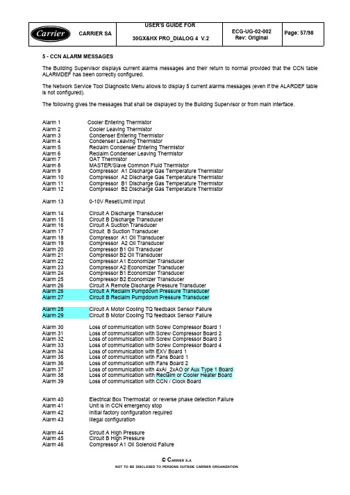
5 - CCN ALARM MESSAGESThe Building Supervisor displays current alarms messages and their return to normal provided that the CCN table ALARMDEF has been correctly configured.The Network Service Tool Diagnostic Menu allows to display 5 current alarms messages (even if the ALARDEF table is not configured).The following gives the messages that shall be displayed by the Building Supervisor or from main interface.Alarm 1Cooler Entering ThermistorAlarm 2Cooler Leaving ThermistorAlarm 3Condenser Entering ThermistorAlarm 4Condenser Leaving ThermistorAlarm 5Reclaim Condenser Entering ThermistorAlarm 6 Reclaim Condenser Leaving ThermistorAlarm 7OAT ThermistorAlarm 8 MASTER/Slave Common Fluid ThermistorAlarm 9Compressor A1 Discharge Gas Temperature ThermistorAlarm 10 Compressor A2 Discharge Gas Temperature ThermistorAlarm 11Compressor B1 Discharge Gas Temperature ThermistorAlarm 12Compressor B2 Discharge Gas Temperature ThermistorAlarm 13 0-10V Reset/Limit InputAlarm 14 Circuit A Discharge TransducerAlarm 15 Circuit B Discharge TransducerAlarm 16 Circuit A Suction TransducerAlarm 17 Circuit B Suction TransducerAlarm 18 Compressor A1 Oil TransducerAlarm 19Compressor A2 Oil TransducerAlarm 20Compressor B1 Oil TransducerAlarm 21 Compressor B2 Oil TransducerAlarm 22Compressor A1 Economizer TransducerAlarm 23 Compressor A2 Economizer TransducerAlarm 24Compressor B1 Economizer TransducerAlarm 25Compressor B2 Economizer TransducerAlarm 26Circuit A Remote Discharge Pressure TransducerAlarm 26Circuit A Reclaim Pumpdown Pressure TransducerAlarm 27Circuit B Reclaim Pumpdown Pressure TransducerAlarm 28 Circuit A Motor Cooling TQ feedback Sensor FailureAlarm 29 Circuit B Motor Cooling TQ feedback Sensor FailureAlarm 30 Loss of communication with Screw Compressor Board 1Alarm 31Loss of communication with Screw Compressor Board 2Alarm 32Loss of communication with Screw Compressor Board 3Alarm 33Loss of communication with Screw Compressor Board 4Alarm 34Loss of communication with EXV Board 1Alarm 35Loss of communication with Fans Board 1Alarm 36Loss of communication with Fans Board 2Alarm 37Loss of communication with 4xAI_2xAO or Aux Type 1 BoardAlarm 38Loss of communication with Reclaim or Cooler Heater BoardAlarm 39Loss of communication with CCN / Clock BoardAlarm 40Electrical Box Thermostat or reverse phase detection FailureAlarm 41Unit is in CCN emergency stopAlarm 42Initial factory configuration requiredAlarm 43Illegal configurationAlarm 44Circuit A High PressureAlarm 45 Circuit B High PressureAlarm 46 Compressor A1 Oil Solenoid FailureAlarm 47 Compressor A2 Oil Solenoid FailureAlarm 48 Compressor B1 Oil Solenoid FailureAlarm 49 Compressor B2 Oil Solenoid FailureAlarm 50 Compressor A1 Prestart Low Oil PressureAlarm 51Compressor A2 Prestart Low Oil PressureAlarm 52Compressor B1 Prestart Low Oil PressureAlarm 53 Compressor B2 Prestart Low Oil PressureAlarm 54 Circuit A Low Oil LevelAlarm 55Circuit B Low Oil LevelAlarm 56 Circuit A Low Suction TemperatureAlarm 57Circuit B Low Suction TemperatureAlarm 58Circuit A High Suction TemperatureAlarm 59 Circuit B High Suction TemperatureAlarm 60Circuit A Low Discharge SuperheatAlarm 61Circuit B Low Discharge SuperheatAlarm 62Compressor A1 Maximum Delta Pressure Check Oil Line Alarm 63 Compressor A2 Maximum Delta Pressure Check Oil Line Alarm 64Compressor B1 Maximum Delta Pressure Check Oil Line Alarm 65 Compressor B2 Maximum Delta Pressure Check Oil Line Alarm 66Loss of communication with System ManagerAlarm 67Master/Slave communication FailureAlarm 68 Compressor A1 Low Oil PressureAlarm 69Compressor A2 Low Oil PressureAlarm 70Compressor B1 Low Oil PressureAlarm 71 Compressor B2 Low Oil PressureAlarm 72 Cooler Freeze ProtectionAlarm 73Circuit A Condenser FreezeAlarm 74 Circuit B Condenser FreezeAlarm 75 Cooler Interlock FailureAlarm 76Condenser Lock FailureAlarm 77Compressor A1 High CurrentAlarm 78Compressor A2 High CurrentAlarm 79Compressor B1 High CurrentAlarm 80Compressor B2 High CurrentAlarm 81Cooler Pump 1 DefaultAlarm 82Cooler Pump 2 DefaultAlarm 83Circuit A Reclaim Pumpdown FailureAlarm 84Circuit B Reclaim Pumpdown FailureAlarm 85Reclaim Operation Failed by Condenser Flow Switch Alarm 86Master chiller configuration errorAlarm 87Service maintenance alertAlarms compressorAlarm 101Compressor A1 Motor Temperature Too HighAlarm 102Compressor A1 Motor Temperaure Out of Range Alarm 103Compressor A1 High Pressure SwitchAlarm 104Compressor A1 Over CurrentAlarm 105Compressor A1 Lock RotorAlarm 106Compressor A1 Ground FaultAlarm 107Compressor A1 Phase Loss L1Alarm 108Compressor A1 Phase Loss L2Alarm 109Compressor A1 Phase Loss L3Alarm 110Compressor A1 Unbalance > 14 %Alarm 111Compressor A1 Unbalance > 18 %Alarm 112Compressor A1 No Motor CurrentAlarm 113Compressor A1 Star Delta Starter FailureAlarm 114Compressor A1 Contactor FailureAlarm 115Compressor A1 Unable To StopAlarm 116Compressor A1 Phase ReversalAlarm 117Compressor A1 MTA Configuration Header FaultAlarm 201Compressor A2 Motor Temperature Too High Alarm 202Compressor A2 Motor Temperature Out of Range Alarm 203Compressor A2 High Pressure SwitchAlarm 204Compressor A2 Over CurrentAlarm 205Compressor A2 Lock RotorAlarm 206Compressor A2 Ground FaultAlarm 207Compressor A2 Phase Loss L1Alarm 208Compressor A2 Phase Loss L2Alarm 209Compressor A2 Phase Loss L3Alarm 210Compressor A2 Unbalance > 14 %Alarm 211Compressor A2 Unbalance > 18 %Alarm 212Compressor A2 No Motor CurrentAlarm 213Compressor A2 Star Delta Starter FailureAlarm 214Compressor A2 Contactor FailureAlarm 215Compressor A2 Unable To StopAlarm 216Compressor A2 Phase ReversalAlarm 217Compressor A2 MTA Configuration Header Fault Alarm 301Compressor B1 Motor Temperature Too High Alarm 302Compressor B1 Motor Temperature Out of Range Alarm 303Compressor B1 High Pressure SwitchAlarm 304Compressor B1 Over CurrentAlarm 305Compressor B1 Lock RotorAlarm 306Compressor B1 Ground FaultAlarm 307Compressor B1 Phase Loss L1Alarm 308Compressor B1 Phase Loss L2Alarm 309Compressor B1 Phase Loss L3Alarm 310Compressor B1 Unbalance > 14 %Alarm 311Compressor B1 Unbalance > 18 %Alarm 312Compressor B1 No Motor CurrentAlarm 313Compressor B1 Star Delta Starter FailureAlarm 314Compressor B1 Contactor FailureAlarm 315Compressor B1 Unable To StopAlarm 316Compressor B1 Phase ReversalAlarm 317Compressor B1 MTA Configuration Header Fault Alarm 401Compressor B2 Motor Temperature Too High Alarm 402Compressor B2 Motor Temperature Out of Range Alarm 403Compressor B2 High Pressure SwitchAlarm 404Compressor B2 Over CurrentAlarm 405Compressor B2 Lock RotorAlarm 406Compressor B2 Ground FaultAlarm 407Compressor B2 Phase Loss L1Alarm 408Compressor B2 Phase Loss L2Alarm 409Compressor B2 Phase Loss L3Alarm 410Compressor B2 Unbalance > 14 %Alarm 411Compressor B2 Unbalance > 18 %Alarm 412Compressor B2 No Motor CurrentAlarm 413Compressor B2 Star Delta Starter FailureAlarm 414Compressor B2 Contactor FailureAlarm 415Compressor B2 Unable To StopAlarm 416Compressor B2 Phase ReversalAlarm 417Compressor B2 MTA Configuration Header Fault。
PLC资料软件
121. MODEC程序转换成FX-GP-WIN下的程序软件
122. Medoc2.3F系列三菱PLC编程软件DOS版
123. GX-Simulator6中文版
124. FX-PCS-WIN-2.3E三菱的编程软件
125. FC系列PLC上位机编程工具 fcp30v32.zip
28. FX系列PLC通信手册、中文
29. FX系列PLC专用协议通信指令格式详解
30. FX系列微型可编程控制器PLC样本
31. GPP-WIN LLT 使用手册MANUAL
32. GPPW操作手册
33. Gppw中文使用手册
34. MEDOC三菱PLC软件包使用(中文)
35. MELSEC_MEDOC_PLUS编程软件参考手册
77. 三菱通信线的图纸说明
78. 三菱小阿发Alpha编程手册
79. 三菱小阿发Alpha软件手册
80. 三菱小阿发Alpha系列AL-232CAB硬件手册
81. 三菱小阿发Alpha系列AL-ASI-BD硬件手册
82. 中央空调节能控制系统(中文)
三菱FX软件目录
83. 位置控制器软件SWOD5F-FXVPS-E
33#:三菱PLC中文版教学软件FX-TRN-BEG-C 1CD 100元/套
三菱电机最新推出的FX-TRN-BEG-C将虚拟舞台和专家操作指导合成一起,学习通用梯形图逻辑编程。无需其他培训工具,将软件装在个人电脑上即可开始!
36. MITSUBISHI FX系列PLC特殊功能模块
37. MITSUBISHI FX系列PLC应用指令
雷克萨斯2024款GX产品宣传手册说明书

EXCEED ALL EXPECTATIONS 8,000 /6,990 /6,780LB TOWING CAPACITY4(PREMIUM / LUXURY / LUXURY+)8,000LB TOWING CAPACITY4GX550 OVERTRAIL4WDFULL-TIME4WDFULL-TIME349HORSEPOWER13.4-LITER V6 TWIN-TURBO ENGINE349HORSEPOWER13.4-LITER V6 TWIN-TURBO ENGINE 479LB-FT TORQUE1479LB-FT TORQUE1GX550 PREMIUM /GX550 LUXURY26° / 23° / 23° (PREMIUM)26° / 23° / 21° (LUXURY)APPROACH / BREAKOVER / DEPARTUREANGLE26° / 24° / 22°APPROACH / BREAKOVER / DEPARTUREANGLE10-SPEEDDIRECT-SHIFTAUTOMATIC TRANSMISSION10-SPEEDDIRECT-SHIFTAUTOMATIC TRANSMISSIONDIMENSIONSOVERALL LENGTH 197.04 IN / WHEELBASE 112.2 IN / WIDTH 83.22 IN (+ MIRRORS) / HEIGHT 75.59 IN (PREMIUM), 75.39 IN (LUXURY), 76.18 IN (OVERTRAIL)This is luxury that refuses to quit. Introducing the all-new 2024 GX. A bold new take on the iconic SUV. Where capability and refinement intersect to take you beyond everything you once thought possible. Take control of every drive with a 349-horsepower1 engine and proven four-wheel drive system. Indulge in up to three rows of finely appointed seating and the advanced Lexus Interface2 system. And for those who find exhilaration in pushing every limit, the first-ever GX Overtrail is designed to take on any challenge. In addition to the optimized visibility provided by the GX’s enthusiast-inspired flat dash, the Overtrail features trail-ready exterior appointments, increased ground clearance, a robust suite of off-road3 technologies and 33-inch all-terrain tires—the largest standard tires ever fitted to a Lexus. It’s time to amplify every adventure. It’s time to experience the new GX.FEATURESINDIVIDUAL OPTIONS GX PREMIUMStandard features:Mechanical & Performance8,000-lb towing capacity 4349-horsepower 1 3.4L V6 twin-turbo engine10-speed automatic transmissionFull-time 4WDTorsen ®5limited-slip center differentialwith locking feature Exterior20-in alloy wheelsPremium T riple-Beam LED headlampsPower-folding outside mirrorsRunning boardsPower rear doorPower tilt-and-slide moonroof with roof railsTow hitch 4InteriorSeating for sevenNuLuxe ®-trimmed, 8-way power-adjustable,heated and ventilated front seats with adjustable headrestsLeather-trimmed steering wheelSix USB-C ports 6120V /400-watt AC power outlet 7 in cargo area12.3-in multi-information displayInterior ambient illumination10-speaker Lexus Premium Sound SystemSafety / A dvanced TechnologiesLexus Safety System+ 3.08Intuitive Parking Assist with Auto Braking 9Blind Spot Monitor 10 with Rear Cross-T raffic Alert 11Connected TechnologiesLexus Interface 2 with 14-in touchscreen displaySafety Connect 2 with up to 10-year trial*Service Connect 2 with up to 10-year trial*Remote Connect 2 3-year trial*Wi-Fi Connect 2(AT&T hotspot ) with up to30-day/3GB trial* Drive Connect 2with Cloud Navigation, IntelligentAssistant and Destination Assist 3-year trial* Wireless Apple CarPlay ®12 integrationWireless Android Auto™13 compatibilityOptionsCold Area Package: Heated leather-trimmedsteering wheel, windshield wiper de-icer, headlamp washer, fast-response interior heaterGX PREMIUM+Includes Premium features, and adds or replaces:Exterior Power Rear Door with Kick Sensor 14LED foglamps Interior Power tilt-and-telescoping steering wheel Heated leather-trimmed steering wheel Thematic Ambient Illumination Lexus Memory System for driver’s seat, outside mirrors and steering wheel Heated second-row outboard seats Wireless phone charger 15 Panoramic View Monitor 16Power-folding third-row seat Safety / A dvanced Technologies Intuitive Parking Assist with Auto Braking and Rear Pedestrian Detection 17 Options Digital Key 18 (requires Remote Connect 2 subscription, 3-year trial included )* Heated second-row captain’s chairs (seating for six )Cold Area Package: Windshield wiper de-icer, headlamp washer, fast-response interior heater GX LUXURY Includes Premium+ features, and adds or replaces:Mechanical & Performance 6,990-lb towing capacity 4Exterior 22-in alloy wheels Outside mirrors with puddle lamps Interior 10-way heated and ventilated power driver’s seat Front massaging seats Semi-aniline leather–trimmed interior 4-way adjustable front headrests Second-row manual sunshade Illuminated door sills Options Digital Key 18 (requires Remote Connect 2 subscription, 3-year trial included )* Heated second-row captain’s chairs (seating for six )Mark Levinson ®19 21-speaker, 1,800-watt Surround Sound Cold Area Package: Windshield wiper de-icer, headlamp washer, fast-response interior heater GX LUXURY+Includes Luxury features, and adds or replaces:Mechanical & Performance 6,780-lb towing capacity 4Adaptive Variable Suspension Exterior Automatic power-extending running boards Dynamic Sky panorama glass roof Interior Mark Levinson 21-speaker, 1,800-watt Surround Sound Digital Rearview Mirror Cool box Options Digital Key 18 (requires Remote Connect 2 subscription, 3-year trial included )* Heated second-row captain’s chairs (seating for six )Cold Area Package: Windshield wiper de-icer, headlamp washer, fast-response interior heater GX OVERTRAIL Includes Premium features, and adds or replaces:Mechanical & Performance Electronic Kinetic Dynamic Suspension System (E-KDSS ) Adaptive Variable Suspension Electronically controlled locking rear differential Crawl Control 20 with T urn Assist Downhill Assist Control 21 Multi-Terrain Select Exterior 18-in alloy wheels 33-in all-terrain tires Black utility roof rails Headlamp washers LED foglamps Windshield wiper de-icer Interior Seating for five Heated leather-trimmed steering wheel Four USB-C ports 6 Safety / A dvanced Technologies Panoramic View Monitor 16 with Multi-T errain Monitor Options Cool box GX OVERTRAIL+Includes Overtrail features, and adds or replaces:Exterior Power Rear Door with Kick Sensor 14Outside mirrors with puddle lamps Interior Power tilt-and-telescoping steering wheel Thematic Ambient Illumination Lexus Memory System for driver’s seat, outside mirrors and steering wheel Heated second-row outboard seats Wireless phone charger 1510-way heated and ventilated power driver’s seat Front massaging seats 4-way adjustable front headrests Second-row manual sunshade Illuminated door sills Safety / A dvanced Technologies Intuitive Parking Assist with Auto Braking and Rear Pedestrian Detection 17 Options Digital Key 18 (requires Remote Connect 2 subscription, 3-year trial included)*Cool box Mark Levinson 21-speaker, 1,800-watt Surround Sound Available on all models:T raffic Jam Assist 22 (requires Drive Connect 2 subscription, 3-year trial included )*Head-Up Display Tonneau cover*4G network dependentEXTERIOR COLORSINTERIOR COLORS INTERIOR TRIMS *Additional chargeEMINENT WHITE PEARL*Eminent White Pearl *Nebula Gray Pearl Caviar Nightfall Mica Atomic Silver Incognito Nori Green Pearl Earth *Dapple Gray Dapple Gray Black Black Saddle Tan Saddle Tan GX OVERTRAIL / GX OVERTRAIL+Material NuLuxe NuLuxe / Ultrasuede Semi-aniline leather INTERIOR COLOR GX LUXURY / GX LUXURY+GX PREMIUM / GX PREMIUM+Color INTERIOR TRIM Black Grained T rim / Brown Grained Trim Black Grained Trim / Brown Grained Trim Black Grained Trim Black/Olive Chateau/Olive EXTERIOR COLOR • • • • • • • • • • • • • • • • • • • • • •• • • • • • • • • • • • • • • • • • • • • • • • • • • • • •WITH BLACK ONYX ROOF WITH BLACK ONYX ROOF OPTIONAL BLACK ONYX ROOF*OPTIONAL BLACK ONYX ROOF*OPTIONAL BLACK ONYX ROOF*OPTIONAL BLACK ONYX ROOF*OPTIONAL BLACK ONYX ROOF*OPTIONAL BLACK ONYX ROOF* • •GX Overtrail+ prototype shown.1. Ratings achieved using required premium unleaded gasoline w/ an octane rating of 91 or higher. If premium fuel is not used, performance will decrease.2. Lexus Interface services depend on factors outside of Lexus’ control in order to operate, including 4G network availability, a cellular connection and GPS signal. Without any one or more of these things, operability may be limited or precluded, including access to response center and emergency support. Services vary by vehicle and are subject to change at any time without notice. Requires app download/registration and subscription after trial (if applicable). Terms of Use apply. Data charges may apply. See Owner’s Manual and https:///lexusdrivers/technology/interface for additional limitations and details. To learn about Lexus’ Interface data collection, use, sharing and retention practices, please visit https:///privacy. All trials begin on original purchase or lease date of new vehicle, with the exception of Wi-Fi for which trial begins at time of activation. Paid subscription required after trial (if applicable). For Safety Connect, stolen vehicle police report required to use Stolen Vehicle Locator. Automatic Collision Notification activates only in limited circumstances. For Remote Connect, use only if aware of circumstances surrounding vehicle and it is legal and safe to do so (e.g., do not remotely start a gas engine vehicle in an enclosed space or if vehicle is occupied by a child). Drive Connect service not available in every city or roadway. For Service Connect, information provided is based on the last time data was collected from vehicle and is not real-time data. Wi-Fi Connect service not available everywhere or in every vehicle. Valid in contiguous U.S. and Alaska. Up to 5 devices supported. Integrated Streaming requires subscription for third-party provider services. Wi-Fi Connect trial (if applicable) begins at time of enrollment and expires the earlier of: 3GB of data is used or 30 days after enrollment.3. The Lexus GX is designed to meet most off-road driving requirements, but off-roading is inherently dangerous and may result in personal injury or vehicle damage. Lexus encourages responsible operation to help protect you, your vehicle and the environment.4. Never tow beyond a vehicle’s published towing capacities.5. Torsen® is a registered trademark of JTEKT Torsen, Inc.6. Charging may not be compatible with all mobile phones, smart devices, tablets, e-readers, MP3/WMA players and like models.7. Rated for 400 watts for a single two-prong outlet. See Owner’s Manual for additional limitations and details.8. Lexus Safety System+ effectiveness depends on many factors including road, weather and vehicle conditions. Drivers responsible for paying attention to their surroundings and driving safely. See Owner’s Manual for limitations. 9. Intuitive Parking Assist (IPA) may warn drivers of front and rear collisions with certain objects when traveling at low speeds. Drivers should visually confirm clearance during use. See Owner’s Manual for limitations. 10. Do not rely exclusively on Blind Spot Monitor. Look over shoulder and use turn signal. See Owner’s Manual for limitations. 11. Do not rely exclusively on the Rear Cross-T raffic Alert. Visually confirm clearance during use. See Owner’s Manual for limitations. 12. Requires compatible smartphone. Operability depends on network availability, a cellular connection and GPS signal. Services subject to change at any time without notice. Data charges may apply. To learn more, go to https:///lexus/home. To learn more about Lexus’ connected services data collection, use, sharing and retention practices, please visit https:///privacy. Apple CarPlay and iPhone are registered trademarks of Apple Inc. 13. To wirelessly use Android Auto on your car display, you need a compatible Android smartphone with an active data plan. Y ou can check which smartphones are compatible at g.co/androidauto/requirements. Operability depends on network availability, a cellular connection and GPS signal. Services subject to change at any time without notice. Data charges may apply. To learn more, go to https:///lexus/home. To learn more about Lexus’ connected services data collection, use, sharing and retention practices, please visit https:///privacy. Android and Android Auto are trademarks of Google LLC. 14. Installation of a tow hitch receiver or other accessories located near the rear bumper may require disabling or removing the kick sensor, and the sensor operation setting in your vehicle should be turned off. See Owner’s Manual for limitations. 15. Wireless charging may not be compatible with all mobile phones, smart devices, tablets, e-readers, MP3/WMA players and like products. 16. The Panoramic View Monitor does not provide a comprehensive view of the area surrounding your vehicle. Look around to confirm clearance. See Owner’s Manual for limitations. 17. Intuitive Parking Assist may warn drivers of, and potentially brake for, rear collisions with certain objects when traveling at low speeds. Drivers should visually confirm clearance during use. See Owner’s Manual for limitations. 18. Digital Key requires active Remote Connect trial or subscription. Use only if aware of circumstances surrounding vehicle and it is legal and safe to do so (e.g., do not remotely start a gas-engine vehicle in an enclosed space or if vehicle is occupied by a child). Remote Connect depends on certain factors outside of Lexus’ control in order to operate, including 4G network availability, a cellular connection and GPS signal. Without any one or more of these things, operability may be limited or precluded. Services subject to change at any time without notice. Digital Key also requires Bluetooth connectivity. Remote Connect is included with select paid Connected Services packages. See your Lexus dealer for details. Terms of Use apply. Data charges may apply. See Owner’s Manual and https:///lexusdrivers/technology/interface for additional details. To learn about Lexus Interface’s connected services data collection, use, sharing and retention practices, please visit https:///privacy. Trial period begins on original purchase or lease date of new vehicle. Paid subscription required after trial (if applicable). Terms of Use apply. 19. Mark Levinson is a registered trademark of Harman International Industries, Inc. 20. Crawl Control is designed for driving on difficult terrain at low speeds and assists the driver by controlling acceleration and braking, allowing the driver to focus on steering. See Owner’s Manual for additional limitations. 21. Downhill Assist Control is designed to help the driver maintain vehicle control and speed on steep downhill descents, and is not a substitute for safe driving judgment and practices. Factors including speed, grade, surface conditions and driver input can all affect the ability of DAC to prevent a loss of control. See Owner’s Manual for additional limitations. 22. T raffic Jam Assist requires an active trial or subscription to Drive Connect. Traffic Jam Assist is not an automated driving system, requires driver supervision at all times, and is designed to function on controlled access freeways at speeds of 25 mph or less. Use this system in accordance with applicable laws. Before operating, refer to Owner’s Manual for additional instructions and limitations. 23. Ultrasuede is a registered trademark of Toray Industries, Inc.Lexus strives to build vehicles to match customer interest, and thus they typically are built with popular options and option packages. Not all options/packages are available separately, and some may not be available in all regions of the country. Lexus Interface display shown may not reflect most recent over-the-air enhancements. See for information about options/packages commonly available in your area. If you would prefer a vehicle without any or with different options, contact your dealer to check for current availability or the possibility of placing a special order. Specifications, features, equipment, technical data, performance figures, options, and color and trim are based upon information available at time of publishing, are subject to change without notice, and are for mainland U.S.A. vehicles only. Vehicles shown may be prototypes, shown using visual effects and/or shown with options. Actual models may vary. Colors depicted may vary based on multiple factors, including ambient lighting and the format in which they are being viewed (e.g., computer, mobile device, or print). See your Lexus dealer for details. Lexus reminds you to wear seatbelts, secure children in rear seat, obey all traffic laws and drive responsibly. For more information, call 800-USA-LEXUS (872-5398) or visit . To learn more about your financing options, contact your Lexus dealer or call Lexus Financial Services at 800-874-7050. ©2023 Lexus, a Division of Toyota Motor Sales, U.S.A., Inc.P4-7665 (06/23)。
三菱PLC软件GX与MX系列软件介绍
10
GX Simulator
提供了PLC 的仿真调试环境
11
GX Simulator
PLC 仿真和调试实际效果图
12
GX Explorer Ver.2
13
GX Explorer Ver.2
GX Explorer Ver.2 提供了PLC维护必要的功能 提供了PLC维护必要的功能 PLC
14
GX Explorer Ver.2
MELSEC可编程控制器的设定监控工具 MELSEC可编程控制器的设定监控工具
■ ■
MELSEC智能模块的初始设定! 通过简单操作,完成设定,监控,设计及启动,减少大量的编程工作
25
GX Configurator-CC
用于A 系列CC-Link主站模块的CC-Link网络参数设定,无需再编制顺控程序来 设定参数 在软件图形输入屏幕中简单设定
Web功能 将PLC的状态发EMAIL给手机或计算机 手机,计算机上,可以通过浏览器对软元件进行监控/测试 MELSOFT连接功能 在客户机上,可使用GXExplorer GXExplorer 丰富的运行环境 Windows计算机 PC CPU模块 Web模块 多种用途 通用电话,LAN,局域网 模拟ADSL,光纤,手机
预设值 重合输出点设置 功能选择设置 采样/定时设置 环形计数器上限值 环形计数器下限值
监视/测试屏幕
监视 测试
自动刷新设置屏幕
不需要知道地址
高速计数模块 缓存中数据:
1 当前值 2 锁存计数值 3 采样计数值 4 溢出检测 5 其它 30
自动刷新 设定对应的CPU软元件 软元件 设定对应的 CPU软元件
自动刷新设置屏幕 串行通信模块 缓存中数据:
各种汽车型号

美国车
通用:
柯西佳2.2、雪弗兰子弹头3.1、3.8、凯迪拉克5.7、庞帝克、C20农夫车
别克(林荫大道、世纪)、开拓者SUV、S10、GMC,绅宝
上海别克GLX、GL、GS、GL8商务车、君威、凯越2.0、赛欧1.6
福特:
林肯城市、大陆CONTINENTAL、领航员、马克、天霸2.3TEMPO、维多利亚、风之星宇宙星、俱乐部、探险者EXPLORER、金牛3.0TAURUS堂皇、护卫者、翼虎水星村民3.0(云豹6480)VILLAGER、大侯爵、黑貂SABLE、环宇
MR2:AW1# SW20 ZZW30 AW11 SW21 AW11
戴那DYNA:YH8# LH80 YH81 LH80 LY100 YY100 YY5# YY6# LY60 LY21# YY211 KDY22# KDY23# KDY25# BU6# BU7# BU8#
YU210 RZU100 XZU30# XZU320 XZU330 JU20 RU30 HU30 HU40 HU50 WU40 RU75 RU85 XZU402 XZU430
三菱车系配件车型:
吉普: L047 4G54、V31 4G64、V32 4G54、V33 6G72、V43 6G72、V45 6G74、V73 6G72. V754 G63
猎豹吉普:CJY6421D、CJY6470E
太空车: N31 4G93、N34 4G64、N44、N84 4G64 、6G72、N11W
ACV30 VZV20 CV20 CV30 MCV2# AHV40 GSV40 ACV40 SV25 SV35
吉仙达CRESSIDA/CRESTA:
RX7# MX7# GX7# GX8# RX8# MX8# GX91 JZS91 JZS93 GX100 GX10# JZX10# TX62 RX6# LX60 YX70 GX71 LX7# GX81
- 1、下载文档前请自行甄别文档内容的完整性,平台不提供额外的编辑、内容补充、找答案等附加服务。
- 2、"仅部分预览"的文档,不可在线预览部分如存在完整性等问题,可反馈申请退款(可完整预览的文档不适用该条件!)。
- 3、如文档侵犯您的权益,请联系客服反馈,我们会尽快为您处理(人工客服工作时间:9:00-18:30)。
Carrier 电路板诊断
电路板名称:SCPM
电路板号码:CE号码用户号码
CEPL 130416-03 32GB500 402EE
CEPL 130416-02 32GB500 232EE
CEPL 130416-01 32GB500 232EE
1. 测试步骤
首先,重要的是记住,SCPM的作用是保护压缩机。
SCPM用于监测冷却系统,发送报警去指示不正常情况,在必要时关闭系统保护压缩机免于损坏。
为评估一个已被怀疑的故障需要做如下测试:
1.1 系统与报警
当一个客户因为压缩机已关闭而打来电话时,为决定关闭的原因首先需要去评估系统和报警部分,而不是假设正在保护压缩机运行中SCPM已经发生故障。
1.2 外部损坏
检察电路板是否有明显的外部损坏,例如元件的破损或脱落。
当电路板掉落在地上,受到工具或其他物体的碰撞,以及在其他过程中不适当的处理都可能导致这种外部损坏。
1.3 布线检查
1.确保所有接口插头联接紧密。
2.确保连线没有松动与脱落。
1.4 传感器检查
确保与SCPM联接的传感器没有损坏。
1.5 开关设置
确认设置开关“ADDR”, “MTA”和“FNFY”设置正确。
如果“ADDR”设置不正确,电路板将不能通信。
如果“MTA”设置不正确,将产生报警。
如果“RNFY”设置不正确,可能导致起动错误的起始程序或导致正在使用的传感器可能给出错误数据。
1.6 二极管D1
用电表检查二极管D1(位置在大电容C2和MOV1之间)证明D1没有短路。
在SCPM1和 SCPM2 上,当电源发生故障时,不正常的电源会导致D1短路。
1.7工作状态LED (红LED)
电路接通电源时,红LED给出电路板工作状态。
1.红LED以800毫秒开,200毫秒关闪烁表示启动程序运行和电路板
没有下载软件。
2.红LED以1秒开,1秒关闪烁表示应用程序运行正常。
3.红LED亮而不闪烁表示电源接通,而微处理器工作不正常。
4.红LED闪烁,但并非像1和2所描述,表示微处理器电路出现问
题。
5.红LED灭,表示电源或微处理器发生故障。
1.8 通信
系统控制器经常出现“NO COMMUNICATION”错误。
任何SCPM 的故障都可能导致这个错误发生。
例如电源故障将会导致无通信错误。
在确保按前面所述步骤检查后,执行下面步骤:
1.确保通信联接正确。
2.开启系统电源,确认主控制电路板绿灯闪烁。
如果绿灯不闪烁,则
主控制电路板有问题。
3.检查绿灯,至少每秒闪烁一次。
否则存在通信故障。
1.9 软件
1.9.1 确保使用正确版本软件。
在PC机上可用COMTEST程序,按下列
步骤可以检查软件版本。
1.关闭电路板电源,连接通信口,选择 DOWNLOADER, RESTART,
CONTINOUS WARM STARTS。
2.接通电路板电源,应该出现SUCCESS 窗口,点击 OK。
3.选择 TOOLS, MEMORY EDITOR。
4.对电路板版本1和版本2,输入16位数‘10402A”在”Block Address”
格中,点击 Read。
5.对SCPM3输入16位数‘1045A0”在”Block Address”格中,点击
Read。
6.版本号出现在ASCII 框中。
7.如果版本号是128.13, 表示用于工厂检验,在现场情况下不得使用。
8.由软件号码确认是否使用最新软件。
9.为恢复电路板到正常运行,选择 DOWNLOADER, EXCUTE, 应出现
“SUCCESS”窗口,点击 OK。
2.0 没有问题
如果按上述步骤检查没有发现任何问题,可再次在系统中使用这块电路板。
如果在系统中电路板再次发生故障,请将电路板返回工厂。