SD_SSP_015 可用性检查业务_V2.0
数据中心网络安全检查清单的必备品

数据中心网络安全检查清单的必备品随着互联网的普及和信息化进程的加速,数据中心的重要性日益突显。
作为企业数据存储和处理的重要场所,数据中心的安全性备受关注。
网络安全作为数据中心安全的重要组成部分,一直是企业重点关注和加强的问题。
为了保障数据中心网络安全,我们需要制定一份数据中心网络安全检查清单的必备品,以确保数据中心网络安全得到充分保障。
1. 网络设备的安全配置数据中心中的网络设备是数据传输和通信的关键组成部分,安全配置是确保网络设备正常运行和数据安全的关键。
必备品包括:- 防火墙:确保数据中心网络设备都连接有防火墙,能够对进出数据进行有效的过滤和检查,防止来自外部的攻击和恶意程序的侵入。
- 交换机和路由器:对交换机和路由器进行安全配置,包括对访问控制列表(ACL)的配置、端口安全、MAC地址绑定等,确保只有授权的设备和用户可以接入数据中心网络,防止未授权的访问和攻击。
- 网络隔离:在数据中心网络中设置不同的虚拟局域网(VLAN),实现数据的隔离和安全传输,防止数据泄露和传播。
为了进一步加强数据中心的网络安全,必备品还包括一些专门的网络安全设备的部署,例如:- 入侵检测系统(IDS)和入侵防御系统(IPS):通过对流量进行深度检测和分析,及时发现和阻止网络中的异常活动和攻击,保障数据中心网络的安全。
- 安全信息和事件管理系统(SIEM):对数据中心的安全事件和日志进行集中管理和分析,及时发现异常行为和安全漏洞,帮助企业及时做出反应和处理。
- 防病毒和恶意软件检测系统:在数据中心网络中设置专门的防病毒和恶意软件检测系统,确保数据中心不受病毒和恶意软件的感染,并在第一时间发现和隔离风险。
3. 网络访问控制和用户权限管理对数据中心网络的访问控制和用户权限管理也是确保网络安全的必备品。
包括:- 用户身份认证和授权:对数据中心网络的用户进行严格的身份认证和授权管理,确保只有合法的用户可以访问数据中心网络,并且只能访问到其被授权的资源。
德讯科技运维操作审计(堡垒主机)解决方案在金融行业的应用

德讯科技运维操作审计(堡垒主机)解决方案在金融行业的应用随着网络化的普及和发展,金融行业电子网络信息化建设也在不断深入,服务手段日益多样化,很多以计算机为依托的相关新业务不断出现,并逐步形成了一整套现代化的崭新模式。
近年来,从“数据大集中”到“多业务整合”的发展趋势已获得了我国金融业从业者广泛的认同,各级数据中心建设纷纷围绕业务发展的需要深入展开。
面对规模化的IT基础设施、日益复杂的应用系统和不断更新及交换的海量数据,数据中心安全性、稳定性在行业竞争舞台上扮演越来越重要的角色,成为当今时代金融行业迫切需要解决的问题。
【金融行业IDC业务现状及需求分析】下级机构运维过程中,缺少有效的技术监管手段金融行业的特点是组织机构庞大;地域空间分布分散;省级总行与其下属地市级支行之间的业务互联与数据信息交换基于复杂的广域网技术体系。
然而,在各地市级支行数据中心运维安全、内控风险的管理方面,省行只能用制度规范予以约束,并用人工方式进行监督,管理效果欠佳,效率低下,缺乏行之有效的技术辅助手段。
运维入口过多、运维通道不集中、运维工具分散金融业IDC常规的运维模式,是由省市各层各级运维人员基于本地客户端启用RDP/VNC/TELENT等远程协议工具直接访问目标设备,展开会话操作。
此模式导致运维入口过多(一台客户端提供一个运维入口)、运维通道相互独立(不同协议工具需要建立不同运维通道)、运维工具部署分散(协议工具分别安装于各运维客户端),造成了网内运维环境安全难以管理的局面。
需要应对行业新标准所提出的多人核实管理机制根据金融行业安全等级保护基本要求规定,对于核心设备及关键业务系统等高风险运维操作,需采用多人核实机制(即:同时获得两人以上授权情况下,才能发起相应的会话),以提升运维操作行为合规性控制的细粒度。
审计手段缺乏全面性,审计信息不够直观目前,金融业IDC现有的审计手段是基于操作系统日志的审计,只能定位到访问设备的IP地址、用户、时间等基本信息,无法准确、直观地追溯运维人员在目标设备上的会话过程,无法客观还原事故原因。
二层端口线路检查协议
二层端口线路检查协议
1. CDP(Cisco Discovery Protocol),由思科开发的一种用
于发现和查看连接到思科设备上的邻居设备信息的协议。
通过CDP,管理员可以查看连接到思科设备上的邻居设备的信息,包括设备类型、IP地址、设备型号等。
2. LLDP(Link Layer Discovery Protocol),一种开放标准
的二层协议,类似于CDP,用于发现和查看连接到网络设备上的邻
居设备信息。
与CDP不同的是,LLDP是一种开放标准协议,可以在
多种厂商的设备上使用。
3. UDLD(Unidirectional Link Detection),用于检测交换
机之间的单向链路的协议。
当交换机之间的链路出现单向通信时,UDLD可以检测到这种问题并发出警告,防止因单向链路导致的通信
故障。
4. STP(Spanning Tree Protocol),虽然STP不是专门用于
端口线路检查的协议,但它可以帮助检测和纠正网络中的环路,从
而保证网络的正常运行。
5. Ethernet OAM(Operations, Administration, and Maintenance),以太网运营、管理和维护协议,提供了一系列的OAM功能,包括链路状态检测、故障定位等,用于监控以太网链路
的状态和性能。
以上这些协议都可以用于进行二层端口线路的检查和监控,管
理员可以根据实际情况选择合适的协议来确保网络设备的正常运行。
同时,也可以结合使用多种协议来实现更全面的网络监控和故障排除。
SAP专业培训教材SD_SSP_005_代加工业务_V2.0

x’x’x’x信息---SAP SD标准业务蓝图流程●流程名称:代加工业务●流程编号:SD_SSP_005●发布日期:2009-3-04●版本: V2.0修改历史目录1.1 业务场景 (4)1.2 目标/宗旨 (4)1.3 流程概述 (4)1.4 SAP 流程图 (4)1.5 流程描述 (5)1.6 系统单据/配套报表 (6)1.7 特殊情况说明 (6)1.8 配置测试要点 (7)1.9 系统增强(USER EXIT) (8)1.1 业务场景我方与客户签订代加工服务协议,客户把原材料运到我方,我方生产部门对该原材料进行加工,加工成成品后再发给客户,此过程我方向客户收取代加工服务费用。
1.2 目标/宗旨代加工业务实际上是为客户提供原材料加工服务,而不是销售成品,此过程中的原料和成品货权都非我方,本流程通过在代加工订单上的服务物料确认代加工费用,而实际物料只作为库存移动的物料,在我方并不产生存货价值,这一流程更切合实际地反映代加工业务的本质。
1.3 流程概述1)先做代加工订单。
订单中有两类物料,一类是服务物料,确定代加工费和应收,另一类是用于物流移动的物料(成品物料),只有库存移动(服务物料与定价、开票相关,与货物移动无关;物流物料与定价、开票无关,体现货物移动并扣减库存)。
结算量根据合同(系统中以中转订单形式存在,物料描述来源和使用方法均同普通订单)以商检数量或地磅量为准。
在订单文本中输入入库原料信息(自物料主数据带入字段名,具体字段信息手工添加,即入库单的物料描述为手工输入文本),用于打印原料入库单。
2)501E将原料直接收入订单的特殊库存,此时不会产生财务凭证,因为E类的特殊库存不产生存货价值。
MMBE(库存总揽报表)中不会加入到总的非限制使用库存中,而是以订单的特殊库存体现在报表上3)生产直接用E库存(原料)生产,直接产出E的成品库存。
4)原销售订单开提单,601E发产成品,不产生财务凭证。
柔性检查作用域套件-USB 产品说明书
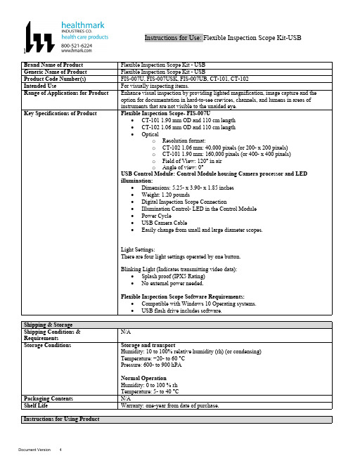
lInstructions for Use: Flexible Inspection Scope Kit-USB Brand Name of ProductFlexible Inspection Scope Kit - USB Generic Name of ProductFlexible Inspection Scope Kit - USB Product Code Number(s)FIS-007U, FIS-007USK, FIS-007UB, CT-101, CT-102Intended UseFor visually inspecting items.Range of Applications for ProductEnhance visual inspection by providing lighted magnification, image capture and the option for documentation in hard-to-see crevices, channels, and lumens in areas of instruments that are not visible to the unaided eye.Key Specifications of Product Flexible Inspection Scope- FIS-007U∙CT-101 1.90 mm OD and 110 cm length∙CT-102 1.06 mm OD and 110 cm length∙Opticalo Resolution format:o CT-102 1.06 mm: 40,000 pixels (or 200- x 200 pixels)o CT-101 1.90 mm: 160,000 pixels (or 400- x 400 pixels)o Field of View: 120° in airo Angle of view: 0°USB Control Module: Control Module housing Camera processor and LEDillumination:∙Dimensions: 5.25- x 3.90- x 1.85 inches∙Weight: 1.20 pounds ∙Digital Inspection Scope Connection∙Illumination Control- LED in the Control Module∙Power Cycle∙USB Camera Cable∙Easily change from small and large diameter scopes.Light Settings:There are four light settings operated by one button.Blinking Light (Indicates transmitting video data):∙Splash proof (IPX5 Rating)∙No external power needed.Flexible Inspection Scope Software Requirements:∙Compatible with Windows 10 Operating systems.∙USB flash drive includes software.Unpacking Flexible Inspection Scope:Carefully inspect for shipping damage. If there is any damage contact the shipping carrier and Heatlhmarkcustomer service 800-521-6224 immediately.USB Control Module: (Fig. 1).1.Digital Inspection Scope Connection 2.Illumination Control 3.Power Cycle B (Type C) on the right side of the boxFigure 1Flexible Inspection Scope™: (Fig. 2).∙CT-101 1.90 mm O.D. and 110 cm length ∙CT-102 1.06 mm O.D. and 110 cm lengthLarge1.90 mmSmall 1.06 mmFigure 2Flexible Inspection Scope™ Features3214Light/Illumination Settings: (Fig. 3).∙Five (5) light settingso Light on control indicats setting levelo Fifth setting is OFF∙Press light button to advance to next setting.∙Fifth setting turns the light OFF.Figure 3Power Cycle ButtonPress button to RESET camera (Fig. 4).Figure 41.Flexible Inspection Scope™ Plug (Fig. 5).Contains camera video connection as well as LED Light for illumination.1Figure 52.Flexible Working Length (Fig. 6).The portion of the Flexible Inspection Scope™ that is inserted into an item during visual inspection.The measuring scale markings on the Flexible Working Length are in centimeters (accuracy = ± 0.5 cm)2Figure 63.Distal Camera (Fig. 7).Distal portion of Flexible Inspection Scope™ that contains the camera lens3Figure 7SOFTWARE INSTALLATION:Note: This section is done only once when connecting the scope to the computer for the first time.∙System Requirements: MS Windows 10∙Install the Flexible Inspection Scope™ Software from the USB flash drive on a computer.Note: If you have any IT policies that may block this installation, please contact your IT team to give access to Healthmark scope viewer to install.1. Insert the USB Flash drive into your computer, and double click on the Healthmark Scope Viewer installer package to begin installation.2. The “Welcome to the Healthmark Scope Viewer Setup Wizard” screen pops up. Click on Next.3. Select the first tab Typical or setup type of your choice, click Next.4. Click Install and wait for installation to complete.5. Click Finish.STARTING SOFTWARE & CONNECTING SCOPE TO PC:(Fig 8).1.Open the Windows PC viewer software.2.Connect the Control Module to PC using USB Cable.3.Plug the Flexible Inspection Scope into the Control Module.4.In the viewer software, click Settings and Select USB Video Device, click on the desiredresolution, select the preferred Video Output Format, and then Click OK.5.Press the Power Cycle Button.Figure 86.Now you can start using the scope.Verifing OperationFollowing the steps listed below will ensure the proper use and performance of the Flexible Inspection Scope™. The Flexile Inspection Scope™ can be checked for normal operation by connecting it as described in the Startup section of this IFU.Normal operation includes:∙An image appearing on your computer monitor or HDMI Monitor.∙ A blinking light on Control Module near the Power Cycle button that indicates the image feed is transmitting.∙White light emitting from the distal end of the Digital Inspection Scope.∙An LED light on the control module top panel that indicates the light intensity of the device. Using SoftwareHealthmark Scope Viewer Software (Fig. 9).1.Capture button: Captures a Reference Image and saves it to the Reference Image folder.2.Main Image Window: Displays the image from the camera.3.Reference Image Window: Displays a reference image.4.Clear Button: Removes the image from the Reference image window.5.Open Reference Image button: Allows selection of a reference image from the Reference Imagefolder.6.Settings Button: Click to select the video camera and resolution settings.7.File Location Button: Click to change location where captured images are being saved.8.File Location Window: Shows the file path where captured images are being saved currently.9.Capture Image Button: Captures images and adds them to the File Location selected by the user(as shown in the File Location Window).10.Capture Video button: Click to record video. Click again to stop recording video.11.File Prefix: Type in text that you would like included in the file name of Captured Images.Figure 9Selecting Video Device or CameraFollow the directions below to select the video device or camera used to capture images using the Flexible Inspection Scope™ Viewer Software. (Fig. 10).1.Click Settings button in the lower left of the Scope Viewer software to display a list of videodevices or cameras being detected by your computer2.Select a device for capturing images using the Scope Viewera.The example below shows a webcam and USB Video Device in the Settings box. Select theUSB Video Device for the Flexible Inspection Scope™.b.You can also select your preferred Video Output Format from the dropdown box3.Click OK to view the selected Video Device.231Figure 10Capturing Still PicturesFollow the instructions for capturing still pictures from the Main Image Window.Select the Capture Image button. (Fig. 11).Figure 11Note: When an image is captured, “Image Captured” in red text will flash on the lower portion of the screen and a new file will appear in the Files Location.Capturing Video ImagesFollow the instructions below for capturing video from the Main Image Window.1.Select the Capture Video Button (Fig. 12).Figure 122.When the video is recording “Recording…” in red text will appear toward the bottom of thesoftware window.3.To stop recording, click Stop Capture. (Fig. 13).Figure 13Setting File PrefixFollowing the steps below allows you to create a file prefix that will appear after the underscore of image file names save to the File Location specified by the user.1.Click in the field next to File Prefix.2.Enter the characters that you would like to be included in the file name. (Fig 14).Figure 14Setting Location for Saved FilesFollowing the steps below allows you to set the file location of saved images using the Scope Viewer software.1.Click the File Location button.2.Select the file location you want to save captured images. (Fig 15).Figure 15Displaying Reference ImageThere are two ways to display a still image in the Reference Image Window on the Scope Viewer software.1.To display an image currently being displayed in the Main Image Window, click the Capture button. Note: The images will be saved in a file folder titled Reference Images in the designated File Location that the user specified in the File Location field. (Fig. 16).Figure 162.To display a saved image in the Reference Image Window from your File Location:a.Click the Open Reference Image button (Fig. 16 above).b.Select the file you want to display (Fig. 17 below).c.Click the OK Button, to display the image in the Reference Image Window. (Fig. 17).Figure 17Switching to a Different Flexible Inspection Scope™ on the Control Module:1.Press the Power button on the Control Module once.2.Disconnect the current Flexible Inspection Scope from the Control Module.3.Repeat the steps in the “STARTING SOFTWARE & CONNECTING SCOPE TO PC” procedure.Inserting Scope in ItemFigure 1Rotating Device to Avoid ObstacleFigure 2 Performing InspectionWipe down the Flexible Inspection Scope™ with a compatible wipe. Follow the manufacturer’s (Mfr.’s)Instructions for Use (IFU) for appropriate wipe usage. Click here to see the Chemical Compatibility Chart(PDF) for approved cleaning.The Flexible Inspection Scope™ is made of the same material as other common endoscopes. Any wipe,solution, or low temperature (≤ 60 °C [140 °F]) method intended for the reprocessing of endoscopes is likelycompatible with the Generation II Flexible Inspection Scope™ Catheters if used according to the productlabeling.Solutions Containing (Flexible Inspection Scope Only)Alcohol Ethoxylates Neutral or Near-Neutral pH DetergentsEnzymatic Cleaning Solutions Enzymatic DetergentsSodium Borated, Decahydrate Tetrapotassium PyrophosphateFlexible Inspection Scope™ has a fluid ingress protection rating of IPX7 (Waterproof) and can withstandimmersion in fluid up to one (1)-meter in depth for up to 30 minutes.Control Module USB has a fluid ingress protection rating of IPX5 (Water resistant) and can withstand asustained, low pressure water jet spray for up to three minutes.For Thorough Cleaning: CablesFollow the cleaning agent Mfr.’s IFU.1.Unplug and disconnect all components from the Control box prior to cleaning.2.Do not submerge or soak the cable for disinfection (cable is not waterproof).3.Wipe thoroughly with non-linting wipe moistened with facility approved neutral detergent. Use theappropriate brushes with detergent solution to remove any residues from areas that cannot bereached with the wipes.For Thorough Cleaning: Control Module1.Unplug and disconnect all components from the Control box prior to cleaning.2.Do not submerge or soak the cable for disinfection (Control Box is not waterproof).3.Wipe thoroughly with non-linting wipe moistened with facility approved neutral detergent. Use theappropriate brushes with detergent solution to remove any residues from areas that cannot bereached with the wipes.Note: Do NOT soak. Control Module and cables are not waterproof and should not be immersed.N/ACleaning –AutomatedDisinfection Control Module and CablesThese may be cleaned with alcohol based disinfectant wipes.Compatible agents (wipes and solutions) for disinfecting Flexible Inspection Scope™ and ControlModule:∙Hydrogen peroxide∙Isopropyl alcohol (IPA)∙Sodium hypochlorite (Bleach)∙Ortho-phenylphenol∙Quaternary ammonium.High-Level Disinfection (Flexible Inspection Scope™ Only)∙Select only disinfecting solutions listed in the compatible disinfecting methods.∙Follow all recommendations regarding health-hazards, dispensing, measuring, and storage from the Mfr. of cleaning and disinfecting agents.∙Soak the Flexible Inspection Scope™ in selected disinfecting solution per Mfr.’s IFU.∙Rinse the Flexible Inspection Scope™ with critical (sterile) water, again, following the disinfecting solutions Mfr.’s instructions.Reprocessing Chemical Compatibility Chart (PDF): Click here.。
服务器安全性管理工具推荐提高安全性管理效率的利器
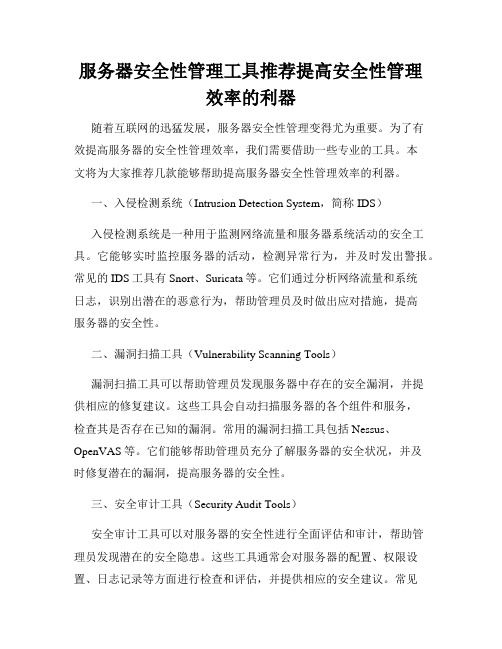
服务器安全性管理工具推荐提高安全性管理效率的利器随着互联网的迅猛发展,服务器安全性管理变得尤为重要。
为了有效提高服务器的安全性管理效率,我们需要借助一些专业的工具。
本文将为大家推荐几款能够帮助提高服务器安全性管理效率的利器。
一、入侵检测系统(Intrusion Detection System,简称IDS)入侵检测系统是一种用于监测网络流量和服务器系统活动的安全工具。
它能够实时监控服务器的活动,检测异常行为,并及时发出警报。
常见的IDS工具有Snort、Suricata等。
它们通过分析网络流量和系统日志,识别出潜在的恶意行为,帮助管理员及时做出应对措施,提高服务器的安全性。
二、漏洞扫描工具(Vulnerability Scanning Tools)漏洞扫描工具可以帮助管理员发现服务器中存在的安全漏洞,并提供相应的修复建议。
这些工具会自动扫描服务器的各个组件和服务,检查其是否存在已知的漏洞。
常用的漏洞扫描工具包括Nessus、OpenVAS等。
它们能够帮助管理员充分了解服务器的安全状况,并及时修复潜在的漏洞,提高服务器的安全性。
三、安全审计工具(Security Audit Tools)安全审计工具可以对服务器的安全性进行全面评估和审计,帮助管理员发现潜在的安全隐患。
这些工具通常会对服务器的配置、权限设置、日志记录等方面进行检查和评估,并提供相应的安全建议。
常见的安全审计工具有OpenSCAP、Lynis等。
它们能够帮助管理员全面了解服务器的安全状况,并及时采取相应的措施,提高服务器的安全性。
四、安全日志管理工具(Security Log Management Tools)安全日志管理工具可以帮助管理员对服务器的安全日志进行集中管理和分析,及时发现异常行为。
这些工具能够自动收集、存储和分析服务器产生的安全日志信息,并提供相应的报告和警报。
常用的安全日志管理工具有Elasticsearch、Splunk等。
Windows 7 默认服务启动对照表
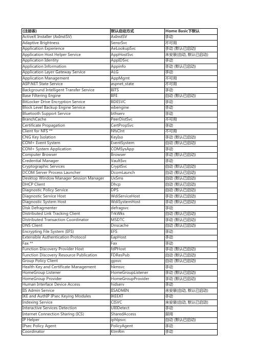
Remote Desktop Configuration ** Remote Desktop Services Remote Desktop Services UserMode Port Redirector Remote Procedure Call (RPC) Remote Procedure Call (RPC) Locator Remote Registry RIP Listener ** Routing and Remote Access RPC Endpoint Mapper SeaPort *** Secondary Logon Secure Socket Tunneling Protocol Service Security Accounts Manager Security Center Server Shell Hardware Detection Simple TCP/IP Services ** Smart Card Smart Card Removal Policy SNMP Service ** SNMP Trap Software Protection SPP Notification Service SSDP Discovery Storage Service Superfetch System Event Notification Service Tablet PC Input Service Task Scheduler TCP/IP NetBIOS Helper Telephony Telnet ** Themes Thread Ordering Server TPM Base Services UPnP Device Host User Profile Service Virtual Disk Volume Shadow Copy Web Management Service ** WebClient Windows Audio Windows Audio Endpoint Builder Windows Backup
网络智能化项目运维管理模板项目验收交维方案

项目交维方案项目组20 目录一、项目背景二、系统架构2.1、网络拓扑结构以2台交换机网络核心交换,接入2台负载均衡、刀片服务器,磁盘阵列;刀片服务器通过光纤交换机连接磁盘阵列进行数据交换,应用接入访问经过负载均衡实现资源平衡调度2.2、应用部署结构以统一门户为集中展现,数据中心为存储承载,消息中间件负载数据推送,开发实现并贯通内部管理系统、业务管理系统、基础服务平台整个生产环境划分了5个区,服务器总计31台(含两台小型机),具体如下:三、环境配置说明3.1、硬件设备分配平台基础硬件主要包含:刀片服务器:18台,刀箱2台,交换机2台,磁盘阵列1台,光纤交换机2台,备份磁带库1台,负载均衡2台3.2、网络地址分配地址主要包含:设备互联地址、设备管理地址、业务生产地址。
设备互联地址:设备互连地址使用10.154.30.0网段。
设备管理地址:三层设备地址用于路由域中设备标识(),同时作为网络管理地址。
业务生产地址:3.3、服务器资源分配A、生产环境:14块片集群,通过管理分配使用;2台小机承载数据库应用B、测试开发:3块刀片单独管理分配使用C、备份服务:1块刀片安装备份操作系统及应用3.4、虚拟化资源分配3.5、存储资源分配裸容量18T,经过5格式化后可用容量16T3.6、网络策略配置说明S9306核心层交换机1台。
四、应用部署说明4.1应用系统架构基础设施架构确定了支持数据体系架构和概念应用架构(支持业务需求)所需的技术基础设施组件。
基础设施体系架构定义功能级的架构组件。
一个完整的基础设施体系架构包括网络和通信架构的设计、服务器的配置等4.2系统部署细节4.2.1应用程序安装目录综合信息平台所有业务系统安装详细目录及启动脚本如下表格所示:地址应用名启动脚本主要程序目录4.2.2应用系统日志主要包含日志用途,目录,文件名,文件类型,清理日期等日志类型:错误日志、应用日志、搜索、访问、审计、安全、日常输出日志等日志(错误、应用、搜索):增长量20天清理日志:每周访问日志:增长量50天清理日志:每10天日志(中间件访问、审计、日常输出、安全):增长量100天清理日志:每周五、账号管理说明5.1、硬件管理端口及口令5.2、主机及数据库口令各主机目前对应主机名账号信息如下:目前使用的数据库有两种类型,分别为:和2,具体的数据库实例名及权限如下:六、后期维护说明6.1、虚拟机检查要求检查周期:每日三次检查对象:使用率,内存使用率,缓存,文件系统等判断依据:1、当、内存使用率超过相应阀值,需排查分析,以免使用或内存使用率过高导致系统性能下降;2、对文件系统磁盘使用空间剩余量检测,最大挂载次数,数据完整性自检等具体如下(为例):6.2.1、操作系统检查6.6.2、性能检查6.6.3、安全检查6.2、网络维护要求作为综合管理信息平台业务承载的基础,网络维护是日常维护作业中不可缺少的一部分,本期平台网络设备均采用双机热备(含两台6506核心交换机,两台博科磁盘阵列光纤交换机和两台负载均衡),可有效防止设备故障导致的系统瘫痪。
- 1、下载文档前请自行甄别文档内容的完整性,平台不提供额外的编辑、内容补充、找答案等附加服务。
- 2、"仅部分预览"的文档,不可在线预览部分如存在完整性等问题,可反馈申请退款(可完整预览的文档不适用该条件!)。
- 3、如文档侵犯您的权益,请联系客服反馈,我们会尽快为您处理(人工客服工作时间:9:00-18:30)。
信息---SAP SD
标准业务蓝图流程
●流程名称:可用性检查
●流程编号:SD_SSP_015
●发布日期:2009-3-5
●版本: V2.0
修改历史
目录
1.1 业务场景 (4)
1.2 目标/宗旨 (4)
1.3 流程概述 (4)
1.4 SAP 流程图 (4)
1.5 流程描述 (5)
1.6 系统单据/配套报表 (5)
1.7 特殊情况说明 (6)
1.8 配置测试要点 (6)
1.9 系统增强(USER EXIT) (6)
1.1 业务场景
在日常销售业务中,开具提货提单时,需检查库存情况,如果库存不够,则不能开具提单;同时对于已开具的提单,系统能够实现库存的预留。
1.2 目标/宗旨
可用性检查流程在销售发运业务提单环节建立库存可用性控制体系,可以在库存不足的情况通过可用性检查流程控制提单的开具;对已经开具的提单,可以通过可用性检查预留库存,防止系统的库存被其他提单占用、发货。
1.3 流程概述
1)物料(物料销售组织视图)中配置10和02两个检查组,10是SD进行可用性检查;02
是不进行可用性检查。
2)10和02对于PP的设置一样。
3)10的话,在订单中传输需求,但是不进行可用性检查
4)10的话,在提单中传需需求并进行可用性检查,如果可用量不够,不予保存。
5)可用量= 目前的库存–已经开出的提单没有发货的。
6)物料中配置10和02两个检查组,10是SD进行可用性检查,02是不进行可用性检查,
一般情况下散装物料使用02检查组,包装物料使用10检查组。
7)检查组10和02和PP模块相应检查组的设置一样。
8)检查组10控制在创建订单时不进行可用性检查;在创建提单时进行可用性检查,如果
可用量不够,提单不能保存。
9)提单可用量= 目前系统的库存–已开提单没有发货的库存量。
10)可用性检查功能由工厂根据自己的需求选择使用。
为营销公司供货的工厂必须使用可用
性检查。
11)由于会存在为周六周日提前开提单的情况,可以通过修改提单抬头-处理的交货日期为
需要物料可用的实际日期再点下排产。
这样如果物料可用日期在当天加上物料中补货提前期之后,则系统默认可用量为无限。
即让系统去未来确认可用量,而不是当天。
1.4 SAP 流程图
确定物料可
用性检查组
创建提单
拆分提单
检查库存占用情况
手工释放提单
销售后继流程
1.5 流程描述
1.可用性检查流程
1.6 系统单据/配套报表
1.系统单据
VL01N 销售提单
2.配套报表
ZSD508 库存概览报表
CO09 可用性总览报表
MMBE、MB51、MB52
15.3 流程适用范围
本流程适用于集团内各个行业
1.7 特殊情况说明
无
1.8 配置测试要点
1.物料可用性检查组为02的物料,创建订单、提单是否进行可用性检查。
2.物料可用性检查组为10的物料,创建订单时是否控可用性、创建提单时是否进行可用性检查。
3、当进行可用性检查时,已占用的库存是否只考虑提单的数量,可用量计算逻辑是否正确。
1.9 系统增强(USER EXIT)
无。