pc104规范
PC104总线引脚定义

PC/104总线是嵌入式PC机所用的总线标准.有两个总线插头.其中P1有64个引脚, P2有40个引脚共有104个引脚,这也是PC/104名称的由来.PC104有两个版本,8位和16位,分别与PC和PC/AT 相对应。
PC104PLUS 则与PCI总线相对应.PC/104模块本质上就是尺寸缩小为3.8英寸3.9英寸的ISA总线板卡。
它的总线与ISA在IEEE-P996中定义基本相同。
具有16位数据宽度,最高工作频率为8MHz数据传输速率达到8MB/s,地址线24条,可寻访16M字节地址单元。
所有PC/104总线信号定义和功能与它们在ISA总线相应部分是完全相同的。
104根线分为5类:地址线、数据线、控制线、时钟线、电源线。
简要介绍如下:(1)地址线SA0~SA19和LA17~LA23SA0~SA19是可锁存的地址信号,LA17~LA23是非锁存信号由于没有锁存延迟因而给外设插板提供了一条快捷途径。
SA0~SA19加上LA17~LA23可实现16MB空间寻址(其中SA17~SA19和LA17~LA19是重复的)(2)数据线数据线SD0~SD7和SD8~SD15其中SD0~SD7位为低8位数据,SD8~SD15为高8位数据(3)控制线AEN:地址允许信号,输出线,高电平有效。
AEN=1,表明处于DMA控制周期;AEN=0,表示非DMA周期。
此信号用来在DMA期间禁止I/O端口的地址译码。
BALE:允许地址锁存,输出线。
这信号由总线控制器8288提供,作为CPU地址的有效标志。
当BALE为高电平时将SA0~SA19接到系统总线。
其下降沿用来锁存SA0~SA19IOR:I/O读命令,输出线,低电平有效。
用来把选中的I/O设备的数据读到数据总线上,在CPU启动的周期通过地址线选择I/O。
在DMA周期,I/O设备由DACK选择IOW:I/O写命令,输出线,低电平有效,用来把数据总线上的数据写入被选中的I/O端口SMEMR和SMEMW:存储器读/写命令,低电平有效,用于对SA0~SA19这20位地址寻址的1MB内存的读/写操作MEMR和MEMW:低电平有效,存储器读/写命令,用于对24位地址线全部存储空间读/写操作MEMCS16 和I/OCS16:它们是存储器16位片选信号和I/O16位片选信号,分别指明当前数据传送是16位存储器周期和16位I/O周期SBHE:总线高字节允许信号,该信号有效时表示数据总线上传,送的是高位字节数据IRQ3~IRQ7,IRQ9,IRQ10~IRQ15用于作为来自外部设备的中断请求输入线分别连在主片8259A和从片8259A中断控制器的输入端。
广州周立功单片机 PC104-CAN 单路非智能 CAN 接口卡 说明书 V1.0
V CA N_H
屏蔽线
红色 P.M.S#207C 白色 EIA935A 线缆限制
CAN_L V
蓝色 P.M.S.#297C 黑色 P.M.S.#426C
图 3.2 OPEN5 连接器
3.5. CAN 总线连接
终端电阻
Node #1
Node #2 ........ Node #n
CAN_H
CAN_L
图 3.3 CAN 网络结构
参考相关接口函数说明。
3.4. DB9 针型插座引脚定义
PC104-CAN 非智能 CAN 接口卡只有一个 CAN 通道,通过 DB9 针型插座 CZ1 与实际的 CAN 网络进 行连接。CZ1 的管脚信号定义如表 三-1 所示。管脚定义符合 DeviceNet 和 CANopen 标准。
广州周立功单片机发展有限公司
6.1.
保修期.......................................................................................................................................... 20
6.2.
四 设备安装 .......................................................................................................................................................... 6
PHILIPS PCA82C250;
z 数据传送速率: CAN 控制器数据传送速率可编程,最高达 1Mbit/s;
什么是PC104
什么是PC/104PC/104(pc104)是一种嵌入式的总线规范。
提到PC/104,我们就必须提及著名的ISA总线,因为这二者之间有着天然的联系。
1981年,美国IBM公司制造出了世界上第一台个人计算机——PC机,与此同时,IBM 提出了PC总线(PC/XT总线),这是一种8位总线。
1984年,提出PC/AT总线,这是一种16位总线。
而为了开发与IBMPC兼容的外围设备,行业内便逐渐确立了以IBMPC总线规范为基础的ISA(工业标准架构:IndustryStandardArchitecture)总线。
1987年IEEE正式制订了ISA总线标准。
PC/104(pc104)是ISA(IEEE-996)标准的延伸。
1992年PC/104作为基本文件被采纳,叫做IEEE-P996.1兼容PC嵌入式模块标准。
PC/104是一种专门为嵌入式控制而定义的工业控制总线。
IEEE-P996是ISA工业总线规范,IEEE协会将它定义IEEE-P996.1,PC/104实质上就是一种紧凑型的IEEE-P996,其信号定义和PC/AT基本一致,但电气和机械规范却完全不同,是一种优化的、小型、堆栈式结构的嵌入式控制系统。
其小型化的尺寸(90x96mm),极低的功耗(典型模块为1-2瓦)和堆栈的总线形式(决定了其高可靠性),受到了众多从事嵌入式产品生产厂商的欢迎,在嵌入式系统领域逐渐流行开来。
截止目前,全世界已有200多家厂商在生产和销售符合PC/104规范的嵌入式板卡。
实际上,早在PC/104规范诞生之前,1987年就产生了世界上第一块PC/104板卡,由于其固有的优点,在国际上制订统一的规范之前,一直有许多厂商在生产类似的嵌入式板卡。
到了1992年,由业界著名的RTD公司和AM PRO公司等12家从事嵌入式系统开发的厂商发起,组建了国际PC/104协会,得到了全世界众多厂商纷纷响应,从此PC/104技术的发展走上了康庄大道。
4 SY 1002.1标准讲义--术语

组织应建立、实施、保持和持续改进健康、安全与环境
管理体系,确定如何实现这些要求,并形成文件。第5章描
述了健康、安全与环境管理体系的要求。
组织应界定健康、安全与环境管理体系的范围,并形成 文件。
23
4 总要求
管理评审 推进力
总体原则 健康、安全 与 环境方针
策划
检查和 纠正措 施 保障
领导 和承诺 前提条件
方建立、实施、保持和持续改进健康、安全与环境管理体系。
组织依据本标准的要求建立、实施、保持和改进健康、 安全与环境管理体系时,应充分考虑组织的健康、安全与环 境方针、活动性质、运行的风险与复杂性等因素。
9
2、规范性引用文件
下列文件中的条款通过本标准的引用而成为本标准的条款。 凡是注日期的引用文件,其随后所有的修改单(不包括勘误 的内容)或修订版均不适用于本标准,然而,鼓励根据本标
失、工作环境破坏、有害的环境影响或这些情况的组合。 3.6 纠正 corrective
消除已发现的不符合。 3.7 纠正措施 corrective action
为消除已发现的不符合的原因所采取的措施。
3.26预防措施 preventive action
为消除潜在不符合原因所采取的措施。
22
4 总要求
注:在许多情况下,独立性可通过与所审核活动无责任关系来体现。
3.3审核员
auditor
经过培训,并取得相应资质,有能力实施审核的人员。
21
3、术语和定义
3.21不符合 non-conformance 任何与工作标准、惯例、程序、法规、管理体系绩效等
的偏离,其结果能够直接或间接导致伤害或疾病、财产损
11
3、术语和定义
ISA(PC104)总线规范
ISA(PC104)总线规范ISA(PC/104) 总线信号时序简介SBS Science & Technology Co., Ltd.APPN-002ISA(PC/104)总线信号时序简介目录1.0 ISA概况2.0 ISA文献2.1 ISA规范 2.2 ISA书籍3.0 ISA结构形式4.0 PC/104结构形式5.0 ISA信号描述6.0 ISA 时序图7.0 ISA信号用法8.0 ISA连接器引脚9.0 PC/104总线连接引脚盛博科技1APPN-002ISA(PC/104)总线信号时序简介1.0 ISA 概况ISA总线即工业标准结构 Industry Standard Architecture 十世纪八十年代早期IBM在佛罗里达州Boca Raton研发实验室出的个人电脑其中包括了8位ISA总线 1984年最早起源于二 IBM于1981年推IBM推出了PC-AT 这是第一个全面实现16位结构的ISA总线IBM最初命名的AT总线首先被记录于IBM出版的 The PC-AT TechnicalReference 上此书包括了图表和BIOS清单这样类似于康柏的其它公司很容易就生产出了IBM兼容的产品由于IBM将AT总线”作为一项商标进行保护其它生产兼容IBM产品的公司就不能使用 AT总线这个名称结果人们在行业中创造了 ISA 并将其作为这种总线的新名称这个名称最后被包括IBM在内的所有公司采用尽管 The PC-AT Technical Reference 包含了详细的图表和BIOS清单但其因未包含严格的时序规范及其它必要条件而未成为一个很好的总线规范结果对ISA各种各样的实现造成了一些产品之间的兼容性问题的问题迄今为止渐渐形成了许多ISA总线规范但是不幸的是为了减轻因兼容造成这些规范也不尽相同没有产生出一个完全统一的ISA总线规范2.0 ISA 文献2.1 ISA 规范有关ISA总线规范的文档有如下几篇 EISA Specification, Version 3.12――这篇文档包括ISA总线规范并规定了扩展工业标准结构定义了ISA总线上32位扩展 IEEE Draft Standard P996 这篇文档描写了标准PC类系统的机械和电子规范通过/doc/4d9951778.html,/.付费可以向IEEE订购PS/2 Technical Reference 这篇来自IBM的文档内容包括在一些IBM 计算机PS/2线上使用ISA总线的信号定义和时序图2.2 ISA书籍两本对ISA总线进行了详细描述的书是 ISA & EISA Theory and Operation, by Edward Solari. (Annabooks) (ISBN 0-929392-15-9) ISA System Architecture, by Don Anderson and Tom Shanley. (MindShare) (ISBN 0-201-40996-8)盛博科技2APPN-002ISA(PC/104)总线信号时序简介3.0 ISA结构形式8 位卡:(At the card)(At the computer)16 位卡:(At the card)(At the computer)盛博科技3APPN-002ISA(PC/104)总线信号时序简介4.0 PC/104结构形式与ISA板不同义相同PC/104 8位/16位总线模块具有同样尺寸全为地 Gnd与ISA板总线信号定但多A32/B32;C0/D0;C19/D19引脚盛博科技4APPN-002ISA(PC/104)总线信号时序简介5.0 ISA 信号描述SA19-SA0System Address 地址位19:0用于对系统中内存和I/O设备的寻址内存寻址时使用SA19:SA0配合LA23:LA17 能寻址多达16兆的内存低16位,可以用来定位64K的I/O地址号在BALE为高时有效持有效 SA19是最高位 I/O寻址中只使用地址信SA0为最低位而由BALE的下降沿锁定通过读或写命令使信号保但也可以由ISA这些信号通常由系统微处理器或DMA控制器驱动扩展板的Bus Master 来取得ISA总线的控制权LA23-LA17Unlatched Address 23:17位是系统中内存地址址多达16兆的内存它们和SA19:SA0可以共同寻由于它们是非锁存的当BALE为高时这些信号才有效故在整个总线周期中它们并不总是保持有效状态用BALE下降沿锁存这些信号的译码AENAddress Enable 用于DMA传送过程中关闭总线系统微处理器和其它设备的传送通道制当AEN有效时总线上的地址数据和读写信号由DMA控制器控以防止DMA周期中出现不正确ISA扩展板的片选译码应包含AEN信号的片选BALEBuffered Address Latch Enable 用来锁存LA23:LA17信号或者译码这些信号 BALE下降沿用于锁存LA23:LA17 在DMA周期中BALE 被强制为高此信号与AEN并用时表明一个有效的微处理器或DMA地址CLKSystem Clock 是一个自行运转的时钟它的频率一般在7MHz到10MHz之间系统时钟在一些ISA板的应用中保证与该频率值在ISA 标准中并未严格定义系统微处理器的同步工作盛博科技5APPN-002ISA(PC/104)总线信号时序简介SD15 - SD0System Data SD15:SD0是ISA总线上的数据总线最低位 8位设备的数据传送通过SD7:SD0来完成其中SD15是最高位SD0是SD15:SD0则用于传送16位设备的数据当16位设备向8位设备传送数据时需将16位信号转换成两个8位周期通过SD7:SD0来进行传送-DACK0 to -DACK3 and -DACK5 to -DACK7DMA Acknowledge 0:3和5:7分别被用来确认DRQ0:DRQ3和DRQ5:DRQ7的 DMA请求DRQ0 to DRQ3 and DRQ5 to DRQ7DMA Requests 用于ISA板向DMA控制器提出服务请求或者Bus Master设备申请总线控制权的请求多个DMA请求可能同时断定有效发出请求的设备必须保持请求信号有效直到系统板发出相应的DACK信号-I/O CH CKI/O Channel Check I/O CH CK由ISA板生成进而引发非屏蔽中断时表明发现了不可恢复的错误当它有效I/O CH RDYI/O Channel Ready 允许较慢速ISA板通过插入等待状态延长I/O或内存读写周期好 I/O CH RDY通常处于高以插入等待状态就绪 ISA板将I/O CH RDY拉低未准备使用I/O CH RDY插入等待状态的设备需可以完成读写周期时地址译码和读/写信号有效后立即使I/O CH RDY信号为低当设备释放 I/O CH RDY回高-IORI/O Read 线上由总线控制设备驱动并且指令所选的I/O设备将数据读到数据总-IOWI/O Write 由总线控制设备驱动指令所选的I/O设备从数据总线上获取数据盛博科技6APPN-002ISA(PC/104)总线信号时序简介IRQ3 to IRQ7 and IRQ9 to IRQ12 and IRQ14 to IRQ15Interrupt Requests 向系统微处理器发出信号提示来自ISA板的请求当IRQ 线由低向高跳变时产生中断请求请求必须一直保持为高直到CPU通过其中断服务程序确认了这个请求请求有不同的优先权来自IRQ9:IRQ12 而来自IRQ3:IRQ 7IRQ14 :IRQ15的请求优先被处理的请求较后处理 IRQ7优先级最低IRQ9优先级最高-SMEMRSystem Memory Read 指令一个所选定的Memory设备将数据送到数据总线该信号仅在对1M以内的Memory空间读时才有效SMEMR来源于MEMR及低于1兆的存储译码-SMEMWSystem Memory Write 指令将当前数据总线上的数据写入一个所选定的 Memory设备该信号仅在对1M以内的Memory空间写时才有效 SMEMR来源于MEMR及低于1兆的存储译码-MEMRMemory Read 指令将一个所选定的Memory设备数据读出送到数据总线它在整个Memory存储读周期中都有效-MEMWMemory Write 指令将当前数据总线上的数据存储到一个所选定的Memory设备中它在整个Memory存储写周期中都有效-REFRESHMemory Refresh 该信号为低时表明正在进行内存刷新操作OSCOscillator 是一个时间段为70毫微秒的时钟(14.31818 MHz) 该信号与系统时钟不同步盛博科技7APPN-002ISA(PC/104)总线信号时序简介RESET DRVReset Drive在电源开启或系统复位时来复位或初始化系统逻辑高电平有效TCTerminal Count 在DMA通道操作中当计数完成时产生的终端计数信号-MASTERMaster 和DRQ线一起获得ISA板上ISA总线的控制权后权设备将MASTER信号拉低在此状态下使得其获得系统地址当接收到一个DACK 数据和控制线的控制在读/设备将在驱动地址和数据线之前等待一个时钟周期写命令之前等待两个时钟周期-MEM CS16Memory Chip Select 16 ISA板将该信号拉低以指示这是一个16位的Memory读写操作它由LA23:LA17地址线译码来驱动-I/O CS16I/O Chip Select 16 I/O设备将该信号拉低以指示这是一个16位的Memory读写操作它由SA15:SA0地址线译码来驱动-0WSZero Wait State 由一个总线从设备驱动使其拉低状态即可完成一个总线周期由地址译码产生说明不插入任何额外等待-OWS 完成一个无需等待的16位Memory周期-SBHESystem Byte High Enable 该信号为低时表明数据在数据总线高位部分传送(D15 至 D8)盛博科技8APPN-002ISA(PC/104)总线信号时序简介6.0 ISA总线时序图8位 I/O 总线周期BALE SA(15:0) -SBHE -IOR/W SD(7:0) (READ) SD(7:0) (WRITE) I/OCHRDY ________ __| |_________________________________________ _ ______________________________________________ __ _><______________________________________________><________________ _______ |______________________________| _____________ -------------------------------------<_____________>__________________________________ ----------------<__________________________________>__________________ _ _ _ _ _ _ _ _ _ _ _ _ _________ |________________________|8 位 Memory 总线循环_____ ________| |______________________________________ _ ________________ ________________________________ LA(23:17) _><________________><________________________________ _______ ________________________________________ __ SA(19:0) _______><________________________________________><________________ _______ -MEMR/W |______________________________| _____________ SD(7:0) -------------------------------------<_____________>(READ) __________________________________ SD(7:0) ----------------<__________________________________>(WRITE)__________________ _ _ _ _ _ _ _ _ _ _ _ _ _________ I/OCHRDY |________________________| BALE盛博科技9APPN-002ISA(PC/104)总线信号时序简介16 位 I/O 总线周期________ BALE SA(15:0) -IOCS16 -IOR/W SD(15:0) (READ) SD(15:0) (WRITE) I/OCHRDY ______________| |_____________________________ _____________ __________________________________ __ _____________><__________________________________><___________________ ___ |_______________________________| _____________________ ______ |________________________| __________________ -----------------------------<__________________>---________________________ -----------------------<________________________>---_______________________ _ _ _ _ _ _ _ _ _ _ ______ |___________________|16 位 Memory 总线周期BALE1 个或多个等待状态______ _________________| |____________________________ ___ ________________________ ______________________ LA(23:17) ___><________________________><______________________________________ ________________________________ _ SA(19:0) ________________><________________________________><_ _______ ______________________ -MEMCS16 |______________________| ________________________ ______ -MEMR/W |_____________________| _______________ SD(15:0) --------------------------------<_______________>---(READ) _____________________ SD(15:0) --------------------------<_____________________>---(WRITE)__________________________ _ _ _ _ _ _ _ _ __________ I/OCHRDY |_______________|盛博科技10APPN-002ISA(PC/104)总线信号时序简介6 位 Memory 总线周期BALE0 等待状态______ _________________| |____________________________ ___ ________________________ ______________________ LA(23:17) ___><________________________><______________________________________ _________________________ ________ SA(19:0) ________________><_________________________><________ _______ ______________________ -MEMCS16 |______________________| _________________________ ______________________ -0WS |____| ________________________ ________________ -MEMR/W |___________| ______ SD(15:0) --------------------------------<______>------------(READ) ____________ SD(15:0) --------------------------<____________>------------(WRITE)DMA 读DRQ(n) -DACK(n) AEN,BALE SA(15:0) -SBHE ______________ __| |___________________________________ _______________ __________ |__________________________| ____________________________________ ________| |_______ _______________ ___________________________ _______ _______________><___________________________><_______________________ ________________________ _________ SA(19:16) ________________><________________________><_________ LA(23:17) ____________________ __________ -MEMR |_____________________| ____________ SD(15:0) -------------------------------<____________>-------______________________ ___________ -IOW |__________________| __________ TC _______________________________| |__________ ________________________ _____________________ I/OCHRDY |______|盛博科技11APPN-002ISA(PC/104)总线信号时序简介DMA 写DRQ(n) -DACK(n) AEN,BALE SA(15:0) -SBHE ______________ __| |___________________________________ _______________ __________ |__________________________| ____________________________________ ________| |_______ _______________ ___________________________ _______ _______________><___________________________><_______________________ ________________________ _________ SA(19:16) ________________><________________________><_________ LA(23:17) ____________________ __________ -IOR |_____________________| ____________ SD(15:0) -------------------------------<____________>-------______________________ ___________ -MEMW |__________________| __________ TC _______________________________| |__________ ________________________ _____________________ I/OCHRDY |______| Bus Master 周期DRQ(n) -DACK(n) -MASTER AEN BALE SA(19:0) -SBHE ___________________________________ __| |______________ _______________ __________ |__________________________| __________________ _______ |__________________________| __________________ _______ ________| |__________________________| |_ _____________________________________________________ ________| |_ ________________________ ___________ ______________ ________________________><___________><_______________ ________________________ ___________ ______________ LA(23:17) ________________________><___________><___________________________________________ _________________ -IOR,-IOW |_____| -MEMR,-MEMW _____ SD(15:0) -------------------------------<_____>---------------盛博科技12APPN-002ISA(PC/104)总线信号时序简介内存刷新周期_______________ -REFRESH SA(9:0) -SMEMR I/OCHRDY _______________ |_____________________| _________________ ____________ _____________________________________><____________><__________________________________________ ________________ |_____________| _________________________ _ _ _ _ ___________________ |_______|7.0 ISA信号用法图例 I/O = 输入/输出 I = 输入 O = 输出 = 不需要的信号里表明这个信号是可选信号 I/O 出现在括号下表是 ISA 系统板上典型的信号使用情况Signal Name System Board Usage AEN BALE CLK -DACK DRQ -IO CS16 -I/O CH CK I/O CH RDY -IOR -IOW IRQ LA -MASTER O O O O I I I I/O I/O I/O I I/O ISignal Name -MEM CS16 -MEMR -MEMW OSC -REFRESH RESET DRV SA SD -SBHE -SMEMR -SMEMW TC -0WS System Board Usage I/O I/O I/O O I/O O I/O I/O I/O I/O I/O I/O I盛博科技13APPN-002ISA(PC/104)总线信号时序简介下表是 ISA 扩展板上典型的信号使用的情况Signal Name AEN BALE CLK -DACK DRQ -IO CS16 -I/O CH CK I/O CH DY -IOR -IOW IRQ LA(23:17) -MASTER -MEM CS16 -MEMR -MEMW OSC -REFRESH RESET DRV SA(16:0) SA(19:17) SD(7:0) SD(15:8) -SBHE -SMEMR -SMEMW TC -0WS ISA Bus Master (I) I O I (O) I O O (O) O O I O O (I) (O) I O I/O I/O O ISA 16-bit Mem Slave I (I) (O) (O) (O) I 0 I I (I) I I I (I) I/O I/O I (O) ISA 16-bit I/O Slave I (I) O (O) (O) I I (O) (I) I I I/O I/O I ISA 8-bit Mem Slave (I) (I) (O) (O) (O) (I) (I) (I) (I) I I I (I) I/O I I (O) ISA 8-bit I/O Slave I (I) (O) (O) I I (O) (I) I I I/O (O) ISA DMA Device (I) I O (O) I I (O) (I) I I/O (I/O) (I) -盛博科技14APPN-002ISA(PC/104)总线信号时序简介8.0 ISA 连接引脚Signal Name Pin Pin Signal Name Ground +5 V dc IRQ 9 -5 V dc DRQ2 -12 V dc -0WS +12 V dc Ground -SMEMW -SMEMR -IOW -IOR -DACK3 DRQ3 -DACK1 DRQ1 CLK IRQ7 IRQ6 IRQ5 IRQ4 IRQ3 -DACK2 TC BALE +5 V dc OSC Ground B1 A1 -I/O CH CK SD7 SD6 SD5 SD4 SD3 SD2 SD1 SD0 AEN SA19 SA18 SA17 SA16 SA15 SA14 SA13 SA12 SA11 SA10 SA9 SA8 SA7 SA6 SA5 SA4 SA3 SA2 SA1 SA0 B3 A3 B4 A4 B5 A5 B6 A6 B7 A7 B8 A8 B9 A9 B11 A11 B12 A12 B13 A13 B14 A14 B15 A15 B16 A16 B17 A17 B18 A18 B20 A20 B21 A21 B22 A22 B23 A23 B24 A24 B25 A25 B26 A26 B27 A27 B28 A28 B29 A29 B30 A30 B31 A31 Key RESET DRV B2 A2Signal Name Pin Pin Signal Name -MEM CS16 D1 C1 -IO CS16 IRQ10 IRQ11 IRQ12 IRQ15 IRQ14 -DACK0 DRQ0 -DACK5DRQ5 -DACK6 DRQ6 -DACK7 DRQ7 +5 V dc Ground D2 C2 D3 C3 D4 C4 D5 C5 D6 C6 D7 C7 D8 C8 D9 C9 D10 C10 D11 C11 D12 C12 D13 C13 D14 C14 D15 C15 D16 C16 D18 C18 -SBHE LA23 LA22 LA21 LA20 LA19 LA18 LA17 -MEMR -MEMW SD08 SD09 SD10 SD11 SD12 SD13 SD14 SD15B10 A10 I/O CH RDY-MASTER D17 C17-REFRESH B19 A19盛博科技15APPN-002ISA(PC/104)总线信号时序简介9.0 PC/104总线引脚引脚A1 A2 A3 A4 A5 A6 A7 A8 A9 A10 A11 A12 A13 A14 A15 A16 A17 A18 A19 A20 A21 A22 A23 A24 A25 A26 A27 A28 A29 A30 A31 A32信号名-IOCHCK SD7 SD6 SD5 SD4 SD3 SD2 SD1 SD0 IOCHRDY AEN SA19 SA18 SA17 SA16 SA15 SA14 SA13 SA12 SA11 SA10 SA9 SA8 SA7 SA6 SA5 SA4 SA3 SA2 SA1 SA0 GND用途Bus NMI input Data Bit 7 Data Bit 6 Data Bit 5 Data Bit 4 Data Bit 3 Data Bit 2 Data Bit 1 Data Bit 0 Processor Ready Ctrl Address Enable Address Bit 19 Address Bit 18 Address Bit 17 Address Bit 16 Address Bit 15 Address Bit 14 Address Bit 13 Address Bit 12 Address Bit 11 Address Bit 10 Address Bit 9 Address Bit 8 Address Bit 7 Address Bit 6 Address Bit 5 Address Bit 4 Address Bit 3 Address Bit 2 Address Bit 1 Address Bit 0 Ground P1AIn/OutIN I/O I/O I/O I/O I/O I/O I/O I/O IN I/O I/O I/O I/O I/O I/O I/O I/O I/O I/O I/O I/O I/O I/O I/O I/O I/O I/O I/O I/O I/O N/A PC/104 总线接口盛博科技16APPN-002ISA(PC/104)总线信号时序简介引脚B1 B2 B3 B4 B5 B6 B7 B8 B9 B10 B11 B12 B13 B14 B15 B16 B17 B18 B19 B20 B21 B22 B23 B24 B25 B26 B27 B28 B29 B30 B31 B32信号名GND RESET +5V IRQ9 -5V DRQ2 -12V ENDXFR +12V N/A -SMEMW -SMEMR -IOW -IOR -DACK3 DRQ3 -DACK1 DRQ1 -REFRESH SYSCLK IRQ7 IRQ6 IRQ5 IRQ4 IRQ3 -DACK2 T/C BALE +5V OSC GND GND用途Ground System Reset +5v Power Int Request 9 -5v Power DMA Request 2 -12v Power Zero wait state +12v Power Key Pin Mem Wrt, Io 1M Mem Rd, Io 1M I/O Write I/O read DMA Ack 3 DMA request 3 DMA Ack 1 DMA request 1 Memory Refresh Sys Clock Int Request 7 Int Request 6 Int Request 5 Int Request 4 Int Request 3 DMA Ack 2 Terminal Count Addrs Latch En +5v Power 14.3MHz Clk Ground Ground P1BIn/OutN/A OUT N/A IN N/A IN N/A IN N/A N/A I/O I/O I/O I/O OUT IN OUT IN I/O OUT IN IN IN IN IN OUT OUT OUT N/A OUT N/A N/APC/104 总线接口盛博科技17APPN-002ISA(PC/104)总线信号时序简介引脚C0 C1 C2 C3 C4 C5 C6 C7 C8 C9 C10 C11 C12 C13 C14 C15 C16 C17 C18 C19信号名GND SBHE LA23 LA22 LA21 LA20 LA19 LA18 LA17 -MEMR -MEMW SD8 SD9 SD10 SD11 SD12 SD13 SD14 SD15 Key 用途Ground Bus High Enable Address bit 23 Address bit 22 Address bit 21 Address bit 20 Address bit 19 Address bit 18 Address bit 17 Memory Read Memory Write Date Bit 8 Date Bit 9 Date Bit 10 Date Bit 11 Date Bit 12 Date Bit 13 Date Bit 14 Date Bit 15 Key Pin P2CIn/OutN/A I/O I/O I/O I/O I/O I/O I/O I/O I/O I/O I/O I/O I/O I/O I/O I/O I/O I/O N/APC/104 总线接口引脚D0 D1 D2 D3 D4 D5 D6 D7 D8 D9 D10 D11 D12 D13 D14 D15 D16 D17 D18 D19信号名GND -MEMCS16 -IOCS16 IRQ10 IRQ11 ** IRQ15 IRQ14 -DACK0 DRQ0 -DACK5 DRQ5 -DACK6 DRQ6 -DACK7 DRQ7 +5V -MASTER GND GND用途Ground 16-bit Mem Access 16-bit I/O Access Interrupt Request 10 Interrupt Request 11 Interrupt Request 15 Interrupt Request 14 DMA Acknowledge 0 DMA Request 0 DMA Acknowledge 5 DMA Request 5 DMA Acknowledge 6 DMA Request 6 DMA Acknowledge 7 DMA Request 7 +5V Power Bus Master Assert Ground Ground P2DIn/OutN/A IN IN IN IN IN IN OUT IN OUT IN OUT IN OUT IN N/A IN N/A N/APC/104 总线接口盛博科技18。
ISA(PC104)总线信号时序简介

ISA(PC/104) 总线信号时序简介SBS Science & Technology Co., Ltd.APPN-002ISA(PC/104)总线信号时序简介目录1.0 ISA概况 2.0 ISA文献2.1 ISA规范 2.2 ISA书籍3.0 ISA结构形式 4.0 PC/104结构形式 5.0 ISA信号描述 6.0 ISA时序图 7.0 ISA信号用法 8.0 ISA连接器引脚 9.0 PC/104总线连接引脚盛博科技1APPN-002ISA(PC/104)总线信号时序简介1.0 ISA 概况ISA总线 即工业标准结构 Industry Standard Architecture 十世纪八十年代早期IBM在佛罗里达州Boca Raton研发实验室 出的个人电脑 其中包括了8位ISA总线 1984年 最早起源于二 IBM于1981年推IBM推出了PC-AT 这是第一个全面实现16位结构的ISA总线 IBM最初命名的 AT总线 首先被记录于IBM出版的 The PC-AT TechnicalReference 上 此书包括了图表和BIOS清单 这样类似于康柏的其它公司很容易 就生产出了IBM兼容的产品 由于IBM将 AT总线”作为一项商标进行保护 其它生产兼容IBM产品的公司就不能使用 AT总线 这个名称 结果 人们在行业 中创造了 ISA 并将其作为这种总线的新名称 这个名称最后被包括IBM在内的所有公司采用 尽管 The PC-AT Technical Reference 包含了详细的图表和BIOS清单 但其 因未包含严格的时序 规范及其它必要条件而未成为一个很好的总线规范 结果 对ISA各种各样的实现造成了一些产品之间的兼容性问题 的问题 迄今为止 渐渐形成了许多ISA总线规范 但是不幸的是 为了减轻因兼容造成 这些规范也不尽相同没有产生出一个完全统一的ISA总线规范2.0 ISA 文献2.1 ISA 规范有关ISA总线规范的文档有如下几篇 EISA Specification, Version 3.12――这篇文档包括ISA总线规范 并规定了 扩展工业标准结构 定义了ISA总线上32位扩展 IEEE Draft Standard P996 这篇文档描写了标准PC类系统的机械和电 子规范 通过/.付费可以向IEEE订购 PS/2 Technical Reference 这篇来自IBM的文档内容包括在一些IBM计 算机PS/2线上使用ISA总线的信号定义和时序图2.2 ISA书籍两本对ISA总线进行了详细描述的书是 ISA & EISA Theory and Operation, by Edward Solari. (Annabooks) (ISBN 0-929392-15-9) ISA System Architecture, by Don Anderson and Tom Shanley. (MindShare) (ISBN 0-201-40996-8)盛博科技2APPN-002ISA(PC/104)总线信号时序简介3.0 ISA结构形式8 位卡:(At the card)(At the computer)16 位卡:(At the card)(At the computer)盛博科技3APPN-002ISA(PC/104)总线信号时序简介4.0 PC/104结构形式与ISA板不同 义相同PC/104 8位/16位总线模块具有同样尺寸 全为地 Gnd与ISA板总线信号定但多A32/B32;C0/D0;C19/D19引脚盛博科技4APPN-002ISA(PC/104)总线信号时序简介5.0 ISA 信号描述SA19-SA0System Address 地址位19:0用于对系统中内存和I/O设备的寻址 内存寻址时 使用SA19:SA0配合LA23:LA17 能寻址多达16兆的内存 低16位,可以用来定位64K的I/O地址 号在BALE为高时有效 持有效 SA19是最高位 I/O寻址中 只使用 地址信SA0为最低位而由BALE的下降沿锁定通过读或写命令使信号保 但也可以由ISA这些信号通常由系统微处理器或DMA控制器驱动扩展板的Bus Master 来取得ISA总线的控制权LA23-LA17Unlatched Address 23:17位是系统中内存地址 址多达16兆的内存 它们和SA19:SA0可以共同寻 由于它们是非锁存的 当BALE为高时这些信号才有效故在整个总线周期中它们并不总是保持有效状态 用BALE下降沿锁存这些信 号的译码AENAddress Enable 用于DMA传送过程中关闭总线系统微处理器和其它设备的 传送通道 制 当AEN有效时 总线上的地址 数据和读写信号由DMA控制器控 以防止DMA周期中出现不正确ISA扩展板的片选译码应包含AEN信号的片选BALEBuffered Address Latch Enable 用来锁存LA23:LA17信号或者译码这些信号 BALE下降沿用于锁存LA23:LA17 在DMA周期中BALE被强制为高 此信号 与AEN并用时表明一个有效的微处理器或DMA地址CLKSystem Clock 是一个自行运转的时钟 它的频率一般在7MHz到10MHz之间 系统时钟在一些ISA板的应用中保证与 该频率值在ISA标准中并未严格定义 系统微处理器的同步工作盛博科技5APPN-002ISA(PC/104)总线信号时序简介SD15 - SD0System Data SD15:SD0是ISA总线上的数据总线 最低位 8位设备的数据传送通过SD7:SD0来完成 其中SD15是最高位 SD0是 SD15:SD0则用于传送16位设备的数据 当16位设备向8位设备传送数据时 需将16位信号转换成两个8位 周期通过SD7:SD0来进行传送-DACK0 to -DACK3 and -DACK5 to -DACK7DMA Acknowledge 0:3和5:7分别被用来确认DRQ0:DRQ3和DRQ5:DRQ7的 DMA请求DRQ0 to DRQ3 and DRQ5 to DRQ7DMA Requests 用于ISA板向DMA控制器提出服务请求 或者Bus Master设备 申请总线控制权的请求 多个DMA请求可能同时断定有效 发出请求的设备必须保持请求信号有效直到系统板发出相应的DACK信号-I/O CH CKI/O Channel Check I/O CH CK由ISA板生成进而引发非屏蔽中断 时表明发现了不可恢复的错误 当它有效I/O CH RDYI/O Channel Ready 允许较慢速ISA板通过插入等待状态 延长I/O或内存读写 周期 好 I/O CH RDY通常处于高 以插入等待状态 就绪 ISA板将I/O CH RDY拉低 未准备使用I/O CH RDY插入等待状态的设备需可以完成读写周期时 地址译码和读/写信号有效后立即使I/O CH RDY信号为低 当设备释 放 I/O CH RDY回高-IORI/O Read 线上 由总线控制设备驱动 并且指令所选的I/O设备将数据读到数据总-IOWI/O Write 由总线控制设备驱动 指令所选的I/O设备从数据总线上获取数据盛博科技6APPN-002ISA(PC/104)总线信号时序简介IRQ3 to IRQ7 and IRQ9 to IRQ12 and IRQ14 to IRQ15Interrupt Requests 向系统微处理器发出信号 提示来自ISA板的请求 当IRQ 线由低向高跳变时产生中断请求 请求必须一直保持为高直到CPU通过其中断 服务程序确认了这个请求 请求有不同的优先权 来自IRQ9:IRQ12 而来自IRQ3:IRQ 7IRQ14 :IRQ15的请求优先被处理 的请求较后处理 IRQ7优先级最低IRQ9优先级最高-SMEMRSystem Memory Read 指令一个所选定的Memory设备将数据送到数据总线 该信号仅在对1M以内的Memory空间读时才有效 SMEMR来源于MEMR及低 于1兆的存储译码-SMEMWSystem Memory Write 指令将当前数据总线上的数据写入一个所选定的 Memory设备 该信号仅在对1M以内的Memory空间写时才有效 SMEMR来源 于MEMR及低于1兆的存储译码-MEMRMemory Read 指令将一个所选定的Memory设备数据读出送到数据总线 它在 整个Memory存储读周期中都有效-MEMWMemory Write 指令将当前数据总线上的数据存储到一个所选定的Memory设 备中 它在整个Memory存储写周期中都有效-REFRESHMemory Refresh 该信号为低时表明正在进行内存刷新操作OSCOscillator 是一个时间段为70毫微秒的时钟(14.31818 MHz) 该信号与系统时 钟不同步盛博科技7APPN-002ISA(PC/104)总线信号时序简介RESET DRVReset Drive在电源开启或系统复位时来复位或初始化系统逻辑 高电平有效TCTerminal Count 在DMA通道操作中当计数完成时产生的终端计数信号-MASTERMaster 和DRQ线一起获得ISA板上ISA总线的控制权 后 权 设备将MASTER信号拉低 在此状态下 使得其获得系统地址 当接收到一个DACK 数据和控制线的控制 在读/设备将在驱动地址和数据线之前等待一个时钟周期写命令之前等待两个时钟周期-MEM CS16Memory Chip Select 16 ISA板将该信号拉低以指示这是一个16位的Memory读 写操作 它由LA23:LA17地址线译码来驱动-I/O CS16I/O Chip Select 16 I/O设备将该信号拉低以指示这是一个16位的Memory读写操 作 它由SA15:SA0地址线译码来驱动-0WSZero Wait State 由一个总线从设备驱动使其拉低 状态即可完成一个总线周期 由地址译码产生 说明不插入任何额外等待 -OWS 完成一个无需等待的16位Memory周期-SBHESystem Byte High Enable 该信号为低时表明数据在数据总线高位部分传送(D15 至 D8)盛博科技8APPN-002ISA(PC/104)总线信号时序简介6.0 ISA总线时序图8位 I/O 总线周期BALE SA(15:0) -SBHE -IOR/W SD(7:0) (READ) SD(7:0) (WRITE) I/OCHRDY ________ __| |_________________________________________ _ ______________________________________________ __ _><______________________________________________><__ ______________ _______ |______________________________| _____________ -------------------------------------<_____________>__________________________________ ----------------<__________________________________>__________________ _ _ _ _ _ _ _ _ _ _ _ _ _________ |________________________|8 位 Memory 总线循环_____ ________| |______________________________________ _ ________________ ________________________________ LA(23:17) _><________________><________________________________ _______ ________________________________________ __ SA(19:0) _______><________________________________________><__ ______________ _______ -MEMR/W |______________________________| _____________ SD(7:0) -------------------------------------<_____________>(READ) __________________________________ SD(7:0) ----------------<__________________________________>(WRITE) __________________ _ _ _ _ _ _ _ _ _ _ _ _ _________ I/OCHRDY |________________________| BALE盛博科技916位I/O总线周期________BALE ______________| |_____________________________ _____________ __________________________________ __ SA(15:0) _____________><__________________________________><__ _________________ ___ -IOCS16 |_______________________________|_____________________ ______ -IOR/W |________________________|__________________SD(15:0) -----------------------------<__________________>---- (READ)________________________SD(15:0) -----------------------<________________________>---- (WRITE)_______________________ _ _ _ _ _ _ _ _ _ _ ______I/OCHRDY |___________________|16位Memory总线周期1个或多个等待状态______BALE _________________| |____________________________ ___ ________________________ ______________________ LA(23:17) ___><________________________><______________________ ________________ ________________________________ _ SA(19:0) ________________><________________________________><_ _______ ______________________ -MEMCS16 |______________________|________________________ ______ -MEMR/W |_____________________|_______________SD(15:0) --------------------------------<_______________>---- (READ)_____________________SD(15:0) --------------------------<_____________________>---- (WRITE)__________________________ _ _ _ _ _ _ _ _ __________ I/OCHRDY |_______________|6位Memory总线周期0等待状态______BALE _________________| |____________________________ ___ ________________________ ______________________ LA(23:17) ___><________________________><______________________ ________________ _________________________ ________ SA(19:0) ________________><_________________________><________ _______ ______________________ -MEMCS16 |______________________|_________________________ ______________________ -0WS |____|________________________ ________________ -MEMR/W |___________|______SD(15:0) --------------------------------<______>------------- (READ)____________SD(15:0) --------------------------<____________>------------- (WRITE)DMA读______________DRQ(n) __| |___________________________________ _______________ __________ -DACK(n) |__________________________|____________________________________AEN,BALE ________| |_______ _______________ ___________________________ _______ SA(15:0) _______________><___________________________><_______ -SBHE________________ ________________________ _________ SA(19:16) ________________><________________________><_________ LA(23:17)____________________ __________ -MEMR |_____________________|____________SD(15:0) -------------------------------<____________>-------- ______________________ ___________ -IOW |__________________|__________TC _______________________________| |__________ ________________________ _____________________ I/OCHRDY |______|DMA写______________DRQ(n) __| |___________________________________ _______________ __________ -DACK(n) |__________________________|____________________________________AEN,BALE ________| |_______ _______________ ___________________________ _______ SA(15:0) _______________><___________________________><_______ -SBHE________________ ________________________ _________ SA(19:16) ________________><________________________><_________ LA(23:17)____________________ __________ -IOR |_____________________|____________SD(15:0) -------------------------------<____________>-------- ______________________ ___________ -MEMW |__________________|__________TC _______________________________| |__________ ________________________ _____________________ I/OCHRDY |______|Bus Master周期___________________________________DRQ(n) __| |______________ _______________ __________ -DACK(n) |__________________________|__________________ _______ -MASTER |__________________________|__________________ _______ AEN ________| |__________________________| |_ _____________________________________________________ BALE ________| |_ ________________________ ___________ ______________ SA(19:0) ________________________><___________><_______________ -SBHE________________________ ___________ ______________ LA(23:17) ________________________><___________><___________________________________________ _________________ -IOR,-IOW |_____|-MEMR,-MEMW_____SD(15:0) -------------------------------<_____>---------------内存刷新周期_______________ _______________ -REFRESH |_____________________|_________________ ____________ ____________________ SA(9:0) _________________><____________><____________________ ______________________ ________________ -SMEMR |_____________|_________________________ _ _ _ _ ___________________ I/OCHRDY |_______|7.0 ISA信号用法图例I/O = 输入/输出I = 输入O = 输出- = 不需要的信号I/O出现在括号里表明这个信号是可选信号下表是ISA系统板上典型的信号使用情况Signal Name System Board Usage Signal Name System BoardUsageAEN O-MEM CS16 I/O BALE O-MEMR I/O CLK O-MEMW I/O -DACK O OSC O DRQ I-REFRESH I/O -IO CS16 I RESET DRV O -I/O CH CK I SA I/O I/O CH RDY I/O SD I/O -IOR I/O-SBHE I/O -IOW I/O-SMEMR I/O IRQ I-SMEMW I/O LA I/O TC I/O -MASTER I-0WS I下表是ISA扩展板上典型的信号使用的情况Signal Name ISA BusMasterISA 16-bitMem SlaveISA 16-bitI/O SlaveISA 8-bitMem SlaveISA 8-bitI/O SlaveISA DMADeviceAEN --I-I-BALE -I-(I)--CLK (I)(I)(I)(I)(I)(I) -DACK I----I DRQ O----O -IO CS16 I-O----I/O CH CK(O)(O)(O)(O)(O)(O) I/O CH DY I(O)(O)(O)(O)--IOR O-I-I I -IOW O-I-I I IRQ (O)(O)(O)(O)(O)(O) LA(23:17) O I-(I)---MASTER O------MEM CS16 I0-----MEMR O I-(I)---MEMW O I-(I)--OSC (I)(I)(I)(I)(I)(I) -REFRESH (O)I-I--RESET DRV I I I I I I SA(16:0) O I I I I-SA(19:17) -(I)-(I)--SD(7:0) I/O I/O I/O I/O I/O I/O SD(15:8) I/O I/O I/O--(I/O) -SBHE O I I----SMEMR ---I---SMEMW ---I--TC -----(I) -0WS -(O)-(O)(O)-8.0 ISA 连接引脚Signal Name Pin Pin Signal Name Ground B1A1-I/O CH CK RESET DRV B2A2SD7+5 V dc B3A3SD6IRQ 9B4A4SD5-5 V dc B5A5SD4DRQ2B6A6SD3-12 V dc B7A7SD2-0WS B8A8SD1+12 V dc B9A9SD0Ground B10A10I/O CH RDY -SMEMW B11A11AEN-SMEMR B12A12SA19-IOW B13A13SA18-IOR B14A14SA17-DACK3B15A15SA16DRQ3B16A16SA15-DACK1B17A17SA14DRQ1B18A18SA13-REFRESH B19A19SA12 CLK B20A20SA11IRQ7B21A21SA10IRQ6B22A22SA9IRQ5B23A23SA8IRQ4B24A24SA7IRQ3B25A25SA6-DACK2B26A26SA5TC B27A27SA4BALE B28A28SA3+5 V dc B29A29SA2OSC B30A30SA1Ground B31A31SA0Key Signal Name Pin Pin Signal Name -MEM CS16D1C1-SBHE-IO CS16D2C2LA23IRQ10D3C3LA22IRQ11D4C4LA21IRQ12D5C5LA20IRQ15D6C6LA19IRQ14D7C7LA18-DACK0D8C8LA17DRQ0D9C9-MEMR -DACK5D10C10-MEMWDRQ5D11C11SD08-DACK6D12C12SD09DRQ6D13C13SD10-DACK7D14C14SD11DRQ7D15C15SD12+5 V dc D16C16SD13-MASTER D17C17SD14Ground D18C18SD159.0 PC/104总线引脚引脚信号名用途In/OutA1 -IOCHCK Bus NMI input INA2 SD7 Data Bit 7 I/OA3 SD6 Data Bit 6 I/OA4 SD5 Data Bit 5 I/OA5 SD4 Data Bit 4 I/OA6 SD3 Data Bit 3 I/OA7 SD2 Data Bit 2 I/OA8 SD1 Data Bit 1 I/OA9 SD0 Data Bit 0 I/OA10 IOCHRDY Processor Ready Ctrl INEnable I/O A11 AEN AddressA12 SA19 Address Bit 19 I/OA13 SA18 Address Bit 18 I/OA14 SA17 Address Bit 17 I/OA15 SA16 Address Bit 16 I/OA16 SA15 Address Bit 15 I/OA17 SA14 Address Bit 14 I/OA18 SA13 Address Bit 13 I/OA19 SA12 Address Bit 12 I/OA20 SA11 Address Bit 11 I/OA21 SA10 Address Bit 10 I/OA22 SA9 Address Bit 9 I/OA23 SA8 Address Bit 8 I/OA24 SA7 Address Bit 7 I/OA25 SA6 Address Bit 6 I/OA26 SA5 Address Bit 5 I/OA27 SA4 Address Bit 4 I/OA28 SA3 Address Bit 3 I/OA29 SA2 Address Bit 2 I/OA30 SA1 Address Bit 1 I/OA31 SA0 Address Bit 0 I/OA32 GND Ground N/APC/104总线接口P1A引脚信号名用途In/OutB1 GND Ground N/AReset OUT B2 RESET SystemPower N/A B3 +5V +5vB4 IRQ9 Int Request 9 INPower N/A B5 -5V -5vB6 DRQ2 DMA Request 2 INPower N/A B7 -12V -12vB8 ENDXFR Zero wait state INPower N/A B9 +12V +12vPin N/A B10 N/A KeyB11 -SMEMW Mem Wrt, Io 1M I/OB12 -SMEMR Mem Rd, Io 1M I/OWrite I/O B13 -IOW I/Oread I/O B14 -IOR I/OB15 -DACK3 DMA Ack 3 OUTB16 DRQ3 DMA request 3 INB17 -DACK1 DMA Ack 1 OUTB18 DRQ1 DMA request 1 INB19 -REFRESH MemoryRefresh I/OClock OUTB20 SYSCLK SysB21 IRQ7 Int Request 7 INB22 IRQ6 Int Request 6 INB23 IRQ5 Int Request 5 INB24 IRQ4 Int Request 4 INB25 IRQ3 Int Request 3 INB26 -DACK2 DMA Ack 2 OUTCount OUT B27 T/C TerminalB28 BALE Addrs Latch En OUTPower N/A B29 +5V +5vClk OUT B30 OSC 14.3MHzB31 GND Ground N/A B32 GND Ground N/APC/104总线接口P1B引脚信号名用途In/OutC0 GND Ground N/A C1 SBHE Bus High Enable I/OC2 LA23 Address bit 23 I/OC3 LA22 Address bit 22 I/OC4 LA21 Address bit 21 I/OC5 LA20 Address bit 20 I/OC6 LA19 Address bit 19 I/OC7 LA18 Address bit 18 I/OC8 LA17 Address bit 17 I/ORead I/O C9 -MEMR MemoryWrite I/OC10 -MEMW MemoryC11 SD8 Date Bit 8 I/OC12 SD9 Date Bit 9 I/OC13 SD10 Date Bit 10 I/OC14 SD11 Date Bit 11 I/OC15 SD12 Date Bit 12 I/OC16 SD13 Date Bit 13 I/OC17 SD14 Date Bit 14 I/OC18 SD15 Date Bit 15 I/OPin N/AC19 Key KeyPC/104总线接口P2C引脚信号名用途In/OutD0 GND Ground N/A D1 -MEMCS16 16-bit Mem Access IND2 -IOCS16 16-bit I/O Access IND3 IRQ10 Interrupt Request 10 IND4 IRQ11 Interrupt Request 11 IND5 **D6 IRQ15 Interrupt Request 15 IND7 IRQ14 Interrupt Request 14 IND8 -DACK0 DMA Acknowledge 0 OUTD9 DRQ0 DMA Request 0 IND10 -DACK5 DMA Acknowledge 5 OUTD11 DRQ5 DMA Request 5 IND12 -DACK6 DMA Acknowledge 6 OUTD13 DRQ6 DMA Request 6 IND14 -DACK7 DMA Acknowledge 7 OUTD15 DRQ7 DMA Request 7 INPower N/A D16 +5V +5VD17 -MASTER Bus Master Assert IND18 GND Ground N/A D19 GND Ground N/APC/104总线接口P2D。
PC104改进使用说明书

HENGSHAN ELECTRICJDK--5消弧线圈控制器使用说明书邯郸市恒山通用电气有限公司Hengshan Electric 消弧线圈控制器使用说明书出版状态标准日期2002年4月内容如有改动另行通知邯郸市恒山通用电气有限公司目录一、概述 (1)二、产品型号说明 (1)三、组成 (1)四、技术条件及技术指标 (3)五、基本参数 (3)六、原理及原理框图 (4)七、功能 (5)八、使用方法 (7)九、运行维护注意事项 (16)1、概述我公司研制的ZTJD系列智能型接地补偿限压装置,获国家专利,并通过电力部部级鉴定,已在全国二十多个省、市、区广泛应用于电力、石油、化工、钢铁、煤炭等6-66KV电网,自95年4月第一套挂网,以其故障率低、运行稳定、被用户誉为“弧光杀手”、“电网保护神”,在国内同类产品中市场占有率佷高。
控制器作为ZTJD整套装置的核心部件,其作用是:。
3.4液晶显示器:6.4寸彩色LCD显示屏。
3.5打印机:采用可打印国标一、二级12*12点阵汉字的微型打印机。
3.6硬盘:10G及10G以上的硬盘。
3.7内存条:32兆。
3.8开关电源:采用输入为交流或直流供电,输入电压为AC220V或DC220V(110V),输出为24V/1A、±15V/0.5A、5V/10A,功率100W。
3.9风扇。
4、技术条件及技术指标4.1正常使用条件4.1.1海拔高度不超过1000米(超过1000米,应在技术协议中注明)。
4.1.2环境温度为0-40℃。
4.1.3相对湿度不超过90%。
4.1.4只能安装在室内,安装地点应通风良好,无影响控制器正常工作的剧烈振动和冲击,以及污秽和粉尘。
4.2技术指标4.2.1电容电流测量误差≤±2%。
4.2.2残流≤5A。
4.2.3位移电压测量范围0V-系统相电压,由于系统电压变化范围很宽,采用自动量程转换电路,在低量程时,测量误差小于1V,在高量程时,测量误差小于10V。
360度解析PC104主板
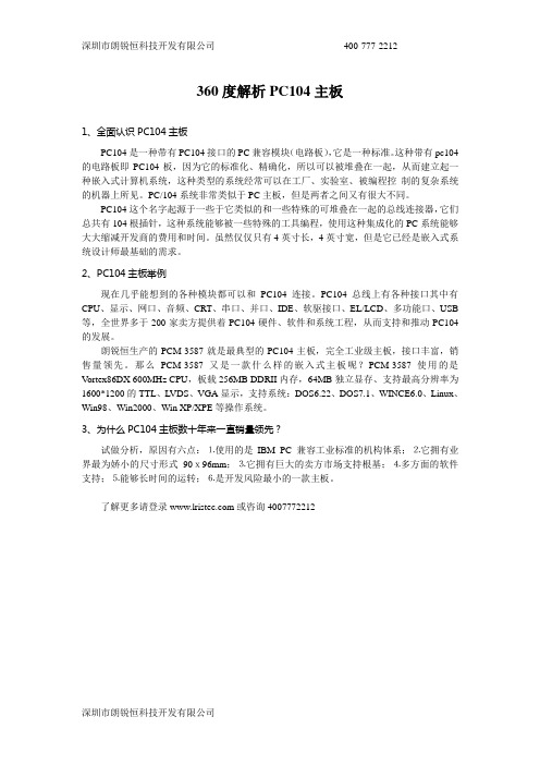
深圳市朗锐恒科技开发有限公司400-777-2212360度解析PC104主板1、全面认识PC104主板PC104是一种带有PC104接口的PC兼容模块(电路板),它是一种标准。
这种带有pc104的电路板即PC104板,因为它的标准化、精确化,所以可以被堆叠在一起,从而建立起一种嵌入式计算机系统,这种类型的系统经常可以在工厂、实验室、被编程控制的复杂系统的机器上所见。
PC/104系统非常类似于PC主板,但是两者之间又有很大不同。
PC104这个名字起源于一些于它类似的和一些特殊的可堆叠在一起的总线连接器,它们总共有104根插针,这种系统能够被一些特殊的工具编程,使用这种集成化的PC系统能够大大缩减开发商的费用和时间。
虽然仅仅只有4英寸长,4英寸宽,但是它已经是嵌入式系统设计师最基础的需求。
2、PC104主板举例现在几乎能想到的各种模块都可以和PC104连接。
PC104总线上有各种接口其中有CPU、显示、网口、音频、CRT、串口、并口、IDE、软驱接口、EL/LCD、多功能口、USB 等,全世界多于200家卖方提供着PC104硬件、软件和系统工程,从而支持和推动PC104的发展。
朗锐恒生产的PCM-3587就是最典型的PC104主板,完全工业级主板,接口丰富,销售量领先。
那么PCM-3587又是一款什么样的嵌入式主板呢?PCM-3587使用的是V ortex86DX 600MHz CPU,板载256MB DDRII内存,64MB独立显存、支持最高分辨率为1600*1200的TTL、LVDS、VGA显示,支持系统:DOS6.22、DOS7.1、WINCE6.0、Linux、Win98、Win2000、Win XP/XPE等操作系统。
3、为什么PC104主板数十年来一直销量领先?试做分析,原因有六点:⒈使用的是IBM PC 兼容工业标准的机构体系;⒉它拥有业界最为娇小的尺寸形式90x96mm;⒊它拥有巨大的卖方市场支持根基;⒋多方面的软件支持;⒌能够长时间的运转;⒍是开发风险最小的一款主板。
- 1、下载文档前请自行甄别文档内容的完整性,平台不提供额外的编辑、内容补充、找答案等附加服务。
- 2、"仅部分预览"的文档,不可在线预览部分如存在完整性等问题,可反馈申请退款(可完整预览的文档不适用该条件!)。
- 3、如文档侵犯您的权益,请联系客服反馈,我们会尽快为您处理(人工客服工作时间:9:00-18:30)。
PC/104-Plus SpecificationVersion 1.0February 1997Please NoteThis specification is subject to change without notice. While every effort has been made to ensure the accuracy of the material contained within this document, the PC/104 Consortium shall under no circumstances be liable for incidental or consequential damages or related expenses resulting from the use of this specification. If errors are found, please notify thePC/104 Consortium.PC/104 and PC/104-Plus are trademarks of the PC/104 Consortium. All other marks are the property of their respective companies.Copyright 1992-97, PC/104 ConsortiumREVISION HISTORYDraft 0.7, November 20, 96 - Preliminary Drafta.Formatted to meet the requirements of the PC/104 Consortium.b.Modify the component restrictions across and to each side of the PC/104 connectors (threesides, .400“ from each edge, 4.35" top clearance, .100" bottom clearance).Draft 0.8, December 16, 1996 - Cleanup for releasea.Correct general typosb.Correct word reference errorc.Add QuickSwitch part number and clarify Mux requirementsd.Change PCI ONLY to PCI-Only and add notee.Correct figure 4 and Figure 5 errorsf.Correct typo in Table 3Draft 0.9,January 10, 1997 - Cleanup for releasea.Cleanup minor grammatical errorsVersion 1.0, February 1997 - Initial Releasea.Grammatical changes and cleanup per review recommendations.b.Change Footnote 1 on Page 2 to show future support for the M66EN (66MHz Enable) signal.c.Add signals PRSNT[1:2]* and CLKRUN* to Figure 1 to encompass all unused PCI signals.d.Moved the Mechanical section after the Electrical section.e.Clarified the KEY pin usage for universal modules and defined them as ground connections.f.Clarified pin 1 for the PC/104-Plus connectors on Figure 4.g.Added an example manufacturer and part No. for the PCI connector (Figure 5) and Shroud(Figure 6).h.Modified Figure 2, Table 1, and some text under Section 2.2 to add routing recommendationsfor the PCI interrupt lines INTA - INTD.TABLE OF CONTENTS1. INTRODUCTION (1)1.1S UMMARY OF K EY D IFFERENCES F ROM PC/104S PECIFICATION: (1)1.2S UMMARY OF K EY D IFFERENCES (120-PIN PCI AND PCI L OCAL B US S PECIFICATION) (1)1.3R EFERENCES (1)2. PCI SIGNAL DEFINITION (2)2.1PCI B US S IGNAL D ESCRIPTION (3)2.1.1 System (3)2.1.2 Address and Data (3)2.1.3 Interface Control Pins (3)2.1.4 Arbitration (Bus Masters Only) (3)2.1.5 Error Reporting (3)2.1.6 Interrupts (3)2.2S IGNAL G ROUPING (4)3. ELECTRICAL SPECIFICATION (5)3.1PC/104B US (5)3.2PCI B US (5)3.2.1 Signal Definitions (5)3.2.2 Signal Assignments (5)3.2.3 Power And Ground Pins (5)3.2.4 Key Locations (5)3.2.5 AC/DC Signal Specifications (6)3.3M ODULE P OWER R EQUIREMENTS (7)4. LEVELS OF CONFORMANCE (7)4.1PC/104-P LUS"C OMPLIANT" (7)4.2PC/104-P LUS "B US-COMPATIBLE" (7)4.3PC/104-P LUS "PCI-O NLY" (7)5. MECHANICAL SPECIFICATION (8)5.1M ODULE D IMENSIONS (8)5.2C ONNECTOR A ND S HROUD (8)6. TYPICAL MODULE STACK (9)APPENDICESA. MECHANICAL DIMENSIONS ............................................................................................ A-1B. BUS SIGNAL ASSIGNMENTS ............................................................................................. B-1TABLE OF FIGURESF IGURE 1:PCI P IN L IST (2)F IGURE 2:S IGNAL S ELECT (4)F IGURE 3:T YPICAL M ODULE S TACK (9)F IGURE 4:M ODULE D IMENSIONS (2)F IGURE 5:PCI C ONNECTOR (3)F IGURE 6:PCI S HROUD (3)TABLE OF TABLESF IGURE 1:PCI P IN L IST (2)F IGURE 2:S IGNAL S ELECT (4)F IGURE 3:T YPICAL M ODULE S TACK (9)F IGURE 4:M ODULE D IMENSIONS (2)F IGURE 5:PCI C ONNECTOR (3)F IGURE 6:PCI S HROUD (3)PC/104-Plus SPECIFICATIONVersion 1.0 February 19971.INTRODUCTIONWhile the PC/AT architecture is becoming increasingly popular in embedded applications, there is an increasing need for a higher performance Bus throughput. This is especially true when it comes to graphics devices as well as other high speed I/O devices such as networks.This document supplies the mechanical and electrical specifications for the 揚C/104-Plus” and incorporates all of the PC/104 features, with the added advantage of the high speed PCI bus. The physical size, mounting configuration and electrical interconnect portion of the PC/104 specification shall remain unchanged.1.1Summary of Key Differences From PC/104 Specification:⏹ A third connector opposite the PC/104 connectors supports the PCI bus.⏹Changes to the component height requirements increase the flexibility of the module.⏹Control logic added to handle the requirements for the high speed bus.1.2Summary of Key Differences (120-pin PCI and PCI Local Bus Specification)⏹The PCI bus connector is a 4x30 (120-pin) 2mm pitch stackthrough connector as opposedto the 124-pin edge connector on standard 32-bit PCI Local Bus.⏹The 120-pin PCI does not support 64-bit Extensions, JTAG, PRSNT, or CLKRUN signals.1.3ReferencesThis document covers the addition of the PCI functions. The following documents should be used as reference for a detailed understanding of the overall system requirements:⏹PC/104 Specification Version 2.3⏹PCI Local Bus Specification Revision 2.1Contact the PCI Special Interest Group office for the latest revision of the PCI specification:PCI Special Interest GroupP.O. Box 14070Portland, OR 97214800.433.5177 (U.S.) 503.797.4207 (International)If errors are found in this document, please send a written copy of the suggested corrections to:PC/104 Consortium849B Independence AveMountain View, CA 94043Tel 415.903.8304Fax 415.967.09952. PCI SIGNAL DEFINITIONFigure 1 shows the pins in functional groups, with the required pins on the left and the optional pins on the right side. The shaded pins on the right are unsupported features, but are included to show the entire PCI bus as defined in the PCI Revision 2.1 Specification. This version of the PCI bus is intended as a 32-bit bus running at 33MHz and therefore, 64-bit extension and 66MHz 1 are not supported at this time. Also not supported are the boundary scan features (JTAG), Present (PRSNR[1:2]*), and Clock running (CLKRUN*). The direction indication on the pins assumes a combination master/target device.Figure 1: PCI Pin List1The PCI bus has been simulated at 33MHz. For the purpose of this specification, 66MHz is not supported. Tosupport future enhancements, the M66EN signal should be grounded on any module that cannot support 66MHz and left open for modules that can support a 66MHz clocks.Address & DataReporting2.1PCI Bus Signal Description2.1.1SystemCLK Clock provides timing for all transactions on the PCI bus.RST* Reset is used to bring PCI-specific registers to a known state.2.1.2Address and DataAD[31:00] Address and Data are multiplexed. A bus transaction consists of an addresscycle followed by one or more data cycles.C/BE[3:0]* Bus Command/Byte Enables are multiplexed. During the address cycle, thecommand is defined. During the Data cycle, they define the byte enables.PAR Parity is even on AD[31:00] and C/BE[3:0]* and is required.2.1.3Interface Control PinsFRAME* Frame is driven by the current master to indicate the start of a transaction andwill remain active until the final data cycle.IRDY* Initiator Ready indicates the master's ability to complete the current datacycle of the transaction.TRDY* Target Ready indicates the selected devices ability to complete the currentdata cycle of the transaction. Both IRDY* and TRDY* must be asserted toterminate a data cycle.STOP* Stop indicates the current selected device is requesting the master to stop thecurrent transaction.LOCK* Lock indicates an operation that may require multiple transactions tocomplete.IDSEL Initialization Device Select is used as a chip-select during configuration.DEVSEL* Device Select is driven by the target device when its address is decoded.2.1.4Arbitration (Bus Masters Only)REQ* Request indicates to the arbitrator that this device desires use of the bus.GNT* Grant indicates to the requesting device that access has been granted.2.1.5Error ReportingPERR* Parity Error is for reporting data parity errors.SERR* System Error is for reporting address parity errors.2.1.6InterruptsINTA* Interrupt A is used to request an Interrupt.INTB* Interrupt B is used to request interrupts only for multi-function devices.INTC* Interrupts C is used to request interrupts only for multi-function devices.INTD* Interrupts D is used to request interrupts only for multi-function devices.2.2Signal GroupingA means of selecting the appropriate signals must be established that will easily allow for the installation and configuration of add-in PC/104-Plus modules. Figure 2 shows such a method:Figure 2: Signal SelectThe multiplexer chips are Dual 4:1 Mux/Demux chips (QuickSwitch® QS3253 or equivalent). They provide a 5Ω switch that connects the input and output together. The nature of the switches, provide a bi-directional path with no signal propagation delay other than the RC delay of the on resistance of the switch and the load capacitance. This is typically 250ps at 50pF Load.Other methods of configuring the modules are possible, but the rotary switch is the most convenient, cleanest and provides for the least possible error in configuration.The clocks are tuned on the Host Board such that the length of CLK3 trace is ≈0.662" less than CLK2, CLK2 trace is ≈0.662" less than CLK1, and CLK1 trace is ≈0.662" less than CLK0. Therefore, the first module on the stack must select CLK0 (the longest trace), the second CLK1, etc. This provides basically no clock skew between modules. Table 1 shows the appropriate switch setting and signals used for each module in the stack. It is recommended that additional Mux chips be added to route Interrupts if required. Use one Mux for 1 to 2 interrupts or two Mux's for 3 to 4 interrupts.Table 1: Rotary Switch Settings3.ELECTRICAL SPECIFICATION3.1PC/104 BusThe electrical specifications for the PC/104 bus for bus drive current, bus termination,pullup/pulldown resistors, etc. are unchanged and are defined in the PC/104 Specification. The signal assignments for the J1/P1 and J2/P2 connector are given in Appendix B, Table 4: PC/104 Bus (Reference Only).3.2PCI BusThe PCI Bus mechanical interface is a stackable 30x4 header. This interface carries all of the required PCI signals per PCI Local Bus Specification Version. 2.1.3.2.1Signal DefinitionsFor full details on the electrical requirements for the PCI bus, reference the PCI Local Bus Specification Version. 2.1.3.2.2Signal AssignmentsSignals are assigned in the same relative order as in the PCI Local Bus Specification, but transformed to the corresponding header connector pins. Because of the stackthrough nature of the bus, slot-specific signals are duplicated for each plug-in module. The system has been designed to accommodate 4 PC/104-Plus modules, so multiple sets of the signals have been duplicated to accommodate one signal for each module. These four signal groups include: IDSEL[3:0] - CLK[3:0] - REQ*[2:0] - GNT*[2:0]. Signal assignments for the J3/P3connector are given in Appendix B, Table 3: PC/104-Plus Bus Signal Assignments.3.2.3Power And Ground PinsThe total number of power and ground signals remains the same, but the +3.3 V pins have been reduced by two and the ground pins have been increased by two. The change was the result of signal grouping on the bus and has no effect on performance or integrity.3.2.4Key LocationsThe KEY pins are to guarantee proper module installation. Pin-A1 will be removed and the female side plugged for 5.0V I/O signals and Pin-D30 will be modified in the same manner for 3.3V I/O. Universal boards which can support either signal levels will have both key pins implemented. Universal boards must therefore be located at the top of the stack. See Appendix B, Table 3: PC/104-Plus Bus Signal Assignments.3.2.5AC/DC Signal SpecificationsAll bus timing and signal levels are identical to the PCI Local Bus Specification Revision2.1.3.3Module Power RequirementsTable 2 specifies the voltage and maximum power requirements for each PC/104-Plus module. It should be noted that although the maximum requirements as specified are the same as the standard PC/104 specification, care should be used in designing PC/104-Plus modules to guarantee the least possible power consumption. A worst case module as specified could use almost 39 Watts of power, which would basically be unacceptable in most systems.Table 2: Module Power Requirementsprovide a bus and decoupling. If 3.3 volts is required for a module using the 5V signaling method,provisions should be made to provide its own 3.3 volts by means of an onboard regulator or someother input source. Host Boards implementing 3.3V signaling are required to supply 3.3 volts to themodules.4.LEVELS OF CONFORMANCEThis section provides terminology intended to assist manufacturers and users of PC/104-Plus bus-compatible products in defining and specifying conformance with the PC/104-Plus Specification.4.1PC/104-Plus "Compliant"This refers to "PC/104-Plus form-factor" devices that conform to all non-optional aspects of the PC/104-Plus Specification, including both mechanical and electrical specifications.4.2PC/104-Plus "Bus-compatible"This refers to devices which are not "PC/104-Plus form-factor" (i.e., do not comply with the module dimensions of the PC/104-Plus Specification), but provide male or female PC/104-Plus bus connectors that meets both the mechanical and electrical specifications provided for the PC/104-Plus bus connectors.4.3PC/104-Plus "PCI-Only"2Because the PC/104-Plus standard encompasses two different buses (i.e. PC/104 104-pin "ISA" bus and 120-pin "PCI" bus), it is possible for PC/104-Plus compliant or compatible modules to implement PCI only. Such modules shall have the added designation "PCI-Only" in addition to 2 This precludes stacking standard PC/104 Modules.the designation specified in either 4.1 and 4.2. Example: PC/104-Plus "Compliant", PCI-Only or PC/104-Plus "Bus-compatible", PCI-Only.5.MECHANICAL SPECIFICATION5.1Module DimensionsThe mechanical dimensions for this module are identical to PC/104 specification with the exception of the added connector (J3), some modifications to the I/O connector area, and changes to the component height restrictions. The component height on the top side has been reduced from 0.435" to 0.345" and the bottom has been increased from 0.100" to 0.190". The component restrictions across and to each side of the PC/104 connectors (three sides, 0.400" from each edge) remains the same as the PC/104 specification. The mechanical dimensions and restrictions are given in Appendix A, Figure 4: Module Dimensions.5.2Connector And ShroudThe PC/104-Plus connector for the PCI bus is a 4x30 (120-pin) 2mm pitch connector. The Shroud should be installed on the bottom of the PC board when a stackthrough connector is used. The mechanical dimensions and restrictions are given in Appendix A, Figure 5: PCI Connector.6. TYPICAL MODULE STACKFigure 3 shows a typical module stack with 2 PC/104-Plus modules, 1 PC/104 16-Bit module, and 1 PC/104 8-Bit module. The maximum configuration for the PCI bus of PC/104-Plus modules is 4 plus the Host Board. If standard PC/104 modules are used in the stack, they must be the top module(s) because they will normally not include the PCI bus.Stackthrough 8-bit moduleStackthrough 16-bit moduleStackthroughPC/104-Plus moduleNon-stackthrough PC/104-Plus moduleAPPENDIX A MECHANICAL DIMENSIONSPC/104-Plus Figure 4: Module DimensionsPC/104-PlusFigure 5: PCI Connector A shows the pin dimensions for the Stackthrough connector.(Samtec ESQT-130-02-G-Q-368 or equivalent)B shows the pin dimensions for the Soldertail connector.(Samtec ESQT-130-03-M-Q-368 or equivalent)Figure 6: PCI Shroud (Samtec TS-30-Q or equivalent)APPENDIX BBUS SIGNAL ASSIGNMENTSTable 3: PC/104-Plus Bus Signal Assignments2. The KEY pins are to guarantee proper module installation. Pin-A1 will be removed and thefemale side plugged for 5.0V I/O signals and Pin-D30 will be modified in the same manner for3.3V I/O. It is recommended that both KEY pins (A1 and D30) be electrically connected toGND for shielding.Table 4: PC/104 Bus (Reference Only)。