2SA1618GR中文资料
2SA2151中文资料

2SA2151DescriptionBy adapting the Sanken unique wafer-thinner technique, thesePNP power transistors achieve power-up by decreasing thermalresistance, and provide higher voltage avalanche breakdownrating. The high power-handling capacity of the TO-3P packageallows a smaller footprint on the circuit board design. Thisseries of transistors is very well suited to not only multichannelapplications for A V (audio-visual) amplifiers and receivers,but also parallel connection applications for PA (professionalaudio system) amplifiers.Applications include the following:▪Single transistors for audio amplifiers▪Home audio amplifiers▪Professional audio amplifiers▪Automobile audio amplifiers▪ Audio market▪Single transistors for general purposeFeatures and Benefits▪Small package (TO-3P)▪High power handling capacity, 160 W▪Improved sound output by reduced on-chip impedance▪For professional audio (PA) applications, V CEO = –200 Vversions available▪Complementary to 2SC6011▪Recommended output driver: 2SA1668Audio Amplification TransistorPackage: 3 Lead TO-3PAudio Amplification Transistor2SA2151ABSOLUTE MAXIMUM RATINGS at T A = 25°CCharacteristicSymbol Rating Unit Collector-Base Voltage V CBO –200V Collector-Emitter Voltage V CEO –200V Emitter-Base Voltage V EBO –6V Collector Current I C –15A Base CurrentI B –4A Collector Power Dissipation P C 160W Junction Temperature T J 150°C Storage TemperatureT stg–55 to150°CSELECTION GUIDEPart NumberTypeh FE RatingPacking2SA2151*PNPRange O: 50 to 100Bulk, 100 pieces Range P: 70 tp 140Range Y: 90 to 180*Specify h FE range when ordering. If no h FE range is specified, order will be fulfilled with either or both range O and range Y , depending upon availability.ELECTRICAL CHARACTERISTICS at T A = 25°CCharacteristicSymbol Test ConditionsMin.Typ.Max.Unit Collector-Cutoff Current I CBO V CB = –200 V –––10μA Emitter Cutoff Current I EBO V EB = –6 V –––10μA Collector-Emitter Voltage V (BR)CEOI C = –50 mA –200––V DC Current Transfer Ratio*h FE V CE = –4 V, I C = –3 A 50–180–Collector-Emitter Saturation Voltage V CE(sat)I C = –5 A, I B = –0.5 A –––0.5V Cutoff Frequency f T V CE = –12 V, I E = 0.5 A–20–MHz Output CapacitanceC OBV CB = –10 V, I E = 0 A, f = 1 MHz–450–pF*h FE rating: 50 to 100 (O brand on package), 70 to 140 (P), 90 to 180 (Y).Audio Amplification Transistor2SA2151Performance Characteristics–I C (A )I C vs.V CEI C vs.V BE–V CE =4V Continuous–I C (A )05h FE vs. I C–V CE =4V Continuous–I C (A)h F Et (ms)Audio Amplification Transistor2SA2151–I C (A )–V CE (V)Safe Operating AreaT A = 25°C, single pulse, no heatsink, natural cooling 102030f T vs. I E –V CE = 12 V Continuousf T (M H z )I E (A)P C vs. T AT A (°C)P (W )Performance Characteristics, continuedAudio Amplification Transistor2SA2151Terminal core material: CuTerminal treatment: Ni plating and solder dip Heat sink core material: Cu Heat sink treatment: Ni plating Leadform number: 100Dimensions in millimetersBranding codes (exact appearance at manufacturer discretion):1st line, type: A21512nd line, lot: YM H Where: Y is the last digit of the year of manufacture M is the month (1 to 9, O, N, D )H is the h FE rating (O, P , or Y ; for values see footnote, Electrical Characteristics table)PACKAGE OUTLINE DRAWING, TO-3PLeadframe plating Pb-free. Device composition includes high-temperature solder (Pb >85%), which is exempted from the RoHS directive.Audio Amplification Transistor 2SA2151Because reliability can be affected adversely by improper storage environments and handling methods, please observe the following cautions.Cautions for Storage• Ensure that storage conditions comply with the standard temperature (5°C to 35°C) and the standard relative humidity(around 40 to 75%); avoid storage locations that experienceextreme changes in temperature or humidity.• Avoid locations where dust or harmful gases are present and avoid direct sunlight.• Reinspect for rust on leads and solderability of products that have been stored for a long time.Cautions for Testing and HandlingWhen tests are carried out during inspection testing and otherstandard test periods, protect the products from power surgesfrom the testing device, shorts between adjacent products, and shorts to the heatsink.Remarks About Using Silicone Grease with a Heatsink• When silicone grease is used in mounting this product on a heatsink, it shall be applied evenly and thinly. If more siliconegrease than required is applied, it may produce stress.• Coat the back surface of the product and both surfaces of the insulating plate to improve heat transfer between the product and the heatsink.• Volatile-type silicone greases may permeate the product and produce cracks after long periods of time, resulting in reducedheat radiation effect, and possibly shortening the lifetime of theproduct.• Our recommended silicone greases for heat radiation purposes, which will not cause any adverse effect on the product life, areindicated below:Type SuppliersG746Shin-Etsu Chemical Co., Ltd.YG6260GE Toshiba Silicone Co., Ltd.SC102Dow Corning Toray Silicone Co., Ltd.Heatsink Mounting Method• Torque When Tightening Mounting Screws. Thermal resistance increases when tightening torque is low, and radiation effects are decreased. When the torque is too high, the screw can strip, the heatsink can be deformed, and distortion can arise in the product frame.To avoid these problems, observe the recommended tightening torques for this product package type, TO-3P (MT-100): 0.686 to 0.882 N•m (7 to 9 kgf•cm).• Diameter of Heatsink Hole: < 4 mm. The defl ection of the press mold when making the hole may cause the case material to crack at the joint with the heatsink. Please pay special attention for this effect.Soldering• When soldering the products, please be sure to minimize the working time, within the following limits:260±5°C 10 s350±5°C 3 s• Soldering iron should be at a distance of at least 1.5 mm from the body of the productsElectrostatic Discharge• When handling the products, operator must be grounded.Grounded wrist straps worn should have at least 1 MΩ ofresistance to ground to prevent shock hazard.• Workbenches where the products are handled should begrounded and be provided with conductive table and floor mats.• When using measuring equipment such as a curve tracer, the equipment should be grounded.• When soldering the products, the head of soldering irons or the solder bath must be grounded in other to prevent leak voltagesgenerated by them from being applied to the products.• The products should always be stored and transported in our shipping containers or conductive containers, or be wrapped inaluminum foil.Audio Amplification Transistor 2SA2151The products described herein are manufactured in Ja p an by Sanken Electric Co., Ltd. for sale by Allegro MicroSystems, Inc.Sanken and Allegro reserve the right to make, from time to time, such de p ar t ures from the detail spec i f i c a t ions as may be re q uired to per m it im-p rove m ents in the per f or m ance, reliability, or manufacturability of its prod u cts. Therefore, the user is cau t ioned to verify that the in f or m a t ion in this publication is current before placing any order.When using the products described herein, the ap p li c a b il i t y and suit a bil i t y of such products for the intended purpose shall be reviewed at the users responsibility.Although Sanken undertakes to enhance the quality and reliability of its prod u cts, the occurrence of failure and defect of semi c on d uc t or products at a certain rate is in e v i t a b le.Users of Sanken products are requested to take, at their own risk, preventative measures including safety design of the equipment or systems against any possible injury, death, fires or damages to society due to device failure or malfunction.Sanken products listed in this publication are designed and intended for use as components in general-purpose electronic equip m ent or apparatus (home ap p li a nc e s, office equipment, tele c om m u n i c a t ion equipment, measuring equipment, etc.). Their use in any application requiring radiation hardness assurance (e.g., aero s pace equipment) is not supported.When considering the use of Sanken products in ap p li c a t ions where higher reliability is re q uired (transportation equipment and its control systems or equip m ent, fire- or burglar-alarm systems, various safety devices, etc.), contact a company sales representative to discuss and obtain written confirmation of your spec i f i c a t ions.The use of Sanken products without the written consent of Sanken in applications where ex t reme l y high reliability is required (aerospace equip-ment, nuclear power-control stations, life-support systems, etc.) is strictly prohibited.The information in c lud e d herein is believed to be accurate and reliable. Ap p li c a t ion and operation examples described in this pub l i c a t ion are given for reference only and Sanken and Allegro assume no re s pon s i b il i t y for any in f ringe m ent of in d us t ri a l property rights, intellectual property rights, or any other rights of Sanken or Allegro or any third party that may result from its use.Anti radioactive ray design is not considered for the products listed herein.Copyright © 2006 Allegro MicroSystems, Inc.This datasheet is based on Sanken datasheet SSE-23012。
2SA966资料

TOSHIBA Transistor Silicon PNP Epitaxial Type (PCT Process)2SA966Audio Power Amplifier Applications• Complementary to 2SC2236 and 3-W output applications.Absolute Maximum Ratings (Ta = 25°C)Characteristics Symbol Rating UnitCollector-base voltage V CBO −30 V Collector-emitter voltage V CEO −30 V Emitter-base voltage V EBO −5 V Collector current I C−1.5 AEmitter currentI E 1.5 A Collector power dissipation P C 900 mW Junction temperature T j 150 °C Storage temperature rangeT stg−55 to 150°CNote: Using continuously under heavy loads (e.g. the application of high temperature/current/voltage and the significant change in temperature, etc.) may cause this product to decrease in thereliability significantly even if the operating conditions (i.e. operating temperature/current/voltage, etc.) are within the absolute maximum ratings.Please design the appropriate reliability upon reviewing the Toshiba Semiconductor Reliability Handbook (“HandlingPrecautions”/Derating Concept and Methods) and individual reliability data (i.e. reliability test report and estimated failure rate, etc).Unit: mmJEDEC TO-92MOD JEITA ―TOSHIBA 2-5J1A Weight: 0.36 g (typ.)Electrical Characteristics (Ta = 25°C)Characteristics Symbol TestCondition MinTyp.Max UnitCollector cut-off current I CBO V CB = −30 V, I E = 0 ――−100nAEmitter cut-off current I EBO V EB = −5 V, I C = 0 ――−100nA Collector-emitter breakdown voltage V (BR) CEO I C = −10 mA, I B = 0 −30 ―― V Emitter-base breakdown voltage V (BR) EBO I E = −1 mA, I C = 0 −5 ―― VDC current gain h FE(Note)V CE = −2 V, I C = −500 mA 100 ― 320Collector-emitter saturation voltage V CE (sat)I C = −1.5 A, I B = −0.03 A ――−2.0V Base-emitter voltage V BE V CE = −2 V, I C = −500 mA ――−1.0V Transition frequency f T V CE = −2 V, I C = −500 mA ― 120 ― MHz Collector output capacitance C ob V CB = −10 V, I E = 0, f = 1 MHz ― 40 ― pF Note: h FE classification O: 100 to 200, Y: 160 to 320Markinglead (Pb)-free package orlead (Pb)-free finish.indicatorCollector current I C (mA)h FE – ICD C c u r re n t g a i n h F ECollector current I C (mA)V CE (sat) – I CC o l l e c t o r -e m i t t e r s a t u r a t i on v o l t a g eV C E (s a t ) (V )Base-emitter voltage V BE (V)I C – V BEC oll e c t o rc u r r e n t I C (m A )Ambient temperature Ta (°C)P C – TaC o l l e c t o r p owe r d i s s ip a t io n P C (W )Collector-emitter voltage V CE (V)Safe Operating AreaC o l l e c t o r c u r r e n t I C (A )1.00 0 20 40 60 80 100 120 140 160 1800.20.40.60.8−−−−−−−−−−−−−−−−−−Collector-emitter voltage V CE (V)I C – V CEC o l l e c t o r c u r r e n t I C (m A )−−−−−−−−−−−−−−−−−RESTRICTIONS ON PRODUCT USE20070701-EN •The information contained herein is subject to change without notice.•TOSHIBA is continually working to improve the quality and reliability of its products. Nevertheless, semiconductor devices in general can malfunction or fail due to their inherent electrical sensitivity and vulnerability to physical stress. It is the responsibility of the buyer, when utilizing TOSHIBA products, to comply with the standards of safety in making a safe design for the entire system, and to avoid situations in which a malfunction or failure of such TOSHIBA products could cause loss of human life, bodily injury or damage to property.In developing your designs, please ensure that TOSHIBA products are used within specified operating ranges as set forth in the most recent TOSHIBA products specifications. Also, please keep in mind the precautions and conditions set forth in the “Handling Guide for Semiconductor Devices,” or “TOSHIBA Semiconductor Reliability Handbook” etc.• The TOSHIBA products listed in this document are intended for usage in general electronics applications (computer, personal equipment, office equipment, measuring equipment, industrial robotics, domestic appliances, etc.).These TOSHIBA products are neither intended nor warranted for usage in equipment that requires extraordinarily high quality and/or reliability or a malfunction or failure of which may cause loss of human life or bodily injury (“Unintended Usage”). Unintended Usage include atomic energy control instruments, airplane or spaceship instruments, transportation instruments, traffic signal instruments, combustion control instruments, medical instruments, all types of safety devices, etc.. Unintended Usage of TOSHIBA products listed in his document shall be made at the customer’s own risk.•The products described in this document shall not be used or embedded to any downstream products of which manufacture, use and/or sale are prohibited under any applicable laws and regulations.• The information contained herein is presented only as a guide for the applications of our products. No responsibility is assumed by TOSHIBA for any infringements of patents or other rights of the third parties which may result from its use. No license is granted by implication or otherwise under any patents or other rights of TOSHIBA or the third parties.• Please contact your sales representative for product-by-product details in this document regarding RoHS compatibility. Please use these products in this document in compliance with all applicable laws and regulations that regulate the inclusion or use of controlled substances. Toshiba assumes no liability for damage or losses occurring as a result of noncompliance with applicable laws and regulations.。
2SD1899中文资料(Weitron Technology)中文数据手册「EasyDatasheet - 矽搜」

芯片中文手册,看全文,戳
2SD1899
典型特征
3/4
13-Oct-08
芯片中文手册,看全文,戳
2SD1899
TO-252外形尺寸
单位:mm
E A 4 G H J 1 2 3
B
TO-252
Dim A B C D E G H J K L M
M D C L K
Min 6.40 9.00 0.50 2.20 0.45 1.00 5.40 0.30 0.70 0.90
120 30
10 10
60 100 50
400
DC电 流 增 益
hFE(2) hFE(3)
0.25 1.2 V V MHz pF
集电极 - 发射极饱和电压 基地发射极饱和电压 转换频率 集电极输出电容
开启时间
V CE(sat) V BE(sat) fT C ob ton t stg tf
切换时间
贮存时间 下降时间
芯片中文手册,看全文,戳
2SD1899
NPN塑料封装晶体管
P b 铅( Pb) - 免费
1.BASE 2.COLLECTOR 3.EMITTER 1 2 3
( T最大额定值
参数 集电极基极电压 集电极 - 发射极电压 发射基电压 集电极电流 - 连续 集电极耗散功率 结温 储存温度
A= 25℃除非另有说明)
D-PAK(TO-252)
Units V V V A W
℃ ℃
符
Value V CBO V CEO V EBO IC PC TJ Tstg 60 60 7 3 1 150 -55-150
电气特性(除非另有说明 ,环境温度 Tamb = 25℃)
参数 符
2SA2222中文资料
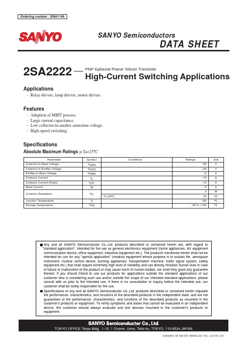
Specifications
Absolute Maximum Ratings at Ta=25°C
Parameter Collector-to-Base Voltage Collector-to-Emitter Voltage Emitter-to-Base Voltage Collector Current Collector Current (Pulse) Base Current
Applications
• Relay drivers, lamp drivers, motor drivers.
Features
• Adoption of MBIT process. • Large current capacitance. • Low collector-to-emitter saturation voltage. • High-speed switching.
--15mA --10mA
--80mA
--5mA
IB=0mA
--0.5
--1.0
--1.5
--2.0
Collector-to-Emitter Voltage, VCE -- V IT13442
No. A1148-2/4
元器件交易网
2SA2222
Collector Current, IC -- A
TOKYO OFFICE Tokyo Bldg., 1-10, 1 Chome, Ueno, Taito-ku, TOKYO, 110-8534 JAPAN
32608FA TI IM TC-00001283 No. A1148-1/4
元器件交易网
2SA2222
Electrical Characteristics at Ta=25°C
2SA1774贴片三极管 SOT-523三极管封装2SA1774参数

Q
120-270 FQ
R
180-390 FR
S
270-560 FS
(2).Pulse Test :Pulse Width ≤300us,D.C ≤ 2%
B,Jan,2013
【 南京南山半导体有限公司 — 长电贴片三极管选型资料】
Typical Characteristics
600 500 400
(mA)
-80
-350uA
COLLECTOR CURRENT
IC
-60
300
Ta=25 ℃
200
-40
-150uA -100uA
-20
IB=-50uA
-0 -0 -2 -4 -6 -8 -10 100 -0.3
-1
-3
-10
-30
-100
-200
COLLECTOR-EMITTER VOLTAGE
【 南京南山半导体有限公司 — 长电贴片三极管选型资料】
JIANGSU CHANGJIANG ELECTRONICS TECHNOLOGY CO., LTD
SOT-523 Plastic-Encapsulate Transistors
2SA1774
TRANSISTOR (PNP)
COLLECTOR CURRENT
IC
(mA)
-100
IC
——
VBE
VCE=-6V
30
Cob/ Cib
——
VCB/ VEB
f=1MHz IE=0/IC=0 Ta=25℃
(mA)
-30
(pF)
IC
-10
2SA1615中文资料

Document No. D16119EJ1V0DS00 (1st edition)Date Published April 2002 N CP(K)Printed in JapanSILICON POWER TRANSISTORS2SA1615, 1615-ZPNP SILICON EPITAXIAL TRANSISTORFOR HIGH-SPEED SWITCHINGDATA SHEETThe information in this document is subject to change without notice. Before using this document, please confirm that this is the latest version.Not all devices/types available in every country. Please check with local NEC representative for availability and additional information.©2002The 2SA1615 and 1615-Z are available for the large current control in small dimension due to the low saturation and are ideal for high-efficiency DC/DC converters due to the fast switching speed.FEATURES•Large current capacity:I C(DC): −10 A, I C(pulse): −15 A•High h FE and low collector saturation voltage:h FE = 200 MIN. (@V CE = −2.0 V, I C = −0.5 A)V CE(sat) ≤ −0.25 V (@I C = −4.0 A, I B = −0.05 A)QUALITY GRADES•StandardPlease refer to “Quality Grades on NEC Semiconductor Devices” (Document No. C11531E) published by NEC Corporation to know the specification of quality grade on the devices and its recommended applications.ABSOLUTE MAXIMUM RATINGS (Ta = 25°C)ParameterSymbol Ratings Unit Collector to base voltage V CBO −30V Collector to emitter voltage V CEO −20V Emitter to base voltage V EBO −10V Collector current (DC)I C(DC)−10A Collector current (pulse)I C(pulse)*−15A Base current (DC)I B(DC)−0.5A Total power dissipation P T (T a = 25°C)** 1.0W Total power dissipation P T (T c = 25°C)15W Junction temperature T j 150°C Storage temperatureT stg−55 to +150°C*PW ≤ 10 ms, duty cycle ≤ 50%**Printing board mountedData Sheet D16119EJ1V0DS2ELECTRICAL CHARACTERISTICS (Ta = 25°C)ParameterSymbol ConditionsMIN.TYP.MAX.UnitCollector cutoff current I CBO V CB = −20 V, I E = 0−1.0µA Emitter cutoff current I EBO V EB = −8.0 V, I C = 0−1.0µADC current gain h FE1*V CE = −2.0 V, I C = −0.5 A 200600DC current gainh FE2*V CE = −2.0 V, I C = −4.0 A 160Collector saturation voltage V CE(sat)*I C = −4.0 A, I B = −0.05 A −0.2−0.25V Base saturation voltage V BE(sat)*I C = −4.0 A, I B = −0.05 A −0.9−1.2V Gain bandwidth product f T V CE = −5.0 V, I E = 1.5 A 180MHz Output capacity C ob V CB = −10 V, I E = 0, f = 1.0 MHz 220pF Turn-on time t on 80ns Storage time t stg 300ns Fall timet fI C = −5.0 A, I B1 = −I B2 = 0.125 A,R L = 2.0 Ω, V CC ≅ −10 V60ns*Pulse test PW ≤ 350 µs, duty cycle ≤ 2%h FE CLASSIFICATIONMarking L K h FE2200 to 400300 to 600PACKAGE DRAWING (UNIT: mm)2SA1615 2SA1615-ZElectrode Connection 1. Base 2. Collector 3. Emitter 4. Collector (fin)Data Sheet D16119EJ1V0DS3TYPICAL CHARACTERISTICS (Ta = 25 °C)T o t a l P o w e r D i s s i p a t i o n P T (W )Case Temperature T C (°C)Collector to Emitter Voltage V CE (V)Case Temperature T C (°C)I C D e r a t i n g d T (%)C o l l e c t o r C u r r e n t I C (A )Collector to Emitter Voltage V CE (V)Base to Emitter Voltage V BE (V)Collector Current I C (A)C o l l e c t o r C u r r e n t I C (A )D C C u r r e n t G a i n h F EC o l l e c t o r C u r r e n t I C (A )Single pulse–15–10–5Data Sheet D16119EJ1V0DS4Collector Current I C (A)C o l l e c t o r S a t u r a t i o n V o l t a g e V C E (s a t ) (V )B a s e S a t u r a t i o n V o l t a g e V B E (s a t ) (V )Collector Current I C (A)SWITCHING TIME (t on , t stg , t f ) TEST CIRCUIT%DVH FXUUHQW ZDYHIRUP&ROOHFWRU FXUUHQW ZDYHIRUP[MEMO]Data Sheet D16119EJ1V0DS5M8E 00. 4The information in this document is current as of July, 2001. The information is subject to change without notice. For actual design-in, refer to the latest publications of NEC's data sheets or data books, etc., for the most up-to-date specifications of NEC semiconductor products. Not all products and/or types are available in every country. Please check with an NEC sales representative for availability and additional information.No part of this document may be copied or reproduced in any form or by any means without prior written consent of NEC. NEC assumes no responsibility for any errors that may appear in this document.NEC does not assume any liability for infringement of patents, copyrights or other intellectual property rights of third parties by or arising from the use of NEC semiconductor products listed in this document or any other liability arising from the use of such products. No license, express, implied or otherwise, is granted under any patents, copyrights or other intellectual property rights of NEC or others.Descriptions of circuits, software and other related information in this document are provided for illustrative purposes in semiconductor product operation and application examples. The incorporation of these circuits, software and information in the design of customer's equipment shall be done under the full responsibility of customer. NEC assumes no responsibility for any losses incurred by customers or third parties arising from the use of these circuits, software and information.While NEC endeavours to enhance the quality, reliability and safety of NEC semiconductor products, customers agree and acknowledge that the possibility of defects thereof cannot be eliminated entirely. To minimize risks of damage to property or injury (including death) to persons arising from defects in NEC semiconductor products, customers must incorporate sufficient safety measures in their design, such as redundancy, fire-containment, and anti-failure features.NEC semiconductor products are classified into the following three quality grades:"Standard", "Special" and "Specific". The "Specific" quality grade applies only to semiconductor products developed based on a customer-designated "quality assurance program" for a specific application. The recommended applications of a semiconductor product depend on its quality grade, as indicated below. Customers must check the quality grade of each semiconductor product before using it in a particular application."Standard":Computers, office equipment, communications equipment, test and measurement equipment, audioand visual equipment, home electronic appliances, machine tools, personal electronic equipment and industrial robots"Special":Transportation equipment (automobiles, trains, ships, etc.), traffic control systems, anti-disastersystems, anti-crime systems, safety equipment and medical equipment (not specifically designed for life support)"Specific":Aircraft, aerospace equipment, submersible repeaters, nuclear reactor control systems, lifesupport systems and medical equipment for life support, etc.The quality grade of NEC semiconductor products is "Standard" unless otherwise expressly specified in NEC's data sheets or data books, etc. If customers wish to use NEC semiconductor products in applications not intended by NEC, they must contact an NEC sales representative in advance to determine NEC's willingness to support a given application.(Note)(1)"NEC" as used in this statement means NEC Corporation and also includes its majority-owned subsidiaries.(2)"NEC semiconductor products" means any semiconductor product developed or manufactured by or forNEC (as defined above).••••••。
2SJ162中文资料
3
2SJ160, 2SJ161, 2SJ162
Power vs. Temperature Derating 150 Channel Dissipation Pch (W) –20 Ta = 25°C –10 Drain Current ID (A) 100 ID max (Continuous) PW (–14.3 V, –5 –7 A) = 10 0 m Maximum Safe Operation Area
150
–0.2 –5
ห้องสมุดไป่ตู้
–10 –20 –50 –100 –200 –500 Drain to Source Voltage VDS (V)
Typical Output Characteristics –10 TC = 25°C –1.0 –0.8 Drain Current ID (A)
Typical Transfer Characteristics
2SJ160, 2SJ161, 2SJ162
Silicon P-Channel MOS FET
Application
Low frequency power amplifier Complementary pair with 2SK1056, 2SK1057 and 2SK1058
Features
• • • • • • • Good frequency characteristic High speed switching Wide area of safe operation Enhancement-mode Good complementary characteristics Equipped with gate protection diodes Suitable for audio power amplifier
2SK30ATMGR中文资料

TOSHIBA Field Effect Transistor Silicon N Channel Junction Type2SK30ATMLow Noise Pre-Amplifier, Tone Control Amplifier andDC-AC High Input Impedance Amplifier CircuitApplications•High breakdown voltage: V GDS = −50 V•High input impedance: I GSS = −1 nA (max) (V GS = −30 V)•Low noise: NF = 0.5dB (typ.)(V DS = 15 V, V GS = 0, R G = 100 kΩ, f = 120 Hz)Absolute Maximum Ratings (Ta = 25°C)Characteristics SymbolRatingUnitGate-drain voltage V GDS−50VGate current I G 10mADrain power dissipation P D 100mWJunction temperature T j125 °CStorage temperature range T stg−55~125 °CNote: Using continuously under heavy loads (e.g. the application ofhigh temperature/current/voltage and the significant change intemperature, etc.) may cause this product to decrease in thereliability significantly even if the operating conditions (i.e.operating temperature/current/voltage, etc.) are within theabsolute maximum ratings.Please design the appropriate reliability upon reviewing theToshiba Semiconductor Reliability Handbook (“Handling Precautions”/“Derating Concept and Methods”) andindividual reliability data (i.e. reliability test report and estimated failure rate, etc).Electrical Characteristics (Ta = 25°C)Characteristics Symbol TestCondition MinTyp.Max Unit Gate cut-off current I GSS V GS=−30 V, V DS= 0 ⎯⎯−1.0nA Gate-drain breakdown voltage V (BR) GDS V DS= 0, I G=−100 μA −50 ⎯⎯ VDrain current I DSS(Note)V DS= 10 V, V GS= 0 0.3 ⎯ 6.5 mAGate-source cut-off voltage V GS (OFF)V DS= 10 V, I D= 0.1 μA −0.4 ⎯−5.0V Forward transfer admittance ⎪Y fs⎪V DS= 10 V, V GS= 0, f = 1 kHz 1.2 ⎯⎯ mS Input capacitance C iss V GS= 0, V DS= 0, f = 1 MHz ⎯ 8.2 ⎯ pF Reverse transfer capacitance C rss V GD=−10 V, V DS= 0, f = 1 MHz ⎯ 2.6 ⎯ pFNoise figure NF V DS= 15 V, V GS= 0R G= 100 kΩ, f = 120 Hz⎯ 0.5 5.0 dBNote: I DSS classification R: 0.30~0.75, O: 0.60~1.40, Y: 1.20~3.00, GR: 2.60~6.50 Unit: mmJEDEC TO-92 JEITA SC-43 TOSHIBA 2-5F1C Weight: 0.21 g (typ.)RESTRICTIONS ON PRODUCT USE20070701-EN GENERAL •The information contained herein is subject to change without notice.•TOSHIBA is continually working to improve the quality and reliability of its products. Nevertheless, semiconductor devices in general can malfunction or fail due to their inherent electrical sensitivity and vulnerability to physical stress. It is the responsibility of the buyer, when utilizing TOSHIBA products, to comply with the standards of safety in making a safe design for the entire system, and to avoid situations in which a malfunction or failure of such TOSHIBA products could cause loss of human life, bodily injury or damage to property.In developing your designs, please ensure that TOSHIBA products are used within specified operating ranges as set forth in the most recent TOSHIBA products specifications. Also, please keep in mind the precautions and conditions set forth in the “Handling Guide for Semiconductor Devices,” or “TOSHIBA Semiconductor Reliability Handbook” etc.• The TOSHIBA products listed in this document are intended for usage in general electronics applications (computer, personal equipment, office equipment, measuring equipment, industrial robotics, domestic appliances, etc.).These TOSHIBA products are neither intended nor warranted for usage in equipment that requires extraordinarily high quality and/or reliability or a malfunction or failure of which may cause loss of human life or bodily injury (“Unintended Usage”). Unintended Usage include atomic energy control instruments, airplane or spaceship instruments, transportation instruments, traffic signal instruments, combustion control instruments, medical instruments, all types of safety devices, etc.. Unintended Usage of TOSHIBA products listed in his document shall be made at the customer’s own risk.•The products described in this document shall not be used or embedded to any downstream products of which manufacture, use and/or sale are prohibited under any applicable laws and regulations.• The information contained herein is presented only as a guide for the applications of our products. No responsibility is assumed by TOSHIBA for any infringements of patents or other rights of the third parties which may result from its use. No license is granted by implication or otherwise under any patents or other rights of TOSHIBA or the third parties.• Please contact your sales representative for product-by-product details in this document regarding RoHS compatibility. Please use these products in this document in compliance with all applicable laws and regulations that regulate the inclusion or use of controlled substances. Toshiba assumes no liability for damage or losses occurring as a result of noncompliance with applicable laws and regulations.。
- 1、下载文档前请自行甄别文档内容的完整性,平台不提供额外的编辑、内容补充、找答案等附加服务。
- 2、"仅部分预览"的文档,不可在线预览部分如存在完整性等问题,可反馈申请退款(可完整预览的文档不适用该条件!)。
- 3、如文档侵犯您的权益,请联系客服反馈,我们会尽快为您处理(人工客服工作时间:9:00-18:30)。
TOSHIBA Transistor Silicon PNP Epitaxial Type (PCT process)2SA1618Audio Frequency General Purpose Amplifier Applications•Small package (dual type)•High voltage and high current: V CEO = −50 V, I C = −150 mA (max)•High h FE: h FE = 120~400•Excellent h FE linearity: h FE (I C = −0.1 mA)/ h FE (I C = −2 mA)= 0.95 (typ.)•Complementary to 2SC4207Absolute Maximum Ratings (Ta = 25°C)(Q1, Q2 common)Characteristics SymbolRatingUnitCollector-base voltage V CBO−50 VCollector-emitter voltage V CEO−50 VEmitter-base voltage V EBO−5 VCollector current I C−150 mABase current I B−30 mACollector power dissipationP C(Note 1)300 mWJunction temperature T j125 °CStorage temperature range T stg−55~125 °CNote: Using continuously under heavy loads (e.g. the application of high temperature/current/voltage and the significant change in temperature, etc.) may cause this product to decrease in the reliability significantlyeven if the operating conditions (i.e. operating temperature/current/voltage, etc.) are within the absolutemaximum ratings.Please design the appropriate reliability upon reviewing the Toshiba Semiconductor Reliability Handbook(“Handling Precautions”/“Derating Concept and Methods”) and individual reliability data (i.e. reliability testreport and estimated failure rate, etc).Note 1: Total ratingMarkingEquivalent Circuit (top view)Unit: mmJEDEC ―JEITA ―TOSHIBA 2-3L1AWeight: 0.014 g (typ.)Electrical Characteristics (Ta = 25°C) (Q1, Q2 common)Characteristics Symbol TestCondition MinTyp.Max Unit Collector cut-off current I CBO V CB=−50 V, I E= 0 ⎯ ⎯−0.1μA Emitter cut-off current I EBO V EB=−5 V, I C= 0 ⎯⎯−0.1μADC current gain h FE(Note 2)V CE=−6 V, I C=−2 mA 120 ⎯ 400Collector-emitter saturation voltage V CE (sat)I C=−100 mA, I B=−10 mA ⎯−0.1 −0.3V Transition frequency f T V CE=−10 V, I C=−1 mA 80 ⎯⎯ MHz Collector output capacitance C ob V CB=−10 V, I E= 0, f = 1 MHz ⎯ 4 7 pF Note 2: h FE classification Y (Y): 120~240, GR (G): 200~400( ) marking symbol(Q1, Q2 common)*: Total ratingRESTRICTIONS ON PRODUCT USE20070701-EN GENERAL •The information contained herein is subject to change without notice.•TOSHIBA is continually working to improve the quality and reliability of its products. Nevertheless, semiconductor devices in general can malfunction or fail due to their inherent electrical sensitivity and vulnerability to physical stress. It is the responsibility of the buyer, when utilizing TOSHIBA products, to comply with the standards of safety in making a safe design for the entire system, and to avoid situations in which a malfunction or failure of such TOSHIBA products could cause loss of human life, bodily injury or damage to property.In developing your designs, please ensure that TOSHIBA products are used within specified operating ranges as set forth in the most recent TOSHIBA products specifications. Also, please keep in mind the precautions and conditions set forth in the “Handling Guide for Semiconductor Devices,” or “TOSHIBA Semiconductor Reliability Handbook” etc.• The TOSHIBA products listed in this document are intended for usage in general electronics applications (computer, personal equipment, office equipment, measuring equipment, industrial robotics, domestic appliances, etc.).These TOSHIBA products are neither intended nor warranted for usage in equipment that requires extraordinarily high quality and/or reliability or a malfunction or failure of which may cause loss of human life or bodily injury (“Unintended Usage”). Unintended Usage include atomic energy control instruments, airplane or spaceship instruments, transportation instruments, traffic signal instruments, combustion control instruments, medical instruments, all types of safety devices, etc.. Unintended Usage of TOSHIBA products listed in his document shall be made at the customer’s own risk.•The products described in this document shall not be used or embedded to any downstream products of which manufacture, use and/or sale are prohibited under any applicable laws and regulations.• The information contained herein is presented only as a guide for the applications of our products. No responsibility is assumed by TOSHIBA for any infringements of patents or other rights of the third parties which may result from its use. No license is granted by implication or otherwise under any patents or other rights of TOSHIBA or the third parties.• Please contact your sales representative for product-by-product details in this document regarding RoHS compatibility. Please use these products in this document in compliance with all applicable laws and regulations that regulate the inclusion or use of controlled substances. Toshiba assumes no liability for damage or losses occurring as a result of noncompliance with applicable laws and regulations.。