Nova V1425 Aquilae 1995 - The Early Appearance of Accretion Processes in An Intermediate Po
AR4 4”自动回收器安装和操作手册说明书

AR44”Auto-Reclaimer Installation and Operation ManualTable of ContentsSection 1: System Description (3)Function and Theory (3)System Components (4)Section 2: System Installation (5)System Schematic (6)Pump Activation Levels (8)Air Consumption (9)Airline Supply Pressure Drops (10)Deploying Multiple Pumps (11)Section 3: System Operation (13)Section 4: System Specifications (14)Performance Curves: AR4 Short Series (15)Performance Curves: AR4 Long Series (17)Performance Curves: AR4 EXT Series (19)Section 5: Replacement Parts (22)AR4 Replacement Parts List (22)Replacement Parts Diagram (23)Section 6: System Maintenance (25)Maintenance Schedule (25)Maintenance Operations (25)Required Tools (25)Supplies* (25)Disassembly Instructions (26)Housing and Bottom Cap (26)Retainer and Float (27)Control Rod/ Valve Assy. (28)Section 7: System Troubleshooting (29)Appendix A –System Specifications - Metric (31)Performance Curves: AR4 Short Series - Metric (31)Performance Curves: AR4 Long Series - Metric (33)Performance Curves AR4 EXT Series- Metric (35)Air Consumption- Metric (37)Air Supply Pressure Drops – Metric (38)Discharge Trunkline Sizing – Metric (40)The Warranty (42)Equipment Return Policy (42)Equipment Decontamination (42)Section 1: System DescriptionFunction and TheoryThe Geotech 4" Auto-Reclaimer(AR4) is an automatic andcontroller-less, positive air-displacement pump that workswithout the use of any externalcontrols, relays, bleeder tubesor bubblers. The AR4 requires onlya regulated standard industrialcompressed air source to operate.The AR4 is a fixed intake,Automatic total fluids recoverypump which can recover fluidsfrom depths of up to 250’(76.2 m).Based on specific site requirements,the AR4 is offered in three lengths:short, long, and extended (Ext)each of which can be ordered toaccommodate fluid intake with atop screen inlet, a 4” (10 cm) bottom screen,a flat bottom screen, or any combinationof top and bottom. Intake screensallow for pumping fluid with up to1/8” diameter suspended particles.The AR4 can also operate underboth positive and *negative (vacuum)pressure environments. The pumpis designed to self-adjust the dischargeflow rate automatically to matchindividual well recharge rates (up tothe pumps maximum flow ratebased on individual site conditions).*Vacuum conditions may requirea Vacuum Equalizer if venting outof the recovery well. Contact yourGeotech Technical Sales representativefor more information. Figure 1-1: Auto Reclaimer 4System ComponentsThe AR4 pump series models all share the same internal mechanics and pump options. Figure 1-2 below shows the major components to an AR4.*Housing not shownFigure 1-2: AR4 model: 86600149 –AR4,SHORT,T&4”BSection 2: System InstallationAttach the Air (A), Vent (V), and Discharge (D) hoses/tubing to their appropriate labeled fittings (see Figure 2-1). Ensure all hoses are installed securely and completely. Top filling AR4 pump models have a screened inlet in the Fill (F) port; bottom fill only pumps will have this port plugged.Attach the pump suspension cable to the safety cable harness and lower pump into well. Suspension cable should be centered with the pump head and not wrapped around any of the fittings or tubing.Lower the pump into the well so that the appropriate intake(s) becomes submerged below static groundwater conditions.Figure 2-1: Pump HeadSystem Schematic* Air Regulators should bemounted vertically and asclose to the compressor aspossible.Figure 2-2: Single Pump System Schematic**Be aware of pressuredrops when deployingmultiple pumps or longerlengths of tubing.Figure 2-3: System Schematic with Multiple PumpsPump Activation LevelsThe AR4 is offered in three pump lengths. Activation levels vary depending on inlet options and pump length. Fluid submergence levels will trip valve mechanics when pumping fluid reaches approximately three quarters the length of the float. Measurements below are shown with a bottom screen. Adjust measurements by reducing 5” (13 cm) if using a flat bottom intake or top fill only AR4. See table and Figure 2-3 below.Air Consumption(See Appendix A for metric conversions)Depending on site conditions, Figure 2-4 below estimates pump air consumption.Figure 2-4: Air ConsumptionAirline Supply Pressure Drops(see Appendix A for metric conversions)Airline Supply Pressure Drops (continued)Figure 2-6: Airline Pressure Drop at 70PSIAirline Supply Pressure Drops (continued)Figure 2-7: Airline Pressure Drop at 100PSIDeploying Multiple Pumps(see Appendix A for metric conversions)When installing multiple pump lines over extended distances, proper pipe sizing on the discharge side needs to be considered to ensure pressure drop along trunkline does not exceed the pressure available from pump source. Please use Figure 2-7 below as a reference only. Numbers provided were calculated for water flowing through plastic piping.Figure 2-8: Trunkline Sizing 15PSI Pressure DropSection 3: System OperationThe AR4 pump is lowered in a recovery well so that the fluid intake (top, bottom or dual fill) are sufficiently submerged below the static groundwater level. Provided with a regulated air supply, the pump cyclically fills and empties. As the pump fills, the internal float assembly rises until engaging the control lever that operates the valve mechanism. When the control lever shifts up, the air valve opens and the pump begins to pressurize, closing any inlet check valves and displacing fluid out the discharge pipe. As the water is discharged from the pump, the float assembly lowers, shifting the control lever down and closing the air supply valve and opening the vent valve. The pressurized air exits through the air exhaust tube, allowing the pump to refill and begin a new cycle. This cyclic operation continues automatically as fluid is drawn into the well. Regulated compressed air is utilized in this system as an on demand supply.Figure 3-1: Pump cycleSection 4: System SpecificationsPerformance Curves: AR4 Short Series(see Appendix A for metric conversions)Information below is for estimation purposes only. Performance will vary with site specifics. Flow is measured in Gallons Per Minute (GPM).Figure 4-1: AR4 Short Bottom/Top Inlet, 6” (15 cm) Submergence, 3/4" (19 mm) ID Hose inGPMFigure 4-2: AR4 Short Bottom/Top Inlet, 2’ (60 cm) Submergence, 3/4" (19 mm) ID Hose inGPMPerformance Curves: AR4 Short Series (continued)Figure 4-3: AR4 Short Bottom/Top Inlet 4’ (1.2 m) Submergence, 3/4" (19 mm) ID Hose inGPMFigure 4-4: AR4 Short Bottom/Top Inlet 10’ (3 m) Submergence, 3/4" (19 mm) ID Hose inGPMPerformance Curves: AR4 Long Series(see Appendix A for metric conversions)Information below is for estimation purposes only. Performance will vary with site specifics. Flow is measured in Gallons Per Minute (GPM).Figure 4-5: AR4 Long Bottom/Top Inlet 6” (15 cm) Submergence, 3/4" (19 mm) ID Hose inGPMFigure 4-6: AR4 Long Bottom/Top Inlet 2’(60 cm) Submergence, 3/4" (19 mm) ID Hose inGPMPerformance Curves: AR4 Long Series (continued)Figure 4-7: AR4 Long Bottom/Top Inlet 4’ (1.2 m) Submergence, 3/4" (19 mm) ID Hose inGPMFigure 4-8: AR4 Long Bottom/Top Inlet 10’ (3 m) Submergence, 3/4" (19 mm) ID Hose inGPMPerformance Curves: AR4 EXT Series(see Appendix A for metric conversions)The EXT pump requires less maintenance compared to other models, cycles more fluid volume per duty cycle, and has a longer service life.Information below is for estimation purposes only. Performance will vary with site specifics. Flow is measured in Gallons Per Minute (GPM).Figure 4-9: AR4 EXT. Bottom/Top Inlet 6” (15 cm) Submergence, 3/4" (19 mm) ID Hose inGPMFigure 4-10: AR4 EXT. Bottom/Top Inlet 2’ (60 cm) Submergence, 3/4" (19 mm) ID Hose inGPMPerformance Curves: AR4 EXT Series (continued)Figure 4-11: AR4 EXT. Bottom/Top Inlet 4’ (1.2 m) Submergence, 3/4" (19 mm)ID Hose in GPMFigure 4-12: AR4 EXT. Bottom/Top Inlet 10’ (3 m) Submergence, 3/4" (19 mm)ID Hose in GPMSection 5: Replacement Parts* Contact your Geotech Sales representative for custom AR4 pump lengths and optionsReplacement Parts Diagram**O P T I O N A L Q U I C K C O N N E C T S (Q C O N )Section 6: System MaintenanceMaintenance ScheduleIt is recommended that the AR4 is pulled from the well annually for inspection and cleaning to maximize efficiency and pump performance. Depending on the site conditions routine maintenance may be needed on a more frequent basis.Disassemble pump by removing the bottom cap and housing. Internal components can be removed from center pipe with standard hex keys. Further disassembly instruction can be found in the next section.Maintenance Operations∙Clean any residue or sediment build up on float, housing, and center pipe.Reducing friction or “sticky” spots along the float’s travel can be beneficial to yourpumps performance.∙Ensure that the control lever shifts smoothly between up and down positions.Remove O-rings and check balls, and inspect check seat for unwanted buildup ordebris.∙Inspect inlet and the discharge check valves for wear spots and/or sediment build up.∙Apply a calcium sulfonate grease or similar to all O-ring bearing surfaces of valve assembly.Required Tools∙3/16” Hex Key Driver used at lower cap and 4” screen removal∙9/64” Hex Key Driver used at Valve∙1/4" Hex Nut driver used at Hose clamps∙Cleaning scrub brush∙Center pipe ID brushSupplies*∙Anti-seize used on Lower intake bolt threads∙Loctite 242 used on Valve mounting bolts∙Detergent for general purpose cleaning∙WD40 for lubrication∙Heavy duty detergent for all descaling of internal components∙PTFE Tape for all pipe threads∙Calcium sulfonate grease at O-ring contact points*Available from your Geotech representativeDisassembly InstructionsHousing and Bottom CapUse a 3/16” hex key to remove the bottom cap from the pump by unscrewing three 1/4” socket head cap screws (SHCS) from the lower end of the pump (4” screened bottom intake pumps will need to remove an additional screw (see Figure 7-1 through 7-3). Top fill only pumps have a 3/8” SHCS drain plug that can be removed to empty the pump. It is strongly encouraged to drain the pump prior to removing cap. Bottom fill pumps can be drained by lifting check plug from bottom cap seat. After the pump is emptied and bottom cap unfastened, lightly pull the cap away from the bottom housing. Blank bottoms and flat screen bottom caps have three indents where screwdriver or tool can be used to assist bottom cap free from housing. Once the cap is pulled away, the housing can be taken off by pulling/twisting away from pump head. Bottom cap styles are intercangable.Figure 7-1:Blank Bottom CapFigure 7-2: Flat Bottom IntakeFigure 7-3: 4” Screened IntakeRetainer and FloatRemove the hitch clip from the clevis pin holding the check plug retainer. Use a pair of small pliers to pull the shortened cotter pin securing the lower control rod collar. Remove the stop collar, springs, and floats. When the float has been removed, care must be taken to not bend the control rod or stress the control rod link.Figure 7-4: Removing Checkball Retainer and FloatControl Rod/ Valve Assy.The control rod is attached to the valve link using a shortened hitch pin. Use a pair of pliers to remove the cotter pin and remove the control rod from the valve link. The link can be removed from the valve assembly simply pushing it off the spring shaft. The valve detaches from the pump head by removing two bolts using a 9/64” hex key.Figure 7-5: Removing Control Rod & Manifold assemblySection 7: System TroubleshootingPump discharges minimal or no fluid to the surfaceProblemNot enough air pressure is being supplied to the pump.SolutionEnsure the air pressure is adequate for the pump depth. Minimum operatingpressure-depth ratio: 0.50 PSI/ft. is a good estimate to start with.ProblemThe bottom and/or upper fluid intake screen is blocked.SolutionClear the screen(s) of all debris.ProblemThe air, vent, and/or discharge hoses/tubing are kinked or blocked.SolutionClear the vent hose of all obstruction, replace if kinked.ProblemThe center pipe, float and valve have sediment buildup causing “sticky” highfriction spots.SolutionPull AR4 and perform a general maintenance cleaning.ProblemThe fluid density being pumped is too light.SolutionGeotech’s AR4 is rated for fluid densities as low as 0.70 SpG. For pumpingfluid densities less than 0.70 SpG a custom float is required. Contact aGeotech Technical sales representative for more information.ProblemThere is not enough fluid in well, or pump is not low enough to trigger theminimum activation levels.SolutionUse a water level meter to determine fluid depths in wells and referenceSection 2 AR4 System installation.ProblemInterference or damage to seat is preventing proper seal at the inlet checkvalves. Recovery fluid is exiting pump through inlets as opposed todischarge line.SolutionInspect all check valves for interference between the check “plug” and seat.Replace or refinish check seats if necessary.Air in discharge line during cycleProblemThe pressure-depth ratio is too high.SolutionEnsure air pressure is adequate for the pump depth (.50 PSI per foot ofdepth). Having a high pressure-depth ratio will increase recovery time,but decrease air consumption efficiency.Continuous air coming out of ventSolution∙Inspect that when valve lever is in the up position there is a gap between the valve and manifold, and ensure the vent valve is seated properly against theO-ring.∙O-rings are damaged in valve assembly. Inspect O-rings and check ball inside manifold to ensure no cracks, tears, or damage. Replace as needed. Springs in the valve assembly are not properly seatedSolutionVisually inspect the springs. Clean anything that could be caught in thesprings and make sure they are properly positioned.If you are experiencing other problems than mentioned above, please call Geotech Technical Support for immediate assistance, (800) 833-7958.Appendix A –System Specifications - MetricPerformance Curves: AR4 Short Series - MetricInformation below is for estimation purposes only. Performance will vary with site specifics. Flow is measured is Liters Per Minute (LPM)Figure A-1: AR4 Short Bottom/Top Inlet 6” (15 cm) Submergence, 3/4" (19 mm) ID Hosein LPMFigure A-2: AR4 Short Bottom/Top Inlet 2’ (60 cm) Submergence, 3/4" (19 mm) ID Hosein LPMPerformance Curves: AR4 Short Series – Metric (continuedFigure A-3: AR4 Short Bottom/Top Inlet 4’ (1.2 m) Submergence, 3/4" (19 mm) ID Hosein LPMFigure A-4: AR4 Short Bottom/Top Inlet 10’ (3 m) Submergence, 3/4" (19 mm) ID Hose inLPMPerformance Curves: AR4 Long Series - MetricInformation below is for estimation purposes only. Performance will vary with site specifics. Flow is shown is Liters Per Minute (LPM).Figure A-5: AR4 Long Bottom/Top Inlet 6” (15 cm) Submergence, 3/4" (19 mm) ID Hosein LPMFigure A-6: AR4 Long Bottom/Top Inlet 2’ (60 cm) Submergence, 3/4" (19 mm) ID Hosein LPMPerformance Curves: AR4 Long Series – Metric (continued)Figure A-7: AR4 Long Bottom/Top Inlet 4’ (1.2 m) Submergence, 3/4" (19 mm) ID Hose inLPMFigure A-8: AR4 Long Bottom/Top Inlet 10’ (3 m) Submergence, 3/4" (19 mm) ID Hose inLPMPerformance Curves AR4 EXT Series- MetricInformation below is for estimation purposes only. Performance will vary with site specifics. Flow is measured is Liters Per Minute (LPM)Figure A-9: AR4 EXT Bottom/Top Inlet 6” (15 cm) Submergence, 3/4" (19 mm) ID Hose inLPMFigure A-10: AR4 EXT Bottom/Top Inlet 2’ (60 cm) Submergence, 3/4" (19 mm) ID Hosein LPMPerformance Curves AR4 EXT Series- Metric (continued)Figure A-11: AR4 EXT Bottom/Top Inlet 4’ (1.2 m) Submergence, 3/4" (19 mm) ID Hosein LPMFigure A-12: AR4 EXT Bottom/Top Inlet 10’ (3 m) Submergence, 3/4" (19 mm) ID Hose inLPMAir Consumption- MetricDepending on site conditions, Figure A-13 below estimates pump air consumption in Standard Liter of air per Liter pumped.Figure A-13: Air Consumption in STDL/Liter PumpedAir Supply Pressure Drops – MetricConsiderations for airline pressure drops should be made when multiple pumps are located further from the airline regulator. Numbers were calculated as a total distance of airline away from regulator, for example, along ground plus distance from well cap to pump head, using plastic piping.Figure A-14: Air Pressure Drop at 3 Kg/cm²Figure A-15: Air Pressure Drop at 5 Kg/cm²Air Supply Pressure Drops – Metric (continued)Figure A-16: Air Pressure Drop at 7 Kg/cm²Discharge Trunkline Sizing – MetricInformation below is for reference only. Numbers provided were calculated for water flowing through plastic piping.Figure A-17: Trunkline Sizing 1.05Kg/cm² Pressure DropThe WarrantyFor a period of one (1) year from date of first sale, product is warranted to be free from defects in materials and workmanship. Geotech agrees to repair or replace, at Geotech’s option, the portion proving defective, or at our option to refund the purchase price thereof. Geotech will have no warranty obligation if the product is subjected to abnormal operating conditions, accident, abuse, misuse, unauthorized modification, alteration, repair, or replacement of wear parts. User assumes all other risk, if any, including the risk of injury, loss, or damage, direct or consequential, arising out of the use, misuse, or inability to use this product. User agrees to use, maintain and install product in accordance with recommendations and instructions. User is responsible for transportation charges connected to the repair or replacement of product under this warranty.Equipment Return PolicyA Return Material Authorization number (RMA #) is required prior to return of any equipment to our facilities, please call our 800 number for appropriate location. An RMA # will be issued upon receipt of your request to return equipment, which should include reasons for the return. Your return shipment to us must have this RMA # clearly marked on the outside of the package. Proof of date of purchase is required for processing of all warranty requests.This policy applies to both equipment sales and repair orders.FOR A RETURN MATERIAL AUTHORIZATION, PLEASE CALL OURSERVICE DEPARTMENT AT 1-800-833-7958.Model Number: ________________Serial Number: ________________Date of Purchase: ________________Equipment DecontaminationPrior to return, all equipment must be thoroughly cleaned and decontaminated. Please make note on RMA form, the use of equipment, contaminants equipment was exposed to, and decontamination solutions/methods used. Geotech reserves the right to refuse any equipment not properly decontaminated. Geotech may also choose to decontaminate the equipment for a fee, which will be applied to the repair order invoice.Geotech Environmental Equipment, Inc.2650 East 40th Avenue Denver, Colorado 80205 (303) 320-4764 ● (800) 833-7958 ● FAX (303) 322-7242。
Light Vision 清晰视界系列眼镜说明书

Light Vision ™11356-00000-10Clear AF Lens, Grey Frame,Dual LED LightsSolus ™ 1000S1101SGAFClear Scotchgard ™ AF Lens,Blue/Black Frame S1102SGAFGrey Scotchgard ™ AF Lens,Blue/Black Frame S1103SGAFAmber Scotchgard ™ AF Lens,Blue/Black Frame S1107SGAF Indoor/Outdoor Grey Scotchgard ™ AF LensBlue/Black Frame S1101SGAF-KTClear Scotchgard ™ AF Lens,Blue/Black Frame, Foam Gasket and StrapS1102SGAF-KTGrey Scotchgard ™ AF Lens,Blue/Black Frame, Foam Gasket and StrapS1107SGAF-KTIndoor/Outdoor Grey Scotchgard ™AF Lens, Blue/Black Frame, Foam Gasket and StrapS1201SGAFClear Scotchgard ™ AF Lens,Green/Black FrameS1202SGAFGrey Scotchgard ™ AF Lens,Green/Black FrameS1203SGAFAmber Scotchgard ™ AF Lens,Green/Black FrameS1207SGAF Indoor/Outdoor Grey Scotchgard ™ AF LensGreen/Black Frame S1201SGAF-KTClear Scotchgard ™ AF Lens,Green/Black Frame, Foam Gasket and StrapS1202SGAF-KTGrey Scotchgard ™ AF Lens,Green/Black Frame, Foam Gasket and Strap S1201SGAF-SKTClear Scotchgard ™ AF Lens, Green/Black Frame, Foam Gasket and Strap (temples not included)S1202SGAF-SKTGrey Scotchgard ™ AF Lens, Green/Black Frame, Foam Gasket and Strap (temples not included)S1207SGAF-SKTIndoor/Outdoor Grey Scotchgard ™ AF Lens, Green/Black Frame, Foam Gasketand Strap (temples not included)Solus-foamSolus Accessories Foam GasketSolus-strapSolus Accessories StrapSmart Lens ™13407-00000-5Photochromic Lens, Black FramePREMIUM PROTECTIVE EYEWEARThese eye or face protection products help provide limited eye and face protection. Misuse or failure to follow warning and instruction may result in serious potential injury, including blindness or death. For proper use, selection, and applications against flying particles, optical radiation and/or splash, see supervisor, read User Instructions and warning on the package or call 3M PSD Technical Service in the USA at 1-800-243-4630. In Canada, call 1-800-267-4414.WARNING!3Personal Safety Division 3M CenterBuilding 235-2W-70St. Paul, MN 55144-1000For more information:In U.S.Technical Assistance 1-800-243-4630 Customer Care Center 1-800-328-1667/WorkerSafety In CanadaTechnical Assistance 1-800-267-4414 Customer Care 1-800-364-35773M.ca/Safety3M PSD products are occupational use only.3M and all other trademarks used herein are trademarks of 3M Company, used under license in Canada. Please recycle. Printed in U.S.A. © 3M 2018. All rights reserved. 70-0715-6919-1Rev. 01/201811476-00000-10Clear AF Lens, Grey Frame,Dual LED LightsLight Vision ™ 2Fuel ™11640-00000-10Red Mirror Lens, Metallic Sand Frame11641-00000-20Blue Mirror Lens, Silver Frame11664-00000-10Blue HC Mirror Lens, White Frame11650-0000-10Red Mirror Lens, Metallic Sand Frame11654-00000-10Grey AF Lens, Black Rubberized FrameSecureFit ™ 600Safety SunwearSS1330AS-GYellow Mirror AS Lens, Grey FrameSS1428AS-SBlue Mirror AS Lens, Silver Alum FrameSS1502AF-BGrey AF Lens, Black Frame w/GasketSS1502AF-WGrey AF Lens, White Frame w/GasketSS1514AS-SSilver Mirror AS Lens, Silver Black Frame w/GasketSS1511AF-BGrey Polarize AF Lens, Black Frame w/GasketSS1514AS-BSilver Mirror AS Lens, Black/Grey Frame w/GasketSS1629AS-BRed Mirror AS Lens, Black FrameSF601SGAFClear Scotchgard ™ AF LensSF601SGAF-FMClear Scotchgard ™ AF Lens, Foam GasketSF602SGAFGrey Scotchgard ™ AF LensSF602SGAF-FMGrey Scotchgard ™ AF Lens, Foam GasketSF603SGAFAmber Scotchgard ™ AF LensSF607SGAFIndoor/Outdoor Grey Scotchgard ™ AF LensSF601RASClear Rugged Anti-Scratch LensSF602RASGrey Rugged Anti-Scratch LensSF617ASLow IR R1.7, AS LensSF630ASShade W3.0, AS LensSF650AS W5, AS Lens SF611ASPolarized, AS LensSF613ASPhotochromic, AS LensLight Vision ™ OTG11489-00000-10Clear AF Lens, Dual LED Lights, OTG16617-00000-10Clear Lens, Black Frame w/Strap, Medium16618-00000-10Clear Lens, Black Frame w/Strap, LargeLexa ™Dust GoggleGear™Lexa ™ Splash GoggleGear ™16644-00000-10 Clear Lens, Medium, D3 D416645-00000-10 Clear Lens, Large, D3 D416400-00000-10Clear Lens, Elastic Strap, Medium16408-00000-10Clear Lens, Black Adjustable Temple,Medium16412-00000-10Clear Lens, Elastic Strap, Large16420-00000-10Clear Lens, Black Adjustable Temple,LargeFectoggles ™40300-00000-10Clear Lens, Impact Goggle40301-00000-10Clear AF Lens, Impact Goggle40304-00000-10Clear Lens, Splash Goggle, D3 D440305-00000-10Clear AF Lens, Splash Goggle, D3 D4Centurion ™Maxim ™ 2x2 Goggle40686-00000-10Clear Lens, Black Frame w/Strap, Temples40687-00000-10Grey Lens, Black Frame w/Strap, Temples40696-00000-10Clear Lens, Black Frame, Side Venting40698-00000Clear AF Lens, Black Strap, Air Flow Goggle40699-00000Grey AF Lens, Black Strap, Air Flow Goggle332 Impact Goggle40650-00000-10Clear Lens 40651-00000-10 Clear AF Lens334 Splash Goggle40660-00000-10 Clear Lens, D3 D440661-00000-10 Clear AF Lens, D3 D4GoggleGear ™ 500GG501SGAFClear Scotchgard ™ AF Lens, D3 D4,Cloth Strap GG501NSGAFClear Scotchgard ™ AF Lens, D3 D4,Neoprene Strap GG500-PI Prescription InsertGG500-NeoStrapReplacementNeoprene Strap GG500-ClthStrap Replacement Cloth StrapSAFETY GOGGLESACCESSORIESMaxim ™ Splash GoggleModul-R ™40671-00000-10Clear AF Lens, O-T-G, D3 D440658-00000-10Clear AF Lens, Chin ProtectorThe Complete Line of Protective Eyewear Products11215-00000-20 Grey AF Lens, Black Frame11216-00000-20I/O Mirror Lens, Black FrameMoon Dawg ™11532-10000-20Clear AF Lens, Blue Frame11554-00000-20Clear AF Lens, Bronze Frame11555-00000-20Bronze AF Lens, Bronze Frame11556-00000-20Blue Mirror HC Lens, Bronze FrameMetaliks ™ GTHIE6 Protective EyewearAttaches directly to 3M ™ Hard Hat SuspensionHIE601AF - Clear AF Lens HIE602AF - Amber AF Lens HIE603AF - Grey AF Lens3M ™ Protective Eyewear Slip-On Side Shields23451-00030-20 ClearReplacement Foam GasketSF-FOAM (SF400)SF600FI (SF600)GoggleGear ™ 2890 SeriesGG2891-SGAFClear Scotchgard ™ AF Lens,Indirect Vent3M ™ Lens Cleaner83803-00000Lens Cleaning Fluid 83745-00000Lens Cleaning T owelettesQX Privo 12261-00000-20Clear AF Lens, Black/Orange Frame12262-00000-20Grey AF Lens, Black/Orange Frame12263-00000-20Amber AF Lens, Black/Orange Frame12264-00000-20I/O Mirror Lens, Black/Orange Frame12265-00000-20Clear AF Lens, Silver/Red Frame12266-00000-20SF401SGAF-REDClear Scotchgard Anti-Fog LensRed/Gray Frame SF401SGAF-BLUClear Scotchgard Anti-Fog LensBlue/Gray Frame SF401SGAF-BLU-FClear Scotchgard Anti-Fog Lens with FoamGasket, Blue/Gray Frame SF402SGAF-BLU12100-10000-20 Clear Lens, Black Temple12101-10000-20Grey Lens, Black Temple 12109-10000-20Clear Lens, Black Temple, Soft Nose12110-10000-20Grey Lens, Black Temple, Soft Nose12115-10000-20Clear Lens, Black Sport Grip Temple, Soft Nose12180-10000-2011380-00000-20 Clear AF Lens, Silver Frame11381-00000-20Grey AF Lens, Silver Frame11471-00000-20Clear AF Lens, Blue Frame11472-00000-20I/O Mirror Lens, Blue Frame11523-00000-20Light Blue AF Lens, Blue Frame11477-00000-10Clear AF Lens, Grey Frame, +1.5 Diopter11478-00000-10Clear AF Lens, Grey Frame, +2.0 Diopter11479-00000-10Clear AF Lens, Grey Frame, +2.5 Diopter11374-00000-20Clear Lens, Silver Frame, +1.5 Diopter11375-00000-20Clear Lens, Silver Frame, +2.0 Diopter11376-00000-20Clear Lens, Silver Frame, +2.5 Diopter11377-00000-20Grey Lens, Silver Frame, +1.5 Diopter11378-00000-2011457-00000-10Clear AF Lens, Silver Frame, Dual +1.5 Diopter11458-00000-10Clear AF Lens, Silver Frame, Dual +2.0 Diopter11459-00000-10Clear AF Lens, Silver Frame, Dual +2.5 DiopterBX ReadersMetaliks Sport11343-10000-20Clear AF Lens, Brushed Nickel Frame11344-10000-20Grey AF Lens, Brushed Nickel Frame11345-10000-20I/O Mirror HC Lens, Brushed Nickel Frame11540-10000-20Blue Mirror HC Lens, Brushed Nickel FrameLexa ™15100-00000-20Clear AF Lens, Black Temple, Large15200-00000-20Clear AF Lens, Black Temple, Medium15154-00000-100Clear AF Lens, Black Temple, Large15204-00000-20Grey AF Lens, Black Temple, Medium15152-00000-100Clear AF Lens, Black Temple, Medium14246-00000-20Clear AF Lens, Metallic Grey/Black Frame14247-00000-20Grey AF Lens, Metallic Grey/Black Frame14248-00000-20 I/O Mirror Lens, Metallic Grey/Black FrameSF401AF Clear AF Lens SF402AF Grey AF Lens SF410ASIndoor/Outdoor Mirror LensSF401AF-FM Clear AF Lens, Foam SF402AF-FM Grey AF Lens, Foam SF410AS-FMSecureFit 400OX。
EKI-1751-AE VDSL2 Ethernet扩展器启动手册说明书

EKI-1751-A EVDSL2 Ethernet Extender1 Startup ManualBefore installation, please make sure that you have received the following:▪ 1 x EKI-1751-AE VDSL Ethernet Extender ▪ 1 x Power Adapt e r▪ 1 x DIN-rail Mounting Bracket and Screws ▪ 1 x EKI-1751-AE Startup ManualIf anything is missing or damaged, contact your distributor or sales representative immediately. For more detailed information, please refer to the full manualwhich can be found on the Advantech’s website.General▪ I/O Port: 1 x 10/100Base-T(X) RJ-45 1 x VDSL2 Extender RJ-45 ▪ Power Connecto r: 2.1mm DC Jack▪ DIP Switch :Pin 1: Selectable CO or CPE mode▪LED Indicators: Port LED : Link / Speed / Activity▪ Power Input : 12V DC , 1A, External Power Adapter ▪ Power Consumption: 4.2 Watts▪Dimensions (W x H x D): 72.5 x 23 x 94.5 mm (2.85" x 0.91" x 3.72") ▪ Enclosure: IP30 ▪ OperatingTemperature: 0 ~ 45°C (32 ~ 113°F) ▪ Storage Temperature: -40 ~ 70°C (-40°F ~ 158°F) ▪Operating Humidity: 0 ~ 95% (non-condensing) ▪ Storage Humidity: 0 ~ 95% (non-condensing) ▪ Safety: UL60950 ▪ EMC: CE, FCC ▪Warranty: 5 yearsFor more information on this and other Advantech products, please visit our websites at: /products/For technical support and service: /support/ This startup manual is for EKI-1751-AE1st Edition Mar 2018The EKI-1751-AE is a Long Reach Ethernet Extender to utilize existing copper cabling infrastructure(twisted pair), extending Ethernet to up to 1200 meters over VDSL2. Applications such as IP-based Internet connections, video surveillance and voice services can benefit from the EKI-1751-AE . The devices support VDSL2 Profiles 17a and 30a.EKI-1751-AE is designed to work in pairs, over twisted pair; as an unmanaged product, it is easy to install and each Extender can be set to a Master (CO) or Remote (CPE) via a DIP Switch. Offering one model that can be set to a Master or Remote and operate as a pair reduces the cost of investment and minimizes inventory as well.The Extenders support SNR Margin, VDSL2 Profile 30a(High Bandwidth Mode) or VDSL2 Profile 17a (Long Reach Mode), and Symmetric/Asymmetric data throughput, all DIP Switch-selectable. The selection of symmetrical or asymmetrical for throughput ofupstream/downstream data rates directly influences the distance covered. LEDs include link activity, VDSL status, and Central Office or Customer Premises Equipment designation.The Extenders meet 802.3 Ethernet standards, as well as transparently supporting VLANS, 802.1q.Pin 2: Selectable 30a or 17a (VDSL2 Profile)Pin 3: Selectable Band plan (Symmetric or Asymmetric)Pin 4: electable target SNR margin (6dB or 9dB)System LED : PWROverviewLEDs for LAN12 Vdc in over 2.1mm DC Jack. (External Power Adaptor included)2DIP 1 DIP2 DIP3 DIP4Side VDSL2 Profile Rate Limit SNROFF OT 30a Symmetric 9dBON RT 17a Asymmetric 6dBDIP 1:OT:RT:LAN Extender acts as Customer Premise Equipment (CPE)side.DIP 2:30a:VDSL2 High Speed Mode.17a:VDSL2 Long Reach Mode.DIP 3:Symmetric:Support the band plan G.997 and provide the symmetrictransmission on both downstream and upstream.Asymmetric:Provides highest line rate in short range in asymmetricmode.DIP 4:9dB:Better channel noise protection with SNR up to 9 dB.6dB:Original channel noise protection with 6 dB SNR.2STEP 1:Set the LAN extender to CO mode orCPE mode from the DIP switch at thefront panel. For Point to PointSTEP 2:STEP 3:STEP 4:STEP 5:STEP 6:connecting the power adapter and thenobserve the status of VDSL2 link LED.Setting as CO side Setting as CPE sideStartup Manual 2。
MM5ZxxxST1G Serie Zener Voltage Regulators 500 mW

MM5ZxxxST1G Series, SZMM5ZxxxST1G Series Zener Voltage Regulators 500 mW SOD−523 Surface MountThis series of Zener diodes is packaged in a SOD−523 surface mount package. They are designed to provide voltage regulation protection and are especially attractive in situations where space is at a premium. They are well suited for applications such as cellular phones, hand held portables, and high density PC boards. Specification Features•Standard Zener Breakdown V oltage Range −2.4 V to 18 V •Steady State Power Rating of 500 mW•Small Body Outline Dimensions:0.047″ x 0.032″ (1.20 mm x 0.80 mm)•Low Body Height: 0.028″ (0.7 mm)•ESD Rating of Class 3 (> 16 kV) per Human Body Model •Tight Tolerance V Z•SZ Prefix for Automotive and Other Applications Requiring Unique Site and Control Change Requirements; AEC−Q101 Qualified and PPAP Capable•These Devices are Pb−Free and are RoHS Compliant*Mechanical CharacteristicsCASE:V oid-free, transfer-molded, thermosetting plasticEpoxy Meets UL 94, V−0LEAD FINISH: 100% Matte Sn (Tin)MOUNTING POSITION:AnyQUALIFIED MAX REFLOW TEMPERATURE: 260°CDevice Meets MSL 1 RequirementsMAXIMUM RATINGSRating Symbol Max UnitTotal Device Dissipation FR−4 Board, (Note 1) @ T A = 25°CDerate above 25°C P D5004.0mWmW/°CThermal Resistance from Junction−to−Ambient (Note 1)R q JA250°C/WJunction and Storage Temperature Range T J, T stg−65 to+150°CStresses exceeding those listed in the Maximum Ratings table may damage the device. If any of these limits are exceeded, device functionality should not be assumed, damage may occur and reliability may be affected.1.FR−4 printed circuit board, single−sided copper, mounting pad 1 cm2.*For additional information on our Pb−Free strategy and soldering details, please download the ON Semiconductor Soldering and Mounting Techniques Reference Manual, SOLDERRM/D.Device Package Shipping†ORDERING INFORMATIONCathode AnodeSee specific marking information in the device marking column of the Electrical Characteristics table on page 2 of this data sheet.DEVICE MARKING INFORMATIONSOD−523CASE 502STYLE 1MARKING DIAGRAMXX= Specific Device CodeM Date Code*G= Pb−Free Package(Note: Microdot may be in either location)*Date Code orientation may vary dependingupon manufacturing location.MM5ZxxxST1G SOD−523(Pb−Free)3,000 /Tape & Reel†For information on tape and reel specifications, including part orientation and tape sizes, please refer to our T ape and Reel Packaging Specifications Brochure, BRD8011/D.SOD−523(Pb−Free)SZMM5ZxxxST1G3,000 /Tape & ReelSOD−523(Pb−Free)SZMM5ZxxxST5G8,000 /Tape & ReelELECTRICAL CHARACTERISTICS (T A = 25°C unless otherwise noted,V F = 0.9 V Max. @ I F = 10 mA for all types) Symbol Parameter V Z Reverse Zener Voltage @ I ZTI ZT Reverse CurrentZZT Maximum Zener Impedance @ I ZTI ZK Reverse CurrentZ ZK Maximum Zener Impedance @ I ZKI R Reverse Leakage Current @ V RV R Reverse VoltageI F Forward CurrentV F Forward Voltage @ I FQ V Z Maximum Temperature Coefficient of V Z C Max. Capacitance @V R = 0 and f = 1 MHzV Figure 1. Zener Voltage RegulatorELECTRICAL CHARACTERISTICS (V F = 0.9 Max @ I F = 10 mA for all types)Device*DeviceMarkingTestCurrentIzt mAZener VoltageVZZ ZK I Z= 1.0mA WMaxZ ZTI Z = IZT@ 10%Mod WMaxMaxIR @ VRd VZ/dt (mV/k)@ I ZT1 = 5 mA C pF Max @V R = 0f = 1 MHzMin Max m A V Min MaxMM5Z2V4ST1G T2 5.0 2.43 2.631000100120 1.0−3.50450MM5Z2V7ST1G T3 5.0 2.67 2.911000100100 1.0−3.50450MM5Z3V3ST1G T5 5.0 3.32 3.53100095 5.0 1.0−3.50450MM5Z3V6ST1G T6 5.0 3.60 3.85100090 5.0 1.0−3.50450MM5Z3V9ST1G T7 5.0 3.89 4.16100090 3.0 1.0−3.5−2.5450MM5Z4V3ST1G T8 5.0 4.17 4.43100090 3.0 1.0−3.50450MM5Z4V7ST1G/T5G T9 5.0 4.55 4.7580080 3.0 2.0−3.50.2260MM5Z5V1ST1G TA 5.0 4.98 5.250060 2.0 2.0−2.7 1.2225MM5Z5V6ST1G TC 5.0 5.49 5.7320040 1.0 2.0−2.0 2.5200MM5Z6V2ST1G TE 5.0 6.06 6.3310010 3.0 4.00.4 3.7185MM5Z6V8ST1G TF 5.0 6.65 6.9316015 2.0 4.0 1.2 4.5155MM5Z7V5ST1G TG 5.07.287.616015 1.0 5.0 2.5 5.3140MM5Z8V2ST1G TH 5.08.028.36160150.7 5.0 3.2 6.2135MM5Z9V1ST1G TK 5.08.859.23160150.5 6.0 3.87.0130MM5Z12VST1G TN 5.011.7412.2480250.18.0 6.010130MM5Z16VST1G TU 5.015.8516.5180400.0511.210.414105MM5Z18VST1G TW 5.017.5618.3580450.0512.612.416100 Product parametric performance is indicated in the Electrical Characteristics for the listed test conditions, unless otherwise noted. Product performance may not be indicated by the Electrical Characteristics if operated under different conditions.*Include SZ-prefix devices where applicable.TYPICAL CHARACTERISTICSTEMPERATURE (°C)25010040200P O W E R D I S S I P A T I O N (%)50751001251508060Figure 2. Steady State Power DeratingPACKAGE DIMENSIONSSOD −523CASE 502ISSUE ENOTES:1.DIMENSIONING AND TOLERANCING PER ASME Y14.5M, 1994.2.CONTROLLING DIMENSION: MILLIMETERS.3.MAXIMUM LEAD THICKNESS INCLUDES LEAD FINISH.MINIMUM LEAD THICKNESS IS THE MINIMUM THICKNESS OF BASE MATERIAL.4.DIMENSIONS D AND E DO NOT INCLUDE MOLD FLASH, PRO-TRUSIONS, OR GATE BURRS.DIM MIN NOM MAX MILLIMETERS D 1.10 1.20 1.30E 0.700.800.90A 0.500.600.70b 0.250.300.35c 0.070.140.20L 0.30 REF H 1.50 1.60 1.70*For additional information on our Pb −Free strategy and soldering details, please download the ON Semiconductor Soldering and Mounting Techniques Reference Manual, SOLDERRM/D.SOLDERING FOOTPRINT*E RECOMMENDEDSIDE VIEW2XBOTTOM VIEWL2L2X2XL20.150.200.25STYLE 1:PIN 1.CATHODE (POLARITY BAND)2.ANODEON Semiconductor and are registered trademarks of Semiconductor Components Industries, LLC (SCILLC). SCILLC reserves the right to make changes without further notice to any products herein. SCILLC makes no warranty, representation or guarantee regarding the suitability of its products for any particular purpose, nor does SCILLC assume any liability arising out of the application or use of any product or circuit, and specifically disclaims any and all liability, including without limitation special, consequential or incidental damages.“Typical” parameters which may be provided in SCILLC data sheets and/or specifications can and do vary in different applications and actual performance may vary over time. All operating parameters, including “Typicals” must be validated for each customer application by customer’s technical experts. SCILLC does not convey any license under its patent rights nor the rights of others. SCILLC products are not designed, intended, or authorized for use as components in systems intended for surgical implant into the body, or other applications intended to support or sustain life, or for any other application in which the failure of the SCILLC product could create a situation where personal injury or death may occur. Should Buyer purchase or use SCILLC products for any such unintended or unauthorized application, Buyer shall indemnify and hold SCILLC and its officers, employees, subsidiaries, affiliates,and distributors harmless against all claims, costs, damages, and expenses, and reasonable attorney fees arising out of, directly or indirectly, any claim of personal injury or death associated with such unintended or unauthorized use, even if such claim alleges that SCILLC was negligent regarding the design or manufacture of the part. SCILLC is an Equal Opportunity/Affirmative Action Employer. This literature is subject to all applicable copyright laws and is not for resale in any manner.PUBLICATION ORDERING INFORMATION。
华为产品报价表2

型号产品描述单价(元)R2500 系列远程分支路由器RT-2501E-DC48 Quidway2501E路由器(2高速同异步串口/48VDC) 22800 RT-2509E-DC48 Quidway2509E路由器(2高速同异步串口/8异步串口/48VDC) 27000 RT-2511E-DC48 Quidway2511E路由器(2高速同异步串口/16异步串口/48VDC) 29600 RT-4001E-DC48 Quidway4001E路由器(1高速同异步串口/1E1或1PRI/48VDC) 33900R1700/2600/3600 系列模块化多业务路由器Quidway R1760主机RT-1760 Quidway R1760路由器主机(1高速同异步串口/220V,2 SIC slots,1 MIM slot) 16500模拟调制解调器接口模块RT-6AM 6端口模拟调制解调器接口模块19500 RT-12AM 12端口模拟调制解调器接口模块29300 RT-6FCM 6端口快速连接调制解调器接口模块33800 RT-SIC-1AM 1端口模拟调制解调器接口卡3600 RT-SIC-2AM 2端口模拟调制解调器接口卡5400 串口卡RT-SIC-3AS 3端口异步串口接口卡4200 RT-SIC-1SA 1端口同/异步串口接口卡2400E1/CE1/T1/CT1/PRI接口卡RT-SIC-TPRI 1端口T1/CT1/PRI兼容接口卡15000 RT-SIC-EPRI 1端口E1/CE1/PRI兼容接口卡15000 RT-T1VI 1端口T1语音模块69700 ISDN 接口卡RT-SIC-1BS 1端口ISDN基本速率S/T接口卡3000 RT-SIC-1BU 1端口ISDN基本速率U接口卡4200 RT-SIC-2BS 2端口ISDN基本速率S/T接口卡4500RT-SIC-2BU 2端口ISDN基本速率U接口卡6200 串口模块RT-2SA 2端口同/异步5500 RT-8LSA 8端口低速同异步接口模块20300 RT-8AS 8端口异步串口模块11700 RT-16AS 16端口异步串口接口模块19500 以太网接口模块RT-1FE 1端口100BaseT模块15300 RT-1SFX 1端口百兆单模光接口以太网模块31000 RT-1MFX 1端口百兆多模光接口以太网模块20700 RT-SIC-1FEA 1端口十/百兆以太网电接口模块(RJ45)6000 网络数据加密卡RT-NDEC 网络数据加密卡26600 语音接口模块RT-2EM 2路语音处理板E&M中继接口模块10400 RT-2FXO 2路语音处理板AL环路中继接口模块10400 RT-2FXS 2路语音处理板AT0用户电路接口模块10400 RT-4EM 4路语音处理板E&M中继接口模块17800 RT-4FXO 4路语音处理板AL环路中继接口模块17800 RT-4FXS 4路语音处理板AT0用户电路接口模块17800 语音接口处理卡RT-SIC-1FXO 1路语音处理板AL环路中继接口卡4300 RT-SIC-1FXS 1路语音处理板AT0用户电路接口卡4300 RT-SIC-2FXO 2路语音处理板AL环路中继接口卡7300 RT-SIC-2FXS 2路语音处理板AT0用户电路接口卡7300 Quidway R26/36 系列主机RT-2610 Quidway R2610路由器主机18500RT-2611 Quidway R2611路由器主机21800 RT-2610-DC48 Quidway R2610路由器主机(48VDC) 22700 RT-2611-DC48 Quidway R2611路由器主机(48VDC) 26000 RT-2620 Quidway R2620路由器主机(1FE/2高速同步串口/2Slots) 22000 RT-2621 Quidway R2621路由器主机(2FE/2高速同步串口/2Slots) 25300 RT-2630 Quidway R2630路由器主机(1FE/3Slots) 23000 RT-2630E Quidway R2630E路由器主机(1FE/3Slots) 23000 RT-2631E Quidway R2631E路由器主机(2FE/3Slots) 26300 RT-3640E Quidway R3640E路由器主机(4Slots) 53500 RT-3680E Quidway R3680E路由器主机(8Slots) 64600 RT-2620-DC48 Quidway R2620路由器主机(48VDC) 26200 RT-2621-DC48 Quidway R2621路由器主机(48VDC) 29500 RT-2630-DC48 Quidway R2630路由器主机(48VDC) 27200 RT-2630E-DC48 Quidway R2630E路由器主机(48VDC) 27200 RT-2631E-DC48 Quidway R2631E路由器主机(48VDC) 30500 RT-3640-DC48 Quidway R3640路由器主机(48VDC) 57700 RT-3680-DC48 Quidway R3680路由器主机(48VDC) 68800 RT-3640E-DC48 Quidway R3640E路由器主机(48VDC) 57700 RT-3680E-DC48 Quidway R3680E路由器主机(48VDC) 68800 串口模块RT-2SA 2端口同/异步串口模块5500 RT-2S1B 2端口同/异步+1ISDN模块6800 RT-4SA 4端口同/异步串口模块11000 RT-8AS 8端口异步串口模块11700 RT-8LSA 8端口低速同异步接口模块20300 RT-16AS 16端口异步串口接口模块19500 ISDN 接口模块RT-4BS 4端口ISDN BRI模块9400E1/CE1/T1/CT1/PRI接口模块RT-1E1 1端口CE1/PRI模块21400 RT-2E1 2端口CE1/PRI模块34600 RT-4E1 4端口CE1/PRI模块51900 以太网接口模块RT-1FE 1端口100BaseT模块15300 RT-2FE 2端口100BaseT模块24700 RT-1SFX 1端口百兆单模光接口以太网模块31000 RT-1MFX 1端口百兆多模光接口以太网模块20700 语音接口模块RT-2AT 2路环路接口板(含2VI) 10400 RT-2FXO 2路语音处理板AL环路中继接口模块10400 RT-2FXS 2路语音处理板AT0用户电路接口模块10400 RT-2EM 2路语音处理板E&M中继接口模块10400 RT-4FXS 4路语音处理板AT0用户电路接口模块17800 RT-4FXO 4路语音处理板AL环路中继接口模块17800 RT-4EM 4路语音处理板E&M中继接口模块17800 RT-E1VI 1端口E1语音模块81100 RT-T1VI 1端口T1语音模块69700模拟调制解调器接口模块RT-6FCM 6端口快速连接调制解调器接口模块39800 RT-6AM 6端口模拟调制解调器接口模块19500 RT-12AM 12端口模拟调制解调器接口模块29300S2000 系列边缘接入交换机QuidwayS2008B/2016B/2026BLS-2008B Quidway S2008B-LS4ZM220-Quidway S2008B以太网交换机(220V AC) 2600 LS-2008B-DC48 Quidway S2008B-LS4ZM48-Quidway S2008B 以太网交换机(-48V DC) 3000LS-2016B Quidway S2016B-LS4ZL220-Quidway S2016B以太网交换机(220V AC) 4000LS-2016B-DC48 Quidway S2016B-LS4ZL48-Quidway S2016B以太网交换机(-48V DC),提供16个10/100M电口和1个100M电口上行接口,提供远端供电.4400LS-2016B-FMIU Quidway S2016B-LS4M9FMIU-1端口百兆以太网多模光接口模块(1310nm,2km,MTRJ)1500LS-2016B-FSIU Quidway S2016B-LS4MAFSIU-1端口百兆以太网单模光接口模块(1310nm,15km,MTRJ)5000LS-2026B Quidway S2026B以太网交换机主机(220V),24×10/100M TX, 1×Slot 6300 LS-2026B-DC48 Quidway S2026B以太网交换机主机(48V),24×10/100M TX,1×Slot 7650 Quidway S2008/2016LS-2008-DC48 Quidway S2008以太网交换机主机(48VDC),8×10/100M TX,2×UPLINK,1×SLOT7400LS-2016-DC48 Quidway S2016以太网交换机主机(48VDC),16×10/100M TX,2×UPLINK,1×SLOT9710Quidway S2403HLS-2403H-DC48 S2403H以太网交换机主机(48VDC)-DC负48V 10500S3000/3500/5500 系列快速以太网交换机Quidway S2026LS-2026 Quidway S2026以太网交换机主机(220V),24×10/100M TX, 2×Slot 13200 LS-2026-DC48 Quidway S2026以太网交换机主机(DC48V),24×10/100M TX, 2×Slot 14700 LS-3026-FSIU 1端口百兆以太网单模光接口模块(1310nm,15km,SC) 7500 LS-3026-FMIU 1端口百兆以太网多模光接口模块(1310nm,2km,SC) 3500 LS-FTIU 百兆电口板(100 m,RJ45)1000 LS-LSIU LANSWITCH堆叠模块1800 Quidway S3026LS-3026-DC48 Quidway S3026以太网交换机主机(48VDC),24×10/100M TX, 2×Slot 25400 LS-GTIU 1端口千兆以太网电接口模块(RJ45) 3400 LS-FTIU LANSWITCH百兆电口板(100 m,RJ45)1000 LS-3026-FMIU 1端口百兆以太网多模光接口模块(1310nm,2km,SC) 3500 LS-3026-FSIU 1端口百兆以太网单模光接口模块(1310nm,15km,SC) 7500 LS-FP2U LANSWITCH百兆透传板2000LS-GMIU 1端口千兆以太网多模光接口模块(850nm,500m,SC) 6000 LS-GSIU 1端口千兆以太网单模光接口模块(1310nm,10km,SC) 12800 LS-GZIU 1端口千兆以太网单模光接口模块(1550nm,70km,LC)63300 LS-GLIU 1端口千兆以太网单模光接口模块(1550nm,40km,LC)48800 LS-LSIU 千兆堆叠板1800 Quidway S3026FM/FSLS-3026FM Quidway S3026FM以太网交换机多模主机(220V),12×10/100M FM, 2×6FESlot,2×GE Slot62600LS-3026FS Quidway S3026FS以太网交换机单模主机(220V),12×10/100M FS, 2×6FESlot,2×GE Slot82000LS-3026FM-DC48 Quidway S3026FM以太网交换机多模主机(48VDC) 66800 LS-3026FS-DC48 Quidway S3026FS以太网交换机单模主机(48VDC) 86000 LS-FM6U 6端口百兆以太网多模光接口模块(1310nm,2km,MTRJ) 26000 LS-FS6U 6端口百兆以太网单模光接口模块(1310nm,15km,MTRJ) 50000 LS-FT6U 6端口百兆以太网电接口模块(RJ45)8000 LS-GSIU 1端口千兆以太网单模光接口模块(1310nm,10km,SC) 12800 LS-GMIU 1端口千兆以太网多模光接口模块(850nm,500m,SC) 6000 LS-GZIU 1端口千兆以太网单模光接口模块(1550nm,70km,LC)63300 LS-GLIU 1端口千兆以太网单模光接口模块(1550nm,40km,LC)48800 LS-GTIU LANSWITCH千兆电口板(100m,RJ45)3400 LS-LSIU LANSWITCH堆叠模块1800 Quidway S3026ELS-3026E Quidway S3026E 以太网交换机主机(220V),2×Slot 22600 LS-3026E-DC48 Quidway S3026E 以太网交换机主机(48VDC),2×Slot 26800 LS-3026E-FMIU 百兆多模光口板(500 m,SC)3500 LS-3026E-FSIU 百兆单模光口板(10 Km,SC)7500 LS-GTIU 千兆电口板(100 m,RJ45)3400 LS-GMIU 千兆多模光口板(500 m,SC)6000 LS-GSIU 千兆单模光口板(10 Km,SC)12800LS-GLIU 千兆单模光口板(40 Km,LC) 48800 LS-GZIU 千兆单模光口板(70 Km,LC) 63300 LS-LSIU 千兆堆叠板1800QuidwayS3026E-FM/FSLS-3026E-FM-DC48 Quidway S3026E-FM - LS3Z348 -以太网交换机多模主机(48V) 70900 LS-3026E-FS-DC48 Quidway S3026E-FS-LS3Z448-以太网交换机单模主机(48V) 90000 LS-3026E-FM Quidway S3026E-FM-LS3Z1220-以太网交换机多模主机(220V) 66700 LS-3026E-FS Quidway S3026E-FS-LS3Z2220-以太网交换机单模主机(220V) 86000 LS-3026E-FSIU 1端口百兆以太网单模光接口模块(1310nm,15km,SC) 7500 LS-3026E-FMIU 1端口百兆以太网多模光接口模块(1310nm,2km,SC) 3500 LS-FM6U 6端口百兆以太网多模光接口模块(1310nm,2km,MTRJ) 26000 LS-FS6U 6端口百兆以太网单模光接口模块(1310nm,15km,MTRJ) 50000 LS-FT6U 6端口百兆以太网电接口模块(RJ45)8000 LS-GTIU 1端口千兆以太网电接口模块(RJ45) 3400 LS-GSIU 1端口千兆以太网单模光接口模块(1310nm,10km,SC) 12800 LS-GMIU 1端口千兆以太网多模光接口模块(850nm,500m,SC) 6000 LS-GZIU 1端口千兆以太网单模光接口模块(1550nm,70km,LC)63300 LS-GLIU 1端口千兆以太网单模光接口模块(1550nm,40km,LC)48800 LS-LSIU LANSWITCH堆叠模块1800 Quidway S3050LS-3050 Quidway S3050以太网交换机主机(220V)38200 LS-3050-DC48 Quidway S3050以太网交换机主机(DC48V)42400 LS-GSIU 1端口千兆以太网单模光接口模块(1310nm,10km,SC) 12800 LS-GMIU 1端口千兆以太网多模光接口模块(850nm,500m,SC) 6000 LS-LSIU LANSWITCH堆叠模块1800 LS-GTIU 1端口千兆以太网电接口模块(RJ45) 3400 LS-GZIU 1端口千兆以太网单模光接口模块(1550nm,70km,LC)63300LS-GLIU 1端口千兆以太网单模光接口模块(1550nm,40km,LC)48800 LS-3026E-FSIU 1端口百兆以太网单模光接口模块(1310nm,15km,SC) 7500 LS-3026E-FMIU 1端口百兆以太网多模光接口模块(1310nm,2km,SC) 3500 Quidway S3526LS-3526 Quidway S3526以太网交换机主机(220V),2×GE Slot 39100 LS-3526-DC48 Quidway S3526以太网交换机主机(48VDC),2×GE Slot 47000 LS-GSIU LANSWITCH千兆单模光口板(10 Km,SC)12800 LS-GMIU LANSWITCH千兆多模光口板(550m,SC)6000 LS-GZIU 1端口千兆以太网单模光接口模块(1550nm,70km,LC)63300 LS-GLIU 1端口千兆以太网单模光接口模块(1550nm,40km,LC)48800 LS-GTIU LANSWITCH千兆电口板(100m,RJ45)3400 LS-LSIU LANSWITCH堆叠模块1800 Quidway S3526FM/FSLS-3526FM Quidway S3526FM以太网交换机多模主机(220V),12×10/100M FM, 2×6FESlot,2×GE Slot79900LS-3526FS Quidway S3526FS以太网交换机单模主机(220V),12×10/100M FS, 2×6FESlot,2×GE Slot100500LS-3526FM-DC48 Quidway S3526FM以太网交换机多模主机(48VDC) 85000 LS-3526FS-DC48 Quidway S3526FS以太网交换机单模主机(48VDC) 100500 LS-FM6U LS6M1FM6U-6端口百兆以太网多模光接口模块(1310nm,2km,MTRJ) 22620 LS-FS6U LS6M2FS6U-6端口百兆以太网单模光接口模块(1310nm,15km,MTRJ) 37500 LS-FT6U LS6M3FT6U-6端口百兆以太网电接口模块(RJ45)8000 LS-GSIU LANSWITCH千兆单模光口板(10 Km,SC)12800 LS-GMIU LANSWITCH千兆多模光口板(550 m,SC)6000 LS-GTIU LANSWITCH千兆电口板(100 m,RJ45)3400 LS-LSIU LANSWITCH堆叠模块1800 Quidway S3526ELS-3526E Quidway S3526E 以太网交换机主机(220V),2×GE Slot 48600 LS-3526E-DC48 Quidway S3526E 以太网交换机主机(48VDC),2×GE Slot 58100LS-GTIU 1端口千兆以太网电接口模块(RJ45) 3400 LS-GMIU 1端口千兆以太网多模光接口模块(850nm,500m,SC) 6000 LS-GSIU 1端口千兆以太网单模光接口模块(1310nm,10km,SC) 12800 LS-3026E-FMIU 1端口百兆以太网多模光接口模块(1310nm,2km,SC) 3500 LS-3026E-FSIU 1端口百兆以太网单模光接口模块(1310nm,15km,SC) 7500 LS-GZIU 1端口千兆以太网单模光接口模块(1550nm,70km,LC)63300 LS-GLIU 1端口千兆以太网单模光接口模块(1550nm,40km,LC)48800 LS-LSIU LANSWITCH堆叠模块1800QuidwayS3526E-FM/FSLS-3526E-FM-DC48 Quidway S3526E_FM - LS6ZH48-以太网交换机多模主机(48V) 87700 LS-3526E-FS-DC48 Quidway S3526E_FS-LS6ZI48-以太网交换机单模主机(48V) 116800 LS-3526E-FM Quidway S3526E_FM-LS6ZF220-以太网交换机多模主机(220V) 82700 LS-3526E-FS Quidway S3526E_FS-LS6ZG220-以太网交换机单模主机(220V) 112000 LS-3026E-FMIU 1端口百兆以太网多模光接口模块(1310nm,2km,SC) 3500 LS-3026E-FSIU 1端口百兆以太网单模光接口模块(1310nm,15km,SC) 7500 LS-GSIU 1端口千兆以太网单模光接口模块(1310nm,10km,SC) 12800 LS-GMIU 1端口千兆以太网多模光接口模块(850nm,500m,SC) 6000 LS-FM6U 6端口百兆以太网多模光接口模块(1310nm,2km,MTRJ) 26000 LS-FS6U 6端口百兆以太网单模光接口模块(1310nm,15km,MTRJ) 50000 LS-FT6U 6端口百兆以太网电接口模块(RJ45)8000 LS-LSIU LANSWITCH堆叠模块1800 LS-GTIU 1端口千兆以太网电接口模块(RJ45) 3400 LS-GZIU 1端口千兆以太网单模光接口模块(1550nm,70km,LC)63300 LS-GLIU 1端口千兆以太网单模光接口模块(1550nm,40km,LC)48800 Quidway S5516LS-5516 Quidway S5516以太网交换机主机(220V),4×4GE Slot 86400 LS-5516-DC48 Quidway S5516以太网交换机主机(DC48V),4×4GE Slot 93900LS-GT4U 4端口千兆电口模块(100 m,RJ45)15000 LS-GS4L 4端口千兆以太网多模光接口模块(850nm,550m,LC)19000 LS-GL4L 4端口千兆以太网单模光接口模块(1310nm,10km,LC)37800 LS-GP4L 4端口千兆以太网光接口板(SFP,LC)10000 LS-SFP-SX 光收发一体模块-SFP-850nm-1.25Gb/s-0dBm--9.5dBm--17dBm-LC-0.55km 5000 LS-SFP-LX 光收发一体模块-SFP-1310nm-1.25Gb/s--3dBm--9dBm--20dBm-LC-10km 9900 LS-SFP-LH 光收发一体模块-SFP-1310nm-1.25Gb/s-5dBm--2dBm--23dBm-LC-40km 39000 LS-SFP-LH 光收发一体模块-SFP-1550nm-1.25Gb/s-1dBm--4dBm--21dBm-LC-40km 47000 LS-SFP-ZX 光收发一体模块-SFP-1550nm-1.25Gb/s-2dBm--4dBm--22dBm-LC-70km 59600 LS-ST4U 4端口堆叠模块6500S6500/8000 系列千兆核心多层交换机Quidway S6506LS-B-6506 以太网交换机总装机柜27000 LS-B-6506-AC220 总装机柜-Quidway S6506-LS8B1220-以太网交换机交流总装机箱31900 LS-B-6506-DC48 总装机柜-Quidway S6506-LS8B248-以太网交换机直流总装机箱35100 LS-PS-AC220 交流电源模块11700 LS-PS-DC48 直流电源模块14700 SWP-6506 Quidway S6506 主机软件费用50000 Salience I 交换路由板-Salience I 158700 LS-6506-FS24 24端口百兆以太网单模光接口交换板(1300nm,15km, MTRJ)152200 LS-6506-FT48 48端口百兆以太网电接口交换板(RJ45) 47600 LS-6506-GT8U 8端口千兆以太网电接口交换板(RJ45) 52900 LS-6506-GB8U 8端口千兆以太网光接口交换板(GBIC,SC) 45300 LS-6506-FM24 24端口百兆以太网多模光接口交换板(1300nm,2km, MTRJ)98200 GBIC-LX 光收发一体模块-GBIC-1300nm-1250Mb/s--3dBm--9.5dBm--14.4dBm-SC-10km 10500 GBIC-SX 光收发一体模块-GBIC-850nm-1250Mb/s--4dBm--9.5dBm--17dBm-SC-0.55km 5300 GBIC-HX30 光收发一体模块-GBIC-1300nm-1250Mb/s-1dBm--5.5dBm--21dBm-SC-30km 38500 GBIC-ZX70 光收发一体模块-GBIC-1550nm-1250Mb/s-2dBm--4dBm--23dBm-SC-70km 63500GBIC-HX40 光收发一体模块-GBIC-1550nm-1250Mb/s-1dBm--4dBm--21dBm-SC-40km 50000GBIC-ZX100 光收发一体模块-GBIC-1544nm~1557.5nm-1.25Gb/s-5dBm--2dBm--29dBm-SC-100km110000LS-DOC 成套资料-Quidway S6506以太网交换机3600S8000 系列千兆核心多层交换机Quidway S8016RS-B-8016 Quidway S8016 路由交换机总装机柜(1.8米)25200 RS-B-8016 Quidway S8016 路由交换机总装机柜(2.2米)27000 CR-K08011 Quidway S8016 核心路由器母板插框组件(16 个接口板插槽)44000 RS-MPUB S8016 主控处理单元119000 RS-SFCB S8016 交换网板117000 直流电源CR-PW-DC 配电盒-BSC6800-QW1E1BSC-(-48V)直流电源配电盒5830 交流电源W1451ZB/X1 配电插框-W1451ZB/X1-NE80 AC电源系统配电插框6500 S2W4M2Z 电源模块-220VAC-48V/15A 5500 M3451Z 监控模块-M3451Z-PSM-B2A-NE80AC电源系统监控模块9500 百兆以太网接口板RS-EGFE 16路百兆以太网电接口线路板(100 m,RJ45)128200 RS-EGFS 16路百兆以太网单模光接口线路板(15km,MTRJ)280600 RS-EGFM 16路百兆以太网多模光接口线路板(2km,MTRJ)208000 千兆以太网接口板RS-E4GP 4路千兆以太网多模光接口线路板(500m,MTRJ)138600 RS-E4GS 4路千兆以太网单模光接口线路板(10km,MTRJ)159600 RS-E4GQ 4路千兆以太网单模光接口线路板(40km,LC)318200 RS-E4GV 4路千兆以太网单模光接口线路板(70km,LC)371300 RS-E4GE 4路千兆以太网电接口线路板98200 RS-E4GC 4端口千兆以太网GBIC接口线路板94700GBIC-LX GBIC-1300nm-1250Mb/s--3dBm--9.5dBm--14.4dBm-SC-10km 10500 GBIC-SX GBIC-850nm-1250Mb/s--4dBm--9.5dBm--17dBm-SC-0.55km 5300 GBIC-HX GBIC-1300nm-1250Mb/s-1dBm--5.5dBm--21dBm-SC-30km 38500 GBIC-ZX GBIC-1550nm-1250Mb/s-2dBm--4dBm--23dBm-SC-70km 63500 内容线路板RS-CGFE 16端口快速以太网内容线路板(电接口) 378430 POS接口板RS-P2HM 2路622M POS多模光接口线路板(500m,SC)419500 RS-P2HS 2路622M POS单模光接口线路板(15km,SC)457700 RS-P1UZ 1路2.5G POS单模光接口线路板(2km,LC)534000 RS-P1US 1路2.5G POS单模光接口线路板(15km,LC)648400 RS-P4CM 4端口POS155M光接口线路板(多模1300nm 2km-MTRJ) 268300 RS-P4CS 4端口POS155M光接口线路板(单模1300nm 15km-MTRJ) 313200 RS-P8CM 8端口POS155M光接口线路板(多模1300nm 2km-MTRJ) 442600 RS-P8CS 8端口POS155M光接口线路板(单模1300nm 15km-MTRJ) 532700 NAT 板RS-NATA Quidway S8016-RS01NATA0-网络地址转换板280000 软件SWP-RS-S8016 Quidway S8016-RS0TER01主机软件费用50000 成套资料DOC-RS-S8016 成套资料-Quidway S8016 路由交换机100。
Motorola 3.5 kHz 产品说明书
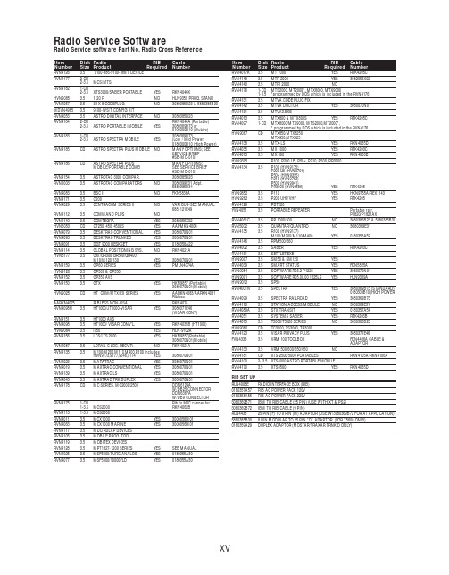
RVN4126 3.59100-386-9100-386/T DEVICERVN41772-CD2-3.5MCS/MTSRVN41821-CD2-3.5XTS3000/SABER PORTABLE YES RKN4046KHVN9085 3.51-20 R NO HLN9359 PROG. STAND RVN4057 3.532 X 8 CODEPLUG NO3080385B23 & 5880385B30 MDVN4965 3.59100-WS/T CONFIG KITRVN4053 3.5ASTRO DIGITAL INTERFACE NO3080385B23RVN41842-CD RKN4046A (Portable) 2-3.5ASTRO PORTABLE /MOBILE YES3080369B73 or0180300B10 (Mobile) RVN41831-CD3080369B732-3.5ASTRO SPECTRA MOBILE YES(Low / Mid Power)0180300B10 (High Power) RVN4185CD ASTRO SPECTRA PLUS MOBILE NO MANY OPTIONS; SEESERVICE BRIEF#SB-MO-0101RVN4186CD ASTRO SPECTRA PLUS MANY OPTIONS;MOBILE/PORTABLE COMB SEE SERVICE BRIEF#SB-MO-0101RVN4154 3.5ASTROTAC 3000 COMPAR.3080385B23RVN5003 3.5ASTROTAC COMPARATORS NO3080399E31 Adpt.5880385B34RVN4083 3.5BSC II NO FKN5836ARVN4171 3.5C200RVN4029 3.5CENTRACOM SERIES II NO VARIOUS-SEE MANUAL6881121E49RVN4112 3.5COMMAND PLUS NORVN4149 3.5COMTEGRA YES3082056X02HVN6053CD CT250, 450, 450LS YES AAPMKN4004RVN4079 3.5DESKTRAC CONVENTIONAL YES3080070N01RVN4093 3.5DESKTRAC TRUNKED YES3080070N01RVN4091 3.5DGT 9000 DESKSET YES0180358A22RVN4114 3.5GLOBAL POSITIONING SYS.NO RKN4021AHVN8177 3.5GM/GR300/GR500/GR400M10/M120/130YES3080070N01RVN4159 3.5GP60 SERIES YES PMLN4074AHVN9128 3.5GP300 & GP350RVN4152 3.5GP350 AVSRVN4150 3.5GTX YES HKN9857 (Portable)3080070N01(Mobile) HVN9025CD HT CDM/MTX/EX SERIES YES AARKN4083/AARKN4081RiblessAARKN4075RIBLESS NON-USA RKN4074RVN4098H 3.5HT1000/JT1000-VISAR YES3080371E46(VISAR CONV)RVN4151 3.5HT1000 AVSRVN4098 3.5HT1000/ VISAR CONV’L.YES RKN4035B (HT1000) HVN9084 3.5i750YES HLN-9102ARVN4156 3.5LCS/LTS 2000YES HKN9857(Portable)3080070N01(Mobile) RVN4087 3.5LORAN C LOC. RECV’R.NO RKN4021ARVN4135 3.5M100/M200,M110,M400,R100 includesHVN9173,9177,9646,9774YES3080070N01RVN4023 3.5MARATRAC YES3080070N01RVN4019 3.5MAXTRAC CONVENTIONAL YES3080070N01RVN4139 3.5MAXTRAC LS YES3080070N01RVN4043 3.5MAXTRAC TRK DUPLEX YES3080070N01RVN4178CD MC SERIES, MC2000/2500DDN6124AW/DB25 CONNECTORDDN6367AW/DB9 CONNECTOR RVN41751-CD Rib to MIC connector 1-3.5MCS2000 RKN4062BRVN41131-3.5MCS2000RVN4011 3.5MCX1000YES3000056M01RVN4063 3.5MCX1000 MARINE YES3000056M01RVN4117 3.5MDC/RDLAP DEVICESRVN4105 3.5MOBILE PROG. TOOLRVN4119 3.5MOBITEX DEVICESRVN4128 3.5MPT1327-1200 SERIES YES SEE MANUALRVN4025 3.5MSF5000/PURC/ANALOG YES0180355A30RVN4077 3.5MSF5000/10000FLD YES0180355A30RVN4017K 3.5MT 1000YES RTK4205CRVN4148 3.5MTR 2000YES3082056X02RVN4140 3.5MTRI 2000NORVN41761-CD MTS2000, MT2000*, MTX8000, MTX90001-3.5*programmed by DOS which is included in the RVN4176RVN4131 3.5MTVA CODE PLUG FIXRVN4142 3.5MTVA DOCTOR YES3080070N01RVN4131 3.5MTVA3.EXERVN4013 3.5MTX800 & MTX800S YES RTK4205CRVN4097 1-CD MTX8000/MTX9000,MTS2000,MT2000*,* programmed by DOS which is included in the RVN4176HVN9067CD MTX850/MTX8250MTX950,MTX925RVN4138 3.5MTX-LS YES RKN4035DRVN4035 3.5MX 1000YES RTK4203CRVN4073 3.5MX 800YES RKN4006BHVN9395 P100, P200 LB, P50+, P210, P500, PR3000RVN4134 3.5P100 (HVN9175)P200 LB (HVN9794)P50+ (HVN9395)P210 (HVN9763)P500 (HVN9941)PR3000 (HVN9586)YES RTK4205HVN9852 3.5P110YES HKN9755A/REX1143 HVN9262 3.5P200 UHF/VHF YES RTK4205RVN4129 3.5PDT220YVN4051 3.5PORTABLE REPEATER Portable rptr.P1820/P1821AXRVN4061C 3.5PP 1000/500NO3080385B23 & 5880385B30 RVN5002 3.5QUANTAR/QUANTRO NO3O80369E31RVN4135 3.5R100 (HVN9177)M100/M200/M110/M400YES0180358A52RVN4146 3.5RPM500/660RVN4002 3.5SABER YES RTK4203CRVN4131 3.5SETTLET.EXEHVN9007 3.5SM50 & SM120YESRVN4039 3.5SMART STATUS YES FKN5825AHVN9054 3.5SOFTWARE R03.2 P1225YES3080070N01HVN9001 3.5SOFTWARE R05.00.00 1225LS YES HLN9359AHVN9012 3.5SP50RVN4001N 3.5SPECTRA YES3080369B73 (STANDARD)0180300B10 (HIGH POWER) RVN4099 3.5SPECTRA RAILROAD YES3080369B73RVN4110 3.5STATION ACCESS MODULE NO3080369E31RVN4089A 3.5STX TRANSIT YES0180357A54RVN4051 3.5SYSTEMS SABER YES RTK4203BRVN4075 3.5T5600/T5620 SERIES NO3080385B23HVN9060CD TC3000, TS3000, TR3000RVN4123 3.5VISAR PRIVACY PLUS YES3080371E46FVN4333 3.5VRM 100 TOOLBOX FKN4486A CABLE &ADAPTORRVN4133 3.5VRM 500/600/650/850NORVN4181CD XTS 2500/5000 PORTABLES RKN4105A/RKN4106A RVN41002- 3.5XTS3000 ASTRO PORTABLE/MOBILERVN4170 3.5XTS3500YES RKN4035DRIB SET UPRLN4008E RADIO INTERFACE BOX (RIB)0180357A57RIB AC POWER PACK 120V0180358A56RIB AC POWER PACK 220V3080369B71IBM TO RIB CABLE (25 PIN) (USE WITH XT & PS2)3080369B72IBM TO RIB CABLE (9 PIN)RLN443825 PIN (F) TO 9 PIN (M) ADAPTOR (USE W/3080369B72 FOR AT APPLICATION) 5880385B308 PIN MODULAR TO 25 PIN ”D” ADAPTOR (FOR T5600 ONLY)0180359A29DUPLEX ADAPTOR (MOSTAR/TRAXAR TRNK’D ONLY)Item Disk Radio RIB Cable Number Size Product Required Number Item Disk Radio RIB Cable Number Size Product Required NumberUtilizing your personal computer, Radio Service Software (RSS)/Customer Programming Software (CPS)/CustomerConfiguration Software (CCS) enables you to add or reprogram features/parameters as your requirements change. RSS/CPS/CCS is compatible with IBM XT, AT, PS/2 models 30, 50, 60 and 80.Requires 640K RAM. DOS 3.1 or later. Consult the RSS users guide for the computer configuration and DOS requirements. (ForHT1000, MT/MTS2000, MTX838/8000/9000, Visar and some newer products —IBM model 386, 4 MEG RAM and DOS 5.0 or higher are recommended.) A Radio Interface Box (RIB) may be required as well as the appropriate cables. The RIB and cables must be ordered separately.Licensing:A license is required before a software (RVN) order is placed. The software license is site specific (customer number and ultimate destination tag). All sites/locations must purchase their own software.Be sure to place subsequent orders using the original customer number and ship-to-tag or other licensed sites; ordering software without a licensed customer number and ultimate tag may result in unnecessary delays. To obtain a no charge license agreement kit, order RPX4719. To place an order in the U.S. call 1-800-422-4210. Outside the U.S., FAX 847-576-3023.Subscription Program:The purchase of Radio ServiceSoftware/Customer Programming/Customer ConfigurationSoftware (RVN & HVN kits) entitles the buyer/subscriber to three years of free upgrades. At the end of these three years, the sub-scriber must purchase the same Radio Service Software kit to receive an additional three years of free upgrades. If the sub-scriber does not elect to purchase the same Radio Service Software kit, no upgrades will be sent. Annually a subscription status report is mailed to inform subscribers of the RSS/CPS/CCS items on our database and their expiration dates.Notes:1)A subscription service is offered on “RVN”-Radio Service Software/Customer Programming/Customer Configuration Software kits only.2)“RVN” software must only be procured through Radio Products and Services Division (RPSD). Software not procured through the RPSD will not be recorded on the subscription database; upgrades will not be mailed.3)Upgrades are mailed to the original buyer (customer number & ultimate tag).4)SP software is available through the radio product groups.The Motorola General Radio Service Software Agreement is now available on Motorola Online. If you need assistance please feel free to submit a “Contact Us” or call 800-422-4210.SMART RIB SET UPRLN1015D SMART RIB0180302E27 AC POWER PACK 120V 2580373E86 AC POWER PACK 220V3080390B49SMARTRIB CABLE (9 PIN (F) TO 9 PIN (M) (USE WITH AT)3080390B48SMARTRIB CABLE (25 PIN (F) TO 9 PIN (M) (USE WITH XT)RLN4488ASMART RIB BATTERY PACKWIRELESS DATA GROUP PRODUTS SOFTWARERVN4126 3.59100-386/9100T DEVICES MDVN4965 3.59100-WS/T CONFIG’TN RVN41173.5MDC/RDLAP DEVICESPAGING PRODUCTS MANUALS6881011B54 3.5ADVISOR6881029B90 3.5ADVISOR ELITE 6881023B20 3.5ADVISOR GOLD 6881020B35 3.5ADVISOR PRO FLX 6881032B30 3.5BR8506881032B30 3.5LS3506881032B30 3.5LS5506881032B30 3.5LS7506881033B10 3.5LS9506881035B20 3.5MINITOR III8262947A15 3.5PAGEWRITER 20008262947A15 3.5PAGEWRITER 2000X 6881028B10 3.5TALKABOUT T3406881029B35 3.5TIMEPORT P7308262947A15 3.5TIMEPORT P930NLN3548BUNIVERSAL INTERFACE KITItem Disk Radio NumberSize Product。
AEC_Q002_Rev_A

AEC - Q002 Rev AAugust 25, 2000GUIDELINESFORSTATISTICAL YIELDANALYSISComponent Technical CommitteeAutomotive Electronics CouncilAEC - Q002 Rev AAugust 25, 2000 Automotive Electronics CouncilComponent Technical CommitteeAcknowledgmentAny document involving a complex technology brings together material and skills from many sources. The Automotive Electronics Council would especially like to recognize the following significant contributors to the development of this revision of this document:Majdi Mortazavi DaimlerChrysler (256)464-2249 msm11@Brian Jendro DaimlerChrysler (256)464-2980 bj5@Robert V. Knoell Visteon Corporation (313)248-1116 rknoell@Gerald E. Servais Delphi Delco Electronics Systems (765)451-7923 gerald.e.servais@Kevin Hankins Delphi Delco Electronics Systems (765)451-7670 kevin.t.hankins@Nick Lycoudes Motorola (408)413-3343 raqa01@Philippe Briot PSA, Peugeot, Citroën 33 01 41 36 7849 p-briot@calvanet.calvacom.frMark Gabrielle On Semiconductor (602)244-3115 mark.gabrielle@Component Technical CommitteeGUIDELINES FOR STATISTICAL YIELD ANALYSIS Text enhancements and changes made since the last revision of thisdocument are shown as underlined areas1.SCOPEThis guideline is intended for use as a method for detecting and removing abnormal lots of material and thus ensuring the quality and reliability of the ICs supplied as meeting AEC - Q100 or 101. The principles described in this guideline are applicable to packaged or unpackaged die.1.1PurposeThis guideline describes a method, utilizing statistical techniques, of identifying a wafer, wafer lot or assembly lot that exhibits an unusually low yield or an unusually high bin failure rate. Experience has shown that wafer and assembly lots exhibiting these abnormal characteristics tend to havegenerally poor quality and can result in significant system reliability and quality problems.Note: For best statistical yield limits (SYL) and statistical bin limits (SBL) results, use test limitsbased on PAT Limits as described in AEC Q001.1.2 ReferencesAEC - Q001 Guidelines For Part Average TestingAEC - Q100 Stress Test Qualification For Integrated CircuitsAEC - Q101 Stress Test Qualification For Discrete Semiconductors2.DEFINITIONS2.1PAT LimitsPart average test limits established per AEC - Q001.3.METHOD FOR ESTABLISHING STATISTICAL YIELD LIMITS (SYL) AND STATISTICAL BINLIMITS (SBL)3.1Detailed Description For Basic Wafer / Wafer Lot / Assembly Lot Level Yield LimitsCollect data from at least six lots and determine the mean and sigma value for the percentage ofdevices passing per lot and the percentage of devices failing each bin-out per lot (lot as used here could mean each wafer, a wafer lot or an assembly lot). Early in production of a part, when dataComponent Technical Committeefrom six lots is not available, data from characterization/matrix lots may be used. This data shallbe updated as soon as production data is available. This early data shall be reviewed and updated using current data at least every 30 days during the first 6 months of production. The current data used shall include the data available since the last update or at least the last 8 lots. Older data shall not be used. After the first 6 months of production the limits shall be updated on a quarterly (every3 months) basis. With this data determine the SYL and SBL (both on a wafer, wafer lot andassembly lot basis) as follows:SYL1 = Mean - 3 SigmaSBL1 = Mean + 3 SigmaSYL2 =Mean - 4 SigmaSBL2 = Mean + 4 SigmaAny wafer or lots that fall below SYL1 or exceed SBL1 shall be held for engineering review. Inaddition, lots that fall below SYL2 or exceed SBL2 may be impounded and require customernotification before release, if specified in the applicable procurement document. Analysis shall be performed on failures to determine the failure mechanism(s) causing these abnormal failure rates.3.2RecordsThe supplier shall maintain records on all wafers, wafer lots and assembly lots that fall below SYL1 or exceed SBL1. This data shall include the root cause for the yield problem and corrective action taken to prevent reoccurrence of the problem. It should also include any special testing or screens that were performed on the wafer, wafer lot or assembly lot and the customer that approved theshipment of the parts in question.4. CUSTOMER NOTIFICATION4.1Procedure For Customer NotificationBefore the customer is notified, the supplier shall have determined the failure mechanism(s) and,based on his experience, determine the corrective action required to prevent a reoccurrence of the condition in future product. The supplier shall also present data on a reasonable expectation of the seriousness of the failure mechanism(s) and it’s impact on quality and reliability. Included in this data should be a plan for additional tests and screens which could provide the user with reasonable certainty that the product he receives will be at least equal to normal product.4.2Customer ResponseThe customer reserves the right to reject material that falls below SYL2 or exceeds SBL2 if thesupplier data does not satisfy his concerns about the quality and reliability of the product.4.3 If Customer Is Not KnownIf the supplier does not know who the customer is and customer approval can not be obtained, the parts from the lots in question (lots falling below SYL2 or exceeding SBL2) shall not be supplied to distributors as meeting AEC - Q100 or Q101.Component Technical CommitteeRevision HistoryRev #Date of change Brief summary listing affected paragraph-July 31, 1997Initial releaseA Aug. 25, 2000Added Paragraph 1.2, Paragraph 1, 2.1, and 4.3 revised.。
Orbi 4G LTE Advanced WiFi 路由器说明书
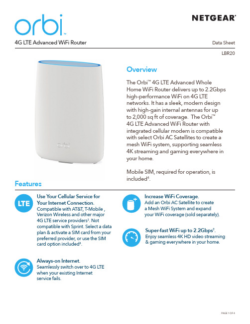
Data SheetLBR20 4G LTE Advanced WiFi RouterOverviewThe Orbi™ 4G LTE Advanced WholeHome WiFi Router delivers up to 2.2Gbpshigh-performance WiFi on 4G LTEnetworks. It has a sleek, modern designwith high-gain internal antennas for upto 2,000 sq ft of coverage. The Orbi™4G LTE Advanced WiFi Router withintegrated cellular modem is compatiblewith select Orbi AC Satellites to create amesh WiFi system, supporting seamless4K streaming and gaming everywhere inyour home.Mobile SIM, required for operation, isincluded4.FeaturesAlways-on Internet. Seamlessly switch over to 4G LTE when your existing Internet service fails.Super-fast WiFi up to 2.2Gbps†. Enjoy seamless 4K HD video streaming & gaming everywhere in your home. Increase WiFi Coverage.Add an Orbi AC Satellite to createa Mesh WiFi System and expand your WiFi coverage (sold separately).Use Your Cellular Service f or Your Internet Connection. Compatible with AT&T, T-Mobile , Verizon Wireless and other major 4G LTE service providers3. Not compatible with Sprint. Select a data plan & activate a SIM card from your preferred provider, or use the SIM card option included4.Data SheetLBR204G LTE Advanced WiFi RouterHouse DiagramGet Startedwith the Orbi appUse the Orbi app to setupand manage your Orbi WiFi. Available on Google Play ™ and Apple ® App Store.NETGEAR Armor empowers you to eliminatevulnerabilities or simply know the status of your home network and devices, anytime, anywhere. Get instant notifications when malicious threats are detected, block unknown devices from joining your home network or take action on vulnerabilities as they are discovered easily through the Orbi App.Better WiFi. Anywhere.Data SheetLBR204G LTE Advanced WiFi RouterLTE antenna connector (not included)LTE antenna connector (not included)WAN/LAN1 and LAN2 portsLTE NanoSIM cardSyncOrbi 4G LTE Advanced WiFi Router (LBR20)Data SheetLBR204G LTE Advanced WiFi RouterThis product comes with a limited warranty that is valid only if purchased from a NETGEAR authorized reseller. /warranty* 90-day complimentary technical support following purchase from a NETGEAR authorized reseller.** Orbi AC Satellites sold separately.†M aximum wireless signal rate derived from IEEE 802.11 specifications. Actual data throughput and wireless coverage will vary and be lowered by network and environmental conditions, including network traffic volume, device limitations, and building construction. NETGEAR makes no representations or warranties about this product’s compatibility with future standards. Up to 2,200Mbps wireless speeds achieved when connecting to other 802.11ac 2,200Mbps devices.‡Actual LTE speed may vary depending on network conditions and Internet data plans.1 NETGEAR Armor ™ is free during the trial period. A yearly subscription, after the trial period, protects all of your connected devices. Visit /armor2 Circle ® includes the Free Basic Plan. Fees apply for a Premium Plan. Visit /circle for more information.3 Network must support subset of the 4G LTE Bands listed under the T echnical Specifications.4Fees apply based on data service plan selected.For regulatory compliance information, visit /about/regulatoryFor indoor use only.NETGEAR, the NETGEAR Logo, NETGEAR Armor, and Orbi are trademarks of NETGEAR, Inc. Apple and the Apple logo are trademarks of Apple Inc., registered in the U.S. and other countries. App Store is a service mark of Apple Inc., registered in the U.S. and other countries. Google Play and the Google Play logo are trademarks of Google LLC. Any other trademarks mentioned herein are for reference purposes only. © 2021 NETGEAR, Inc.NETGEAR, Inc. 350 E. Plumeria Drive, San Jose, CA 95134-1911 USA , /supportD-NA-LBR20-1Technical Specifications• Orbi AC2200 LTE WiFi Router (866 + 866 + 400Mbps)†• AC2200 Simultaneous Tri-band WiFi*******************:Supports256-QAM - 866Mbps — 2x2 @ 5GHz: Supports 256-QAM - 866Mbps — 2x2 @ 5GHz: Supports 256-QAM • IEEE ® 802.11a/b/g/n/ac • LTE Cat 18 up to 1.2Gbps ‡• NA - 4G band (LTE-FDD): B2,4,5,7,12,13,14,17,25, 26,29,30,66,71- 4G band (LTE-TDD): B41 - 3G band: B2,4,5Physical Specifications• Dimensions: 6.7 x 3.1 x 8.9 in (170 x 79 x 226 mm)• Weight: 1.72 lb (0.78 kg)What’s In the Box?• One (1) Orbi 4G LTE Advanced WiFi Router (LBR20)• One (1) 2m Ethernet cable• One (1) 12V/2.5A power adapter • Quick start guide• Third party SIM card & activation instructionsWhat Do I Need for Orbi to Work?• High-speed Internet connection • Activated LTE SIM card • Orbi app • D O NOT purchase a second Orbi Router if you need to expand your WiFi coverage • T o expand your Orbi WiFi system, purchase an Orbi AC Satellite (RBS50, RBS50Y, RBS40, RBS40V, RBW30 or RBS20), sold separately, for additional WiFi coverage• EU & AU- 4G band (LTE-FDD): B1,3,5,7,8,20,28 - 4G band (LTE-TDD): B38,40,41 - 3G band: B1,3,5,8• MU-MIMO capable for simultaneous data streaming• Implicit & Explicit Beamforming for 2.4GHz & 5GHz bands • T wo (2) 10/100/1000Mbps Gigabit Ethernet ports - O ne (1) WAN/LAN & one (1) LAN • T wo (2) External LTE antenna connectors (antennas not included)• Security - C omprehensive anti-virus & data theft protection for your PC, Mac ® and mobile devices with NETGEAR Armor ™ - S tandards-based WiFi Security (802.11i, 128-bit AES encryption with PSK) - G uest WiFi Network is easy to setup separate & secure Internet access for guests • Voice Control- Amazon Alexa™- The Google © Assistant• C ircle ® — Smart Parental Controls to manage content and time online for all your devices. Learn more at /circle。
- 1、下载文档前请自行甄别文档内容的完整性,平台不提供额外的编辑、内容补充、找答案等附加服务。
- 2、"仅部分预览"的文档,不可在线预览部分如存在完整性等问题,可反馈申请退款(可完整预览的文档不适用该条件!)。
- 3、如文档侵犯您的权益,请联系客服反馈,我们会尽快为您处理(人工客服工作时间:9:00-18:30)。
a r X i v :a s t r o -p h /9708195v 1 21 A u g 1997Mon.Not.R.Astron.Soc.000,1–??(1997)Printed 1February 2008(MN La T E X style file v1.4)Nova V1425Aquilae 1995-The Early Appearance ofAccretion Processes in An Intermediate Polar CandidateA.Retter ∗,E.M.Leibowitz and O.Kovo-KaritiSchool of Physics and Astronomy and the Wise Observatory,Raymond and Beverly Sackler Faculty of Exact Sciences,Tel-Aviv University,Tel Aviv,69978,Israel ∗email:alon@wise.tau.ac.ilsubmitted 1997April 10ABSTRACTContinuous CCD photometry of Nova Aquilae 1995was performed through the standard B,V,R and I filters during three nights in 1995and with the I filter during 18nights in 1996.The power spectrum of the 1996data reveals three periodicities in the light curve:0.2558d,0.06005d and 0.079d,with peak-to-peak amplitudes of about 0.012,0.014and 0.007mag.respectively.The two shorter periods are absent from the power spectrum of the 1995light curve,while the long one is probably already present in the light curve of that year.We propose that V1425Aql should be classified as an Intermediate -Polar CV.Accordingly the three periods are interpreted as the orbital period of the underlying binary system,the spin period of the magnetic white dwarf and the beat period between them.Our results suggest that no later than 15months after the outburst of the nova,accretion processes are taking place in this stellar system.Matter is being transferred from the cool component,most likely through an accretion disc and via accretion columns on to the magnetic poles of the hot component.Key words:accretion,accretion discs -novae,cataclysmic variables -stars:individuals:Nova Aquilae 1995-magnetic fields -polarization1INTRODUCTION 1.1V1425AquilaeNova Aql 1995was discovered on 1995February 7by Takamizawa (1995).Mason et al.(1996)used its similar-ity to Nova V1668Cygni 1978to extrapolate a maximum brightness of M V ≈6.2and t 2V ≈11d.This classifies Nova Aquilae as a fast one.They also deduces from IR consid-erations that the dust shell of the nova was optically thin shortly after its outburst.The probable precursor star of about 20mag.was detected by Skiff(1995)and this indi-cates an outburst amplitude of about 14mag.Retter,Leibowitz &Kovo-Kariti (1996)and Leibowitz,Retter &Kovo-Kariti (1997)reported the discovery of two photometric periods in the light curve of Nova Aquilae 1995,and pointed out the resemblance of this object to Interme-diate Polars systems.In this work we present further argu-ments for our interpretation of the periods of V1425Aql as resulting from the Intermediate Polar nature of the nova.1.2Intermediate Polars and nova systemsIntermediate polars (for reviews see Patterson 1994,Hellier 1995,1996,1997)are binary systems,which are a sub-class of AM Her stars (magnetic Cataclysmic Variables).Unlike in other members of the AM Her class,in Intermediate Polars the rotation of the primary white dwarf is not synchronized with the orbital motion of the binary system.The spin pe-riods found in Intermediate Polars are usually much shorter than their orbital periods (Patterson 1994,Hellier 1996).One of the main observational characteristics of Inter-mediate Polars is the presence of multiple periodicities in the power spectra of their light curves,emanating from the non-synchronous rotation of the primary with the orbital revolution.In fact this characteristic has become,together with modulations of the X-ray radiation of the system,a major criterion for membership in the Intermediate Polar group.The classification of a classical nova as an Intermediate Polar is not new.DQ Her is a prototype of a nova which is an Intermediate Polar (Patterson 1994),and in the lastc1997RAS2 A.Retter,E.M.Leibowitz and O.Kovo-Kariti few years a few other novae have been so classified as well. Examples are V533Her and GK Per,with white dwarf spin periods of64and351sec,respectively(Patterson1994).The detected variations of V603Aql in the optical,X-ray and ul-traviolet regimes make it also a likely Intermediate Polar sys-tem(Udalski&Schwarzenberg-Czeny1989,Schwarzenberg-Czeny,Udalski&Monier1992).The presence of multiple periods in the light curve of HZ Pup supports the mem-bership of this nova in the Intermediate Polar group,too (Abbott&Shafter1997).In V1974Cygni,evidence was found to the presence of an accretion disc in the system, (Retter,Ofek&Leibowitz1995,Retter,Leibowitz&Ofek 1996,1997a,1997b,1997c,Skillman et al.1997),togetherwith some indications for an intense magneticfield on the surface of the white dwarf(Chochol et al.1997).The com-bination of these two properties makes V1974Cyg another potential candidate for the Intermediate Polar group.It would therefore appear that the Intermediate Polar phenomenon is not uncommon among classical nova CV sys-tems.2OBSER V ATIONSWe observed Nova Aquilae during three nights in1995May,and18nights during the interval1996April–August.Ta-ble1presents a summary of the observations schedule.We used the Tecktronix1K CCD camera,described in Kaspi etal.(1995)mounted on the1-m telescope at the Wise Obser-vatory.During the observations in1995we switched succes-sively between the standard B,V,R and Ifilters,and in1996 the photometry was carried out only in the I band.We note that our Ifilter is slightly redder than the standard band-pass.The exposures times of the observations in1995were 30sec.(I),40(R),50(V)and60(B)with a repetition time of about250sec.In1996the integration time was180sec. The number of frames obtained in our programme in1995 and1996are522and1170,respectively.Photometric measurements wereperformed using the DAOPHOT program(Stetson1987).An IRAF⋆script was written by thefirst author for automatic reduction with aperture photometry.We chose star radii offive pixels,cor-responding to angular diameter of about3.5arcseconds.In-strumental magnitude of the nova,as well as of a few dozens reference stars,depending on the image quality,were ob-tained from each frame.Wefinally used the Wise Observa-tory reduction program DAOSTAT(Netzer et al.1996)for an internal consistent series of the nova magnitudes.Fig.1displays a comprehensive visual light curve of the nova from discovery to1996September.The data were taken from AFOEV†.The marks in thefigure indicate the times of our observations.Fig.2presents the1996I light curve of the nova,as measured in our observing programme.One can see that⋆IRAF(Image Reduction and Analysis Facility)is distributed by the National Optical Astronomy Observatories,which are op-erated by AURA,Inc.,under cooperative agreement with the National Science Foundation.†AFOEV(Association Francaise des Observateurs d’Etoiles Variables)operates at Strasbourg Astronomical Data Center (CDS),France.Table1.The observations time tableUT Time of Start Run Time Points Filters Date(JD+2449000)(hours)number 100595848.410 4.5146B,V,R,I 110595849.403 4.5202B,V,R,I 120595850.408 4.5174B,V,R,I 2804961202.497 2.341I 2904961203.496 1.317I 1005961214.493 1.932I 1105961215.6370.24I 3005961234.419 3.859I 3105961235.373 2.647I 010*******.393 4.582I 3107961296.256 5.9103I 010*******.234 6.7120I 020*******.252 6.496I 0308961299.2387.2115I 2108961317.251 4.580I 2208961318.238 4.070I 2308961319.283 4.035I 2708961323.234 4.362I 2908961325.244 4.379I 3008961326.224 4.270I 3108961327.245 4.358IJULIAN DATE (+2400000)161412108VISUALMAGNITUDEFigure 1.Two years light curve of Nova Aql1995.Data points are visual estimates of amateur astronomers,compiled by AFOEV†.The times of our observations are marked.c 1997RAS,MNRAS000,1–??V1425Aql -Intermediate Polar Candidate3HJD (+2450000)20.420.220.019.819.619.4I N S T R U M E N T A L M A G N I T U D EFigure 2.All the 1996I magnitudes of V1425Aql that are pre-sented in this work.The brightness of the nova decreased by about 0.6mag.during the time interval of these observations.during the time interval spanned by the observations in 1996,the nova declined by about 0.6mag.A much faster decrease in the brightness of the system (almost four mag.)describes the behaviour of the nova in the I band from 1995May to 1996April.3DATA ANALYSIS3.1The apparent periodicitiesDuring a few of our best nights in 1996,the light curve of the nova exhibits a small sinusoidal-like modulation with a peak-to-peak amplitude of about 1–2per cent on a time scale of 1.5hr.Sometimes a smaller dip at phase 0.5,relative to the main variation,was also seen.However,during most of the nights these variations were hidden in the noise.In a few nights a systematic brightness variation of a time scale of a few hours,with similar amplitude,could be recognized in the light curve as well.The upper panel of Fig.3is a plot of the power spec-trum (Scargle 1982)of most of the I band points in 1996.We omitted from our analysis the night of May 11,because it had only a very few points,and the data points of August 27and 31,when the light of the nova and the comparison stars varied by about 0.1mag,due to reflected moonlight or instrumental problems.The inclusion of these three nights in the analysis doesn’t affect the results in any significant way.Altogether we used 1046points in our time series analysis.Before applying the power spectrum routines we normal-010203040FREQUENCY (CYCLES/DAY)2040P O W E R2040102030402040P1P3P2P21P21P3P1P219951995-61996Figure 3.Upper panel -power spectrum of the I light curve of 15nights in 1996.The peaks marked as P1and P2represent the two major periodicities in the light curve,while peak P21is the first overtone of P2.Each one is at a center of a pattern of peaks corresponding to the 1,1/2,1/3etc.day aliases of the central one.The peak P3is at the beat frequency between P1and P2.Middle panel -power spectrum of the three nights in 1995.The data are a mixture of measurements in four bands.Within the large observational uncertainty,the group of high peaks at the left-hand side of the diagram (being aliases of each other)may be regarded as representing the same periodicity associated with the P1peak in the 1996power spectrum.Lower panel -power spectrum of the combined 1995-6data.The P1peak is significantly higher than in the 1996data,while the other peaks are somewhat lower.ized the data by subtracting the mean magnitude from eachnight.The power spectrum shows three distinct groups of peaks.The left one is around the frequency 3.909d −1,cor-responding to the period P 1=0.2558±0.0001d.The un-certainty interval is a better than 99%confidence limit for the value of the period.It is derived with the Bootstrap technique (Efron &Tibshirani 1993)from a sample of 1000pseudo-observed light curves.The second group near the center of the frame is around the frequency 16.6518d −1,corresponding to the period P 2=0.06005±0.00001d,with the uncertainty derived as for the period P 1.The third group of peaks at the right-hand side of the diagram is centered around the first harmonic of P 2.All three groups are char-acterized by a central frequency and a pattern of peaks on both sides,corresponding to the 1,1/2,1/3etc.day aliases of the central one.We checked the reliability of the three major period-icities in the light curve of the nova by dividing the datac1997RAS,MNRAS 000,1–??4 A.Retter,E.M.Leibowitz and O.Kovo-Karitiinto two distinct parts(thefirst eight nights,and the re-maining seven nights).A similar triple structure appeared in the power spectrum of each part separately.In a different test for the independence of the three periodicities,we sub-tracted from the data the fundamental harmonic of the lower frequency.The other two peaks remained almost unaltered in the power spectrum of the residuals.We repeated this treatment for the other two frequencies and found out that all three are indeed independent of each other.As a further check we created an artificial light curve on the times of the real observations,by superposing a sine wave of one of the three periodicities over a random distribution of points rep-resenting white noise.The power spectrum of each of these three synthetic light curves showed only the corresponding planted periodicity,surrounded by an alias pattern similar to the one of the real data,with no trace of the other peri-odicities.3.2A third PeriodicityIn the power spectrum shown in the upper panel of Fig.3 there is an additional group of peaks that stand out con-siderably above the noise level,although not to the height that makes them statistically significance.The central high-est ones are at the frequency12.70d−1,corresponding to the period P3=0.079d,and its one day alias at the frequency 11.72d−1.If we remove from the data the two periods P1 and P2,represented by the fundamental and thefirst har-monic of the corresponding periodicities,the group of these peaks remains almost unaltered in the power spectrum of the residuals.The frequency of the beat between the P1and the P2 periodicities is12.74d−1,corresponding to the period0.0785 d.The near similarity between this frequency and the P3fre-quency in the power spectrum of the observed data strongly suggests the presence of the beat period in the1996light curve of the nova,in addition to the presence of the peri-ods themselves.The fact that the beat frequency remains present in the power spectrum even after the removal of the other two periodicities indicates that this frequency is indeed modulating the nova light and that it is not a nu-merical artifact of the data reduction of the very unevenly sampled light curve of the system.We can estimate the statistical significance of the P3 peak in the power spectrum in the following way.By the Bootstrap technique on a sample of1000pseudo-light curves,we found that a one Sigma(67%)and a99%un-certainty intervals in the position of the P3in the power spectrum are0.0004and0.001d−1,respectively.Thus it appears that the observed P3peak falls within one Sigma of the expected position of the beat frequency.Applying now again the Bootstrap routine on another sample of1000,we found that the probability of a chance occurrence of a peak as high as the observed one within a99%uncertainty inter-val around the beat frequency is less than0.1%.Thus the combination of the height of the P3peak and the proximity of its position to that of the beat frequency,whose value is known a-priory,once the P1and the P2periods are known, makes the P3peak in the power spectrum a statistically highly significant feature.We therefore conclude that there exists a true third periodicity,the beat of thefirst two ma-PHASE155-5MILLI-AMPLITUDE155-50.00.5 1.0 1.5 2.0155-5Figure4.The Ifilter light curve of15nights in1996,folded on to the three periods and binned into20equal bins.Upper panel —the6.14-h period.Middle panel—the1.44-h periodicity.Lower panel—the1.9-h beat period.jor ones,in the light curve of Nova Aql95during the1996 observations.3.3Structure of the three periodicitiesIn the three panels of Fig.4we show the I band data of the 1996observations folded on to the periods P1,P2and the beat period between them,P3.The points are the average magnitude value in each of40equal bins that cover the0-1 phase interval.The bars are the1σuncertainties in the value of the average values.Solid line represents thefirst two terms in a Fourier expansion around the corresponding fundamen-tal periods,fitted to the data points by Least Squares.The full amplitude of the average variation in the upper curve is0.012mag.,that of P2is0.014mag.and that of the thirdperiodicity at the lower panel is0.007mag.These numbers were derived by binning the folded data into10equal inter-vals and by measuring the difference between the extrema.The error in the amplitude in all three cases is about0.004, and it was calculated by samples of1000Bootstrap simu-lations.The double structure in the P2curve is responsible for the strong appearance of thefirst overtone of this peri-odicity in the power spectrum(Fig.3upper panel).It will be further discussed in section4.The bestfitted ephemeris for the three periodicities are:T1(min)=HJD2450202.566+0.2558E.±0.002±0.0001c 1997RAS,MNRAS000,1–??V1425Aql-Intermediate Polar Candidate5T2(min)=HJD2450202.664+0.06005E.±0.007±0.00001T3(min)=HJD2450202.44+0.079E.±0.01±0.0013.4The1995light curveIn1995we observed the nova in only three nights,each run lasting about4.5hr.In these observations we used the four standardfilters-B,V,R and I in a sequence.Inspecting the four light curves by eye wefind no clear short scale variations of the order of1.5hr.The light curves do show,however, a long term variation,on time scale of the duration of the runs,i.e.of a few hours.The four power spectra of the bands (not shown here)have a few peaks,corresponding to periods of a few hours,all of them are,however,statistically nearly insignificant.In order to improve the significance of the peaks in the power spectrum,we combined the four bands together and formed a united colour power spectrum.This was done by subtracting the mean from the points of eachfilter at the three nights,and then sorting the data by time.The power spectrum of the resulting light curve is shown at the middle panel of Fig.3.The pattern of1-d alias peaks at the left-hand side of the diagram,which is manyσabove the noise level,includes the frequency4.01±0.17d−1.Due to the scarcity of the1995data,the small amplitude of the varia-tion(0.010±0.006mag.)and the rather short duration of the observations in each night,the uncertainty in the posi-tion of this pattern of peaks on the frequency axis is large. Within this uncertainty it is consistent with the lower fre-quency peak(P1)in the power spectrum of the1996data. In the1995power spectrum,however,there is no trace of the shorter periodicities identified in the1996data.With the Bootstrap technique we found on a sample of1000pseudo-light curves,that the probability to obtain anywhere in the power spectrum a pattern of peaks as high as the observed ones is smaller than0.1%.As a more severe test we checked also the probability to obtain peaks as high as the observed ones in data of correlated magnitudes.For that purpose we planted on the times of our real observations in each night a sinusoidal modulation with periods randomly chosen between4–8hr.This test shows that the observed pattern of peaks is significant at a99%confidence level.We also combined the data of1995with the1996points. In the power spectrum of the combined light curve(Fig. 3lower panel),the peaks around P1gain a considerable amount of power.In particular the power at this frequency increases from∼35in the1996data to∼45in the combined 1995/96data.This increase should be compared with a small decrease in the power in the other periodicities of1996.For comparison we also combined with the1996data a pseudo 1995light curve,namely,random magnitudes,distributed over the times of observations in1995.No increase in power at the P1frequency is obtained in the power spectrum of this light curve,nor in the power spectrum of a light curve in which we added to the1996data a noisy Sine wave of other periods that is planted on the1995times of observation.We may summarize that while the1995observations are too scarce for establishing by themselves the presence of a few hours periodicity in the light curve,much less for determining its value,the data do suggest that the6.14-h period identified in the1996light curve had already existed in the1995light curve.The1.44-h periodicity and itsfirst harmonic,as well as the beat period,do not seem to be present in the1995data.4DISCUSSION4.1Identification of the two periodsThree periodicities have been identified in the light curve of V1425Aql15months after its outburst;one of them,P1, was present in the light curve already three months after outburst.The three periods reflect three genuine modula-tions of the light emanating from this stellar system.They are not independent of each other as one of them is the beat between the other two.Thus it appears that in1996two independent clocks are operating in the nova system,each one modulates the light radiation directly and also indirectly through some combination with the other clock.We suggest that the longest periodicity,P1∼6.14h, is the orbital period of the nova underlying binary system. This is based mainly on the fact that this period was present in the light curve already in1995,with no apparent change in its value.The observations by Mason et al.(1996),and their conclusion,that the dust shell of the nova was not op-tically thick at the time of their and our observations,make it indeed likely that the binary system could have been seen with optical light at that time.Radial velocity measurements should confirm or refute our suggestion.The amplitude of the6.14-h variation,if indeed present in the1995light curve,is comparable,in magnitude units, to the amplitude of this variation in1996.In1996,however, the optical brightness of the system was some four mag. fainter than in1995.This seems to us to suggest that the major source of the binary modulation in the light curve is the reflection effect.The amplitude of modulations by this effect depends on the inclination angle of the system and on the fraction of the radiation from the hot component,that is being intercepted by the companion,and reflected in the direction of the observer.Thefirst parameter is clearly an invariant of the system.The second one may also be con-stant tofirst order,provided that the dimensions of the hot component did not change appreciably,relative to the radius of the companion,between the two years.This could be the case either because the size of the hot source,indeed did not change by a large factor from1995to1996,or because in 1995,the size of the hot source,e.g.the white dwarf or the pseudo-photosphere of the white dwarf,was already small relative to the radius of the secondary star.We further propose that Nova Aql95is an Intermedi-ate Polar,in which the shorter period,P2,is the spin pe-riod of the magnetic white dwarf in the system.Spin pe-riod that is shorter than the orbital is the rule in almost all known Intermediate Polars.There is only one excep-tion,RX J19402-1025,but this is a nearly synchronous sys-tem,in which the spin period has only a marginal excess: (P spin−P orbital)/P orbital∼0.3%(Patterson et al.1995).The double structure shape of the86.5-m period(Fig.c 1997RAS,MNRAS000,1–??6 A.Retter,E.M.Leibowitz and O.Kovo-Kariti4middle panel)is typical to the variations emanating from one pole of a rotating magnetic white dwarf(Warner1995). This evidence supports the interpretation of this period as the spin period of the white dwarf.Finally,the third period is interpreted as the beat pe-riod between the two other periods.Its independent presence in the light curve of Intermediate Polar system is well estab-lished,observationally as well as in theory(Patterson1994, Hellier1995,1996,1997).4.2The accretion form–an Accretion Disc(?) The fate of the accretion disc in a classical nova binary sys-tem during the outburst event and immediately following it is unclear.It is sometimes assumed that if an accretion disc is present in the pre-outburst system,it is being destroyed by this cataclysmic event.However,no theoretical effort was done in the direction of answering the question when is the accretion disc rebuilt in the shattered,slowly decaying sys-tem.Up to recent times there were little observational data concerning the existence of the accretion disc in young no-vae.In the last few years,however,observational data are being accumulated,indicating an early presence of an ac-cretion disc in a few classical novae,already a few weeks or months after the outburst.Leibowitz et al.(1992)discov-ered an eclipse three weeks after maximum light in Nova V838Herculis1991.They interpreted it as the occultation of the accretion disc by the secondary star.Some30months after the outburst of the classical nova V1974Cyg,Retter, Leibowitz&Ofek(1997a,1997b,1997c)and Skillman et al. (1997)detected permanent superhumps in the light curve of this system.Superhumps characterize the SU UMa class of CVs that are known to have an accretion disc in their underlying stellar system.Thus the observations in V1974 Cyg indicate the early presence of an accretion disc also in that system.It is now believed that in nearly all known Intermedi-ate Polars,a major part of the accretion proceeds through an accretion disc most of the time(Patterson1994,Hellier 1996).In a few systems the accretion is partly maintained by a different mode-disc overflow,in which the accretion stream from the companion bypasses the accretion disc and interacts directly with the magneticfield of the white dwarf. (Hellier1993,1995,1996,1997,Hellier&Livio1994).How-ever,only one object(RX J1712-24)out of the13Interme-diate Polars listed by Hellier1996(see his Fig.2)is believed to be a disc-less system.Based on this statistics,and ignor-ing the possibility that it is biased by a selection effect due to the excessive brightness of the disc,we may regard it as very likely that no later than1996May,Nova Aql95already contained an accretion disc within its binary system.Unless the asymmetries in the system are large,the rel-ative amplitude of the spin period to the beat period is afirst order measure of the rate of accretion through an accretion disc relative to the rate of accretion via the disc overflow mode(Hellier1997).In N.Aql95,if the86.5-m period is indeed the spin period of the white dwarf,the dominant ac-cretion is via the accretion disc,while a smaller part of it is maintained through the disc overflow mode.This is implied by the(peak-to-peak)amplitude0.007mag.of the beat pe-riod0.079d,that is a half of the amplitude0.014of the 0.06005-d spin period.The86.5-m spin periodicity in V1425Aql is one of the longest among Intermediate Polars(Patterson1994,Hellier 1996),especially if the three nearly synchronous systems (Nova V1500Cygni1975,BY Cam and RX J19402-1025-Patterson et al.1995)are not counted in this class(Warner 1995groups them with the AM Her systems).Hellier(1996) and Allan et al.(1996)speculated that slow rotators accrete through accretion curtains.A86.5-m spin cycle makes Nova Aquilae95a slow rotator and therefore a system with that type of accretion mode.In the accretion curtains model,the pulse structure is expected to consist of a single hump,be-cause the two poles in this mode,act in phase.In the middle panel of Fig.4we see,however,that the pulse in N.Aql95 has a structure of mid-way between one and two humps. According to Hellier,this would indicate that in this system polecaps are modulating the optical radiation to a large ex-tend,in spite of the slow rotation of the white dwarf.If these ideas are correct,it is another evidence for the presence of an accretion disc in the system.According to the spin-amplitude relation of Patterson (1994)the amplitude of the shorter,spin variation should increase as the nova continues to fade.Further confirmation for the Intermediate Polar nature of this system may come also from future X-ray and polarization measurements.4.3Magnetic Novae and Speed ClassIt was proposed by Diaz&Steiner(1991)and by Orio, Trussoni&Ogelman(1992)that classical novae with strong magneticfields tend to be of higher speed class.Ourfind-ings that Nova Aql95is an Intermediate Polar seems to be in line with this suggestion as this nova is a fast one with t2V≈11d(Mason et al.1996).We checked this claim against observational data con-cerning some60classical novae(Warner1995),of which12 are Intermediate Polars or suspected Intermediate Polars. We found that the histograms of both t2and t3parameters of the population of Intermediate Polars novae are not signif-icantly different from the corresponding histograms for the non-magnetic systems.Our test,however,cannot be con-sidered as evidence against the above contention,since the statistic is rather poor due to the still small number of rec-ognized magnetic classical novae.5SUMMARY(1)We found three periods in the power spectrum of Nova Aql1995:0.2558d,0.06005d(with itsfirst harmonic)and 0.079d-the beat period between thefirst two periods. (2)The longer period is seen in the power spectra of the ob-servations in the two years1995and1996,while the other two periodicities are absent from the1995data.(3)The inter-relations among the frequencies of the three periods are characteristics of Intermediate Polar systems. Based on this we suggest that V1425Aquilae belongs to this group.(4)We interpret the longer6.14-h period as the orbital pe-riod of the binary system,the86.5-m period as the spin period of a magnetic white dwarf and the1.9-h period as the beat period between them.(5)These results imply that accretion(probably via anc 1997RAS,MNRAS000,1–??。