UNO-3000G系列模式跳线
UNO 工业级嵌入式控制器 说明书

工业级嵌入式控制器工业自动化领域理想的应用平台,兼具开放性与强固性两大优势/eAutomation电力UNO-2050物流UNO-3072设备管理UNO-2182设备自动化UNO-30741通过全球范围众多领域的应用与持续推进证实,研华UNO系列工业级嵌入式控制器是一款功能强大、品质卓越、理想可靠的应用平台。
通用型设计,扩展丰富UNO交 通UNO-2059车队管理UNO-2176门 禁UNO-1019电力 / 能源UNO-21712可靠的模块设计无风扇设计宽操作温度支持多种安装方式结构紧凑开放的操作系统强大的计算能力3UNO: 开放式架构,坚固,无风扇设计坚固,无风扇设计,无风扇设计研华UNO 系列工业级嵌入式控制器结构坚固耐用,适用于各种关键与恶劣环境。
灵活的扩展功能、可靠的品质以及对恶劣环境的适应,源于研华独特的嵌入式、满足工业应用的设计理念及领先的计算机技术。
如果您正在寻找一款兼具强固性与紧凑性的计算平台,那么拥有工业级设计及内建�/O 的UNO 系列绝对是理想的选择。
UNO不仅是一台IPCUNO-1000系列通讯协议转换、执行输出入控制与数据储存等功能的理想控制器。
中通讯协议转换、执行输出入控制与数据储存等功能的理想控制器。
UNO-2000系列紧凑简便,无风扇嵌入式紧凑简便的随用平台,满足不同的应用需要研华UNO-2000们具有板上集成的此是数据网关和控制器的理想解决方案。
UNO-2100 系列高性能,带现场数据量测,低能耗平台,高性能计算机与通讯器研华UNO-2100可据系统要求选用不同等级展。
可据系统要求选用不同等级PC/104扩展功能支持用户扩充任何第三方UNO-3000系列无风扇、、带设计,带有前出线设计,带有出线设计,带有研华UNO-3000可据系统要求选用不同等级前出线设计。
可据系统要求选用不同等级设计。
可据系统要求选用不同等级出线设计。
可据系统要求选用不同等级1.5GHz)),PC�扩展功能支持用户扩充任何第三方研华UNO系列工业级嵌入式控制器结构坚固耐用,适合在任何关键和恶劣环境中使用。
优利德 UDP3000S 系列 可编程线性电源用户手册说明书
UDP3000S系列可编程线性电源使用说明书前言感谢您购置优利德可编程线性电源,为了确保正确使用本仪器,在操作仪器之前请仔细阅读手册,特别是有关“安全信息”部分。
如已阅读完手册,建议您将此手册妥善保管,以便在将来使用过程中进行查阅。
版权信息UNI-T优利德科技(中国)股份有限公司版权所有。
UNI-T产品受中国或其他国家专利权的保护,包括已取得或正在申请的专利。
本公司保留更改产品规格和价格的权利。
UNI-T保留所有权利。
许可软件产品由UNI-T及其子公司或提供商所有,受国家版权法及国际条约规定的保护。
本文中的信息将取代所有以前出版的资料中的信息。
UNI-T是优利德科技(中国)股份有限公司(Uni-Trend Technology(China) Co.,Ltd)的注册商标。
保修服务仪器自购买之日起保修期壹年,在保修期内由于使用者操作不当而损坏仪器的,维修费及由于维修所引起的费用由用户承担,仪器由本公司负责终身维修。
如果原购买者自购该产品之日一年内,将该产品出售或转让给第三方,则保修期应为自原购买者从UNI-T或授权的UNI-T 分销商购买该产品之日起一年内。
电源线及其他附件和保险丝等不受此保证的保护。
如果在适用的保修期内证明产品有缺陷,UNI-T可自行决定是修复有缺陷的产品且不收部件和人工费用,或用同等产品(由UNI-T决定)更换有缺陷的产品。
UNI-T作保修用途的部件、模块和更换产品可能是全新的,或者经修理具有相当于新产品的性能。
所有更换的部件、模块和产品将成为UNI-T的财产。
以下提到的“客户”是指据声明本保证所规定权利的个人或实体。
为获得本保证承诺的服务,“客户”必须在适用的保修期内向UNI-T通报缺陷,并为服务的履行做适当安排。
客户应负责将有缺陷的产品装箱并运送到UNI-T指定的维修中心,同时预付运费并提供原购买者的购买证明副本。
如果产品要运到UNI-T维修中心所在国范围的地点,UNI-T应支付向客户送返产品的费用。
CommScope OM4 Uniboot 双纤维接线缆说明书
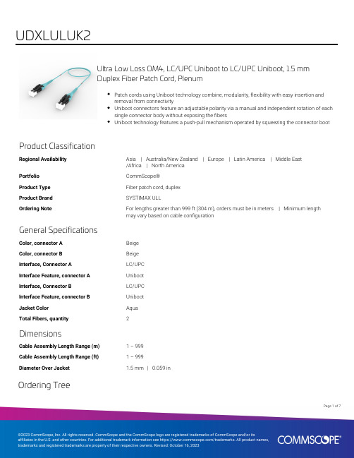
Ultra Low Loss OM4, LC/UPC Uniboot to LC/UPC Uniboot, 1.5 mmDuplex Fiber Patch Cord, PlenumPatch cords using Uniboot technology combine, modularity, flexibility with easy insertion andremoval from connectivityUniboot connectors feature an adjustable polarity via a manual and independent rotation of eachsingle connector body without exposing the fibersUniboot technology features a push-pull mechanism operated by squeezing the connector bootProduct ClassificationRegional Availability Asia | Australia/New Zealand | Europe | Latin America | Middle East/Africa | North AmericaPortfolio CommScope®Product Type Fiber patch cord, duplexProduct Brand SYSTIMAX ULLOrdering Note For lengths greater than 999 ft (304 m), orders must be in meters | Minimum lengthmay vary based on cable configurationGeneral SpecificationsColor, connector A BeigeColor, connector B BeigeInterface, Connector A LC/UPCInterface Feature, connector A UnibootInterface, Connector B LC/UPCInterface Feature, connector B UnibootJacket Color AquaTotal Fibers, quantity2DimensionsCable Assembly Length Range (m) 1 – 999Cable Assembly Length Range (ft) 1 – 999Diameter Over Jacket 1.5 mm | 0.059 inOrdering Tree17Page ofMechanical SpecificationsCable Retention Strength, maximum11.24 lb @ 0 ° | 4.40 lb @ 90 °Optical SpecificationsFiber Mode MultimodeFiber Type OM4, LazrSPEED®Insertion Loss, maximum0.15 dBReturn Loss, minimum35 dBEnvironmental SpecificationsOperating Temperature-10 °C to +60 °C (+14 °F to +140 °F)Environmental Space PlenumRegulatory Compliance/CertificationsAgency ClassificationCHINA-ROHS Above maximum concentration valueISO 9001:2015Designed, manufactured and/or distributed under this quality management system ROHS Compliant/ExemptedUK-ROHSCompliant/ExemptedIncluded Products760251283P-002-DU-5K-M15AQ/AY/LTS–Fiber indoor cable, LazrSPEED® Plenum Light Duty Interconnect Cordage, 2 fiber, MultimodeOM4, Meters jacket marking, Aqua jacket color860660825–LC UniBoot 1.5 mm Multimode Aqua LC UNIBOOT duplex connectorPage of27Page of 37Fiber indoor cable, LazrSPEED® Plenum Light Duty InterconnectCordage, 2 fiber, Multimode OM4, Meters jacket marking, Aqua jacketcolorProduct ClassificationRegional AvailabilityAustralia/New Zealand | EMEA | Latin America | Middle East/Africa | North America PortfolioCommScope®Product TypeFiber indoor cable Product Series P-DUGeneral SpecificationsCable TypeMPO trunk cable Construction TypeNon-armored Subunit TypeGel-free Jacket ColorAqua Jacket MarkingMeters Total Fiber Count 2DimensionsDiameter Over Jacket 1.5 mm | 0.059 inRepresentative ImageMechanical SpecificationsMinimum Bend Radius, loaded 30 mm | 1.181 in20 mm | 0.787 inMinimum Bend Radius, unloaded20 mm | 0.787 inTensile Load, long term, maximum30 N | 6.744 lbfTensile Load, short term, maximum100 N | 22.481 lbfCompression 4 N/mm | 22.841 lb/inCompression Test Method FOTP-41 | IEC 60794-1 E3Impact0.74 N-m | 6.55 in lbImpact Test Method FOTP-25 | IEC 60794-1 E4Strain See long and short term tensile loadsStrain Test Method FOTP-33 | IEC 60794-1 E1Twist10 cyclesTwist Test Method FOTP-85 | IEC 60794-1 E7Optical SpecificationsFiber Type OM4, LazrSPEED®Environmental SpecificationsInstallation temperature0 °C to +70 °C (+32 °F to +158 °F)Operating Temperature0 °C to +70 °C (+32 °F to +158 °F)Storage Temperature-40 °C to +70 °C (-40 °F to +158 °F)Cable Qualification Standards Telcordia GR-409Environmental Space PlenumFlame Test Listing NEC OFNP (ETL) and c(ETL)Flame Test Method NFPA 130 | NFPA 262Environmental Test SpecificationsHeat Age0 °C to +85 °C (+32 °F to +185 °F)Heat Age Test Method IEC 60794-1 F9Low High Bend0 °C to +70 °C (+32 °F to +158 °F)Low High Bend Test Method FOTP-37 | IEC 60794-1 E11Temperature Cycle0 °C to +70 °C (+32 °F to +158 °F)Temperature Cycle Test Method FOTP-3 | IEC 60794-1 F1Packaging and Weights2.2 kg/km | 1.478 lb/kft47Page ofCable weight 2.2 kg/km | 1.478 lb/kftRegulatory Compliance/CertificationsAgency ClassificationCHINA-ROHS Below maximum concentration valueREACH-SVHC Compliant as per SVHC revision on /ProductCompliance ROHS CompliantUK-ROHSCompliant* FootnotesOperating Temperature Specification applicable to non-terminated bulk fiber cablePage of57LC UniBoot 1.5 mm Multimode Aqua LC UNIBOOT duplex connectorProduct ClassificationRegional Availability Asia | Australia/New Zealand | EMEA | Latin America | North AmericaPortfolio CommScope®Product Type Fiber connectorProduct Brand LazrSPEED® | SYSTIMAX ULLProduct Series UnibootGeneral SpecificationsBody Style DuplexColor BeigeInterface LC/UPCInterface Feature UnibootDimensionsCompatible Cable Diameter 1.5 mm | 0.059 inMaterial SpecificationsFerrule Material ZirconiaMechanical SpecificationsCable Retention Strength, maximum11.24 lb @ 0 ° | 4.40 lb @ 90 °Optical SpecificationsFiber Mode MultimodeInsertion Loss Change, mating0.3 dBOptical Components Standard ANSI/TIA-568-C.3Insertion Loss, maximum0.1 dBInsertion Loss, ULL, maximum0.15 dB0.13 dB67Page ofInsertion Loss, ULL, typical0.13 dBReturn Loss, minimum35 dBPackaging and WeightsPackaging quantity1* FootnotesInsertion Loss Change, mating TIA-568: Maximum insertion loss change after 500 matings77Page of。
研华UNO-3000G系列工控机用户手册中文版

1.2 硬件规格
1.2.1 一般
认证 尺寸 (W x D x H) 外壳材质 安装方式 功耗
电源要求
重量
OS 支持 系统设计 远程管理
CE,UL,CCC,FCC,BSMI
UNO-3083G/73G/73GL:148×238×177 mm (5.8”x 9.3” x 7.0”) UNO-3085G/75G:193×238×177 mm (7.6”x 9.3” x 7.0”)
技术支持与服务
1. 有关该产品的最新信息,请访问研华公司的网站:/support 2. 用户若需技术支持,请与当地分销商、销售代表或研华客服中心联系。进行技术
咨询前,用户须将下面各项产品信息收集完整: – 产品名称及序列号 – 外围附加设备的描述 – 用户软件的描述 (操作系统、版本、应用软件等) – 产品所出现问题的完整描述 – 每条错误信息的完整内容
1.5
包装清单........................................................5
v
UNO-3000G 系列用户手册
UNO-3000G 系列用户手册
vi
第1章
概述
1
本章介绍了 UNO-3000G 系列产品规格 概述。 内容包括: 产品简介 硬件规格 安全措施 产品尺寸 包装清单
安全措施 - 静电防护
为了保护您和您的设备免受伤害或损坏,请遵照以下安全措施: 操作设备之前,请务必断开机箱电源,以防触电。不可在电源接通时接触 CPU 卡
或其他卡上的任何元件。 在更改任何配置之前请断开电源,以免在您连接跳线或安装卡时,瞬间电涌损坏
敏感电子元件。
UNO-3000G 系列用户手册
gnx3000中文说明书

7.键盘通过MIDI接口(5针插孔)连接
8. 使用数据转轮将输出模试调到STEROALL
叛逆的金属2008-6-09 12:36:40
GNX3000 面板介绍
1. 脚踏开关 1-5
在不同的模式下,这5个脚踏开关有着不同的功能,例如:选择音色、改变放大器的信号通道、开闭某种效果、控制“扒带”功能以及使你在演奏中用脚就能完成对录音机的控制等。某些功能可以通过同时按住某两个开关来实现,如:扒带(同时按主脚踏开关1和2)调音器(同时按住脚踏开关3,4)模式(同时按4和5)
6. 矩阵灯
在演出模式下,矩阵灯用于表示所选的音色正在使用的是哪几种效果,在编辑模式下则表示选中了哪一行的效果。
7.显示屏
显示屏主要显示所选音色的名称和序号。当改变音色组时它也显示组名,并且在放大器通道改变时它还会暂时地使所用的放大器通道闪烁。在编辑模式下,长条形显示屏显示所选效果的参数值和使用情况。
AMP SAVE (放大器模式存储键):此键作为HyperModelsTM(超级模拟器)的存储键,用于存储改变后的音箱模拟模式,这些改变包括:音调,增益,电平,放大器类型,音箱类型,动态改变和音箱调节。
PATTERN 按这个键后可以通过数据转盘选择鼓的样式。
LEVEL 按这个键后可以通过数据转盘选择鼓输出音量。
2.
将PSS3电源连接到GNX3000的POWER(电源)插孔。
Hale Waihona Puke 3. 将PSS3电源的另一端连接到插座。
4.
打开GNX3000的POWER开关。
5.
打开你的音箱开关,调节到一个正常的弹奏音量,并逐渐旋开GNX3000的OUTPUT LEVEL (输出音量)。
【Arduino学习笔记05】Arduino数字输入、输出和脉冲宽带调制--小项目:彩色小台灯
【Arduino学习笔记05】Arduino数字输⼊、输出和脉冲宽带调制--⼩项⽬:彩⾊⼩台灯基本功能:长按控制按钮开机,长按控制按钮关机(>3s)通过三个调节按钮调节灯的颜⾊,每⼀个按钮分别对应R,G,B值模式切换:短按控制按钮切换模式(长亮模式/闪烁模式)元器件清单:Arduino Uno R3⼩号⾯包板跳线10kΩ电阻(×4)220Ω电阻(×3)USB电缆按键(×4)5mm 共阴极 RGB LED知识回顾:(参考书⽬《Arduino魔法书》) 1. 脉冲宽度调制(P25 - P27)PWM的输出可以写⼊数值的范围:0~255PWM的⼯作原理:⽅波(占空⽐的概念)“你并没有改变输送到LED的电压,为何⼜能在降低占空⽐时让LED变暗呢?......如果LED每1ms就开关⼀次,它看起来就是近乎⼀半的亮度,这是因为它闪烁的速度超过了⼈眼能察觉的速度。
因此,⼤脑实际上时平均了这个信号,并欺骗你相信这个LED只有⼀半的亮度。
” 2. 上拉电阻和下拉电阻(P28 ~ P30)没有使⽤下拉电阻的情况按键没有按下时,要读取的输⼊引脚什么也没有接——这个输⼊引脚被称为“悬空”。
由于这个引脚没有实际地接到0V或者5V,读取它时会导致意料之外的结果,因为附近的电⽓噪声会导致其值在⾼低电平之间来回波动。
下拉电阻:将输出端拉⼀根导线连接到地 上拉电阻:将输出端拉⼀根导线连接到电源 3. 按钮的消抖动(P30 ~ P33)1/*2 * 消抖动函数:3 * button: 要消抖动的按钮4 * last: 该按钮的上⼀个状态5 * 返回值:消抖动后读回的按钮状态67 * - 这⾥所谓的消抖动,实际上就是如果检测到电压变化后先不操作,因为可能是抖动阶段的8 * 电压改变,等5m之后再读取当前值,避开抖动阶段。
9 * - 如果没有使⽤消抖动函数,在抖动的过程中电压多次变化,会得到很多次“按钮按下”的10 * 结论,从⽽造成短时间内频繁的开灯关灯。
默耐克系统3000现场调试维修指导
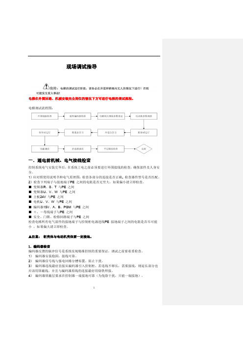
1现场调试指导电梯在外围回路、机械安装完全到位的情况下方可进行电梯的调试流程。
电梯调试流程图:一.通电前机械、电气接线检查控制系统电气安装完毕后,在系统上电之前必须要进行外围接线的检查,确保部件及人身安全。
1)应对照使用说明书和电气原理图,检查各部分的连接是否正确,2)检查下列端子与接地端子PE 之间的电阻是否无穷大,如果偏小请立即检查。
■ 变频器R 、S 、T 与PE 之间■ 变频器U 、V 、W 与PE 之间■ 主板24V 与PE 之间■ 电机U 、V 、W 与PE 之间■ 编码器15V 、A 、B 、PGM 与PE 之间■ +、-母线端子与PE 之间■ 安全、门锁、检修回路端子与PE 之间检查电梯所有电气部件的接地端子与控制柜电源进线PE 接地端子之间的电阻是否尽可能小 ,如果偏大请立即检查。
▲注意: 柜壳体与电动机壳体要一定接地。
1.编码器检查编码器反馈的脉冲信号是系统实现精准控制的重要保证,调试之前要着重检查。
1) 编码器安装稳固,接线可靠。
2) 编码器信号线与强电回路分槽布置,防止干扰。
3) 编码器连线最好直接从编码器引入控制柜,若连线不够长,需要接线,则延长部分也应该用屏蔽线,并且与编码器原线的连接最好用烙铁焊接。
4) 编码器屏蔽层要求在控制器一端接地可靠(为免除干扰,只能一端接地)。
5异步电机调谐流程图永磁同步电机调谐:1) 调谐说明a ) 永磁同步曳引机第一次运行前必须进行磁极位置辨识,否则不能正常使用。
b ) 同步机一体化控制器采用有传感器的闭环矢量控制方式,须确保F0-00 设为1(闭环矢量),且必须正确连接编码器和PG 卡,否则系统将报E20 编码器故障,导致电梯无法运行。
c ) 同步机一体化控制器既可通过操作面板控制方式在电机不带负载的情况下完成电机调谐,也可通过距离控制方式(检修方式)在电机带负载的情况下完成调谐。
d ) 调谐前必须正确设置编码器参数(F1-00、F1-12)和电机铭牌参数(F1-01、F1-02、F1-03F1-04、F1-05)。
达诺(Dorner)公司的3200、5200和5300系列顶部挂载90°驱动包的安装、维护和零件手册

For other service manuals visit our website at:/service_manuals.aspDORNER MFG. CORP .INSIDE THE USA OUTSIDE THE USAP .O. Box 20 • 975 Cottonwood Ave.TEL: 1-800-397-8664TEL: 262-367-7600Hartland, WI 53029-0020 USA FAX: 1-800-369-2440FAX: 262-367-5827851-530 Rev. G3200, 5200 & 5300 Series Top Mount 90° Drive Package for Standard Load GearmotorsInstallation, Maintenance & Parts ManualFeaturing:TechnologyDorner Mfg. Corp.2851-530 Rev. G3200, 5200 & 5300 Series Top Mount 90° Drive Package for Standard Load GearmotorsTable of ContentsIntroduction......................................................................... 2Warnings - General Safety.................................................. 3Product Description............................................................. 4Specifications...................................................................... 5Gearmotor Mounting Package Models:........................... 5Table 1: Gearmotor Specifications.................................. 5U.S. Version................................................................. 5CE Version................................................................... 5Table 2: Belt Speeds for Fixed Speed 90° Gearmotors... 6U.S. Version (60 Hz Gearmotors)................................ 6CE Version (50 Hz Gearmotors).................................. 6Table 3: Belt Speeds forVariable Speed 90° DC Gearmotors................................ 7U.S. Version................................................................. 7CE Version................................................................... 7Table 4: Belt Speeds forFixed Speed 90° VFD Gearmotors (7)Installation............................................................................ 8Required Tools................................................................. 8Mounting.......................................................................... 8Preventive Maintenance and Adjustment.......................... 11Required Tools............................................................... 11Timing Belt Tensioning.................................................. 11Timing Belt Replacement............................................... 11Drive or Driven Pulley Replacement............................. 12Gear Reducer Replacement............................................ 12Motor Replacement........................................................ 14Service Parts....................................................................... 16Top Mount Drive Package for90° Industrial Gearmotors............................................. 1690° Industrial Gearmotors.............................................. 18U.S. Version................................................................ 18CE Version.................................................................. 19Return Policy. (20)IntroductionUpon receipt of shipment:•Compare shipment with packing slip. Contact factory regarding discrepancies.•Inspect packages for shipping damage. Contact carrier regarding damage.•Accessories may be shipped loose. See accessory instruc-tions for installation.Dorner 3200 Series conveyors are covered by patentnumbers 5156260, 5156261, 5203447, 5265714 and patent applications in other countries.Dorner 3200 Series conveyors are covered by patentnumbers 5156260, 5156261, 5203447, 5265714, 6871737, 6910571, 6971509, and patent applications in other countries.Dorner LPZ Series conveyors are covered by patent numbers 5156260, 5156261, 5203447, 5265714, 5875883 and patent applications in other countries.Dorner 5200 Series conveyors have patents pending.Dorner reserves the right to make changes at any time without notice or obligation.Dorner has convenient, pre −configured kits of Key Service Parts for all conveyor products. These time saving kits are easy to order, designed for fast installation, and guarantee you will have what you need when you need it. Key Parts and Kits are marked in the Service Parts section of this manual with the Performance Parts Kits logo.IMPORTANTSome illustrations may show guards removed. DO NOT operate equipment without guards.851-530 Rev. G3Dorner Mfg. Corp.3200, 5200 & 5300 Series Top Mount 90° Drive Package for Standard Load GearmotorsWarnings - General SafetyA WARNINGThe safety alert symbol, black triangle with white exclamation, is used to alert you to potential personal injury hazards.Climbing, sitting, walking or riding on conveyor will cause severe injury.KEEP OFF CONVEYORS.DO NOT OPERATE CONVEYORS IN AN EXPLOSIVE ENVIRONMENT.A WARNINGExposed moving parts can cause severe injury.LOCK OUT POWER before removing guards or performing maintenance.A WARNINGGearmotors may be HOT.DO NOT TOUCH Gearmotors.A WARNINGExposed moving parts can cause severe injury.REPLACE ALL GUARDS BEFORE RUNNING CONVEYOR.A WARNINGDorner cannot control the physicalinstallation and application of conveyors. Taking protective measures is the responsibility of the user.When conveyors are used in conjunction with other equipment or as part of a multiple conveyor system, CHECK FOR POTENTIAL PINCH POINTS and other mechanical hazards before system start-up.Dorner Mfg. Corp.4851-530 Rev. G3200, 5200 & 5300 Series Top Mount 90° Drive Package for Standard Load GearmotorsProduct DescriptionRefer to (Figure 1) for typical components. Figure 1Mount Packages with Old Style Gearmotors prior toJune 2011Figure 2Mount Packages with e-Drive GearmotorsFigure 31Gearmotor 2Drive Pulley 3Timing Belt 4Driven Pulley 5Mounting Bracket 6Timing Belt Tensioner 7Conveyor 8Cover12346578NOTEThe 90° industrial gearhead changed configuration in 2011. See below for configuration details.851-530 Rev. G5Dorner Mfg. Corp.3200, 5200 & 5300 Series Top Mount 90° Drive Package for Standard Load GearmotorsSpecificationsGearmotor Mounting Package Models:Example:Table 1: Gearmotor SpecificationsU.S. VersionCE VersionItemStandard Load GearmotorSingle- Phase Three Phase VFD Variable Speed DC Variable SpeedOutput Power 0.5 hp (0.37 kw)Input Voltage 115VA C 208 – 230/460 VAC230 VAC 90VDC Input Frequency 60Hz 10 – 60Hz N/AInput Current (Amperes)7.4 2.1 – 2/1 1.6 5.0Gearmotor Ratios 5:1, 10:1, 20:1Frame Size NEMA 56CMotor TypeT otally enclosed, Fan cooledItemStandard Load GearmotorSingle Phase Three PhaseVFD VariableSpeedOutput Power 0.37 kWInput Voltage 230 VAC 230/400 VAC 230 VACInput Frequency 50 Hz 25 to 63 HzInput Current 2.6Amperes 2.1/1.2 Amperes 2.1AmperesGearmotor Ratios 5:1, 10:1, 20:1Protection Rating IP55Frame SizeIEC 71 B5Dorner Mfg. Corp.6851-530 Rev. G3200, 5200 & 5300 Series Top Mount 90° Drive Package for Standard Load GearmotorsSpecificationsTable 2: Belt Speeds for Fixed Speed 90° GearmotorsU.S. Version (60 Hz Gearmotors)(vp) = voltage and phase 11 = 115 V , 1-phase23 = 208 – 230/460 V , 3-phaseCE Version (50 Hz Gearmotors)(vp) = voltage and phase 21 = 230 V , 1-phase 23 = 230 V , 3-phase 43 = 400 V , 3-phaseLight Load GearmotorsStandard Load Gearmotors Belt Speed Drive Pulley Driven Pulley Part Number RPM In-lb N-m Part Number RPM In-lb N-m Ft/min M/min 32M060EL4(vp)FN 293193632M060ES4(vp)FN 2931936237.0161632M040EL4(vp)FN 4323826.932M040ES4(vp)FN 4337842.73410.4161632M040EL4(vp)FN 4323826.932M040ES4(vp)FN 4337842.75215.8241632M020EL4(vp)FN 861421632M020ES4(vp)FN 8628532.26921.0161632M020EL4(vp)FN 861421632M020ES4(vp)FN 8628532.210331.4241632M010EL4(vp)FN 173788.732M010ES4(vp)FN 17315317.313741.8161632M010EL4(vp)FN 173788.732M010ES4(vp)FN 17315317.317252.4201632M010EL4(vp)FN173788.732M010ES4(vp)FN 17315317.320662.82416N/A N/A N/A N/A 32M005ES4(vp)FN 34580927583.81616N/A N/A N/A N/A 32M005ES4(vp)FN 345809343104.52016N/AN/AN/AN/A32M005ES4(vp)FN345809412125.62416Light Load GearmotorsStandard Load GearmotorsBelt Speed M/minPart Number RPM N-m 1-phase/3-phasePart Number RPM N-m 1-phase/3-phase62Z060ES4(vp)FN 2336/3632Z060ES4(vp)FN 2336/36 5.862Z040ES4(vp)FN 3526.9/35.532Z040ES4(vp)FN 3526.9/35.58.562Z020ES4(vp)FN 7016/21.232Z020ES4(vp)FN 7032.2/32.217.162Z010ES4(vp)FN 14011.4/17.332Z010ES4(vp)FN 14017.3/17.333.862Z005ES4(vp)FN2804.5/5.932Z005ES4(vp)FN28017.3/17.368.0851-530 Rev. G7Dorner Mfg. Corp.3200, 5200 & 5300 Series Top Mount 90° Drive Package for Standard Load GearmotorsSpecificationsTable 3: Belt Speeds for Variable Speed 90° DC GearmotorsU.S. Version (60 Hz Gearmotors)CE Version (50 Hz Gearmotors)Table 4: Belt Speeds for Fixed Speed 90° VFD GearmotorsLight Load GearmotorsStandard Load Gearmotors Belt Speed Drive Pulley Driven Pulley Part Number RPM In-lb N-m Part Number RPM In-lb N-m Ft/min M/min 32M060ELD3DEN 4219822.432M060ESD9DEN 4219822.4 4.0 – 33 1.2 – 1016+9-32M040ELD3DEN 6316318.432M040ESD9DEN 6321524.3 6.0 – 50 1.8 – 15161632M040ELD3DEN 6316318.432M040ESD9DEN 6321524.39.0 – 75 2.7 – 23241632M020ELD3DEN 1259811.132M020ESD9DEN 12519622.112 – 100 3.6 – 30161632M020ELD3DEN 1259811.132M020ESD9DEN 12519622.118 – 150 5.5 – 45241632M010ELD3DEN 25054 6.132M010ESD9DEN 25010812.224 – 2007.3 – 61161632M010ELD3DEN 25054 6.132M010ESD9DEN 25010812.230 – 2509.1 – 76201632M010ELD3DEN250546.132M010ESD9DEN25010812.236 – 30011 – 922416Light Load Gearmotors Standard Load Gearmotors Belt Speed M/min Part Number RPM N-m Part Number RPM N-m 62Z060ES423EN 233632Z060ES423EN 2336 2.8 - 7.162Z040ES423EN 3535.532Z040ES423EN 3535.5 4.2 - 1162Z020ES423EN 7021.232Z020ES423EN 7032.28.5 - 2162Z010ES423EN 14017.332Z010ES423EN 14017.317 - 4362Z005ES423EN2805.932Z005ES423EN28017.334 - 86Standard Load GearmotorsBelt SpeedDrive Pulley Driven Pulley Part Number RPM In-lb N-m Ft/min M/min 32M060ES423EN 2931936 2.3 – 22.90.7 – 7.0161632M040ES423EN 4337842.7 3.4 – 34.3 1.0 – 10.5161632M040ES423EN 4337842.7 5.1 – 51.5 1.6 – 15.7241632M020ES423EN 8628532.2 6.9 – 68.6 2.1 – 20.9161632M020ES423EN 8628532.210.3 – 103.0 3.1 – 31.4241632M010ES423EN 17315317.313.7 – 137.3 4.2 – 41.9161632M010ES423EN 17315317.317.2 – 171.6 5.2 – 52.3201632M010ES423EN 17315317.320.6 – 205.9 6.3 – 62.8241632M005ES423EN 34580927.5 – 274.68.4 – 83.7161632M005ES423EN 34580934.3 – 343.210.5 – 104.6201632M005ES423EN34580941.2 – 411.912.6 – 125.62416NOTEFor belt speed other than those listed, contact factory for details.Dorner Mfg. Corp.8851-530 Rev. G3200, 5200 & 5300 Series Top Mount 90° Drive Package for Standard Load GearmotorsInstallationRequired Tools•Hex key wrenches:2 mm, 2.5 mm,3 mm, 5 mm •Straight edge •Torque wrenchMountingInstallation Component List:1.Typical components (Figure 4)Figure 4Figure 52.If required, change gearmotor position by removing four (4) screws (Figure 6,item 1). Rotate gearmotor to other position and replace screws. Tighten to 110 in-lb (12 Nm).Figure 6A WARNINGExposed moving parts can cause severe injury.LOCK OUT POWER before removing guards or performing maintenance.1Bottom Mount Assembly 2Drive Pulley 3Cover4M4 Socket Head Screws (4x)5Driven Pulley 6Output Shaft7Bearing Cover 8Spacer9Timing Belt145678923NOTEGearmotor may be operated in positions 1, 2 or 3 (Figure 5).11851-530 Rev. G9Dorner Mfg. Corp.3200, 5200 & 5300 Series Top Mount 90° Drive Package for Standard Load GearmotorsInstallation3.Locate drive output shaft (Figure 7,item 1). Remove two (2) M8 screws (Figure 7,item 2) and four (4) M6 screws (Figure 7,item 3) and discard.Figure 74.Apply anti-seize to motor shaft before assembling to gearbox. Attach mount assembly (Figure 8,item 1) with two (2) M8 screws (Figure 8,item 2) and four (4) M6 screws (Figure 8,item 3). Tighten M6 screws to 146 in −lbs (16.5 N −m) and M8 screws to 288 in −lbs (32.5 N −m).Figure 8 5.Install key (Figure 9,item 1).Figure 96.Wrap timing belt (Figure 9,item 2) around driven pulley (Figure 9,item 3) and drive pulley (Figure 9,item 4). Install driven pulley onto conveyor shaft.7.Using a straight edge (Figure 10,item 1), align driven pulley (Figure 10,item 2) with drive pulley (Figure 10,item 3).Figure 10A WARNINGDrive shaft keyway may be sharp.HANDLE WITH CARE.31231234231312Dorner Mfg. Corp.10851-530 Rev. G3200, 5200 & 5300 Series Top Mount 90° Drive Package for Standard Load GearmotorsInstallation8.Tighten driven pulley taper-lock screws (Figure 11,item 1).Figure 119.Depending on conveyor belt travel (direction A or B), locate timing belt tensioner (Figure 12,item 1) as shown. Tension timing belt to obtain 1/8” (3 mm) deflection for 6 lb (3 Kg) of force at timing belt mid-point (Figure 12,item 2). Tighten tensioner screw to 110 in-lb (12 Nm).Figure 1210.Install cover (Figure 13,item 1) with four (4) screws(Figure 13,item 2). Tighten screws to 35 in-lb (4 Nm).Figure 13121BA122851-530 Rev. G11Dorner Mfg. Corp.3200, 5200 & 5300 Series Top Mount 90° Drive Package for Standard Load GearmotorsPreventive Maintenance and AdjustmentRequired Tools•Hex key wrenches: 2 mm, 2.5 mm, 3 mm, 5 mm •Adjustable wrench (for hexagon head screws)•Straight edge •Torque wrenchTiming Belt Tensioning1.Remove four (4) screws(Figure 13,item 2) and remove cover (Figure 13,item 1).2.Loosen tensioner (Figure 14,item 1).Figure 143.Depending on conveyor belt travel (direction A or B), locate timing belt tensioner (Figure 12,item 1) as shown. Tension timing belt to obtain 1/8” (3 mm) deflection for 6 lb (3 Kg) of force at timing belt mid-point (Figure 12,item 2). Tighten tensioner screw to 110 in-lb (12 Nm).4.Install cover (Figure 13,item 1) with four (4) screws (Figure 13,item 2). Tighten screws to 35 in-lb (4 Nm).Timing Belt Replacement1.Remove four (4) screws(Figure 13,item 2) and remove cover (Figure 13,item 1).2.Loosen tensioner (Figure 14,item 1).3.Remove timing belt (Figure 15,item 1).Figure 154.Install new timing belt.5.Depending on conveyor belt travel (direction A or B), locate timing belt tensioner (Figure 12,item 1) as shown. Tension timing belt to obtain 1/8” (3 mm) deflection for 6 lb (3 Kg) of force at timing belt mid-point (Figure 12,item 2). Tighten tensioner screw to 110 in-lb (12 Nm).6.Install cover (Figure 13,item 1) with four (4) screws (Figure 13,item 2). Tighten screws to 35 in-lb (4 Nm).A WARNINGExposed moving parts can cause severe injury.LOCK OUT POWER before removing guards or performing maintenance.1A WARNINGExposed moving parts can cause severe injury.LOCK OUT POWER before removing guards or performing maintenance.NOTEIf timing belt does not slide over pulley flange, loosen driven pulley taper-lock screws (Figure 15,item 2) and remove pulley with belt (Figure 15,item 1). For re-installation, see steps 6 through 8 on page 9.12Dorner Mfg. Corp.12851-530 Rev. G3200, 5200 & 5300 Series Top Mount 90° Drive Package for Standard Load GearmotorsPreventive Maintenance and AdjustmentDrive or Driven Pulley Replacementplete steps 1 through 3 of “Timing BeltReplacement” section on page 11.2.Remove taper-lock screws (Figure 16,item 1). Insert one (1) of taper lock screws in remaining hole (Figure 16,item 2). Tighten screw until pulley is loose. Remove pulley and taper hub assembly.Figure 163.Complete steps 6 through 10 of “Installation” section starting on page 9.Gear Reducer Replacement1.Remove four (4) screws(Figure 13,item 2) and remove cover (Figure 13,item 1).2.Loosen tensioner (Figure 14,item 1).3.Loosen taper-lock screws (Figure 17,item 1) andremove drive pulley: Insert one (1) of taper lock screws in remaining hole (Figure 17,item 2). Tighten screw until pulley is loose.Figure 174.Remove drive pulley (Figure 18,item 1), taper hub assembly (Figure 18,item 2), and timing belt (Figure 18,item 3).Figure 18A WARNINGExposed moving parts can cause severe injury.LOCK OUT POWER before removing guards or performing maintenance.NOTEIf drive pulley (Figure 18,item 1) is replaced, wrap timing belt around drive pulley and complete step 3.12A WARNINGExposed moving parts can cause severe injury.LOCK OUT POWER before removing guards or performing maintenance.21321851-530 Rev. G13Dorner Mfg. Corp.3200, 5200 & 5300 Series Top Mount 90° Drive Package for Standard Load GearmotorsPreventive Maintenance and Adjustment5.Remove four (4) gear reducer mounting screws (Figure 19,item 1). Remove gearmotor.Figure 196.Remove four screws (Figure 20,item 1). Detach motor (Figure 20,item 2) from gear reducer (Figure 20,item 3). Retain shaft key (Figure 20,item 4).Figure 207.Remove two (2) screws (Figure 21,item 1) and detach output shaft cover (Figure 21,item 2).Figure 218.Hold the driveshaft with a wrench (Figure 22,item 1) as shown to keep shaft from turning, while removing screw (Figure 22,item 2) with hex wrench (Figure 22,item 3).Figure 229.Remove driveshaft (Figure 23,item 1) and key (Figure 23,item 2).Figure 2310.Replace gear reducer (Figure 23,item 3).11.Apply anti-seize (Figure 24,item 1) to shaft.Figure 2411142321NOTEOutput shaft (Figure 22,item 1) is held in Gear Reducer with a tapered press fit.Removal may require use of an arbor press.1321231Dorner Mfg. Corp.14851-530 Rev. G3200, 5200 & 5300 Series Top Mount 90° Drive Package for Standard Load GearmotorsPreventive Maintenance and Adjustment12.Replace the original shaft components into new gearreducer (Figure 23).13.Apply anti-seize to motor shaft before assembling togearbox. With key (Figure 20,item 4) in keyway, slide motor (Figure 20,item 2) and gear reducer (Figure 20,item 3) together. Install screws (Figure 20,item 1) and tighten.14.Hold the driveshaft with a wrench (Figure 22,item 1)as shown to keep shaft from turning, while installing screw (Figure 22,item 2) with hex wrench (Figure 22,item 3). Tighten screw to 350 in-lb (39.5 Nm).15.Install gearmotor to mounting bracket and tightenscrews (Figure 19,item 1) to 110 in-lb (12 Nm).plete steps 6 through 10 of “Installation” sectionstarting on page 9.Motor Replacement1.For single phase motor, unplug power cord from outlet.2.For three phase and VFD variable speed motor: a.Loosen terminal box screws (Figure 25,item 1) and remove cover (Figure 25,item 2).Figure 25b.Record wire colors on terminals 1, 2 and 3. Loosen wire nuts and remove wires 1, 2 and 3.c.Loosen cord grip and remove cord.IMPORTANTBe extremely careful when coupling motor to gear reducer. Avoid misalignment and forcing the connection causing possible permanent gear reducer seal damage.NOTEDrive pulley (Figure 18,item 1) is removed. Wrap timing belt around drive pulley and complete step 15.A WARNINGExposed moving parts can cause severe injury.LOCK OUT POWER before removing guards or performing maintenance.Hazardous voltage will cause severe injury or death.LOCK OUT POWER BEFORE WIRING.211851-530 Rev. G15Dorner Mfg. Corp.3200, 5200 & 5300 Series Top Mount 90° Drive Package for Standard Load GearmotorsPreventive Maintenance and Adjustment3.For DC variable speed motor, unplug motor cord at disconnect (Figure 26,item 1).Figure 264.Remove four (4) screws (Figure 27,item 1). Detach motor (Figure 27,item 2) from gear reducer (Figure 27,item 3). Retain motor output shaft key (Figure 27,item 4).Figure 275.Apply anti-seize to motor shaft before assembling to gearbox. With key (Figure 28,item 1) in keyway, slide motor (Figure 28,item 2) and gear reducer together. Install screws (Figure 28,item 3) and tighten.Figure 286.Replace wiring:•For a single phase motor, reverse step 1 on page 14.•For a three phase or VFD variable speed motor, reverse step 2 on page 14.•For a DC variable speed motor, reverse step 3 on page 15.IMPORTANTBe extremely careful when coupling motor to gear reducer. Avoid misalignment and forcing the connection causing possible permanent gear reducer seal damage.12143213Dorner Mfg. Corp.16851-530 Rev. G3200, 5200 & 5300 Series Top Mount 90° Drive Package for Standard Load GearmotorsService PartsTop Mount Drive Package for 90° Industrial GearmotorsNOTEFor replacement parts other than those shown in this section, contact an authorized Dorner Service Centeror the factory. Key Service Parts and Kits are identified by the Performance Parts Kits logo . Dorner recommends keeping these parts on hand.851-530 Rev. G17Dorner Mfg. Corp.3200, 5200 & 5300 Series Top Mount 90° Drive Package for Standard Load GearmotorsService PartsItem Part NumberDescription 1300871Drive Cover 2301076Drive T ensioner Slide 3301153Tensioner Bearing Assembly 4350115Adapter Ring 5350117Drive Shaft (for E-Drive 56 C FaceGearmotors)350133Drive Shaft (for E-Drive IEC 63B5 andIEC 71B5 Gearmotors)6350123Mounting Plate 7807-2016Drive-Bearing Shaft Cover 8911-013Flat Washer 9912-084Square Key, 0.188" x 1.50"(for E-Drive 56 C Face Gearmotors)980636M Square Key, 6 mm x 36 mm(for E-Drive IEC 63B5 and IEC 71B5 Gearmotors)10814-125Timing Belt, 1.0" W x 25.5" L814-059Timing Belt, 1.0" W x 27.0" L 814-060Timing Belt, 1.0" W x 28.0" L 814-079Timing Belt, 1.0" W x 30.0" L11811-133Driven Pulley, 14 Tooth,Taper Lock TL1108811-126Driven Pulley, 16 Tooth,Taper Lock TL110812811-133Drive Pulley, 14 Tooth,Taper Lock TL1108811-126Drive Pulley, 16 Tooth,Taper Lock TL1108811-127Drive Pulley, 18 Tooth,Taper Lock TL1210811-135Drive Pulley, 20 Tooth,Taper Lock TL1210811-136Drive Pulley, 22 Tooth,Taper Lock TL1610811-137Drive Pulley, 24 Tooth,Taper Lock TL161013811-288Taper Lock Bushing, 20 mm, TL1108811-289Taper Lock Bushing, 20 mm, TL1210811-290Taper Lock Bushing, 20 mm, TL161014920483M Flanged Socket Head Screw,M4 x 16 mm15920608M Socket Head Screw, M6-1.00 x 8 mm 16920612M Socket Head Screw,M6-1.00 x 12 mm17920620M Socket Head Screw,M6-1.00 x 20 mm18920835M Socket Head Screw,M8-1.25 x 35 mm19931018M Flat Screw, M10 - .50 x 18 mm 20961645M Hex Head Cap Screw,M16 - 2.00 x 45 mm21980018M Square Key, 6 mm x 18 mm 22980632M Square Key, 6 mm x 32 mm 23991610M Hex NutDorner Mfg. Corp.18851-530 Rev. G3200, 5200 & 5300 Series Top Mount 90° Drive Package for Standard Load GearmotorsService Parts90° Industrial GearmotorsU.S. Version12Item Part No.Description162MES411FN Motor, 0.25hp (0.19Kw), 115/230 Volts,60 Hz, 1-Phase62MES423FN Motor, 0.25hp (0.19Kw), 208−230/460 Volts, 60 Hz, 3-Phase22MSD3DEN Motor, 0.25hp (0.19Kw), 130 VDC 62MEH411FN Motor, 0.5hp (0.37Kw), 115/230 Volts, 60Hz, 1−Phase32MEH423FN Motor, 0.5hp (0.37Kw) 208−230/460 Volts, 60Hz, 3 Phase62MHD9DEN Motor, 0.5hp (0.37Kw), 90 VDC 32MES423ENMotor, 0.5hp (0.37Kw), 230 Volts, 3 Phase Inverter Duty32MHD9DENMotor, 0.75 hp, (0.56Kw), 90 VDC 2 32M005EL Gear Reducer, 5:1, NEMA 42CZ 32M010EL Gear Reducer, 10:1, NEMA 42CZ 32M020EL Gear Reducer, 20:1, NEMA 42CZ 32M040EL Gear Reducer, 40:1, NEMA 42CZ 32M060EL Gear Reducer, 60:1, NEMA 42CZ 32M005ES Gear Reducer, 5:1, NEMA 56C 32M010ES Gear Reducer, 10:1, NEMA 56C 32M020ES Gear Reducer, 20:1, NEMA 56C 32M040ES Gear Reducer, 40:1, NEMA 56C 32M060ES Gear Reducer, 60:1, NEMA 56C 32M010EHGear Reducer, 10:1, NEMA 140 TC851-530 Rev. G19Dorner Mfg. Corp.3200, 5200 & 5300 Series Top Mount 90° Drive Package for Standard Load GearmotorsService PartsCE Version12Item Part No.Description1826-281Motor, 0.19 kW 230 Volts, 1400 RPM50 Hz, 1-Phase826-282Motor, 0.37 kW 230 Volts, 1400 RPM 50 Hz, 1-Phase826-284Motor, 0.19 kW 230/400 Volts, 1400 RPM 50 Hz, 3-Phase826-285Motor, 0.37 kW 230/400 Volts, 1400 RPM 50 Hz, 3-Phase262Z005ES Gear Reducer, 5:1, 63 B562Z010ES Gear Reducer, 10:1, 63 B562Z020ES Gear Reducer, 20:1, 63 B562Z040ES Gear Reducer, 40:1, 63 B562Z060ES Gear Reducer, 60:1, 63 B532Z005ES Gear Reducer, 5:1, 71 B532Z010ES Gear Reducer, 10:1, 71 B532Z020ESGear Reducer, 20:1, 71 B5851-530 Rev. G Printed in U.S.A.Dorner Mfg. Corp. reserves the right to change or discontinue products without notice. All products and services are covered inaccordance with our standard warranty. All rights reserved. © Dorner Mfg. Corp. 2011DORNER MFG. CORP .975 Cottonwood Ave., PO Box 20 Hartland, WI 53029-0020 USA TEL 1-800-397-8664 (USA)FAX 1-800-369-2440 (USA)Internet: Outside the USA:TEL 1-262-367-7600FAX 1-262-367-5827Return PolicyReturns must have prior written factory authorization or they will not be accepted. Items that are returned to Dorner without authorization will not be credited nor returned to the original sender. When calling for authorization, please have the following information ready for the Dorner factory representative or your local distributor: and address of customer.2.Dorner part number(s) of item(s) being returned.3.Reason for return.4.Customer's original order number used when ordering the item(s).5.Dorner or distributor invoice number (if available, part serial number).A representative will discuss action to be taken on the returned items and provide a Returned Goods Authorization (RMA) number for reference. RMA will automatically close 30 days after being issued. To get credit, items must be new andundamaged. There will be a return charge on all items returned for credit, where Dorner was not at fault. It is the customer’s responsibility to prevent damage during return shipping. Damaged or modified items will not be accepted. The customer is responsible for return freight.Returns will not be accepted after 60 days from original invoice date. The return charge covers inspection, cleaning,disassembly, disposal and reissuing of components to inventory. If a replacement is needed prior to evaluation of returned item, a purchase order must be issued. Credit (if any) is issued only after return and evaluation is complete.Dorner has representatives throughout the world. Contact Dorner for the name of your local representative. Our Customer Service Team will gladly help with your questions on Dorner products.For a copy of Dorner's Warranty, contact factory, distributor, service center or visit our website at .For replacement parts, contact an authorized Dorner Service Center or the factory.Product TypeStandard ProductsEngineered to order partsProduct LineConveyors Gearmotors & Mounting Packages Support Stands Accessories Spare Parts (non-belt)Spare Belts - Standard Flat Fabric Spare Belts - Cleated & Specialty FabricSpare Belts -Plastic Chain All equipment and parts110030% return fee for all products except:50% return fee for conveyors with modular belt,cleated belt or specialty beltsnon-returnablecase-by-case22002200 Modular Belt 2200 Precision Move 23002300 Modular Belt 32003200 LPZ3200 Precision Move 4100520053006200Controls 7200 / 730050% return fee for all products7350non-returnable736074007600。
- 1、下载文档前请自行甄别文档内容的完整性,平台不提供额外的编辑、内容补充、找答案等附加服务。
- 2、"仅部分预览"的文档,不可在线预览部分如存在完整性等问题,可反馈申请退款(可完整预览的文档不适用该条件!)。
- 3、如文档侵犯您的权益,请联系客服反馈,我们会尽快为您处理(人工客服工作时间:9:00-18:30)。
UNO-3000G系列模式跳线
研华IAG FAE
吴峥
2014-03
UNO-3000G系列串口工作模式和开机启动模式选择可以通过BIOS设置,也可以通过硬件跳线模式来选择,建议用硬件跳线模式,这样更稳定。
以下跳线设置适用于UNO-3073G、3075G、3083G、3085G系列。
开机启动模式
默认是ATX模式,需要按开机按钮开机,将JP3(在CFast插槽上方)跳到1-2位置,可切换到AT 模式,上电主机即可启动。
串口工作模式
BIOS配置串口工作模式相当于软件方式,经过测试,串口工作模式以跳线设置的模式为优先,如果BIOS内设置的模式和跳线设置的模式不同,在上电时,串口工作模式有一个切换的过程。
所以,建议使用硬件(跳线)方式更稳定。
以下是使用硬件(跳线)方式的步骤:
1.进入BIOS,切换到Advanced页,进入“NCT6776F Super IO Configuration”
2.选择“Serial Port 1 Configuration”串口1或“Serial Port 2 Configuration”串口2,进
入配置,改“Serial port Mode Controlled by”设置为“Switch”,保存BIOS并退出。
3.断电后,改变主板上SW1、SW4的跳线,即可设定为相应的串口模式(SW1、SW4位置在电池旁边)。
(默认SW1、SW4的1-4都为OFF,即RS-485/422模式)。