EKC331T使用手册
开利压缩机及压缩机组产品介绍

Carrier 压缩机及并联机组张廷勋 Company Private主要讨论内容1. 开利压缩机介绍2. 开利并联机组以及介绍3. 开利机组控制系统 4. 开利工业和商业用最新冷冻产品1开利压缩机产品系列半封螺杆压缩机 开启式双螺杆压缩机 4 缸 06D半封活塞 6 缸 06D半封活塞涡旋压缩机 6 缸 06E 半封活塞滚动转子压缩机开启式活塞压缩机 5H60 2开利压缩机冷冻制冷压缩机系列06DM/R 单级压缩机 2 ~ 10HP -40 ~ 7ºC 06EM/R 单级压缩机 15~ 35HP -40 ~ 7ºCCO2 & R410A 正在研发中!R22, R404A可以适 用于所有的Carrier 制冷压缩机。
06CC 双级低温压缩机 2 ~ 30HP -50~ -23ºC3开利压缩机目前中国可以选用的压缩机06CC Low temp Two Stage 15 ~ 30HP -50~ -23ºC 06ER Single Stage Low Temp 15 ~ 30HP -40 ~ -18ºC 06D/EM Single Stage Med Temp 15 ~ 35HP -18 ~ 7ºCCarlyle Compressor Manufactured in ChinaSingle stage low temperature-06ER Model 06ER450 06ER465 06ER475 06ER399 Motor HP 15 20 20 30 06EM475 06EM499 25 35 Single stage Medium Temperature-06EM Model 06EM450 Motor HP 15 Two stage Compressor-O6CC Model 06CC550 06CC665 06CC675 06CC899 Motor HP 15 20 20 3006DR316 06DR228 06DR337 and 06CC316 06CC228 06CC337 (5HP 7.5HP 10HP) are doing the localization in China.4市场情况目前在美国超市冷冻系统每年对活塞式制冷压缩机的需求是大约每年 55,000台,开利以35%的市场份额在市场占主导地位。
3311电子负载使用说明书
4.1 本地电压检知连接法 ......................................................................................................... 29 4.2 远地电压检知连接法 ......................................................................................................... 30 4.3 固定电流模式 (C.C. MODE)的应用................................................................................. 31 4.4 固定电阻模式(C.R. MODE)的应用................................................................................... 33 4.5 固定电压模式 (C.V. MODE)的应用................................................................................. 34 4.6 固定功率模式(C.P. MODE)的应用 ................................................................................... 35 4.7 多组输出之电源供应器与电子负载之连接 ................................................................ 36 4.8 并联操作................................................................................................................................. 37
HI331蓝牙HART接口用户手册说明书
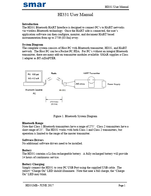
HI331 User ManualIntroductionThe HI331 Bluetooth HART Interface is designed to connect PC’s to HART networks via wireless Bluetooth technology. Once the HART side is connected, the user’s application software can then configure, monitor, and document HART based instrumentation from up to 275ft (83.8m) away.System DiagramThe complete system consists of Host PC with Bluetooth transmitter, HI331, and HART network. The Host PC can be a Pocket PC PDA. For PC’s without an integral Bluetooth transmitter, there are many add-on transmitter modules available. SMAR supplies a Class 1 adapter as BT-ADAPTER.Figure 1. Bluetooth System DiagramBluetooth RangeNote that Class 1 Bluetooth transmitters have a range of 275’. Class 2 transmitters have a short r ange of 25’. The HI331 works with both Class 1 and Class 2 transmitters, but operation is limited to the range of the master transmitter.Software DriversNo additional software drivers need to be installed.BatteryThe HI331 contains a Li-Ion rechargeable battery. A fully recharged battery will provide 14 hours of continuous service.Battery ChargingSimply connect the HI331 to your PC USB Port using the supplied USB cable. The yellow “Charge On” LED should illuminate. Note that near a full charge, the “Charge On” LED may blink.Power Switch and LEDPress the power switch to turn on the unit. The green “Power” LED will illuminate when the unit is on. Press the power switch again to turn the unit off. Turn the unit off when not in use to conserve battery life.Battery Charge ErrorWhen the red “Charge Error” LED illuminates, there is a battery charge error condition. This is most likely due to high temperature on the battery. Remove the USB cable from the unit and turn the unit off. Put the unit in a cool location and wait 30 minutes before attempting a recharge. Contact SMAR if the condition persists.Initial PC Setup/ Bluetooth Modem DiscoveryThe following procedure must be done at least once for the PC to “Discover” the HI331.1.Turn on the HI331. It does not need to be connected to the HART network.2.Run the Bluetooth driver software that came with your PC or Bluetooth adapter(ie Linksys). There is typically a Bluetooth icon on the system tray that can bedouble clicked.3.Select “Find Bluetooth Devices” or “Site Survey” to locate any Bluetooth devicesin the area. You could also search for services. Search for “Serial Services” toalso locate Bluetooth devices.4. A device labeled “HART Modem” should be discovered.5.Double click on the “HART Modem” icon. The available serial service willappear as “AMP-SPP”, and say it is not connected.6.Double click on “AMP-SPP”. The Bluetooth connection will be made and theassigned COM port will be reported. Note that if 2 COM ports are reported, usethe “Outgoing” port. Note this port number for your application software.7.Some Bluetooth drivers may prompt for a “Passcode”. Enter “1234”, without thequotes.Discovery needs to be repeated only when adding or changing HI331 modems, or when multiple modems are in the Bluetooth area.Good Practices for PC ApplicationsWe recommend the following steps before use HI331:Install SMAR AssetView StandAlone-Install Smar AssetView StandAlone (or third part Software based on FDT/DTM) that are available in the package;Install DTM for HI331 and Smar Device Library (HART)-Run Setup from HI331 CD/DVD Install (this step will install DTM’s for HI331 and Smar HART Device Library);-After these 2 steps, run Smar AssetView for the first time. Go to the Update Catalogue before start using HI331;PC ApplicationsStart your PC application and set the com port setting to use the com port reported during Discovery. Use the application as normal. The HI331 looks like a normal RS232 device to the application software. The application software does not need to be modified.Multiple HI331 ModemsWhen several modems are in the same area, the Discovery process needs to be repeated. The modems will appear as “HART Modem (1)”, “HART Modem (2)”, etc. It may require trial and error to determine which modem is connected to the desired HART network.HART ConnectionsThe modem can be connected in one of two ways: across the loop load resistor (A – B) or across the HART transmitter terminals (C – D). See Figure 2.Figure 2. HART ConnectionsNOTE: Make the HART connections before turning on the power to the modem. This will improve initial communication reliability.PC Test SoftwareProgram “HM Test” is included on the installation CD to test the operation of the HI331. Launch the program from the CD or from the installed icon. Enter the com port that was assigned to the modem by Windows. Then select “Poll HART Network” to connect to a HART device. The program sends HART Command 0 to determine what transmitters are connected to the loop. The “Status” box will indicate successful operation of theHI331 in your sys tem. Consult the “Troubleshooting” section of this manual if test failure.TroubleshootingProblem:Will not communicateVerify the following:1. Com port number in application is the HI331 com port number.2. Loop power supply is on.3. Loop resistance between 250 ohms and 1Kohms.4. Loop current within HART limits.5. If multi drop configuration, all transmitters in loop have unique addresses.6. HI331 HART connections across loop resistor or across transmitter terminals.7. Battery is charged.8. Modem power switch is on and LED is illuminated.9. Perform the “Discovery” procedure again and verify a connection can be made.10. If using the Linksys USBBT100, verify the Linksys Bluetooth driver is installed and not the Windows Bluetooth driver. There is a known issue with the Linksys install and Windows XP SP2. Go to and search for “USBBT100” for details. Problem:Communications unreliableVerify the following:1. You are in radio range of the master transmitter. For Class 1 devices 275 ft, for Class2 devices, 25 ft.2. Vary the orientation of the master transmitter or the HI331 to improve radio link strength.3. Battery is charged.4. HART connections made before power turned on.5. Transmitter not in Burst mode. Communications can occur in Burst mode, but more retries will be necessary for success.6. In some applications, a connection can be lost, which looks like a communication lock-up. Perform the Discovery process again to reestablish the link without the need to restart your application.Problem:Will not communicate with CornerstonePerform the following:1. In directory “CSCONFIG/DB”, open file “CSLOCAL.INI”.2. Search for “[RDLS2]” without the quotes.3. Change “Debug=0” to “Debug=8”, again without the quotes.4. Save the file.Notice of FCC ComplianceThis product contains a radio module that has been tested and found to comply with the FCC Part15 Rules. These limits are designed to provide reasonable protection against harmful interference in approved installations. This equipment generates, uses, and can radiate radio frequency energy and, if not installed and used in accordance the instructions, may cause harmful interference to radio communications.However, there is no guarantee that interference will not occur in a particular installation. This device complies with part 15 of the FCC Rules. Operation is subject to the following two conditions: (1) This device may not cause harmful interference, and (2) this device must accept any interference received, including interference that may cause undesired operation. Modifications or changes to this equipment not expressly approved by SMAR Ltd may void t he user’s authority to operate this equipment.Contains Transmitter Module FCC ID: X3ZBTMOD1。
克雷尔一智能家居安防系统操作指南说明书
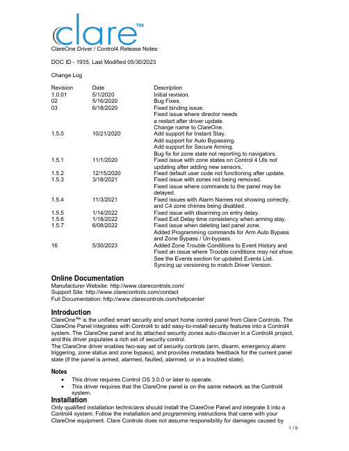
ClareOne Driver / Control4 Release NotesDOC ID - 1935, Last Modified 05/30/2023Change LogRevision Date Description1.0.01 5/1/2020 Initial revision.02 5/16/2020 Bug Fixes.03 6/18/2020 Fixed binding issue.Fixed issue where director needsa restart after driver update.Change name to ClareOne.1.5.0 10/21/2020 Add support for Instant Stay.Add support for Auto Bypassing.Add support for Secure Arming.Bug fix for zone state not reporting to navigators.1.5.1 11/1/2020 Fixed issue with zone states on Control 4 UIs notupdating after adding new sensors.1.5.2 12/15/2020 Fixed default user code not functioning after update. 1.5.3 3/18/2021 Fixed issue with zones not being removed.Fixed issue where commands to the panel may bedelayed.1.5.4 11/3/2021 Fixed issues with Alarm Names not showing correctly,and C4 zone chimes being disabled.1.5.5 1/14/2022 Fixed issue with disarming on entry delay.1.5.6 1/18/2022 Fixed Exit Delay time consistency when arming stay. 1.5.7 6/08/2022 Fixed issue when deleting last panel zone.Added Programming commands for Arm Auto Bypassand Zone Bypass / Un-bypass.16 5/30/2023 Added Zone Trouble Conditions to Event History andFixed an issue where Trouble conditions may not show.See the Events section for updated Events List.Syncing up versioning to match Driver Version. Online DocumentationManufacturer Website: /Support Site: /contactFull Documentation: /helpcenterIntroductionClareOne™ is the unified smart security and smart home control panel from Clare Controls. The ClareOne Panel integrates with Control4 to add easy-to-install security features into a Control4 system. The ClareOne panel and its attached security zones auto-discover in a Control4 project, and this driver populates a rich set of security control.The ClareOne driver enables two-way set of security controls (arm, disarm, emergency alarm triggering, zone status and zone bypass), and provides metadata feedback for the current panel state (if the panel is armed, alarmed, faulted, alarmed, or in a troubled state).Notes•This driver requires Control OS 3.0.0 or later to operate.•This driver requires that the ClareOne panel is on the same network as the Control4 system.InstallationOnly qualified installation technicians should install the ClareOne Panel and integrate it into a Control4 system. Follow the installation and programming instructions that came with your ClareOne equipment. Clare Controls does not assume responsibility for damages caused byimproper installation, connection the network, or use of the device.SDDP SetupInstall, configure, and test the ClareOne panel and all connected sensors. The ClareOne driver supports communication within the Control4 system over Wi-Fi and ethernet connection types. Verify that the ClareOne panel is fully functional and configured before integrating with Control4.The ClareOne panel and system needs to be activated through the Clare back-end management platform, FusionPro™, to have security monitoring services enabled. All Control4 integrators authorized to sell ClareOne have been set up with FusionPro accounts. For full ClareOne panel installation and configuration, see ClareOne Wireless Security and Smart Home Panel User Manual (DOC ID 1871).To add the driver (SDDP):Access Composer and browse to the Discovered tab.Composer > System Design > Discovered.Sort the list of discovered SDDP devices by Manufacturer.The ClareOne panel is listed with:Type: SecurityManufacturer: Clare ControlsModel: CLR-C1-PNLAddress field: clarecontrols:security-clarehome-MAC ADDRESSNote: The MAC address uses all capital letters.Double-click on the discovered ClareOne Panel to add it and its attached sensors to the project. When the panel is added this way, it automatically configures itself.That’s it, you are done with setup.Proceed to testing the integration and custom programming.Supported FeaturesOnce the ClareOne panel is added to the project in Composer, the Control4 user interface displays ClareOne as the security subsystem and allows the Control4 system to control the ClareOne panel. The available Control4 security commands enabled by the ClareOne driver are listed below.Arm Stay: Allows Control4 to arm the ClareOne panel in Arm Stay mode. When the ClareOne panel is armed to Stay any zone configured as Active in Stay in the ClareOne Sensor Management Settings with be armed.Arm Away: Allows Control4 to arm the ClareOne panel in Arm Away mode. When the ClareOne panel is armed to Away any zone configured as Active in Away in the ClareOne Sensor Management Settings with be armed.Note: When arming to Away without opening a zone, the ClareOne panel will arm in Stay mode. This is called Auto Armed Stay. This option can be disabled on the ClareOne panel under User Settings > Security & Arming > Auto Armed StayInstant Stay: Allows Control4 to arm the ClareOne panel to Armed Stay mode Instantly with no delay.Note: When using this option there is no entry delay. If an entry zone is tripped, the ClareOne will enter an intrusion alarm condition.Secure Arming: Allows the ClareOne panel to require a user PIN code when arming the system. Secure Arming is disabled by default and can be enabled by navigating to Settings > User Settings > Security & Arming. When Secure Arming is enabled the Control4 system prompts the user for a PIN code.Note: Regardless of the Secure Arming state (enabled/disabled), the user is always prompted for a PIN when arming the system with open zones (Auto Zone Bypass).Disarm: Allows Control4 to disarm the ClareOne panel.Remote Arming / Disarming Support– With an active 4sight subscription, users can access their ClareOne system remotely. The ClareOne panel supports remote arming and disarming through Control4. The integrator has the option to disable remote disarming in Composer Pro. Security Sensor States: Sensor states can be used for Automation Events in Control4Zone Status: Supports real-time zone status updates, even when the ClareOne panel is Disarmed. Zones and their names are automatically imported and show real-time status in Control4. Automations can be built inside Control4 triggered by ClareOne events.Note: The active in arm states of non-Environmental ClareOne sensors can be set for Away and Stay individually. When a sensor is ignored in a particular arm state the sensor will still report its status in real-time but will not trigger an alarm event. This setting can be accessed from the ClareOne panel by selecting User Settings > Sensor Management then select the pencil icon next to a particular sensor. The Control4 integrator can take advantage of this feature with custom programming to trigger activities.Auto Zone Bypass: Allows Control4 to prompt the user with all open zones and allows for auto bypassing with confirmation from the user.Note: The user’s PIN will be required when auto bypassing sensors, whether Secure Arming is enabled or disabled.Emergency: Allows Control4 to set an Emergency condition on the ClareOne panel. Warning: The Control4 user could trigger a Panic or an Emergency condition remotely. The alarm call center will act and respond the same as if trigger locally.Fire: Alerts the central station to a fire panic.Panic: Alerts the central station that police are needed.Police: Calls the monitored alarm station and allows for two-way voice communication(two-way communication is not available for silent panic).Auxiliary (Medical): Calls the monitored alarm station and allows for two-way voicecommunication (two-way communication is not available for silent panic).Trouble Conditions: Allows Control4 to display the ClareOne panel’s trouble conditions.•Panel tamper: The panel’s tamper has been activated.•Missing battery: There is no battery detected/installed.•Panel low battery: The panel’s battery charge is low.•Panel on battery: The only panel power is provided by the battery.•Supervisory trouble: The panel lost connection to the central station.•Ethernet trouble: Ethernet or Wi-Fi connection is lost.•Auto configuration and zone importing: All zones are automatically added with their set names. New zones are added when the ClareOne panel is updated.Note: A dealer may need to refresh the Control4 Navigator when new zones are added.Zones / Users: The ClareOne Panel supports up to 128 sensor zones and 99 users. The ClareOne Duress user pin code cannot be used to disarm the panel through Control4.Entry / Exit Delay Countdown: The number of seconds remaining in the exit or entry process. The countdown timer will be shown in the Control4 apps and on T3/T4 Series Touch Screens. SDDP: Supports SDDP discovery over Wi-Fi or Ethernet connections.Supported Features using theT3/T4 Series Touch ScreenWhen using a T3/T4 Series Touch Screen the ClareOne panel(s) must be enabled to show on each touch screen device individually. Navigate to the Security Partition device in Composer Pro and click on the “Set UI Associations” button. Select Show Panel, Entr y/Exit Chime, and PanelChime to take advantage of all ClareOne features below.The following feature are supported by the ClareOne panel when using T3/T4 Series Touch Screens:Chime on Entry Delay and Exit DelayTo enable the delay chimes on your T3/T4 touch screen tap on your security paneldevice, then Settings, and select “Chime on entry/exit delay”Chime on Zone OpenTo enable the Chime on Zone Open for a certain zone, in Composer Pro navigate to the Security Panel Zone Properties, double click on a zone, select the Chimes box, selectSave, and refresh the Navigators.Emergency TriggeringEmergency Alarms can be triggered from the T3/T4 Touch Screen. To trigger anEmergency, open the Security Partition, then tap the Emergency icon on the left, select your Emergency type, then tap Send to confirm.Real time zone statusUnder the Zones section of the Security Partition, each Zone Name, Status and Type isdisplayed automatically, in real time.Arming to Away, Stay, or Instant Stay with or without a pin.When arming the ClareOne panel from a T3/T4 Touch Screen or mobile app you arepresented with 3 options, Stay, Away, and Instant Stay. When Secure Arming is enabled, the user will be required to enter their PIN, then ClareOne will immediately start thearming process.Entry / Exit Delay CountdownWhen the ClareOne panel is in Entry or Exit Delay, the countdown timer will display onT3/T4 Series Touch Screens and the Control4 mobile applications.Disarming the panel.The ClareOne panel can be disarmed from a T3/T4 Touch Screen by tapping the red lockicon on the Security Partition or entry delay countdown timer and entering a PIN code.In the event an invalid pin is used to disarm the system the Control4 UI will display “Failed toD isarm Invalid Pin”Auto Bypassing Open Zones.The ClareOne panel supports Auto Bypassing from a T3/T4 Touch Screen. When arming the ClareOne panel with open zones, the Control4 user interface will prompt the user with all open zones and request permission to continue.Note: When Auto Bypassing the Control4 user interface will always prompt for a PIN code. History of Partition and Zone events.•Control4 supports Partition and Zone History if enabled. To enable History, in Composer Pro navigate to Agents from the Go menu in the menu bar or the icon in the bottom left,click the Add button in the top left and select History from the list.•Partition and Zone History can be viewed from the Security Partition. Open the Security Partition, then tap History. At the bottom the user can filter History by Event, Alert, andAlarm. Event, Alert, and Alarm history are shown in the order the event occurred.▪History Agent settings can be adjusted in Composer Pro to control how much history is shown on the touch screens and apps.Multiple PartitionsA single ClareOne panel only supports a single security partition. To accomplish the effect of multiple partitions on a single project, you will need to dedicate one ClareOne panel for each partition.The second ClareOne is added the same as the first panel. Please refer to the SDDP Setup section for instructions on how to add the second panel.Once the second ClareOne panel is in your Control4 project, tap the “Set UI Associations” button under the partition device and enable “Show Panel” on any or all touchscreens. Refresh the Navigators and confirm the two ClareOne security partitions are functional on the touchscreens and apps associated with the Control4 project.Note: When using Disarm in an action the “Default User Code” needs to be set under the partition device.To create these actions the integrator would first create Actions under the primary security partition by choosing the security event Arm Status Changed. Next create logic on Current Arm Status = Armed | Stay and another for Armed | Away. When the logic condition is satisfied the security action would then be to send a command for Stay or Away to the secondary partition.For the Disarm action, use the Security Event Disarmed on the primary panel, and the Disarm command for the secondary partition. Make sure to set a “Default User Code” for the secondary partition panel to successfully execute the disarm command.Additional ClareOne panels and partitions are added following the above procedures.Zone Auto BypassThe ClareOne panel supports Auto Bypassing of any open zones. When arming the ClareOne panel to any arming state the Control4 UI will display any open zones and prompt the user for confirmation. Whether Secure Arming is enabled or disabled on the ClareOne panel the user will always be prompted to enter a PIN with auto bypassing.CommandsThe ClareOne Driver supports commands that can be used for custom programming.▪Arm Auto Bypass: Allows for programming to force arming of a ClareOne pane;regardless of any open zones. Any open zones will be automatically bypassed.Supported Arm Types:▪ARM_AWAY▪ARM_STAY▪INSTANT▪Zone Bypass: Allows for programming to bypass a specific zone.▪Zone Un-bypass: Allows for programming to un-bypass a specific zone.Note: Arm Auto Bypass commands require the Default User Code to be set in Composer regardless of whether Secure Arming is enabled in the ClareOne Panel.PropertiesThe ClareOne Driver properties available in Control4 include:▪Log Level: A list of set logging (for example: debug, trace, critical).▪Log Mode: Allows the user to select the desired logging mode.1 – Printing2 – Trace3 – Printing and Trace▪Version: This is a read only field displaying the driver version.EventsThe ClareOne panel provides Events to the Control4 system that the integrator can create Control4 Actions against. The following events are supported in the ClareOne driver:Trouble Start – The ClareOne panel will send Trouble Start event when any of the following panel trouble conditions are active.Available Trouble Conditions▪Panel Tamper▪Missing Battery▪Panel Low Battery▪Panel On Battery▪Supervisory Trouble▪Ethernet Trouble▪Zone Low Battery▪Zone Loss Supervisory▪Zone Tamper▪Zone On Battery▪Zone Aux Power DrawTrouble Clear – When a panel trouble condition is cleared the ClareOne panel will send a Trouble Clear event.Armed Status / Type - When the Armed status is changed, the ClareOne panel will send an Armed Status Changed event. The supported status change events are:Available Armed Type•Stay•Away•AlarmedDisarmed State – When the panel is disarmed, the ClareOne will send a Disarm event.Alarm – When in an Alarm state, the ClareOne panel will send an Alarm event. This includes any environmental sensor alarms, such as Water, Heat, CO, and Smoke.Available Alarm Types•Burglary – This alarm type includes contact closure, motion, glass break, and shock sensors.•Smoke – This alarm type includes smoke sensors.•Fire – This alarm type includes heat rate of rise sensors.•Water Leakage – This alarm type includes flood sensors.•CO – This alarm type includes Carbon Monoxide sensors.Alarm Clear – When an Alarm is cleared, the ClareOne panel will send an Alarm Clear Event Partition State Changed – The ClareOne panel will send Partition State Changed events when any of the following panel states exist.Available Partition States•DISARMED_READY•DISARMED_NOT_READY•EXIT_DELAY•ARMED•ALARMDelay Time Remaining – The ClareOne panel will send the time remaining during an entry or exit delay process.Open Zone Count – The status of the number of opened zones. The ClareOne panel will send an Open Zone Count event with every zone status change.Disarm Failed – The status of the failure to disarm the ClareOne panel when executed from the Control4 platform.Emergency Triggered – the status event when an Emergency Alarm condition is triggered on the ClareOne panel.Available Emergency Types•Police Panic•Silent Police Panic•Fire Panic•Auxiliary PanicTroubleshootingIf the mobile user interface is not updating, refresh the project Navigator. Once refreshed, the mobile user interface updates and displays the correct status.If you have updated the driver and do not see the correct zone names, restart the main controller. IMPORTANT: Refresh Navigators, Refresh Project or restart of Composer will not resolve this. LimitationsThe ClareOne panel only supports one security partition per Control4 project. (However, multiple ClareOne panels can be attached to a Control4 project, each acting as a separate partition. Please refer to the Multiple Partitions section for more information.)Arming the panel to Instant Stay with an exit delay is not supported.The ClareOne driver does not support the addition of time in the exit delay during Arm Away. Contact InformationSnap One, LLC dba Clare Controls7525 Pennsylvania Ave, Suite 103Sarasota, FL 34243General: 866.424.4489******************************。
称量仪表说明书
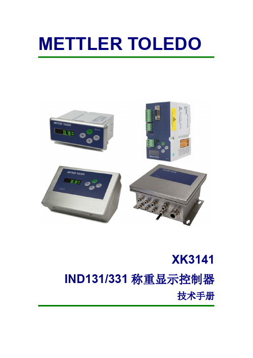
XK3141 IND131/331 称重显示控制器
技手册
目录
第 1 章 引言 .................................................................................................................................... 1 概述 .......................................................................................................................................... 1 性能指标........................................................................................................................... 1 型号 .......................................................................................................................................... 2 规格 .......................................................................................................................................... 2 危险场合的使用.....................................
sitemaster S331天馈线测试仪使用指南
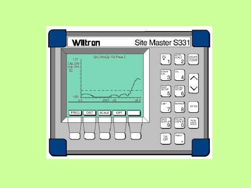
WILTRON SITE MASTE S331测试仪使用指南一、Site Master 331测试仪操作键示图二、测试仪表预调1. 选择频率范围-按ON按钮打开SiteMaster。
-按FREQ 软键。
-然后按F1 软键。
-输入天线系统的下限(“Lower”)频率MHz值,按ENTER键。
-再按F2 软键。
-输入天线系统的上限(“Higher”)频率MHz值,按ENTER键。
-在显示区域显示新的开始与结束值的地方检查频率数值范围FREQ scale。
-按MAIN 软键进入主菜单。
2. 测试仪表较准Open---开路器Short---短路器Load---负载器-将测试口扩充电缆(the test port extension cable)连到测试端口。
-按START CAL 键。
-连接标记为“OPEN”端的Open/Short器到测试扩充电缆的末端,然后按ENTER。
Result: 在测试处理过程中“Measuring OPEN”(测试开路)的信息将显示在屏幕上。
-连接标记为“SHORT”端的Open/Short器到测试扩充电缆的末端,然后按ENTER。
Result: 在测试处理过程中“Measuring OPEN”(测试开路)的信息将显示在屏幕上。
-连接“PRECISION LOAD ”(负载器)到测试扩充电缆的末端,然后按ENTER。
Result: 测量后,“Measuring LOAD”的信息显示在屏幕上,“Calculating”显示约8秒-校准完毕后, 从测试扩充电缆取下“PRECISION LOAD”器。
3. 输入天馈线的参数-按DIST 软键。
-按MORE 软键。
-按LOSS 键。
-输入要测试的天馈线类型的每米的损耗dB值(see Table 23) ,然后按ENTER.注意: 只有采用供货商提供的正确值,才能保证测试结果的可靠性。
-再按PROP V 软键。
-输入relative velocity (see Table 23) 测试天馈线的类型,然后按ENTER键。
高压测试仪使用培训教材

高压测试仪使用培训教材(CH-3315/3316 Hi-Pot Tester)制作:朱湘元审核:核准:2009年6月9日高压测试仪前面板功能介绍6354217914131211108高压测试仪后面板功能介绍364512高压测试仪前面板功能介绍1.电源开关---POWER;2.启动测试键---TEST(按下便属于测试状态,各项判定功能此时同时启动);3.重置按键---RESET(按下此键时重新恢复到预备测试状态并清除所有的判定);4.低压测试接线及输出端---LOW(此端等于外壳接地端);5.高压测试接线及输出端---H.V(此端为危险端!尤其当OUTPUT LED灯闪烁时表示有高压输出千万不可触摸!最高电压为6KV!);6.高压输出测试状态指示灯(OUTPUT LED);7. 测试判定结果显示区(PASS---良品、FAIL---不良品);8.上、下、左、右功能键---CURSOR(改变设定数值增减选择);9.确认键---ENTER,在设定状态下所输入各项参数变动的确认;10.测试端归零按键---OFFSET,在不同测试状态下将测试导线或测试线之漏电流作归零;11.系统参数设定键---SYSTEM(改变设定本测试机介面卡设定状态、各项特殊测试之设定参数、设定本测试机恢复出厂设定状态、校正本测试机等功能;12.退出键---EXIT(在设定状态下,按此键退出测试参数设定状态);13.程序编辑键---PROG(进入参数设定状态,按下此键显示器显示各项设定参数,且待设定项目闪动,此时本机处于设定或修改各项测试参数);14.屏幕显示(LCD DISPLAY),显示各项参数设定画面状态及各项测试数值判定结果画面;1.AC INPUT (AC电源插座及保险丝座,为三线式电源及保险丝插座);2.STATUS SIGNAL OUTPUT(测试结果讯号输出端,此输出端为一接点开关),PASS ----当本测试机判定待测物为良品时此输出短路;FAIL ----当本测试机判定待测物为不良品时此输出短路;TEST ----当本测试机处于测试状态下时此端会短路可利用此短路现象控制外部讯号;3.VOLTAGE SELECTOR(输入电源切换开关,改变本测试机输入的交流电源),其中使用的交流电源有以下四种:A.115V 适用电压范围90 ~125V AC;B.230V 适用电压范围194 ~250V AC(中国使用电压范围);4.FAN(直流风扇,为外抽式风扇以降低仪器之内部温度);5.GND Terminal(安全接地的端子,假如本测试机没有确实的接地,当电源的电路与地端短路或者任何设备的连接线与地端短路时,测试机的外壳可能将会有高电压的存在,这是非常危险的,只要任何人在上述的状态下触摸,将有可能造成触电事故的发生,因此务必接好安全接地端子至大地);6.REMOTE Connector---遥控插座(此插座遥控控制讯号的输入端,其所控制之讯号为TEST与RESET以及RMT-ENABLE等讯号);高压测试仪后面板功能介绍高压测试仪使用步骤及说明高压测试仪设定步骤如下:1.选择测试步骤:1~3 STEP;2.设定耐压、绝缘测试状态:AC/DC/IR;3.设定耐压测试所需电压:100V~5000Vac(DC6000V);4.设定绝缘测试所需电压:100V~1000Vdc);5.设定漏电电流判定上限值:0.10~12.00mA(DC5.00mA);6.设定漏电电流判定下限值:0.05~1/2的漏电流上限值mA或0.00mA(OFF);7.设定绝缘电阻判定上限值:0~2000 MΩ(0MΩ=OFF );8.设定绝缘电阻判定下限值:1~2000 MΩ(但不能超过上限设定值);9.设定测试所需时间:0.5~99.9Sec;10.上升至设定电压所需时间:0.0~99.9Sec或0.0S(OFF);11.ARC检测值的设定:1.0~12.00mA(DC1.0~5.0mA)或0.00mA (OFF);高压测试仪使用步骤及说明高压测试仪测试步骤如下:1.连接待测物(首先确定无电压输出,且DANGER灯不亮,然后把地电位用的黑色测试线插入主机LOW端,再把红色高压测试线插入主机HV.OUT端—连接时一定要确定主机无高压输出再进行连接!!!);2.按下RESET键准备测试(按下此键时高压测试仪才处于准备测试状态下,如在参数完全都设定后没有按下此键,则无法启动测试,且每次改变任何状态或数值后都必须同样按下此键才能启动测试!);3.按下TEST键启动测试(按下此键时则意味着已经启动测试高压,此时DANGER指示灯会闪烁,警告现为测试状态且有高压输出,电压、会读取输出电压值,电流表会检测漏电电流值,计时器同时做到倒数计时的工作);4.良品判定(当测试时间终了时测试电压即被截止,没有不良判断产生则判断为良品,显示器并显示PASS字样,然后PASS输出信号动作,蜂鸣器同时动作,其动作时间大约200mS左右);5.不良品判定(当测试中如检测漏电电流值超过所设定之漏电电流上限值或是低于所设定之下限值时,主机就判定为FAIL并立即截止高压输出,且显示器会出现FAIL字样及显示为何种不良判定(HI或LO或ARC Limit),后板FAIL输出讯号,蜂鸣器同时动作并持续动作直到主机被按下(RESET)键为止;6.在任何情况下,想终止测试只须按下重置键(RESET)即可;高压测试仪保养及环境要求一、保养(1)、该高压测试仪有6000V高压产生!!!,精密元件等组成,必须小心操作及储存;(2)、清洁时必须用柔软的布清洁(关机且不通电状态下进行!!!);(3)、底面盖都可以用螺丝刀取下(关机且不通电状态下进行!!!);(4)、储存额定温度应在:-20℃-70℃(-4℉-158℉),≦80%RH ;二、环境要求(1)、操作温度:5℃±35℃(41℉-95℉);(2)、操作湿度:20%RH-80%RH;(3)、额定使用温度:0℃-40℃(32℉-104℉);(4)、额定使用湿度:20%RH-80%RH;(5)、储存温度:-20℃-70℃(-4℉-158℉),≦80%RH ;高压测试仪使用注意事项1使用前注意事项:本测试机有6000V DC的高压送至外部测试,如因任何不正确或错误的使用本测试机,将会造成意外事故发生,甚至死亡!!1.感电及触电:为了预防触电事故的发生,在使用本测试机前建议先戴上绝缘的橡胶手套再从事测试有关的工作;2.接地:在本测试机的后板外壳上有一个安全接地的端子,请用适当的工具将此接地端确实的进行连接到大地;3.连接测试线于LOW端:将黑色的测试线连接至LOW端,当本测试机在使用的情况下任何时间都必须检查此测试线是否已连接好或松动、掉落,当欲用测试线连接测试物时,请先以LOW端之测试线先接上待测物(此时已接上主机之LOW端)假如LOW端的测试线连接不完全或掉落时是非常危险的,因整个待测物上将有可能会被充满高压电。
DT-3310 3311 3312 316 316型号的AC DC笼测量仪说明书

DT-3310/3311/3312/3 316AC, AC/DC Clamp MetersDT-3310 Series Professional 1000A AC Clamp Meters provide many functions for professional AC current and voltage measurements including resistance, capacitance and diode test, etc. Withmid-size and tear-drop shaped jaw, it is easy to use in crowded cable areas and other tight places.Features DT-3310 DT-3311 DT-3312 DT-3316 Current measurements AC AC AC AC/DC Digital display counts 4000 4000 4000 4000 Electronic overload protection * * * * Continuity buzzer & Diode check * * * * Data Hold function * * * * Peak Hold * DCA Zero function * * Auto Power Off * * * * Low battery indication * * * * Display with backlight * * * * 2.16” (55mm) Clamp jaw opening * * * * Size (H x W x D): 270mm x 107mm x 50mmWeight: 554gSpecificationsFunction MaxRangeBasicAccuracyMax.ResolutionDT-3310 DT-3311 DT-3312 DT-3316AC Current 2000 A ±(2.5%+5d) 100mA 1000A 1000A * * DC Current 2000 A ±(2.5%+5d) 100mA * AC Voltage 1000V ±(1.0%+4d) 0.1mV * * * * DC Voltage 1000V ±(0.5%+4d) 0.1mV * * * * Resistance 40MΩ ±(1.0%+2d) 0.1Ω * * * * Frequency 10MHz ±(1.2%+2d) 0.001Hz * * * * Capacitance 40mF ±(3.0%+5d) 0.01nF * *ApplicationsAccessories: T est leads, gift box with carrying case, 9V battery.CEMDT-3353DIGITAL T-RMS AC/DC CLAMP ONPOWER METERThis is a 9999 counts Backlit LCD display, Digital T-RMSAC/DC clamp on power meter. It is used to measurepower parameters like kW, kVA, power factor for threephase and single phase loads.It has USB PC Interface for Data Collection and Storage.Has max /min Record Function, Data Hold Function, DataLogging facility, Non Contact Voltage Detector Function,Low Battery and Overload Indication.Measures AC Current upto 1000A T-RMS, DC Voltage,Active Power, Apparent Power, Reactive Power, PowerFactor, Phase Angle Active Energy. Thease can be doneon three Phase and single Phase Location.Temperature Measurement is also possible.Contact :CEM INSTRUMENTS (INDIA) PVT. LTD.CEM INSTRUMENTS HEADQUATER & FACTORYGeneral SpecificationsItem DescriptionQty 1English Operating Manual 1 piece 2Red Test Lead 3 piece 3Black Test Lead 1 piece 4Red Alligator Clip 3 piece 5Black Alligator Clip 1 piece 6USB Interface Cable 1 piece 7Software 1 piece 8Tool Box 1 piece 99V Battery 1 piece 10Test Certificate1 pieceSafety InformationThis Meter complies with the standards IEC61010: in pollution degree 2, overvoltage category (CAT. III 600V , CAT IV 300V) and double insulation.CAT. III: Distribution level, fixed installation, with smaller transient overvoltages than CAT.IV: Primary supply level, overhead lines, cable systems etc.Contact :CEM INSTRUMENTS (INDIA) PVT. LTD.CEM INSTRUMENTS HEADQUATER & FACTORYElectrical Specifications Accuracy: (a% reading + b digits), guarantee for 1 year.Operating temperature: 23±5Operating humidity: 45~75%R.HRange Resolution Accuracy Allowable Maximumoverload protection voltageInputImpedanceFrequency Range 100V 0.1V±(1.2%+5)750 RMS10M50Hz~200Hz400V 750VRange ResolutionAccuracyAllowable Maximumoverload protection currentFrequency Range40A 0.1A ±(2%+5)1000A RMS50Hz~60Hz100A 400A 1000A1ACurrent / VoltageVoltages Range100V 400V 750V Current Range 40A 4.00KW 16.00KW 30.00KW 100A 10.00KW 40.00KW 75.00KW 400A 40.00KW 160.0KW 300.0KW 1000A100.0KW 400.0KW 750.0KW Accuracy ±(3%+5)Resolution<1000KW: 0.01KW 100kW: 0.1KWCurrent / VoltageVoltages Range100V 400V750VCurrent Range40A 4.00KVAr 16.00KVAr 30.00KVAr 100A 10.00KVAr 40.00KVA 75.00KVAr 400A 40.00KVAr 160.0KVAr 300.0KVAr 1000A100.0KVAr400.0KVAr750.0KVArAccuracy ±(3%+5)Resolution<1000KVAr: 0.01KVAr 100kW: 0.1KVArRange Accuracy Resolution Measuring Condition 0° - 90°(capacitive or inductive)±2°1°The minimum measuring current 10AThe minimum measuring voltage 45V0° - 90° (capacitive or inductive)For reference onlyMeasuring current less than 10A ORMeasuring voltage less than 45VA. AC Voltage (True RMS)Range ResolutionAccuracy 50Hz~200Hz1Hz±(0.5%+5)B. FrequencyC. AC Current (True RMS)D. Active Power ( W=V x A x COS θ)Current / VoltageVoltages Range100V 400V 750V Current Range 40A 4.00KVA 16.00KVA 30.00KVA 100A 10.00KVA 40.00KVA 75.00KVA 400A 40.00KVA 160.0KVA 300.0KVA 1000A100.0KVA 400.0KVA 750.0KVA Accuracy ±(3%+5)Resolution<1000KVA: 0.01KVA 100kW: 0.1KVAE. Apparent Power (VA = V x A)F . Reactive Power (Var = V x A x SIN θ)Range Accuracy Resolution Measuring Condition 0.3 - 1(capacitive or inductive)±0.0220.001The minimummeasuring current 10A The minimummeasuring voltage 45V 0.3 - 1(capacitive or inductive)For reference onlyMeasuring current less than 10A ORMeasuring voltage less than 45VG. Power Factor (PF = W / VA)H. Phase Angle (PG=acos (PF))Range Accuracy Resolution 1~9999kWh ±(3%+2)0.001kWhI. Active Energy (kWh)Remarks:● Allowable maximum overload protection voltage: 750V RMS●Allowable maximum overload protection current: 1000A RMSDT-3385/3386Professional Heavy Duty AC, AC/DC True RMS Autoranging Clamp Meters with Flexible ClampThe 3385 series clamp meters offer all needed features for measurement, design for perfectly handhold and tight place testing. A large backlit display (on most models) is easy to see and a handy Display Hold keeps measurements on the display. Flexible current probe expands the measurement range to 2500ACA.l Double molded plastic housingl True RMS measurement for ACV & ACAl Flexible current probe expands themeasurement range to 3000 ACAfor all modelsl Dual type K inputs for temperaturemeasuring support moreapplication. (3387/3388)l Flexible current probe expands themeasurement range to 3000 ACASpecifications Function Max. Range Basic Accuracy 3385 3386 Voltage DC 1000V ±(0.1%+4d) * * Voltage AC 1000V ±(1.0%+3d) * * Current DC 1000A ±(2.5%+5d) * Current AC 1000A ±(2.5%+5d) * * Resistance 50MΩ ±(3.0%+5d) * *Temperature 1000ºC/ 1832ºF ±(1.0%+2.5°C/4.5°F)* *Capacitance 5mF ±(3.5%+10d) * * Frequency 10MHz ±(0.3%+2d) * *ACA flexibleclamp3000A ±(2.8%+8d) * * Continuity check Buzzer sounds at 50ΩDiode test Test current 0.3mAFeatures 3385 3386Current measurement AC AC/DCLCD display counts withbacklight50000 500003000A ACA Flexible clamp * *AC True RMS * *Flashlight * *Data Hold & Peak Hold * *Max /Min * *REL (Zero) Function * *Auto Power Off * *Low battery indication * *1.9” (48mm) Jaw opening * *NCV Detection & flashlight * *Inrush Current * *Size(HxWxD): 230mm x 76mm x 40mmWeight: 315gAccessories: T est leads, gift box with carrying case, Temperature probe and9V battery.CEMModel 9380Model 9381 The 9380/9381/9382/9383 series clamp meters providing fast A/D converting sampling time, highaccuracy, built-in datalogging offer all needed features for measurement. It is with modern bodies and jawsdesign for perfect handheld and tight place testing. A large backlit display (on most models) is easy to seeand a handy data hold keeps measurements on the display.Double molded plastic housingTrue RMS measurement for ACV & ACAFlexible current probe expands the measurementrange to 3000 ACA (9383)EMC & LVDEN: 61326EN: 61010-1EN: 61010-02-032EN: 61010-02-033DOUBLEMOLDED。
- 1、下载文档前请自行甄别文档内容的完整性,平台不提供额外的编辑、内容补充、找答案等附加服务。
- 2、"仅部分预览"的文档,不可在线预览部分如存在完整性等问题,可反馈申请退款(可完整预览的文档不适用该条件!)。
- 3、如文档侵犯您的权益,请联系客服反馈,我们会尽快为您处理(人工客服工作时间:9:00-18:30)。
o23 数字输出 1,运行时间
继电器 2 的值
o24 数字输出 2,运行时间
继电器 3 的值
o25 数字输出 3,运行时间
继电器 4 的值
o26 数字输出 4,运行时间
制冷剂设置
o30 制冷剂
制冷开始前,必须选择相应的制冷剂:
1=R12,2=R22,3=R134a,4=R502,5=R717,6=R13,7=R13b1,8=R23,9=R500
10=R503,11=R114,12=R142b,13=自定义,14=R32,15=R22716=R401a
17=R507,18=R402A,19=R404A,20=R407C,21=R407A,22=R407B,
23=R410A,24=R170,25=R290,26=R600,27=R600a,28=R744,29=R1270
使用手册
ADAP-KOOL®
机组能量控制器 EKC 331T
简介
应用 EKC331T 控制器用于小型制冷系统中压缩机或冷 凝器的能量控制,每个控制器最多可控制四个等 大小能量级。
优势 • 专利的中性区控制技术 • 顺序运转或轮换运转
功能 • 控制
至多可以控制 4 个继电器输出。控制的启停是 基于压力传感器信号与设定参考值之间的比较 关系。 • 继电器模块 因为有可能将控制器作为继电器模块来使用, 所以继电器可以通过外部的电压信号来控制其 开/关。 • 报警功能 当达到预设的报警值时,继电器被触发。 • 数字输入 数字输入可被用做: - 夜间操作模式时,提升吸气压力 - 热回收时,提升冷凝压力 - 外部启停控制 - 安全回路监控 • 具备数据通讯功能
显示 压力传感器的信号将被转换并显示为温度值 设置中也采用温度值
功能
能量控制 能量开启控制是由连接控制器的压力传感器(温 度传感器)信号及设定值控制的。 在参考值(REF)附近设立了一个中性区。在中 性区内,能量即不会被开启也不会被关闭。 在中性区之外(以+zone 和-zone 命名的阴影区 内),如果发现压力(温度)变化偏离了中性 区,则能量就会根据设定的延迟时间被开启或者 关闭。 但是,如果压力(温度)变化的趋势正朝向中性 区,则控制器就不会对能量开启操作进行任何改 变。 如果能量调节发生在阴影区之外(即以++zone 和 --zone 定义的区域),能量开启的变化幅度将会 比在阴影区内时更快。 开启操作既可以是顺序的也可以是循环的。
轻触上键,重设报警器,同时可以看到显示器上有显示。
重设报警
调到“ON”的位置,所有的报
警被重置。
报警继电器
可以查看报警继电器状态。
(ON 表示带报警的操作。)
通过数据通讯,每个报警的重要
性都可以被定义。所有的报警设
定都在“Alarm destination”菜单
中设定的。参见第 11 页。
其它
其它
外部信号
30=R417A 提示:制冷剂的错误选择可能导致压缩机损害
手动控制
o18 手动控制
从该菜单中,继电器可以设置成手动开启或关闭。“OFF”,设置数
只有当“手动控制”被置于
字 1 到 4 会开启对应的继电器。继电器总是从 1 号开始。手动运行
“ON”的位置上时,才可以对
时,会显示“- -x”,x 代表数字 0~4。
3
使用手册 RS8CU202 © Danfoss 01-2003
EKC 331T
功能浏览
功能 正常显示 正常状态下,屏幕上显示的是压力/温度传感器传来的信号值。如果 控制器被用做继电器模式,就会显示Uin的数值。 压力控制 控制设定值 控制是基于设定值的。通过 r02 和 r03 可以限制/固定设定值的变化 (同时按下两个按键进入菜单设置。) 中性区 在参考值附近有一个中性区。参见第二页。 参考值 当信号由 DI 端口输入时,参考值可以用固定值进行平移。这时,控 制就基于该固定值加上某一设定值。(参考对 DI 输入的定义。) 按下键就可以看到总的参考值 设定值的限定 对控制器的参考值设定范围可以进行限制,以避免意外设定一个太小 或者太大的值——因为这可能导致系统的损坏。这样,参考值只能被 设定在两个值之间。
4 上(继电器 1 和 2 属于第一台压缩机,继电器 3 和 4 属于另一
台。)上面提到的“继电器最小开启时间”不适用于带有卸载器的
情况。两个卸载器都是在压缩机关闭之前被关闭。
卸载器的开启和关闭模式
c09 卸载器
(只与第三种耦合模式有关,见上。)
(开启 = 0)
当压缩机能量需求增加或减少时,两个卸载器的继电器可分别设定为
上偏差
A10 最大压力/温度
高温/高压时报警动作,设定值为绝对值。参见紧急程序,第 7 页。
下偏差
A11 最小压力/温度
低温/低压时报警动作,设定值为绝对值。参见紧急程序,第 7 页。
报警延迟
A03 报警延迟
如果两个限定值中的一个被超过,计时器就会启动。直到设定延迟时
间超过后,报警才会被触发,延迟时间以秒计。
进行设置。(继电器总按照数字顺序来使用的。)
压力传感器的工作范围
如果两个值是通过 AKM 进行设
每个压力传感器有自己的使用范围,其工作范围须在控制器内进行设
置,须以 bar 为单位
定(比如:-1 到 12 bar)。如果显示选用“℃”,该设置须以 bar 为
单位,如是“ºF”,则设置须以 psig 为单位 最小值 最大值
如果需要对控制器内设定的参数进行保护,可以设定一个 0 到 100 的
数字做为代码。如果不需要,可以设定“OFF”,取消此功能。
运行状态
当控制器完成了某些控制动作后,进入待命状态。如果需要了解这些
EKC 状态
待命状态,通过轻触上键(持续 1 秒钟),就可以看到这些运行的状
(0 = 控制)
态,对应的状态代码会显示在显示器上。
16
报警信息
报警
6
使用手册 RS8CU202 © Danfoss 01-2003
EKC 331T
A1:高温报警(A10) A2:低温报警(A11) A11:未选择制冷剂(o30) A12:根据数字输入(DI)的中断信号要求,控制功能被停止 E1:控制器报错 E2:控制信号超出范围(短路/断开)
高温报警 低温报警 未选择制冷剂 DI 报警 控制器故障 超出范围
Rx=随机继电器 h=小时数
如果控制器控制的是两台压缩机,且每台压缩机均带有 一级卸载,则可使用如下功能: 继电器 1 和 3 连接到压缩机电机 继电器 2 和 4 连接到卸载 继电器 1 和 3 轮换运行,两个继电器的运行时间相等
继电器模块 控制器有时也可以被用做继电器模块。这时,继电 器是由接收到的电压信号控制的。 基于对信号的定义以及使用的继电器的数量,继电 器可以根据信号被分配使用。 每一个开启/闭合动作都有一定的延迟,以便保证不 再需要该操作时,继电器就不会开启或者闭合。
c12 ++Zone s
中性区以下控制段
c13 -Zone K
中性区以下控制段内多级关闭延迟时间
c14 -Zone m
“-Zone”区以下控制段内多级关闭延迟时间
c15 --Zone s
报警
报警设置
控制器可以在不同的情况下进行报警。报警时,控制器面板上所有的
发光二极管(LED)都会闪烁,且报警继电器开启。
每个状态代码的意义如下:
S2:当继电器运行时,至少运行 x 分钟(参见 C01)
2
S5:同一个继电器再次被开启必须不少于 x 分钟(参见 C07)
5
S8:x 分钟后,下一个继电器才可以被开启(参见 C11-C12)。
8
S9:x 分钟以后,下一个继电器才可以被闭合(参见 C14-C15)。
9
S16:因手动运行,控制被停止(通过设置 o18)
(闭合 = 1)
开启(setting = 0)或关闭(setting = 1)。
中性区控制设置
c10 +Zone K
中性区以上控制段
中性区以上控制段内多级启动延迟时间
c11 +Zone m
4
使用手册 RS8CU202 © Danfoss 01-2003
EKC 331T
“+Zone”区以上控制段内多级启动延迟时间
1.顺序:首先继电器 1 开启,然后继电器 2 开启…而关闭是以相反
顺序进行的(第一个开启的最后一个关闭)。
2.轮换:每个步骤的运行时间是相同的(具有最少运行小时数的继
电器比其他的继电器先开启或者关闭)。
3. 轮换(带卸载):此项功能只适用在两台压缩机且每台只带一级卸
载。轮换操作是在继电器 1 和 3 上实现的,卸载连接到继电器 2 和
以与其他控制器一道用于ADAPKOOL®制冷控制系统中。
在进行设置之前,必须保证通信模块已被加装到控制器上,并且通信
电缆业已连接完毕。
有关安装内容参见文件“RC.8A.C”。
地址可以设为 1 到 60 之间的任何一个数字。
o03
当菜单被设定在“ON”的位置时,地址就会被发送到网关。
o04
进入密码
o05
0:℃
设置=“C-b”:℃
1:ºF
设置=“F-p”: ºF
(在 AKM 软件中,只能使用℃
作为单位)
能量
能量
运行时间
为防止频繁启/停,需要对开启和关闭动作设置延迟。
继电器最少开启时间。
c01 最少开启时间
同一个继电器两次开启的最小时间间隔。
c07 最小循环时间
耦合
c08 分步模式
开启和关闭可以通过三种方式发生:
6:0-5 V 其它控制信号;
7:5-10 V 其它控制信号;