松下继电器选型一览
继电器DS2继电器
DS2继电器DS2继电器产品型号: DS2Y/DS2E产品简介:NAIS:品 牌 :松下类 型 : 信号继电器系 列 : DS2Y系列型 号 : DS2Y-S-DC24V 外形尺寸(mm):20.0×9.9×9.3mm(L×W×H)重 量 : 2g 触点参数:触点形式: 2C(DPDT)触点负载: 2A30VDC, 阻 抗: ≤50mΩ额定电流: 2A 电气寿命:≥10万回机械寿命:≥1亿回线圈参数: 阻值(士10%):2880Ω 线圈功耗:200mW 额定电压:DC24V 吸合电压:DC 16.8V 释放电压:DC2.4V 工作温度:-40℃~+85℃ 绝缘电阻:≥1000MΩ 线圈与触点间耐压:1000VAC/1分钟触点与触点间耐压:1000VAC/1分钟联系,具体系列产品详细介绍:NAIS:品 牌 :松下类 型 : 信号继电器系 列 : DS2Y系列型 号 :DS2Y-S-DC24V 外形尺寸(mm): 20.0×9.9×9.3mm(L×W×H)重 量 : 2g触点参数:触点形式: 2C(DPDT)触点负载: 2A30VDC, 阻 抗: ≤50mΩ 额定电流: 2A电气寿命:≥10万回机械寿命:≥1亿回线圈参数: 阻值(士10%):2880Ω 线圈功耗:200mW 额定电压:DC24V吸合电压:DC 16.8V 释放电压:DC2.4V 工作温度:-40℃~+85℃ 绝缘电阻:≥1000MΩ线圈与触点间耐压:1000VAC/1分钟触点与触点间耐压:1000VAC/1分钟联系,具体系列供应松下DS2Y系列1:抗电磁干扰能强,可实现高密度安装。
2:耐冲击电压1500V.FCC规格标准,实现耐高压。
3:包金双接点,而且低接点振动,可以发挥高接触可靠性。
4:品种齐全,用途广泛。
触点有效负载:30VDC 1A 线圈电压:(DC)1.5,3,5,6,9,12,24,48V 线圈功耗: 200mW180mW 外形尺寸:20×9.9×9.3 触点参数:触点形式:2C(DPDT)触点负载:2A30VDC, 阻抗:≤50mΩ 额定电流:2A电气寿命:≥10万回机械寿命:≥1亿回线圈参数: 阻值(士10%):720Ω 线圈功耗:200mW 额定电压:DC12V 吸合电压:DC8.4V 释放电压:DC1.2V 工作温度:-40℃~+85℃绝缘电阻:≥1000MΩ 线圈与触点间耐压:1000VAC/1分钟触点与触点间耐压:1000VAC/1分钟具体系列型号:DS2Y-S-DC1.5V,DS2Y-S-DC3V,DS2Y-S-DC5V,DS2Y-S-DC6V,DS2Y-S-DC9V,DS2Y-S-DC12V,DS2Y-S-DC24V,DS2Y-S-DC48V,DS2Y-SL2-DC1.5V,DS2Y-SL2-DC3V,DS2Y-SL2-DC5V,DS2Y-SL2-DC6V,DS2Y-SL2-DC9V,DS2Y-SL2-DC12V,DS2Y-SL2-DC24V,DS2Y-SL2-DC48V;型号: DS2Y-S-DC1.5V,DS2Y-S-DC3V,DS2Y-S-DC5V,DS2Y-S-DC6V,DS2Y-S-DC9V,DS2Y-S-DC12V,DS2Y-S-DC24V,DS2Y-S-DC48V,DS2Y-SL2-DC1.5V,DS2Y-SL2-DC3V,DS2Y-SL2-DC5V,DS2Y-SL2-DC6V,DS2Y-SL2-DC9V,DS2Y-SL2-DC12V,DS2Y-SL2-DC24V,DS2Y-SL2-DC48V;松下DS2E-SL2-3V系列继电器:DS2E-5V,DS2E-12V,DS2E-24V,DS2E-S-5V,DS2E-S-12V,DS2E-S-24V,DS2E-SL-5V,DS2E-SL-12V,DS2E-SL-24V,DS2E-SL2-5V,DS2E-SL2-12V,DS2E-SL2-24V,DS2E-M-5V,DS2E-M-12V,DS2E-M-24V,DS2E-ML-5V,DS2E-ML-12V,DS2E-ML-24V,DS2E-ML2-5V,DS2E-ML2-12V,DS2E-ML2-24V,全新原装现货。
松下PLC编程手册中文版
1 - 11.1 继电器、存储器和常数表1.1.1 FP0/FP-e编号方式项目FP0-C10/C14/C16 FP-eFP0- C32FP0- T32C功能外部输入继电器(X)208点(X0~X12F) 根据外部输入通断。
外部输出继电器(Y)208点(Y0~Y12F) 外部输出通断。
内部继电器(R) (*注释2) 1008点 (R0~R62F) 只在程序内部通断的继电器。
定时器(T) (*注释2) 如果TM 指令定时到时,则相同编号的触点接通。
计数器(C) (*注释2)144点(T0~T99/C100~C143) (*注释1)如果CT 指令计数到,则相同编号的触点接通。
继电器特殊内部继电器(R)64点(R9000~R903F) 为根据规格条件通断的继电器,并用于标志。
外部输入继电器(WX)13字(WX0~WX12) 以1个字(16位)的数据指定16个外部输入点。
外部输出继电器(WY)13字(WY0~WY12) 以1个字(16位)的数据指定16个外部输出点。
内部继电器(WR) (*注释2)63字(WR0~WR62) 以1个字(16位)的数据指定16个内部继电器点。
数据寄存器(DT) (*注释2) 1660字(DT0~DT1659)6144字 (DT0~ DT6143)16384字 (DT0~ DT16383)被用于程序的数据存储区。
数据被处理为16位(1个字)。
定时器/计数器 设定值区(SV) (*注释2)144字(SV0~SV143)用于存储定时器的设定值以及计数器的缺省值。
以定时器/计数器数字进行存储。
定时器/计数器经过值区(EV) (*注释2)144字(EV0~EV143)用于存储通过定时器/计数器操作的经过值。
以定时器/计数器数字进行存储。
特殊数据寄存器(DT)112字(DT9000~ DT9111)112字(DT90000~DT90111)用于存储特殊数据的数据存储区。
不同的设置和错误代码将被存储。
松下继电器

• Terminal layout (.100, inch grid)
6.4 .252
7.62 .300
6 .236 1.2 .047 0.8 .031 2.54 2.54 2.54 .100 .100 .100
mm inch
Tolerance: ±0.1 ±.004
2.54 .100
2.54 2.54 .100 .100
0.12 A 70 Ω 120 Ω 45 pF
Typical Maximum
Output capacitance (Typical) Off state leakage current LED forward current* LED reverse voltage* Peak forward current Power dissipation* • Input
Continuous load current • Output Peak load current Power dissipation* ON resistance
0.5 A 0.12 A 0.1 A
0.35 A
0.3 A 0.16 A 0.12 A 0.1 A 0.04 A
0.3 A 300 mW 17 Ω 25 Ω 45 pF Max. 1 µA 50 mA 3V 1A 75 mW 0.9 mA 3.0 mA 0.4 mA 0.85 mA 1.14 V 1.5 V 0.23 ms 0.5 ms 0.04 ms 0.2 ms 350 mW 1,500 V AC
PhotoMOS Selector Chart
GU SOP Type
1a Types AC/DC Type 4-Pin • Type of relay
继电器的选用原则
安装尺寸要求
装
焊接方式
手工焊接、波峰焊、回流焊等、 是否清洗?
√ 安装方式
安装间隙
间隙、紧贴?
√
其它
安全认证 特 殊要求 和情 况
UL、VDE、TUV、CQC 等? 客户要求
√ 地域 √ 客户要求
以下对上表中的一些项目进一步说明 1 触点 1.1 触点负载 确定继电器所能承受的负载是否满足使用要求时,除了需要确定负载的大小,还要确定实际负载的
宏大继电器
继电器使用及注意事项
时要注意极性、脉冲宽度。 g) 对于极化继电器,请注意其线圈电压的极性(+、-)。 除此之外还有其它注意事项,以 下将大致参照“表 1 继电器的选用原则”的顺序逐一说明。
1 触点的注意事项
触点是继电器中最重要的结构件,触点的使用寿命受触点材料、触点上的电压及电流值(特别是接通时及 断开时的电压、电流波形)、负载种类、切换频率、环境情况、接触形式、触点回跳现象等的影响,触点失效多 以触点的材料转移、粘连、异常消耗、接触电阻增大等故障现象出现,使用时需要注意。
为更好的使用继电器,请参考以下记述的有关触点的注意事项。
1.1 负载 一般在产品说明书中记载了阻性负载的大小,但只有这些是不够的,应该在实际的触点电路里进行试验确 认。 产品说明书中记载的最小负载并非继电器可以可靠切换的标准下限值,这个值由于通断频率、环境条件、 被
√
√
外壳
壳和底板内。可进行水洗。
密封胶 底座
宏大继电器
密封型
金属外壳
金属外 壳 与金属 底座 间实 现
金属融熔 式接焊
金属封闭,引出端与底座间用
√
玻璃封闭。继电器内部气体向
松下HN继电器(中文)hn

吸合电压 (at20℃)
释放电压 (at20℃)
AC12V AC24V AC100/110V AC110/120V AC200/220V AC220/240V
额定电压的 80%V以下 (初始)
额定电压的 30%V以上 (初始)
额定励磁电流[±20%]
50Hz
60Hz
93mA
A
HN /HN 继电器
继电器端子台
可以在从检测到功率的广泛领域内使用的细长型、小型通用继电器。
■特长
■用途
1.细长型·小型化尺寸。
与过去的新产品(HC/HJ)相比,实现了 20%的细长型·小型化。 (在端子台插入的状态下)
控制盘、电源装置、成形机、工作机械、溶 接机、农业机械、办公设备、自动贩卖机、通 信设备、游戏机等
2C 订购品号 AHN22112 AHN22124 AHN211X0 AHN211Y0 AHN22105 AHN22106 AHN22148 AHN221X0 AHN221X1 AHN21112 AHN21124 AHN211X1 AHN211Y2
2C 订购品号 AHN22212 AHN22224 AHN22205 AHN22206 AHN22248 AHN222X0 AHN222X1
11.0/13.0mA
9.0/10.6mA
10.0/11.8mA
8.2/9.7mA
5.5/6.5mA
4.5/5.3mA
5.0/5.9mA
4.1/4.8mA
额定消耗电压
50Hz
60Hz
最大容许功率 (at20℃)
约1.1~约1.4VA
约0.9~约1.2VA
额定电压的 140%V
2.性能概要
规格 触点规格 额定
松下继电器
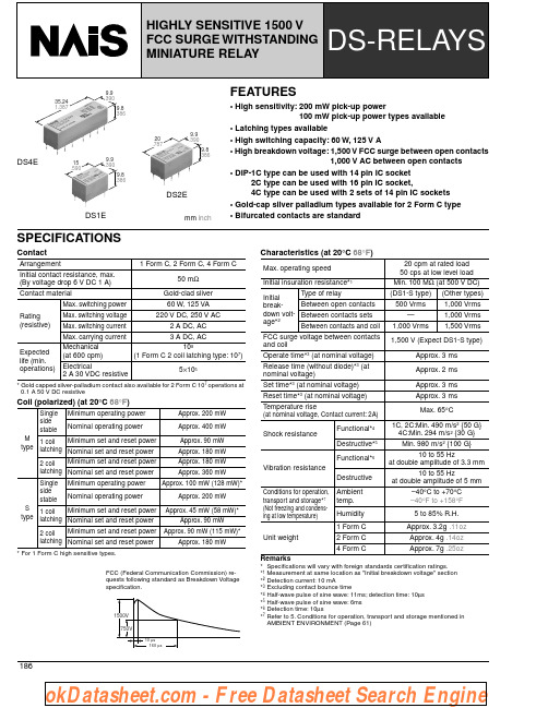
18635.241.387.390DS1E15.5909.9.390DS2E20.787.390FEATURES• High sensitivity: 200 mW pick-up power100 mW pick-up power types available• Latching types available• High switching capacity: 60 W, 125 V A• High breakdown voltage: 1,500 V FCC surge between open contacts1,000 V AC between open contacts• DIP-1C type can be used with 14 pin IC socket2C type can be used with 16 pin IC socket,4C type can be used with 2 sets of 14 pin IC sockets • Gold-cap silver palladium types available for 2 Form C type • Bifurcated contacts are standardSPECIFICATIONSContact* Gold capped silver-palladium contact also available for 2 Form C 107 operations at 0.1 A 50 V DC resistiveCoil (polarized) (at 20°C 68°F )* For 1 Form C high sensitive types.Characteristics (at 20°C 68°F )Arrangement 1 Form C, 2 Form C, 4 Form C Initial contact resistance, max.(By voltage drop 6 V DC 1 A)50 m ΩContact material Gold-clad sliverRating(resistive)Max. switching power 60 W, 125 VA Max. switching voltage 220 V DC, 250 V AC Max. switching current 2 A DC, ACMax. carrying current 3 A DC, AC Expected life (min.operations)Mechanical (at 600 cpm)108(1 Form C 2 coil latching type: 107)Electrical 2 A 30 VDC resistive5×105M type Single side stableMinimum operating power Approx. 200 mW Nominal operating powerApprox. 400 mW1 coil latchingMinimum set and reset power Approx. 90 mW Nominal set and reset power Approx. 180 mW 2 coillatching Minimum set and reset power Approx. 180 mW Nominal set and reset power Approx. 360 mWS type Single sidestableMinimum operating powerApprox. 100 mW (128 mW)*Nominal operating power Approx. 200 mW 1 coil latchingMinimum set and reset power Approx. 45 mW (58 mW)*Nominal set and reset power Approx. 90 mW2 coillatching Minimum set and reset power Approx. 90 mW (115 mW)*Nominal set and reset power Approx. 180 mWMax. operating speed20 cpm at rated load 50 cps at low level load Initial insuration resistance*1Min. 100 M Ω (at 500 V DC)Initialbreak-down volt-age*2Type of relay(DS1-S type)(Other types)Between open contacts 500 Vrms 1,000 VrmsBetween contacts sets—1,000 Vrms Between contacts and coil1,000 Vrms 1,500 Vrms FCC surge voltage between contacts and coil1,500 V (Expect DS1-S type)Operate time*3 (at nominal voltage)Approx. 3 ms Release time (without diode)*3 (at nominal voltage)Approx. 2 ms Set time*3 (at nominal voltage)Approx. 3 msReset time*3 (at nominal voltage)Approx. 3 ms Temperature rise(at nominal voltage, Contact current: 2A)Max. 65°CShock resistanceFunctional*41C, 2C:Min. 490 m/s 2 {50 G}4C:Min. 294 m/s 2 {30 G}Destructive*5Min. 980 m/s 2 {100 G}Vibration resistanceFunctional*610 to 55 Hzat double amplitude of 3.3 mmDestructive10 to 55 Hzat double amplitude of 5 mmConditions for operation, transport and storage*7(Not freezing and condens-ing at low temperature)Ambienttemp.–40°C to +70°C –40°F to +158°FHumidity 5 to 85% R.H.Unit weight 1 Form C Approx. 3.2g .11oz 2 Form C Approx. 4g .14oz 4 Form CApprox. 7g .25ozFCC (Federal Communication Commission) re-quests following standard as Breakdown Voltagespecification.Remarks*Specifications will vary with foreign standards certification ratings.*1Measurement at same location as "Initial breakdown voltage" section *2Detection current: 10 mA*3Excluding contact bounce time*4Half-wave pulse of sine wave: 11ms; detection time: 10µs *5Half-wave pulse of sine wave: 6ms *6Detection time: 10µs*7Refer to 5. Conditions for operation, transport and storage mentioned in AMBIENT ENVIRONMENT (Page 61)mm inch187TYPICAL APPLICATIONS• T elecommunication equipment • Office equipment• Computer peripherals • Security equipment• Measuring instrumentationORDERING INFORMATIONTYPESSingle side stable1 coil latching2 coil latchingNotes:1. Reverse polarity types available (add suffix-R).2. Standard packing: carton: 50 pcs.; case: 500 pcs.Nominal Voltage, V DCPart No.1 Form C 2 Form C 4 Form C M (400 mW) type1.5DS1E-M-DC1.5V DS2E-M-DC1.5V DS4E-M-DC1.5V 3DS1E-M-DC3V DS2E-M-DC3V DS4E-M-DC3V 5DS1E-M-DC5V DS2E-M-DC5V DS4E-M-DC5V 6DS1E-M-DC6V DS2E-M-DC6V DS4E-M-DC6V 9DS1E-M-DC9V DS2E-M-DC9V DS4E-M-DC9V 12DS1E-M-DC12V DS2E-M-DC12V DS4E-M-DC12V 24DS1E-M-DC24V DS2E-M-DC24V DS4E-M-DC24V 48DS1E-M-DC48V DS2E-M-DC48V DS4E-M-DC48V S (200 mW) type1.5DS1E-S-DC1.5V DS2E-S-DC1.5V DS4E-S-DC1.5V 3DS1E-S-DC3V DS2E-S-DC3V DS4E-S-DC3V 5DS1E-S-DC5V DS2E-S-DC5V DS4E-S-DC5V 6DS1E-S-DC6V DS2E-S-DC6V DS4E-S-DC6V 9DS1E-S-DC9V DS2E-S-DC9V DS4E-S-DC9V 12DS1E-S-DC12V DS2E-S-DC12V DS4E-S-DC12V 24DS1E-S-DC24V DS2E-S-DC24V DS4E-S-DC24V 48DS1E-S-DC48VDS2E-S-DC48V DS4E-S-DC48VNominal Voltage, V DCPart No.1 Form C2 Form C4 Form CM (180 mW) type1.5DS1E-ML-DC1.5V DS2E-ML-DC1.5V DS4E-ML-DC1.5V 3DS1E-ML-DC3V DS2E-ML-DC3V DS4E-ML-DC3V 5DS1E-ML-DC5V DS2E-ML-DC5V DS4E-ML-DC5V 6DS1E-ML-DC6V DS2E-ML-DC6V DS4E-ML-DC6V 9DS1E-ML-DC9V DS2E-ML-DC9V DS4E-ML-DC9V 12DS1E-ML-DC12V DS2E-ML-DC12V DS4E-ML-DC12V 24DS1E-ML-DC24V DS2E-ML-DC24V DS4E-ML-DC24V 48DS1E-ML-DC48V DS2E-ML-DC48V DS4E-ML-DC48V S (90 mW) type1.5DS1E-SL-DC1.5V DS2E-SL-DC1.5V DS4E-SL-DC1.5V 3DS1E-SL-DC3V DS2E-SL-DC3V DS4E-SL-DC3V 5DS1E-SL-DC5V DS2E-SL-DC5V DS4E-SL-DC5V 6DS1E-SL-DC6V DS2E-SL-DC6V DS4E-SL-DC6V 9DS1E-SL-DC9V DS2E-SL-DC9V DS4E-SL-DC9V 12DS1E-SL-DC12V DS2E-SL-DC12V DS4E-SL-DC12V 24DS1E-SL-DC24V DS2E-SL-DC24V DS4E-SL-DC24V 48DS1E-SL-DC48VDS2E-SL-DC48V DS4E-SL-DC48VNominal Voltage, V DCPart No.1 Form C2 Form C4 Form CM (360 mW) type1.5DS1E-ML2-DC1.5V DS2E-ML2-DC1.5V DS4E-ML2-DC1.5V 3DS1E-ML2-DC3V DS2E-ML2-DC3V DS4E-ML2-DC3V 5DS1E-ML2-DC5V DS2E-ML2-DC5V DS4E-ML2-DC5V 6DS1E-ML2-DC6V DS2E-ML2-DC6V DS4E-ML2-DC6V 9DS1E-ML2-DC9V DS2E-ML2-DC9V DS4E-ML2-DC9V 12DS1E-ML2-DC12V DS2E-ML2-DC12V DS4E-ML2-DC12V 24DS1E-ML2-DC24V DS2E-ML2-DC24V DS4E-ML2-DC24V 48DS1E-ML2-DC48V DS2E-ML2-DC48V DS4E-ML2-DC48V S (180 mW) type1.5DS1E-SL2-DC1.5V DS2E-SL2-DC1.5V DS4E-SL2-DC1.5V 3DS1E-SL2-DC3V DS2E-SL2-DC3V DS4E-SL2-DC3V 5DS1E-SL2-DC5V DS2E-SL2-DC5V DS4E-SL2-DC5V 6DS1E-SL2-DC6V DS2E-SL2-DC6V DS4E-SL2-DC6V 9DS1E-SL2-DC9V DS2E-SL2-DC9V DS4E-SL2-DC9V 12DS1E-SL2-DC12V DS2E-SL2-DC12V DS4E-SL2-DC12V 24DS1E-SL2-DC24V DS2E-SL2-DC24V DS4E-SL2-DC24V 48DS1E-SL2-DC48VDS2E-SL2-DC48VDS4E-SL2-DC48V188COIL DATA (at 20°C 68°F )Single side stable1 coil latching2 coil latchingNominal voltage,V DCPick-up voltage, V DC (max.)Drop-out voltage, V DC(min.)Coil resistance, Ω (±10%)Maximum allowable, V DC (at 50°C 122°F )1 Form C 2, 4 Form C1 Form C 2, 4 Form C Mtype1.5 1.05 1.050.15 5.63 1.82.253 2.1 2.10.322.53.64.55 3.5 3.50.562.567.56 4.2 4.20.6907.299 6.3 6.30.920310.813.5128.48.4 1.236014.4182416.816.8 2.4144028.8364833.633.6 4.8576057.672S type1.5 1.2 1.050.1511.32.433 2.4 2.10.345 4.865 4.03.50.51258.01064.8 4.20.61809.61297.2 6.30.940514.418129.68.4 1.272019.2242419.216.8 2.4288028.4484838.633.64.81152076.896Nominal voltage, V DCReset Set, V DC (max.)Coil resistance, Ω (±10%)Maximum allowable, V DC (at 50°C 122°F )1 Form C 2, 4 Form C1 Form C 2, 4 Form C M type1.5 1.05 1.0512.5 1.8 2.253 2.1 2.1503.64.55 3.5 3.513967.56 4.2 4.22007.299 6.3 6.345010.813.5128.48.480014.4182416.816.8320028.8364833.633.61280057.672S type1.5 1.2 1.05252.433 2.4 2.1100 4.865 4.03.52788.01064.8 4.24009.61297.2 6.390014.418129.68.4160019.2242419.216.8640038.4484838.433.62560076.896Nominal voltage, V DCReset Set, V DC (max.)Coil resistance, Ω (±10%)Maximum allowable, V DC (at 50°C 122°F )1 Form C 2,4 Form CCoil lCoil ll1 Form C 2,4 Form C M type1.5 1.05 1.05 6.25 1.82.253 2.1 2.1253.64.55 3.5 3.569.467.56 4.2 4.21007.299 6.3 6.322510.813.5128.48.440014.4182416.816.8160028.8364833.633.6640057.672S type1.5 1.2 1.0512.5 2.433 2.4 2.150 4.865 4.03.51398.01064.8 4.22009.61297.2 6.345014.418129.68.480019.2242419.216.8320038.4484838.433.61280076.896189DIMENSIONSmm inch1 Form CSingle side stable, 1 coil latching, 2 coil latchingGeneral tolerance: ±0.3 ±.012PC board pattern (Copper-side view)Single side stable, 1 coil latching 2 coil latchingT olerance: ±0.1 ±.004Schematic (Bottom view)Single side stableDeenergized condition1 coil latchingDiagram shows the "reset" position when terminals 1 and 6 are energized.Energize with reverse polarity to transfer contacts. 2 coil latchingDiagram shows the "reset" position when terminals 3 and 6 are energized.Energize terminals 1 and 3 to transfer contacts.2 Form CSingle side stable, 1 coil latching, 2 coil latchingGeneral tolerance: ±0.3 ±.012PC board pattern (Copper-side view)Single side stable, 1 coil latching 2 coil latchingT olerance: ±0.1 ± .004Schematic (Bottom view)Single side stableDeenergized condition1 coil latchingDiagram shows the "reset" position when terminals 1 and 16 are energized.Energize with reverse polarity to transfer contacts. 2 coil latchingDiagram shows the "reset" position when terminals 2 and 15 are energized.Energize terminals 1 and 16 to transfer contacts.1904 Form CSingle side stable, 1 coil latching, 2 coil latchingGeneral tolerance: ±0.3 ±.012PC board pattern (Copper-side view)Single side stable, 1 coil latching2 coil latchingTolerance: ±0.1 ± .004Schematic (Bottom view)Single side stableDeenergized condition1 coil latchingDiagram shows the "reset" position when terminals 1and 16 are energized.Energize with reverse polarity to transfer contacts. 2 coil latchingDiagram shows the "reset" position when terminals 2 and 15 are energized.Energize terminals 1 and 16 to transfer contacts.REFERENCE DATA1. Maximum switching capacity2. Life curve (Resistive load)3. Contact reliability for AC loadsSample: DS2E-M-DC24V 10 pcs.Cycle rate: 20 cpm.Detection level: 200 m Ωmm inch4-(1). Coil termperature rise(2 Form C single side stable type)Point measured: Inside the coilAmbient temperature: 18° to 19°C 64° to 66°F4-(2). Coil tempeature rise(4 Form C single side stable type)Point measured: Inside the coilAmbient temperature: 17° to 18°C 63° to 64°F4-(3). Coil temperature rise(2 Form C 2 coil latching type)Point measured: Inside the coilAmbient temperature: 20° to 21°C 68° to 70°FFor Cautions for Use, see Relay Technical Information (Page 48 to 76).。
松下继电器选型一览
P.47
0.05A
0.15A 70Ω 120Ω
0.28ms 0.5ms 0.04ms 0.2ms
0.12A
0.3A 30Ω 50Ω
1.3mA 3mA 0.4mA 1.2mA 0.6ms 0.8ms 0.05ms 0.2ms 5,000V AC
UL、C-UL、BSI
Panasonic Electric Works Automation Controls Business Unit panasonic-denko.co.jp/ac/c
AQY212S 60V 60V
AQY210S 350VV
AQV212S 60V 60V
AQV215S 100V 100V
AQV217S 200V 200V
AQV210S 350V 350V
AQV214S 400V 400V
AQV216S 600V 600V
1A 连续 负载电流
PhotoMOS选型参数表
GU…通用、变更较大 GU GE RF HE HF HS PD Power
商品名称
外形尺寸
( ) 高度包括支架尺寸。 单位mm
1a(4脚型) AC/DC兼用
4.3
4.4
2.1
GU SOP
1a(6脚型) AC/DC兼用
6.3
4.4 2.1
订购产品号 负载电压
AC(峰值) DC
AQV212 60V 60V
0.55A
1.2A 0.83Ω 2.5Ω 80pF
0.65ms 2ms
0.08ms 0.2ms
端子排列 或 印刷电路板加工图 (BOTTOM VIEW)
国外标准 重量(约) 备注 目录记载页
GU 1a(6脚型) AC/DC兼用
松下A5系列伺服电机选型手册
4FSJFT
᧓ၸՉሗளశNj ளҩᑞὋ ХథЎᤈᄉܷ͕ཁὀ
)JHISFTQPOTF
Ǘঋᤳ ǘ
eֽःᮟညL)[ eCJUʹړᑡу eͯᴐമᣀᅽ eӦК᫆ဖ eᣤЙNj ᣤѢᑡу.QQT
*OUFMMJHFOU
Ǘఄᑞ ǘ
eܲҩᑞࠃௐᒬҮܘᄝុஞ eᒬҮҮᬝจ໙จ٧ eᒬҮҮ҃໙จ٧ e٧ഴ
᧓ၸͯᴐമὋࠃဗᛠˉణᰳපࣰᄉሶ߿ᤳऎ
᧓ၸႂᣀߔᄉ ӐNjᇒڣᝌౡశᄉКளὋђ ࠴˿ᑡҮࠔऎὋࠃဗ˿ᛠˉణ࠴ᄉͯᴐമὋ˄ଡᰳᤳऎ ሶ߿ব֖ႂᣀͮᎵђ࠵ᣀᅽԪӐὋ̯Ꮺܷࣧଡᰳ˿߿ ͮᄉሶ߿বnj
"
"
Үђ࠵ҁ
Ӧ К᫆ဖNJᣤЙNjᣤѢᑡу.QQT
ӦК᫆ဖ ᣤЙNj ᣤѢᑡу .QQT
.*/"4" ጆѴNJֵ̖ࠓ
1
ྱཁ̭ፀ
)JHISFTQPOTF
Ǘঋᤳ ǘ
" ̾ज़ֵ̖
ֽःᮟည L)[
ၸᜈᎵ
Ӧ࠭ͳ҃ᤴᜈᎵNjᜈNjӉᜈኍ
ֽःᮟည )[
ࠃဗᛠˉణঋᄉᤳऎֽःᮟည L)[
࿗ࠑधԦᄉКள -4* ଡᰳᤁኪᤳऎὋՎௐᦠܫ۲̅ᣀᅽ
(BJO E#
&BTZ
ǗΦѽ ǘ
e߶ᜈᣃ͇ ஂNj ᔭNj ˖Nj ᭽ሗឥᝒ ᮔն ᄢᎃᆉ٧ຝऎ
$PNQBDU
ǗᣏΦ ǘ
eளࢹͺழก eளधԦᔆ eளधԦᎃᆉ٧
4BGF
Ǘஉॶ ǘ
eቿՋ߶Кಕэ eͯ٩ᮂ eቿՋ*1
目录
特点介绍 ......................................................................................................... 2 电机一览表 / 驱动器和电机组合一览表 ......................................................... 10 型号识别方法 ................................................................................................ 11 外围设备结构 ................................................................................................ 12 适用外围设备一览表 ..................................................................................... 14 型号对照表.................................................................................................... 16 驱动器
松下继电器资料
ORDERING INFORMATIONFEATURESpact with high contact rating Even with small 10 mm .394 inch (H) x 11 mm .433 inch (W) x 20 mm .787inch (L) (dimensions, high capacity switching is provided: 1a, 8 A 250 V AC;2a and 1a1b, 5 A 250 V AC.2.High switching capabilityHigh contact pressure, low contact bounce, and wiping operation improve resistance to weld bonding. Resistant against lamp load and dielectric loading: 1a achieves maximumswitching capacity of 2,000 VA (8A 250 V AC).3.High sensitivityUsing the same type of high-performance polar magnetic circuits as DS relays, by matching the spring load to the magnetic force of attraction, greater sensitivity has been achieved. The resultant pick up sensitivity of about 190 mW makes possible direct driving of transistors and chips.4.High breakdown voltageBreakdown voltage has been raised by keeping the coil and contacts separate.Conforms with FCC Part 68tching types available6.Wide variationThree types of contact arrangement are offered: 1a, 2a, and 1a1b. Inaddition, each is available in standard and reversed polarity types.7.Sealed construction allows automatic washing.plies with safety standards Complies with Japan Electrical Appliance and Material Safety Law requirements for operating 200 V power supply circuits, and complies with UL, CSA, and TÜV safety standards.TYPICAL APPLICATIONS1.Office and industrial electronic devices2.Terminal devices of information processing equipment, such as printer, data recorder.3.Office equipment (copier, facsimile)4.Measuring instruments5.NC machines, temperaturecontrollers and programmable logic controllers.About Cd-free contactsWe have introduced Cadmium free type products to reduce Environmental Hazardous Substances.(The suffix “F” should be added to the part number)(Note: The Suffix “F” is required only for 1 Form A 1 Form B contact type.The 1 Form A and 2 Form A contact type is originally Cadmium free, the suffix “F” is not required.)Please replace parts containingCadmium with Cadmium-free products and evaluate them with your actualapplication before use because the life of a relay depends on the contact material and load.Between contactand coilBetween contacts 3,000 Vrms for 1 min.5,000 V surge breakdown voltage 1,000 Vrms for 1 min.1,500 V surge breakdown voltageDSPCoil voltageDC 3, 5, 6, 9, 12, 24 V Contact arrangement 1a:1:2a:1 Form A1 Form A 1 Form B2 Form A Operating function Nil:L2:Single side stable 2 coil latching PolarityNil:R:Standard polarity Reverse polarity Contact material • AgSnO 2 typeF:Nil:1 Form A 1 Form B 1 Form A, 2 Form ANotes:1. Reverse polarity types available (add suffix-R)2. UL/CSA, TÜV approved type is standard.TYPESStandard packing: Tube: 50 pcs.; Case: 500 pcs.Note:Reverse polarity type are manufactured by lot upon receipt of order. Self-clinching types are also available, please consult us.RATING1. Coil data1) Single side stable2) 2 coil latchingContact arrangementNominal coil voltage g n i h c t a l l i o c 2el b a t s e d i s e l g n i S Part .o N t r a P .o N 1 Form AV 3C D -2L -a 1P S D V 3C D -a 1P S D C D V 3V 5C D -2L -a 1P S D V 5C D -a 1P S D C D V 5V 6C D -2L -a 1P S D V 6C D -a 1P S D C D V 6V 9C D -2L -a 1P S D V 9C D -a 1P S D C D V 9V 21C D -2L -a 1P S D V 21C D -a 1P S D C D V 21V 42C D -2L -a 1P S D V 42C D -a 1P S D C D V 421 Form A 1 Form BF -V 3C D -2L -1P S D F -V 3C D -1P S D C D V 3F -V 5C D -2L -1P S D F -V 5C D -1P S D C D V 5F -V 6C D -2L -1P S D F -V 6C D -1P S D C D V 6F -V 9C D -2L -1P S D F -V 9C D -1P S D C D V 9F -V 21C D -2L -1P S D F -V 21C D -1P S D C D V 21F -V 42C D -2L -1P S D F -V 42C D -1P S D C D V 422 Form AV 3C D -2L -a 2P S D V 3C D -a 2P S D C D V 3V 5C D -2L -a 2P S D V 5C D -a 2P S D C D V 5V 6C D -2L -a 2P S D V 6C D -a 2P S D C D V 6V 9C D -2L -a 2P S D V 9C D -a 2P S D C D V 9V 21C D -2L -a 2P S D V 21C D -a 2P S D C D V 21V42C D -2L -a 2P S D V42C D -a 2P S D CD V 42Nominal coil voltage Pick-up voltage (at 20°C 68°F )Drop-out voltage (at 20°C 68°F )Nominal operatingcurrent[±10%] (at 20°C 68°F )Coil resistance [±10%] (at 20°C 68°F )Nominal operatingpowerMax. allowable voltage(at 20°C 68°F )3V DC 80%V or less of nominal voltage(Initial)10%V or more of nominal voltage(Initial)100mA 30Ω300mW130%V of nominal voltage38A m 06C D V 5Ω021A m 05C D V 6Ω072A m 3.33C D V 9Ω084A m 52C D V 21Ω029,1Am 5.21CD V 42ΩNominal coil voltage Set voltage (at 20°C 68°F )Reset voltage (at 20°C 68°F )Nominal operatingcurrent[±10%] (at 20°C 68°F )Coil resistance [±10%] (at 20°C 68°F )Nominal operatingpower Max. allowable voltage(at 20°C 68°F )Set coil Reset coil Set coil Reset coil Set coilReset coil3V DC 80%V or less of nominal voltage(Initial)80%V or less of nominal voltage(Initial)100mA 100mA 30Ω30Ω300mW 300mW130%V of nominal voltage38A m 06A m 06C D V 5Ω83Ω021A m 05A m 05C D V 6Ω120Ω072A m 3.33A m 3.33C D V 9Ω270Ω084A m 52A m 52C D V 21Ω480Ω029,1Am 5.21Am 5.21CD V 42Ω1,920Ω2. SpecificationsNotes:*1This value can change due to the switching frequency, environmental conditions, and desired reliability level, therefore it is recommended to check this with theactual load.*2Wave is standard shock voltage of ±1.2×50µs according to JEC-212-1981*3Refer to 6.Conditions for operation, transport and storage mentioned in AMBIENT ENVIRONMENT.REFERENCE DATAsn o i t a c fii c e p S me t I s c i t s i r e t c a r a h C ContactAm r o F 2B m r o F 1 A m r o F 1A m r o F 1tn e m e g n a r r A m 03 .x a M .x a m ,e c n a t s i s e r t c a t n o c l a i t i n I Ω(By voltage drop 6 V DC 1A)O n S g A d e h s a fl-u A la i r e t a m t c a t n o C 2 typeRatingNominal switching capacity (resistive load)8 A 250 V AC, 5A 30V DC 5 A 250 V AC, 5 A 30 V DCW051 ,A V 052,1W 051 ,A V 000,2)d a o l e v i t s i s e r ( r e w o p g n i h c t i w s .x a M CD V 521 ,C A V 083e g a t l o v g n i h c t i w s .x a M CD ,C A A 5C D A 5 ,C A A 8t n e r r u c g n i h c t i w s .x a M W m 003re w o p g n i t a r e p o l a n i m o N Min. switching capacity (Reference value)*110m A 5 V DCElectricalcharacteristicsInsulation resistance (Initial)Min. 1,000M Ω(at 500V DC)Measurement at same location as “Initial breakdown voltage” section.Breakdown voltage(Initial)).A m 01 :t n e r r u c n o i t c e t e D ( .n i m 1 r o f s m r V 000,1st c a t n o c n e p o n e e w t e B Between contact sets2,000 Vrms (1 Form A 1 Form B, 2 Form A) (Detection current: 10mA.)).A m 01 :t n e r r u c n o i t c e t e D ( .n i m 1 r o f s m r V 000,3li o c d n a t c a t n o c n e e w t e B Surge breakdownvoltage*2V000,5li o c d n a s t c a t n o c n e e w t e b Temperature rise (at 65°C 149°F )Max. 55°C Max. 40°C Max. 55°COperate time [Set time] (at 20°C 68°F )Max. 10 ms [10 ms] (Nominal voltage applied to the coil, excluding contact bounce time.)Release time [Reset time] (at 20°C 68°F )Max. 5 ms [10 ms] (Nominal voltage applied to the coil, excluding contact bounce time.)(without diode)Mechanical characteristicsShock resistances /m 691 .n i M l a n o i t c n u F 2(Half-wave pulse of sine wave: 11 ms; detection time: 10µs.)s /m 089 .n i M e v i t c u r t s e D 2(Half-wave pulse of sine wave: 6 ms.)Vibration resistance01 :e m i t n o i t c e t e D ( m m 2 f o e d u t i l p m a e l b u o d t a z H 55 o t 01la n o i t c n u F µs.)mm 5.3 f o e d u t i l p m a e l b u o d t a z H 55 o t 01ev i t c u r t s e D Expected lifeMechanical Min. 5×10⁷(at 180 cpm)Electrical Min. 105(resistive load)ConditionsConditions for operation, transport and storage*3(Not freezing and condensing at low temperature)Ambient temperature: –40°C to +60°C –40°F to +140°F Ambient temperature: –40°C to +65°C –40°F to +149°F Ambient temperature: –40°C to +60°C –40°F to +140°FSolder heating 250°C 482°F (10s), 300°C 572°F (5s), 350°C 662°F (3s)(Soldering depth: 2/3 terminal pitch)Max. operating speed3 cpsUnit weightApprox. 4.5 g .16 oz)B m r o F 1 A m r o F 1( e v r u c e f i L )2(-.2)B m r o F 1 A m r o F 1( e v r u c e f i L )1(-.2yt i c a p a c g n i h c t i w s .x a M .13.-(1) Coil temperature rise (1 Form A)Tested sample: DSP1a-DC12V , 5 pcs.3.-(2) Coil temperature rise (1 Form A 1 Form B)Tested sample: DSP1-DC12V , 5 pcs.3.-(3) Coil temperature rise (2 Form A)T ested sample: DSP2a-DC12V , 5 pcs.4.-(1) Operate & release time (without diode, 1 Form A)T ested sample: DSP1a-DC12V, 5 pcs.4.-(2) Operate & release time(without diode, 1 Form A 1 Form B)Tested sample: DSP1-DC12V, 5 pcs.4.-(3) Operate & release time(without diode, 2 Form A)T ested sample: DSP2a-DC12V, 5 pcs.)4.-(4) Operate & release time (with diode, 1 Form A)T ested sample: DSP1a-DC12V, 5 pcs.4.-(5) Operate & release time(with diode, 1 Form A 1 Form B)Tested sample: DSP1-DC12V, 5 pcs.4.-(6) Operate & release time(with diode, 2 Form A)T ested sample: DSP2a-DC12V, 5 pcs.5.-(1) Change of pick-up and drop-out voltage(1 Form A)T ested sample: DSP1a-DC12V, 5 pcs.5.-(2) Change of pick-up and drop-out voltage(1 Form A 1 Form B)Tested sample: DSP1-DC12V, 5 pcs.5.-(3) Change of pick-up and drop-out voltage(2 Form A)T ested sample: DSP2a-DC12V, 5 pcs.6.-(1) Influence of adjacent mounting(1 Form A)T ested sample: DSP1a-DC12V, 5 pcs.6.-(2) Influence of adjacent mounting(1 Form A 1 Form B)Tested sample: DSP1-DC12V, 5 pcs.6.-(3) Influence of adjacent mounting(2 Form A)T ested sample: DSP2a-DC12V, 5 pcs.DIMENSIONS (Unit: mm inch )1. 1 Form A typeExternal dimensionsSingle side stable 2 coil latchingGeneral tolerance: ±0.3±.012PC board pattern (Bottom view)Single side stable2 coil latchingT olerance: ±0.1±.004Schematic (Bottom view)Single side stable(Deenergized condition) 2 coil latching(Reset condition)2. 1 Form A 1 Form B typeExternal dimensionsSingle side stable 2 coil latchingGeneral tolerance: ±0.3±.012PC board pattern (Bottom view)Single side stable2 coil latchingT olerance: ±0.1±.004Schematic (Bottom view)Single side stable(Deenergized condition) 2 coil latching(Reset condition)3. 2 Form A typeExternal dimensionsSingle side stable 2 coil latchingGeneral tolerance: ±0.3±.012PC board pattern (Bottom view)Single side stable2 coil latchingT olerance: ±0.1±.004Schematic (Bottom view)Single side stable(Deenergized condition) 2 coil latching(Reset condition)NOTESFor Cautions for Use,see Relay Technical Information1. Soldering should be done under the following conditions:250°C 482°F within 10 s 300°C 572°F within 5 s 350°C 662°F within 3 s2. CleaningFor automatic cleaning, the boiling method is recommended. Avoidultrasonic cleaning which subjects the relays to high frequency vibrations, which may cause the contacts to stick.It is recommended that a fluorinated hydrocarbon or other alcoholic solvents be used.3. External magnetic fieldSince DY relays are highly sensitivepolarized relays, their characteristics will be affected by a strong external magnetic field. Avoid using the relay under that condition.4. Coil operating powerPure DC current should be applied to the coil. The wave form should berectangular. If it includes ripple, the ripple factor should be less than 5%.However, check it with the actual circuit since the characteristics may be slightly different.5. When using, please be aware that the a contact and b contact sides of 1 Form A and 1 Form B types may go on simultaneously at operate time and release time.DIMENSIONS(Unit: mm inch )FIXING AND REMOVAL METHODTYPES AND APPLICABLE RELAYSSPECIFICATIONSType No.Applicable relays For DSP1aFor DSP1a, DSP1, DSP2a DSP1a-PSDSP1a-PSL2DSP2a-PSDSP2a-PSL2K O KO K O KO s y a l e r a 1P S D K O KO s y a l e r 2L -a 1P S D K O K O s y a l e r 1P S D DSP1-L2 relays OK K O KO s y a l e r a 2P S D DSP2a-L2 relaysOKsn o i t a c fii c e p S me t I Breakdown voltage 3,000 Vrms between terminals(Except for the portion between coil terminals)Insulation resistance 1,000 M Ω between terminals at 500 V Heat resistance150°C for 1 hour Max. continuous current8 AExternal dimensionsPC board pattern (Bottom view)DSP1a-PS, DSP1a-PSL2T erminal No.2 and 15 are for DSP1a-PSL2 only.DSP2a-PS, DSP2a-PSL2T erminal No.2 and 15 are for DSP2a-PSL2 only.1. Match the direction of relay and socket.2. Both ends of relays are fixed so tightly that the socket hooks on the top surface of relays.3. Remove the relay, applying force in the direction shown below.4. In case there is not enough space for finger to pick relay up, use screw drivers in the way shown below.Notes:1.Exercise care when removing relays. Ifgreater than necessary force is applied at the socket hooks, deformation may alter the dimensions so that the hook will no longer catch, and other damage may also occur.2.It is hazardous to use IC chip sockets.。
PA1a-5V松下PCB继电器
250 V (AC), 110 V (DC) 5A
Nominal operating power
Min. switching capacity (Reference value)*1
Insulation resistance (Initial)
Breakdown voltage Between open contacts
2. Nominal operating power: High sensitivity of 120mW Enables smaller power supplies, facilitates energy saving applications, and contributes to device size smaller. 3. Control from low level loads to 5 A Use of gold-clad twin contacts enables control of low level loads down to 100 mV 100 µA and up to 5 A 250 V AC and 30 V DC. 4. Reinforced according to IEC1131-2 (TÜV) 5. High surge breakdown voltage (4000 V) and high breakdown voltage (2000 V) Between contacts and coil of 2,000 V and surge resistance of 4,000 V work to prevent controller malfunctions caused by noise and surges. 6. Outstanding vibration and shock resistance. Functional shock resistance: 147 m/s2 Functional vibration resistance: 10 to 55 Hz (at double amplitude of 2.5 mm .098 inch) Keeps equipment from miss-operation due to vibration and shock. Can be used as mounted on control panel doors.
- 1、下载文档前请自行甄别文档内容的完整性,平台不提供额外的编辑、内容补充、找答案等附加服务。
- 2、"仅部分预览"的文档,不可在线预览部分如存在完整性等问题,可反馈申请退款(可完整预览的文档不适用该条件!)。
- 3、如文档侵犯您的权益,请联系客服反馈,我们会尽快为您处理(人工客服工作时间:9:00-18:30)。
( ) 1极6脚型为 0.5A
输
4-6端子间
出
端
峰值负载电流
输出损耗
导通电阻
平均
( ) 1极6脚型为 4-6端子间
最大
输出端子间容量(平均)
开路状态漏电流(最大)
最大允许LED电流
LED反向电压
最大正向电流
允许损耗
输 入
动作LED电流
端
复位LED电流
平均 最大
最小 平均
LED压降
平均 最大
动作时间
平均 最大
1.25V(IF=5mA时,1.14V) 1.5V
0.23ms 0.5ms
0.21ms 0.5ms
0.04ms 0.2ms
650mW
1,500V AC -40℃~+85℃ -40℃~+100℃
0.8pF 1.5pF
1,000MΩ
端子排列 或 印刷电路板加工图 (BOTTOM VIEW)
国外标准 重量(约) 备注 目录记载页
550mW
1,500V AC
-40℃~+85℃
-40℃~+100℃
0.8pF 1.5pF
1,000MΩ
标准P/C板端子
0.05ms 0.2ms
表面安装端子
6-φ0.8孔 6.4
5.08 2.54
7.62 2.54
UL、C-UL
8.3 1.9
1.5 2.54 2.54
TOP VIEW
0.453g 管装包装、盘装包装
0.4mA 0.85mA
1.25V(IF=5mA时,1.14V) 1.5V
0.65ms 2ms
0.23ms 0.5ms
0.21ms 0.5ms
0.08ms 0.2ms
0.04ms 0.2ms
350mW
1,500V AC
-40℃~+85℃
-40℃~+100℃
- 1.5pF
1,000MΩ
0.5A
1.0A 0.83Ω 2.5Ω 80pF
0.4mA 0.79mA
0.60ms 2ms
0.25ms 1.0ms
0.25ms 0.5ms
0.31ms 0.5ms
0.06ms 0.2ms
0.05ms 0.2ms
850mW 1,500V AC -40℃~+85℃ -40℃~+100℃
0.8pF 1.5pF
标准P/C板端子
1,000MΩ 表面安装端子
P.47
0.05A
0.15A 70Ω 120Ω
0.28ms 0.5ms 0.04ms 0.2ms
0.12A
0.3A 30Ω 50Ω
1.3mA 3mA 0.4mA 1.2mA 0.6ms 0.8ms 0.05ms 0.2ms 5,000V AC
UL、C-UL、BSI
Panasonic Electric Works Automation Controls Business Unit panasonic-denko.co.jp/ac/c
AQW210S 350V 350V
AQW214S 400V 400V
1A
连续 负载电流
0.5A
输 出 端
峰值负载电流
输出损耗
导通电阻
平均 最大
输出端子间容量(平均) 开路状态漏电流(最大) 最大允许LED电流 LED反向电压 最大正向电流 允许损耗
输 入
动作LED电流
端
复位LED电流
平均 最大
最小 平均
6 1.2
0.8 2.54
TOP VIEW -
0.084g 管装包装、盘装包装
P.41
3.0A 500mW 0.34Ω
0.7Ω 220pF 1μA 50mA
5V 1A 75mW 1.1mA 3mA
0.3mA 1mA 1.25V(IF=5mA时,1.14V) 1.5V
1.3ms 5ms
0.1ms 0.5ms 550mW 5,000V AC -40℃~+85℃ -40℃~+100℃ 0.8pF 1.5pF 1,000MΩ 标准P/C板端子 表面安装端子
1.25A
AQY212GH 60V 60V
1.1A
3.0A 300mW
0.2Ω 0.5Ω
- 1μA 6V 5V - 65mW 1.4V 4V 0.8V 1.4V 8.5mA(VIN=5V) - 0.7ms 5ms 0.1ms 0.5ms 350mW 500V AC -40℃~+85℃ -40℃~+100℃ 0.8pF 1.5pF 1,000MΩ
4-φ0.8孔 2.54
ቤተ መጻሕፍቲ ባይዱ
8.3
6.4
7.62 1.9
2.54 1.5
2.54
TOP VIEW
UL、C-UL、VDE
0.19g
P.44
Panasonic Electric Works Automation Controls Business Unit panasonic-denko.co.jp/ac/c
AQV212 60V 60V
0.55A
1.2A 0.83Ω 2.5Ω 80pF
0.65ms 2ms
0.08ms 0.2ms
端子排列 或 印刷电路板加工图 (BOTTOM VIEW)
国外标准 重量(约) 备注 目录记载页
GU 1a(6脚型) AC/DC兼用
8.8
6.4
8.8
6.4
3.9
3.6
AQV215 100V 100V
P.38
PhotoMOS选型参数表
GU…通用、变更较大 GU GE RF HE HF HS PD Power
GU SOP高容量电压驱动 1a(4脚型) AC/DC兼用
4.3
4.4
2. 1
GU高容量 1a(4脚型) AC/DC兼用
4.78
6.4
3.2 4.78
6.4 2.9
AQY212FG2S 60V 60V
AQV217 200V 200V
AQV210 350V 350V
AQV214 400V 400V
AQV216 600V 600V
AQV214H 400V 400V
0.32A
0.18A
0.13A
0.12A
0.96A
2.3Ω 4Ω 110pF
0.54A
11Ω 15Ω 70pF
0.4A 500mW
23Ω 35Ω
0.65ms 2ms
0.08ms 0.2ms
0.3A
0.16A
0.12A
0.1A
0.9A
0.48A
0.36A
800mW
0.3A
2.3Ω 4Ω
11Ω 15Ω
23Ω 35Ω
30Ω 50Ω
110pF
70pF
1μA 50mA
5V 1A 75mW
45pF
0.9mA 3mA
1mA 3mA
0.4mA 0.8mA
1.25V(IF=5mA时,1.14V) 1.5V
0.3A
30Ω 50Ω 45pF
1.25V(IF=5mA时,1.14V) 1.5V
0.25ms 1ms
0.25ms 0.5ms
0.05ms 0.2ms
500mW
1,500V AC -40℃~+85℃ -40℃~+100℃
0.8pF 1.5pF
1,000MΩ
0.04A
0.12A
70Ω 120Ω
端子排列 或 印刷电路板加工图 (BOTTOM VIEW)
1mA 3mA
1μA 50mA
5V 1A 75mW
0.3A
30Ω 50Ω
45pF
0.4mA 0.79mA
1.25V(IF=5mA时,1.14V) 1.5V
0.60ms 2ms
0.25ms 1ms
0.25ms 0.5ms
0.21ms 0.5ms
0.06ms 0.2ms
0.05ms 0.2ms
0.05ms 0.2ms
7.62
8-φ0.8孔
2.54
8.3
1.9
6.4
7.62
2.54
1.5
2.54 2.54 2.54
TOP VIEW
UL、C-UL
0.5g
管装包装、盘装包装
P.54
AQW216 600V 600V
复位时间
平均 最大
全部允许损耗 耐电压 使用环境温度 保存温度
平均 输入/输出端子间容量 最大
输入/输出间绝缘电阻(最小)
0.5A
0.12A
0.1A
1.5A
0.83Ω 2.5Ω 80pF
0.3A 300mW
0.24A
17Ω 25Ω
25Ω 35Ω
45pF 1μA 50mA 5V 1A 75mW
0.9mA 3mA
0.1ms 0.5ms
350mW 1,500V AC -40℃~+85℃ -40℃~+100℃
0.8pF 1.5pF
1,000MΩ
端子排列 或 印刷电路板加工图 (BOTTOM VIEW)
国外标准 重量(约) 备注 目录记载页
6 1.2 0.8 2.54
TOP VIEW UL、C-UL、VDE
0.084g
最大
输出端子间容量(平均)
开路状态漏电流(最大)
最大允许LED电流
LED反向电压
最大正向电流
允许损耗
输 入
动作LED电流
端
复位LED电流
平均 最大
最小 平均
LED压降
平均 最大
动作时间
平均 最大
复位时间
平均 最大