自动化专业英语教程 PART 2
自动化专业英语课后译文
下纠正速度误差,直到速度偏差减小且限流装置退出饱和状 态。现在,速度误差在Ia小于最大允许电流值的情况下进纠 正。 负的速度误差将设置负的电流参考值Ia* 。因为电机电流 不能反向,负的Ia*是没用的。然而,它将“掌管”PI控制器。 当速度误差变正时,“被掌管”的PI控制器将花费较长时间 响 应,造成控制中不必要的延迟。因此,对于负的速度误差, 限流器的电流给定值被设为零。
c(t ) L1 c( s) css (t ) ctr (t )
式中css(t)是稳态响应,ctr(t)是暂态响应。如果系统是不稳定的, 就将没有稳态响应,只有暂态响应。
P2U2A Stability and the Time Response 第二部分第二单元课文A 稳定性和时域响应
P1U1A Electrical Networks
第一部分第一单元课文A
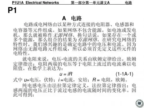
电路
di uL dt
(1-1A-2)
式中 di/dt = 电流变化率, 安培/秒; L = 感应系数, 享利。 电容两端建立的电压正比于电容两极板上积累的电荷q 。 因为电荷的积累可表示为电荷增量dq的和或积分,因此得到 的等式为 : 1 (1-1A-3) u dq
(由于s 是复变量,亟待和零点可能是复数,KZ(s)/P(s) 是复变函数,
因此可用一个有幅值和与其相关的角度或叫幅角的矢量来表示。在公式(23A-2)右边的每一个分解因子可被看作)
P2U4A The Frequency Response Methods: Bode Plots
第二部分第四单元课文A 频率响应法:波特图
P1U5B Closed-loop Control of DC Drivers
第一部分第五单元课文B 直流传动的闭环控制
自动化专业英语课文PART2 Control Theory Unit3 B The Frequency Response Methods Nyquist Diagrams B0703
PART2 Control TheoryUNIT3The Frequency Response Methods:Nyquist DiagramsIntroductionThere are times when it is necessary or advantageous to work in the frequency domain rather than in the Laplace domain of the root locus.For system analysis, the root locus method requires a transfer function,which may be difficult or even impossible to obtain for certain components,subsystems.In many of these cases,the frequency response can be determined experimentally for sinusoidal test inputs of known frequency and amplitude.The nature of the input also influences the choice of techniques to be used for system analysis and design.Many command inputs merely instruct asystem, to move from one steady-state condition to a second steady-state condition.This type of input can be described adequately by suitable steps in position,velocity,and acceleration,and the Laplace domain is appropriate for this purpose.If,however,the interval between such step inputs is decreased so that the system never has time to reach the corresponding steady state,the step representation and Laplace domain are no longer adequate.Such rapidly varying command inputs (or disturbance) may be periodic (adj.周期性的),random (adj.随机性的),or a combination thereof.The wind loading of a tracking radar antenna,for example,results from a mean velocity component that varies with plus superimposed random gusts. If the frequency distribution of these inputs can be calculated, measured, or even estimated, the frequency response can be used to determine their effects upon the system output. The frequency response is a steady-state response .Although some information can be obtained about the transient response, it is only approximate and is subject to misinterpretation(n.曲解,误议).The Frequency Transfer FunctionIt is necessary to develop (v.导出,引入) an input-output relationship that can be used in the frequency domain, i.e., a frequency transfer function. Consider a linear system with a known transfer function G(s) and apply the sinusoidal inputr (t)=0γsin 0ωt or R(s)=02200ωγω+swhere 0γ is the amplitude and 0ω the input or forcing frequency (强制频率) .The transformed output is C(s)=G(s)02200ωγω+sThe partial fraction expansion (部分分式展开式)of C(s) yieldsC(s)=01ωj s C - +02ωj s C ++13γ+s C +243γ+s C +…Where -1γ,-2γ, … are the roots of the characteristic equation of the transfer function.The inverse transform isc(t)=t j e C 01ω+ t j e C 02ω-+t r e C 13-+t r e C 24-+...where the first two terms represent an undamped oscillation resulting from the sinusoidal input, and the transient response. If the system is stable, the transient response will disappear with time, leaving as the steady-state responset j ss e C c 01ω=+t j e C 02ω-The coefficients 1C and 2C are evaluated by the Heaviside expansion theorem asj j G s s G j s C j s 2)(])()([0002200010γωωγωωω=+-=+=; jj G s s G j s C j s 2)(])()([0020200020γωωγωωω--=+-=-= With these values for 1C and 2C ,Eq.(2-3B-1) becomest j t j ss e j G jr e j G j c 00)(2)(20000ωωωωγ---= Since they are complex functions,φωωj e j G G j G j G )(Im Re )(00=+=;φωωj e j G G j G j G -=-=-)(Im Re )(00Where the angle φ is the argument of )(0ωj G and is equal to arctg(ImG/ReG).Eq.(2-3B-2) can now be written as)2()(0000je e j G r c tj t j ss ωωω--= Since the bracketed (v.加括号) terms are equal to )sin(0φω+t ,the steady-state response can be written as)sin()(000φωω+=t c j c ss where 000)(r j G c ω=From these equations we see that sinusoidal input to a linear stable system produces a steady-state response that is also sinusoidal, having the same frequency as the inputbut displaced through a phase angle Φ and having an amplitude that may be different. This steady-state sinusoidal response is called the frequency response of the system. Since the phase angle is the angle associated with the complex function )(0ωj G and the amplitude ratio (c 0/r 0) is the magnitude of )(0ωj G , knowledge of )(0ωj G specifies the steady-state input-output relationship in the frequency domain. )(0ωj G is called the frequency transfer function and can be obtained from the transfer function G(s) by replacing the Laplace variable s by j ω0 . Consequently, if )(0ωj G can be determined from experimental data, G(s) can also be found by replacing j ω0 by s.For a given system, the frequency response is completely specified if the amplitude ratio and phase angle are known for the rage of input frequencies from 0 to +∞ radians per unit time. Consider the stable first-order system of Fig. 2-3B-1 with a transfer function G(s) =1/(τs+1), the frequency transfer function is )1/(1)(+=ωτωj j G , where ω can be arbitrary(n.任意的) frequency. The amplitude ratio is1)(1)()(200+===ωτωωj G r c j M and the phase angle is ωτωτωωφcot )1(1)()(-=+∠-∠=∠=j j G jAs input frequency ω is increased from 0to +∞, we can draw the plot of M and φ, and a polar plot (极坐标图) that traces the tip (n.顶端) of the vector representing the frequency transfer function. Polar plots and M and φ versus (prep …对...) ω plots are used to represent different types of complex functions in the frequency domain. Notice that the constant term in each factor is set equal to unity when working in the frequency domain for convenience, whereas in the Laplace domain the coefficient of the highest power of s is set equal to unity.The Nyquist Stability CriterionIn the frequency domain, the theory of residues (余数定理) can be used to detect any roots in the right half of a plane. As with the root locus method, the characteristic function in the form 1+ KZ(s)/P(s) is used, where again the function KZ (s)/P(s) may or may not be the open-loop transfer function. To develop the Nyquist criterion , the characteristic function itself is written as a ratio of polynomials so that D(s)=1+0)...)(()...)((')()()()()(2121=++++=+=p s p s r s r s K s P s KZ s P s P s Z K Comparing the identities (n.一致性,等式)of Eq.(2-3A-2), we see that 1r -,2r -,…are the rootsof the characteristic equation and that 1p -,2p -,…are the poles of both the characteristic function and KZ(s)/P(s).Poles and roots at the origin have been omitted (v.省略)in the interests of simplicity (n.简单). In many cases, however, it is difficult to factor the denominator polynomial of lose-loop transfer function D(s) to find the location of poles in the s-plane.To prove stability for D(s), it is necessary and sufficient to show that no zeros (for the closed-loop transfer function is poles) i r - are inside the right half of the s-plane. We introduce the Nyquist contour (n.轮廓,外形) D shown in Fig.2-3B-2, which encloses (v.围绕) the entire right half of the s-plane. D consists of the imaginary axis from ∞-j to ∞+j and a semicircle (n.半圆形)of radius (n.半径) R ∞→. In principle, stability analysis is based on plotting[1+KZ(s)/P(s)] in a complex plane as s travels once clockwise around the closed contour D. The factors (s+i r ) and (s+i p ) are vectors from i r - and i p - to s, and for any value of s the magnitude and phase of [1+KZ(s)/P(s)] can be determined graphically by measuring the vector lengths and angles in Fig.2-3B-2, if the i r were known.Note that on the imaginary axis ωj s =. The plot of [1+KZ(s)/P(s)] for s traveling up the imaginary axis from +=0ω to ∞→ω is effect just the polar plot of the frequency response function [1+KZ(ωj )/P(ωj )]. Hence frequency response function indicated in Fig.2-3B-3 by measurement from the pole-zero pattern.Fig.2-3B-2 shows that if s moves once clockwise around D, vectors (s+i r ) and (s+i p ) rotate 360。
自动化专业英语全文翻译
《自动化专业英语教程》-王宏文主编-全文翻译PART 1Electrical and Electronic Engineering BasicsUNIT 1A Electrical Networks ————————————3B Three-phase CircuitsUNIT 2A The Operational Amplifier ———————————5B TransistorsUNIT 3A Logical Variables and Flip-flop ——————————8B Binary Number SystemUNIT 4A Power Semiconductor Devices ——————————11B Power Electronic ConvertersUNIT 5A Types of DC Motors —————————————15B Closed-loop Control of DC DriversUNIT 6A AC Machines ———————————————19B Induction Motor DriveUNIT 7A Electric Power System ————————————22B Power System AutomationPART 2Control TheoryUNIT 1A The World of Control ————————————27B The Transfer Function and the Laplace Transformation —————29 UNIT 2A Stability and the Time Response —————————30B Steady State—————————————————31 UNIT 3A The Root Locus —————————————32B The Frequency Response Methods: Nyquist Diagrams —————33 UNIT 4A The Frequency Response Methods: Bode Piots —————34B Nonlinear Control System 37UNIT 5 A Introduction to Modern Control Theory 38B State Equations 40UNIT 6 A Controllability, Observability, and StabilityB Optimum Control SystemsUNIT 7 A Conventional and Intelligent ControlB Artificial Neural NetworkPART 3 Computer Control TechnologyUNIT 1 A Computer Structure and Function 42B Fundamentals of Computer and Networks 43UNIT 2 A Interfaces to External Signals and Devices 44B The Applications of Computers 46UNIT 3 A PLC OverviewB PACs for Industrial Control, the Future of ControlUNIT 4 A Fundamentals of Single-chip Microcomputer 49B Understanding DSP and Its UsesUNIT 5 A A First Look at Embedded SystemsB Embedded Systems DesignPART 4 Process ControlUNIT 1 A A Process Control System 50B Fundamentals of Process Control 52UNIT 2 A Sensors and Transmitters 53B Final Control Elements and ControllersUNIT 3 A P Controllers and PI ControllersB PID Controllers and Other ControllersUNIT 4 A Indicating InstrumentsB Control PanelsPART 5 Control Based on Network and InformationUNIT 1 A Automation Networking Application AreasB Evolution of Control System ArchitectureUNIT 2 A Fundamental Issues in Networked Control SystemsB Stability of NCSs with Network-induced DelayUNIT 3 A Fundamentals of the Database SystemB Virtual Manufacturing—A Growing Trend in AutomationUNIT 4 A Concepts of Computer Integrated ManufacturingB Enterprise Resources Planning and BeyondPART 6 Synthetic Applications of Automatic TechnologyUNIT 1 A Recent Advances and Future Trends in Electrical Machine DriversB System Evolution in Intelligent BuildingsUNIT 2 A Industrial RobotB A General Introduction to Pattern RecognitionUNIT 3 A Renewable EnergyB Electric VehiclesUNIT 1A 电路电路或电网络由以某种方式连接的电阻器、电感器和电容器等元件组成。
自动化专业英语教程(王宏文第2版)-英译汉
A 电路[1] In the case of a resistor, the voltage-current relationship is given by Ohm’s law, which states that the voltage across the resistor is equal to the current through the resistor multiplied by the value of the resistance.就电阻来说,电压—电流的关系由欧姆定律决定。
欧姆定律指出:电阻两端的电压等于电阻上流过的电流乘以电阻值。
[2]It may be that the inductor voltage rather than the current is the variable of interest in the circuit.或许在电路中,人们感兴趣的变量是电感电压而不是电感电流。
B 三相电路[1] Viewed in this light, it will be found that the analysis of three-phase circuits is little more difficult than that of single-phase circuits. 这样看来,三相电路的分析比单相电路的分析难不了多少。
[2] At unity power factor,the power in a single-phase circuit is zero twice each cycle.在功率因数为1时,单相电路里的功率值每个周波有两次为零。
[3] It should be noted that if the polarity of point A with respect to N ( ) is assumed for the positive half-cycle,应该注意,如果把A点相对于N的极性()定为正半周,那么在用于同一相量图中时就应该画得同相反,即相位差为。
自动化专业英语原文和翻译
自动化专业英语原文和翻译Automation in the Manufacturing Industry: An OverviewIntroduction:Automation plays a crucial role in the manufacturing industry, revolutionizing production processes and enhancing efficiency. This article provides an in-depth analysis of the concept of automation in the manufacturing sector, highlighting its benefits, challenges, and future prospects. It also includes a translation of the text into English.Section 1: Definition and Importance of AutomationAutomation refers to the use of technology and machinery to perform tasks with minimal human intervention. In the manufacturing industry, automation is essential for streamlining operations, reducing costs, and improving product quality. It allows companies to achieve higher production rates, increased precision, and improved safety standards.Section 2: Benefits of Automation in Manufacturing2.1 Increased ProductivityAutomation enables manufacturers to produce goods at a faster rate, leading to increased productivity. With the use of advanced robotics and machinery, repetitive tasks can be performed efficiently, allowing workers to focus on more complex and creative aspects of production.2.2 Enhanced Quality ControlAutomated systems ensure consistency and accuracy in manufacturing processes, leading to improved product quality. By minimizing human error, automation reduces defects and variations, resulting in higher customer satisfaction and reduced waste.2.3 Cost ReductionAutomation helps in reducing labor costs by replacing manual work with machines and robots. Although initial investment costs may be high, long-term savings are significant due to increased efficiency and reduced dependence on human labor.2.4 Improved Workplace SafetyAutomation eliminates the need for workers to perform hazardous or physically demanding tasks. Robots and machines can handle tasks that pose risks to human health and safety, thereby reducing workplace accidents and injuries.2.5 Increased FlexibilityAutomated systems can be easily reprogrammed to adapt to changing production requirements. This flexibility allows manufacturers to respond quickly to market demands, introduce new products, and customize production processes.Section 3: Challenges in Implementing Automation3.1 Initial InvestmentImplementing automation requires substantial capital investment for purchasing and integrating machinery, software, and training. Small and medium-sized enterprises (SMEs) may face financial constraints in adopting automation technologies.3.2 Workforce AdaptationAutomation may lead to job displacement, as certain tasks previously performed by humans are now handled by machines. Companies need to provide training and re-skilling opportunities to ensure a smooth transition for their workforce.3.3 Technical ComplexityAutomation systems often involve complex integration of various technologies, such as robotics, artificial intelligence, and data analytics. Companies must have skilled personnel capable of managing and maintaining these systems effectively.Section 4: Future Trends in Automation4.1 Collaborative RobotsCollaborative robots, also known as cobots, are designed to work alongside humans, assisting them in tasks that require precision and strength. These robots can improve productivity and safety by working in close proximity to humans without the need for extensive safety measures.4.2 Internet of Things (IoT) IntegrationThe integration of automation systems with the Internet of Things allows for real-time monitoring and control of manufacturing processes. IoT enables seamless communication between machines, sensors, and data analytics platforms, leading to predictive maintenance and optimized production.4.3 Artificial Intelligence (AI)AI technologies, such as machine learning and computer vision, enable automation systems to learn and adapt to new situations. AI-powered robots can analyze data, make decisions, and perform complex tasks with minimal human intervention, revolutionizing the manufacturing industry.Conclusion:Automation has become an integral part of the manufacturing industry, offering numerous benefits such as increased productivity, enhanced quality control, cost reduction, improved workplace safety, and increased flexibility. While challenges exist, such as initial investment and workforce adaptation, the future of automation looks promising with the emergence of collaborative robots, IoT integration, and artificial intelligence. Embracing automation technologies will undoubtedly pave the way for a more efficient and competitive manufacturing sector.Translation:自动化在制造业中的应用:概述简介:自动化在制造业中扮演着重要的角色,革新了生产过程,提高了效率。
自动化与电子信息专业英语教程(英文版)(ppt 72页)
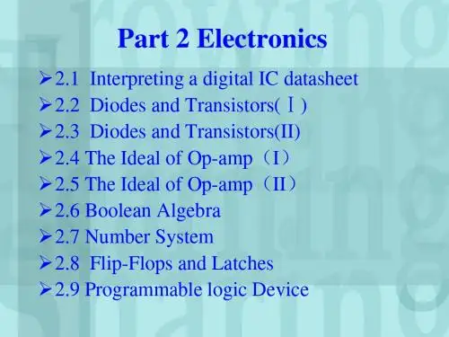
2.1 Interpreting a digital IC datasheet 2.2 Diodes and Transistors(Ⅰ) 2.3 Diodes and Transistors(II) 2.4 The Ideal of Op-amp(I) 2.5 The Ideal of Op-amp(II) 2.6 Boolean Algebra 2.7 Number System 2.8 Flip-Flops and Latches 2.9 Programmable logic Device
negative portion
负半周
full-wave bridge rectifier 全波桥式整流
transformers
变压器
in conjunction with
与…连接
bipolar junction
双极性
proportionality constant 比例常数
base
基极
collector
“in which” 引起 定语从句,修饰 “power supplies”
这是个典型主从复合句。
全句可译为“二极管的一个主要应用是 AC信号 整流,尤其是在某些需要将 AC 电转化为 DC 电的电源中。”
2.3 Diodes and Transistors(II)
2.3.2 Specialized English Words
本句结果较复杂,主句为“Saying that … beyond ” ,“Saying”为动名词作主语,它的宾 语为“that” 引导名词从句。 “means”为主语 “Saying …”的谓语动词,而“that its impedance…”为“means”的宾语从句,而这个从 句又有自己的结果状语“so that…” 。 全句可译为“我们说二极管在 以上导通的电流 无穷大实际上是指它的阻抗变得如此之小导致它 不再是电路中的限制因素。”
自动化专业英语.
crew:(全体工作)人员 (be based on):基于 Intuition:直觉 trail-and-error:试凑法 deal with: 处理 Dynamic response:动态响应 disturbance:干扰 phase:阶段 (Be) concerned with:涉及 determination:决定(策) Plant:工厂,装置,被控对象 parameter:参数 mordification:修正(改) satisfactory:令人满意的 un-,in-,im-,ir-: not Improve:改进(善) performance:性能 Category: 部分 classic: 经(古)典的 Transfer function:传递函数 principally:mainly Laplace: 拉普拉斯 frequency: 频率 Domain:(领)域 advent: 出现 State variable: 状态变量 emphasis:重(要)点 Matrix algebra:矩阵代数 approach: (解决)方法
3
Unit 1 Of Part2 The world of control
control: 控制(器) Regulate:调整(节) Direct:引导,操纵 Command:命令 abound:大量存在 environment:周围,环境 Abstract:抽象 compensate for:弥补,补偿 limitation:限制 Relieve m of n: 将m从n中解放出来 ,使m免于n routine:日常工作 Tedious:乏味的,慢的 power boost:功率助推装置 force:(作用)力 apply:应用,施加 pilot:飞行员 Aerodynamic:空气动力学的 damped Dutch roll mode:阻尼侧倾转向方式 Yaw damper system: 阻尼偏航系统 heading:航线 ,方位 Altitude:(海拔)高度 attitude:(飞行)姿态 freed of:免于 Navigation:导航 4
自动化专业英语王宏文全文翻译
自动化专业英语PART 1 Electrical and Electronic Engineering BasicsUNIT 1 A Electrical Networks ———————————— 3B Three-phase CircuitsUNIT 2 A The Operational Amplifier ——————————— 5B TransistorsUNIT 3 A Logical Variables and Flip-flop —————————— 8B Binary Number SystemUNIT 4 A Power Semiconductor Devices —————————— 11B Power Electronic ConvertersUNIT 5 A Types of DC Motors —————————————15B Closed-loop Control of DC DriversUNIT 6 A AC Machines ———————————————19B Induction Motor DriveUNIT 7 A Electric Power System ————————————22B Power System AutomationPART 2 Control TheoryUNIT 1 A The World of Control ————————————27B The Transfer Function and the Laplace Transformation —————29 UNIT 2 A Stability and the Time Response ————————— 30B Steady State————————————————— 31UNIT 3 A The Root Locus ————————————— 32B The Frequency Response Methods: Nyquist Diagrams ————— 33 UNIT 4 A The Frequency Response Methods: Bode Piots ————— 34B Nonlinear Control System 37UNIT 5 A Introduction to Modern Control Theory 38B State Equations 40UNIT 6 A Controllability, Observability, and StabilityB Optimum Control SystemsUNIT 7 A Conventional and Intelligent ControlB Artificial Neural NetworkPART 3 Computer Control TechnologyUNIT 1 A Computer Structure and Function 42B Fundamentals of Computer and Networks 43UNIT 2 A Interfaces to External Signals and Devices 44B The Applications of Computers 46UNIT 3 A PLC OverviewB PACs for Industrial Control, the Future of ControlUNIT 4 A Fundamentals of Single-chip Microcomputer 49B Understanding DSP and Its UsesUNIT 5 A A First Look at Embedded SystemsB Embedded Systems DesignPART 4 Process ControlUNIT 1 A A Process Control System 50B Fundamentals of Process Control 52UNIT 2 A Sensors and Transmitters 53B Final Control Elements and ControllersUNIT 3 A P Controllers and PI ControllersB PID Controllers and Other ControllersUNIT 4 A Indicating InstrumentsB Control PanelsPART 5 Control Based on Network and InformationUNIT 1 A Automation Networking Application AreasB Evolution of Control System ArchitectureUNIT 2 A Fundamental Issues in Networked Control SystemsB Stability of NCSs with Network-induced DelayUNIT 3 A Fundamentals of the Database SystemB Virtual Manufacturing—A Growing Trend in AutomationUNIT 4 A Concepts of Computer Integrated ManufacturingB Enterprise Resources Planning and BeyondPART 6 Synthetic Applications of Automatic TechnologyUNIT 1 A Recent Advances and Future Trends in Electrical Machine DriversB System Evolution in Intelligent BuildingsUNIT 2 A Industrial RobotB A General Introduction to Pattern RecognitionUNIT 3 A Renewable EnergyB Electric VehiclesUNIT 1A 电路电路或电网络由以某种方式连接的电阻器、电感器和电容器等元件组成。
自动化专业英语教程第二版全文翻译
《自动化专业英语教程》-王宏文-全文翻译PART 1Electrical and Electronic Engineering BasicsUNIT 1A Electrical Networks ————————————3B Three-phase CircuitsUNIT 2A The Operational Amplifier ———————————5B TransistorsUNIT 3A Logical Variables and Flip-flop ——————————8B Binary Number SystemUNIT 4A Power Semiconductor Devices ——————————11B Power Electronic ConvertersUNIT 5A Types of DC Motors —————————————15B Closed-loop Control of DC DriversUNIT 6A AC Machines ———————————————19B Induction Motor DriveUNIT 7A Electric Power System ————————————22B Power System AutomationPART 2Control TheoryUNIT 1A The World of Control ————————————27B The Transfer Function and the Laplace Transformation —————29 UNIT 2A Stability and the Time Response —————————30B Steady State—————————————————31 UNIT 3A The Root Locus —————————————32B The Frequency Response Methods: Nyquist Diagrams —————33 UNIT 4A The Frequency Response Methods: Bode Piots —————34B Nonlinear Control System 37UNIT 5 A Introduction to Modern Control Theory 38B State Equations 40UNIT 6 A Controllability, Observability, and StabilityB Optimum Control SystemsUNIT 7 A Conventional and Intelligent ControlB Artificial Neural NetworkPART 3 Computer Control TechnologyUNIT 1 A Computer Structure and Function 42B Fundamentals of Computer and Networks 43UNIT 2 A Interfaces to External Signals and Devices 44B The Applications of Computers 46UNIT 3 A PLC OverviewB PACs for Industrial Control, the Future of ControlUNIT 4 A Fundamentals of Single-chip Microcomputer 49B Understanding DSP and Its UsesUNIT 5 A A First Look at Embedded SystemsB Embedded Systems DesignPART 4 Process ControlUNIT 1 A A Process Control System 50B Fundamentals of Process Control 52UNIT 2 A Sensors and Transmitters 53B Final Control Elements and ControllersUNIT 3 A P Controllers and PI ControllersB PID Controllers and Other ControllersUNIT 4 A Indicating InstrumentsB Control PanelsPART 5 Control Based on Network and InformationUNIT 1 A Automation Networking Application AreasB Evolution of Control System ArchitectureUNIT 2 A Fundamental Issues in Networked Control SystemsB Stability of NCSs with Network-induced DelayUNIT 3 A Fundamentals of the Database SystemB Virtual Manufacturing—A Growing Trend in AutomationUNIT 4 A Concepts of Computer Integrated ManufacturingB Enterprise Resources Planning and BeyondPART 6 Synthetic Applications of Automatic TechnologyUNIT 1 A Recent Advances and Future Trends in Electrical Machine DriversB System Evolution in Intelligent BuildingsUNIT 2 A Industrial RobotB A General Introduction to Pattern RecognitionUNIT 3 A Renewable EnergyB Electric VehiclesUNIT 1A 电路电路或电网络由以某种方式连接的电阻器、电感器和电容器等元件组成。
自动化专业英语P3U2教学课件
并行输入接口 术语“输入”和“输出”通常指CPU和CPU的输出。如图3-2A-1所示的一个简单接口的标准图。输入接口仅受处理器控制。无论何时处理器寻址输入口,外部数据总线上的数据被允许放到处理器数据总线上,并且当CPU把数据放到总线上时,这一数据是可用的。 在这种接口中,有一个三态缓冲器,它能迫使处理器总线与外部数据线有相同的二进制值。当在不允许状态时,缓冲器输出进入高阻“第三态”,它能从总线上有效地移开数据线,允许其他数据利用系统总线。
P3U2A Interfaces to External Signals and Devices 第三部分第二单元课文A 外部信号与设备的接口
A 外部信号与设备的接口
概述 系统总线上的信号以非常有序的顺序发生。每个信号以事件的特定顺序来启动并在一固定时间后或被另外时间的顺序而终止。在仅有存储器和微处理器的系统中,由微处理器直接启动总线事件。 独立的外部设备和无总线兼容的信号以及与系统总线信号无时态关系的信号都不能直接连到系统总线上。系统总线通信是通过输入/输出接口来完成的。输入/输出接口的主要作用是协调处理器与外部设备之间的数据传输,以及转换为处理器可识别形式的数据。接口的其他作用可提供电隔离、噪声抑制、临时数据存储或数据格式转换。 有几种类型的接口,例如并行输入/输出、数字-模拟转换、模拟-数字转换、实时时钟、直接存储器访问,都是常用的。这里,我们仅限于讨论并行I/O和A/D及D/A。
逐次逼近型A/D 应用在A/D转换器结构上有很广泛的技术。最普通的是逐次逼近型转换器。它具有适度速度和适度分辨率的优点。 它的作用:第一次将输入电压与设为满量程A/D参考电压一半的测试电压相比较。利用标准的D/A转换器来得到测试电压。如果第一次比较后,输入电压大于满量程的一半,那么设定最高有效输出位。如果输入电压小于满量程的一半,那么从测试电压中删掉满量程电压的一半,否则电压保持同一值。 下一次,四分之一的满量程参考电压加到测试电压上,将输入电压与测试电压再一次比较,如果输入电压超过测试电压,那么下一个最高有效位被设定,测试电压,第二位设为0,四分之一满量程参考电压被删除。 这一过程逐次以更小的加权二进制电压重复,直到测试完最低有效位。
- 1、下载文档前请自行甄别文档内容的完整性,平台不提供额外的编辑、内容补充、找答案等附加服务。
- 2、"仅部分预览"的文档,不可在线预览部分如存在完整性等问题,可反馈申请退款(可完整预览的文档不适用该条件!)。
- 3、如文档侵犯您的权益,请联系客服反馈,我们会尽快为您处理(人工客服工作时间:9:00-18:30)。
A 控制的世界简介控制一词的含义一般是调节、指导或者命令。
控制系统大量存在于我们周围。
在最抽象的意义上说,每个物理对象都是一个控制系统。
控制系统被人们用来扩展自己的能力,补偿生理上的限制,或把自己从常规、单调的工作中解脱出来,或者用来节省开支。
例如在现代航空器中,功率助推装置可以把飞行员的力量放大,从而克服巨大的空气阻力推动飞行控制翼面。
飞行员的反应速度太慢,如果不附加阻尼偏航系统,飞行员就无法通过轻微阻尼的侧倾转向方式来驾驶飞机。
自动飞行控制系统把飞行员从保持正确航向、高度和姿态的连续操作任务中解脱出来。
没有了这些常规操作,飞行员可以执行其他的任务,如领航或通讯,这样就减少了所需的机组人员,降低了飞行费用。
在很多情况下,控制系统的设计是基于某种理论,而不是靠直觉或试凑法。
控制系统能够用来处理系统对命令、调节或扰动的动态响应。
控制理论的应用基本上有两个方面:动态响应分析和控制系统设计。
系统分析关注的是命令、扰动和系统参数的变化对被控对象响应的决定作用。
如某动态响应是满足需要的,就不需要第二步了。
如果系统不能满足要求,而且不能改变被控对象,就需要进行系统设计,来选择使动态性能达到要求的控制元件。
控制理论本身分成两个部分:经典和现代。
经典控制理论始于二次大战以传递函数的概念为特征,分析和设计主要在拉普拉斯域和频域内进行。
现代控制理论是随着高速数字计算机的出现而发展起来的。
它以状态变量的概念为特征,重点在于矩阵代数,分析和设计主要在时域。
每种方法都有其优点和缺点,也各有其倡导者和反对者。
与现代控制理论相比,经典方法具有指导性的优点,它把重点很少放在数学技术上,而把更多重点放在物理理解上。
而且在许多设计情况中,经典方法既简单也完全足够用。
在那些更复杂的情况中,经典方法虽不能满足,但它的解可以对应用现代方法起辅助作用,而且可以对设计进行更完整和准确的检查。
由于这些原因,后续的章节将详细地介绍经典控制理论。
控制系统的分类和术语控制系统可根据系统本身或其参量进行分类:开环和闭环系统(如图2-1A-1):开环控制系统是控制行为与输出无关的系统。
而闭环系统,其被控对象的输入在某种程度上依赖于实际的输出。
因为输出以由反馈元件决定的一种函数形式反馈回来,然后被输入减去。
闭环系统通常是指负反馈系统或简称为反馈系统。
连续和离散系统:所有变量都是时间的连续函数的系统称做连续变量或模拟系统,描述的方程是微分方程。
离散变量或数字系统有一个或多个只是在特殊时刻可知的变量,如图2-1A-2b,描述方程是差分方程。
如果时间间隔是可控的,系统被称做数据采样系统。
离散变量随机地产生,例如:为只能接受离散数据的数字计算机提供一个输入。
显然,当采样间隔减小时,离散变量就接近一个连续变量。
不连续的变量,如图2-1A-2c所示,出现在开关或乓-乓控制系统中。
这将分别在后续的章节中讨论。
线性和非线性系统:如果系统所有元件都是线性的,系统就是线性的。
如果任何一个是非线性的,系统就是非线性的。
时变和时不变系统:一个时不变系统或静态系统,其参数不随时间变化。
当提供一个输入时,时不变系统的输出不依赖于时间。
描述系统的微分方程的系数为常数。
如果有一个或多个参数随时间变化,则系统是时变或非静态系统提供输入的时间必须已知,微分方程的系数是随时间而变化的。
集中参数和分散参数系统:集中参数系统是其物理性质被假设集中在一块或多块,从而与任何空间分布无关的系统。
在作用上,物体被假设为刚性的,被作为质点处理;弹簧是没有质量的,电线是没有电阻的,或者对系统质量或电阻进行适当的补偿;温度在各部分是一致的,等等。
在分布参数系统中,要考虑到物理特性的连续空间分布。
物体是有弹性的,弹簧是有分布质量的,电线具有分布电阻,温度在物体各处是不同的。
集中参数系统由常微分方程描述,而分布参数系统由偏微分方程描述。
确定系统和随机系统:一个系统或变量,如果其未来的性能在合理的限度内是可预测和重复的,则这个系统或变量就是确定的。
否则,系统或变量就是随机的。
对随机系统或有随机输入的确定系统的分析是基于概率论基础上的。
单变量和多变量系统:单变量系统被定义为对于一个参考或命令输入只有一个输出的系统,经常被称为单输入单输出(SISO)系统。
多变量(MIMO)系统含有任意多个输入和输出。
控制系统工程设计问题控制系统工程由控制结构的分析和实际组成。
分析是对所存在的系统性能的研究,设计问题是对系统部件的一种选择和安排从而实现特定的任务。
控制系统的设计并不是一个精确或严格确定的过程,而是一系列相关事情的序列,典型的顺序是:1)被控对象的建模;2)系统模型的线性化;3)系统的动态分析;4)系统的非线性仿真;5)控制思想和方法的建立;6)性能指标的选择;7)控制器的设计;8)整个系统的动态分析;9)整个系统的非线性仿真;10)所用硬件的选择;11)开发系统的建立和测试;12)产品模型的设计;13)产品模型的测试。
这个顺序不是固定的,全包括的或必要次序的。
这里给出为后续单元提出和讨论的技术做一个合理的阐述。
B 拉氏变换和传递函数如果图2-1B-1所示的线性系统的输出关系已知,则系统的特性就可以得知。
输入-输出在拉氏域的关系称为传递函数。
由定义,部件或者系统的传递函数是输出的拉氏变换比上输入的拉氏变换。
G(s)=C(s)/R(s)传递函数的定义要求系统是线性的、稳定的、变量是连续的以及初始条件为零。
当系统是集中参数的,没有传输时延或可忽略就显得特别有用。
在以上条件下,传递函数可以表示为两个复拉氏变量多项式之比:110110()()()m m m m n n n n b s b s b N s G s D s a s a s a ----++==+++ 对于实际的系统,由于其积分特性要强于微分特性,所以N(s)的阶次要低于D(s)的阶次。
稍后将表明,在频率域使用的频率传递函数(FTF )可以通过将传递函数里的拉氏变量s 换成j ω而得到。
在方程(2-1B-2)中,分母D(s)称为特征函数是因为其包含了系统的所有物理特性。
将D(s)等于零可以得到特征方程。
特征方程的根决定了系统的稳定性以及对各种输入的响应特性。
分子多项式N(s)是表征输入是如何进入系统的函数。
因此,N(s)不会影响绝对稳定性以及瞬态特性的模式和模式个数。
然而对于某些特殊的输入,N(s)会影响瞬态响应的幅值和符号,因此,正如会影响输出的稳态值一样会影响瞬态响应的形状。
(70页止)拉氏变换拉氏变换来自工程数学,对分析和设计线性系统非常有用。
常系数的常微分方程变换为代数方程可以用于实现传递函数的概念。
而且拉氏域很好运算,传递函数可以很容易运算、修改和分析。
设计人员可以很快就熟练地将拉氏域的变化与时域的行为相联系,而不须求解系统方程。
当需要时域解时,拉氏变换方法也是很直接的。
其解是一个完整的解,包括齐次解(动态解)和特解(稳态解),且初始条件已经自动地包括了。
最后,从拉氏域转换到频率域也很容易。
(拉氏变换第一段止)Unit 2连续或离散系统的稳定性由其对输入或者干扰的响应决定。
直观地说,如果一个系统是稳定的,则其停留在稳态(或者平衡点),除非是受到外部激励,且当外部激励去除后,输出又回到稳态点。
输出经过瞬态阶段后将回到与输入有相同形式的稳态或者是在输入的附近。
如果我们将同样的输入作用于不稳定的系统,其输出将不会回到稳态,而是以无界的方式增长,通常其幅值是指数增长或者振荡增长。
系统的稳定性可以用连续系统的脉冲响应)(t y δ或者离散系统的Kronrcker Δ 响应)(k y δ来定义:一个连续(离散)系统是稳定的,如果其脉冲响应)(t y δ(Kronrcker Δ 响应)(k y δ)当时间趋于无穷大时趋于零。
一个可接受的系统必须至少满足:稳定性、精度和满意的瞬态响应这三个指标。
在陈述:“一个可接受的系统对指定输入和扰动必须有满意的时域响应”已经包含了这三个指标的含义。
因此尽管我们为了方便工作在拉氏域或者频率域,我们必须与时间域(至少是定性的)相联系。
在传递函数所在的方程(2-2A-1)中,系统的阶次定义为特征函数D(s)的阶次,因此D(s)的最高次幂决定了系统的阶次。
第一项为强迫解,对应于输入;第二项为瞬态解,对应于系统的极点。
在图2-2A-2中,该瞬态解为c(t)。
瞬态解看上去为指数衰减的,且通常用于衡量衰减速度的是时间常数:即指数衰减的瞬态解衰减至其初始值的36.8%所需的时间(秒数)。
因为,当t=T,1tT e e --= ,对于一阶惯性环节,时间常数是T 秒。
这也是为什么一阶惯性环节要写成这个形式。
S 的系数立即给出了衰减的速度。
而且,当时间为4T 时, 瞬态解衰减至初始值的1.8%。
B :Steady State控制系统设计就是使装置在有指令信号或者干扰时有满意的行为(时域响应)。
设计者必须清楚地知道整个过程的稳态方程和误差,以及他们对装置的动态性能的影响。
衡量系统的精度之一,就是其如何跟踪给定命令。
这是一项重要的性能指标。
一个导航系统如果不能将飞行器置于合适的轨迹,那么无论有多好的动态性能,都是没有用。
实际系统总是容易受到不希望的输入干扰,例如, 命令输入中的噪声以及由于参数改变在被控对象中产生的干扰或者被控对象工作环境变化产生的干扰。
随着命令输入进入系统的噪声输入需要滤波器进行驱除或者抑制并不对输入信号产生影响。
我们将限于讨论通过被控对象进行系统的噪声而不讨论通过控制器进入系统的噪声。
通常同时将误差的两个部分最小化是困难的。
很明显,具有适当的干扰输入特性的一些知识是很有必要的。
方程2-2B-7的两个误差项都能通过在控制器中加入积分器而消除。
这些附加的积分器增加了系统的型(例如,从1型系统变为2型系统),因此可以消除速度误差,并通过在系统扰动进入点之前引入积分环节,可以消除由输入信号中包含的阶跃扰动引起的稳态误差。
如果要保持系统稳定该附加的积分器必须相应增加至少一个零点。
UNIT 3A :The Root Locus根轨迹技术是当一个单一的参数,例如增益或者时间常数从零到无穷大变化时,确定特征方程的各个根的位置的图形技术。
因此,根轨迹不仅仅提供了系统绝对稳定性的信息,还提供了稳定程度的信息。
稳定程度实际上还是描述动态响应特性的方式。
如果系统是不稳定的或者动态响应不可接受,根轨迹还可以指出可能改进响应的方法而且可以定性描述改进的效果。
零点是使Z(s)为零的s 值,用符号о表示。
不能自动地假设这个零点就是使N(s)为零的闭环传递函数的零点。
它可能是,但不一定。
极点是使P(s)为零的s 值,用符号×表示。
s n 表示n 个极点,其值为零,位于s 平面的原点。
特征方程的根前面已经定义为使D(s)为零的s 值,用符号□表示。
