CY-PJ-A款布线式评价器系统安装说明
大液晶评价器安装使用说明
评价器安装说明一、评价器连接调试。
1.连接评价器正常使用的接口有两个。
在评价器的后面有一个圆形的接口是电源接口,在其旁边的网络接口是正常使用的网口。
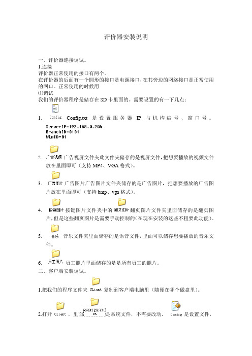
正常使用的时候用⑪调试我们的评价器程序是储存在SD卡里面的。
需要设置的有一下几点:1.Config.txt 是设置服务器IP与机构编号、窗口号。
2.广告视屏文件夹此文件夹储存的是视屏文件,把想要播放的视频文件放在里面即可(支持MP4、VGA格式)。
3.广告图片广告图片文件夹储存的是广告图片,把想要播放的广告图片放在里面即可(支持bmp、vga格式)。
4.按键图片文件夹中的翻页图片文件夹里面储存的是翻页图片,但是这些翻页图片是需要手动控制的(在现在安装的这些不粗要此功能)。
5.音乐文件夹里面储存的是语音文件,里面可以储存想要播放的音乐文件。
6.员工照片里面储存的是是所有员工的照片。
二、客户端安装调试。
1.把我们的程序文件夹复制到客户端电脑里(随便在哪个磁盘里)。
2.打开,里面是系统文件,不需要改动。
是设置文件,其中是设置机构编号与窗口号、服务器IP、对接文件的路径。
其中机构编号与窗口号、服务器IP必须要和相对应的评价器设置一致。
3.然后把发送桌面快捷方式,拖到启动项里面即可。
三、服务器安装调试及统计系统设置。
服务器安装调试1.把我们的程序文件夹复制到客户端电脑里(随便在哪个磁盘里)。
2.打开,里面是设置文件,其中是设置数据库名称和数据库登陆名字及密码。
3.然后把发送桌面快捷方式,拖到启动项里面即可。
统计系统设置1.安装统计系统。
打开文件运行程序,一直点击下一步即可。
安装完成后,双击运行,这样在右下角会出现图标,这样就表示已经运行统计系统了。
然后打开IE浏览器,打开地址http://127.0.0.1,会出现界面。
点击设置,在里面输入正确的数据库名称、数据库登陆用户名及密码,点击保存。
然后返回上一界面,输入账号:admin 密码:123,点击登陆。
会出现下面的界面:1.用户管理①.新增用户-------新增用户,”用户列表”中可以显示出来。
金雀排队评价系统安装使用说明

金雀排队评价系统安装使用说明北京金雀未来科技有限责任公司目录1系统介绍 (4)1.1系统结构拓扑图 (4)1.2系统简介 (5)2硬件安装说明 (6)2.1安装前的工具准备 (6)2.2系统总线及转换器 (7)2.3网络模块压线方式 (7)2.4部件的地址拨码 (9)3软件安装说明 (9)3.1安装数据库 (9)3.2排队管理系统软件安装 (17)4使用说明 (19)4.1系统设置 (19)4.1.1数据库联接设置 (19)4.1.2用户登录 (20)4.1.3角色权限设置 (20)4.1.4用户设置 (21)4.1.5业务设置 (22)4.1.6窗口设置 (23)4.1.7串口设备设置 (25)4.1.8更改用户密码 (27)4.1.9实时察看 (28)4.1.10声音设置 (29)4.1.11多媒体主屏 (31)4.1.12短信设置 (32)4.2排队系统控制中心 (33)4.3发号端 (34)4.3.1发号端界面 (34)4.3.2发号端设置 (37)4.4排队信息统计分析 (45)4.4.1统计表 (45)4.4.2分析表 (46)4.4.3统计图 (47)4.5评价信息统计分析 (48)4.5.1统计表 (49)4.5.2分析表 (49)4.5.3统计图 (50)4.6多媒体主屏控制程序 (51)4.7短信服务程序 (53)4.8网络取号程序 (54)4.9操作器(呼叫器)使用说明 (56)4.9.1键盘按键操作器 (56)4.9.2软件操作器 (57)4.9.3薄膜开关按键操作器 (58)5排队机安装注意事项和常见问题解答 (58)5.1注意事项 (58)5.2常见问题解答 (58)1系统介绍1.1系统结构拓扑图物理呼叫器拓扑图软件呼叫器拓扑图1.2系统简介从硬件设备上分,系统主要部分有:发号机、操作器,也叫物理呼叫器、评价器、LED 显示屏、多媒体主屏等;(发号机本身自带音响系统,如果需要可外接其他音响)注:窗口较少时,可在操作器总线上增加RJ45接口模块,安装评价器;若窗口过多(20个以上),可单独使用一个串口,通过转换器后,引出一条总线接评价器,提高系统运行速度。
usb评价器使用手册-推荐下载

评价管理系统(HPJ)用户手册排队管理系统(PJQ )使用手册一、网络拓扑图:图1.1有排队网络拓扑图图1.2独立评价系统拓扑图排队管理系统(PJQ )使用手册二、呼叫控制器和评价器硬件使用说明:2.1.物理说明型号:HQH05规格尺寸:长133mm×宽84mm×厚25mm电 源:12V DC (数据线集中供电)连 接: RS485插座面 板:11个数字按键,10个功能按键屏 幕:6位LCD 段码液晶显示2.2功能概述:11个数字按键,10个功能按键,具有呼叫、重呼、插号、弃号、转移、暂停、清屏、欢迎、评价、一米线等功能共21键。
2.3功能详细说明:通电后液晶显示如图1,3秒后自动消失,液晶显示界面如图2所示, 000001代表本机地址为01图1图2 待登录界面改地址:在液晶显示地址状态下,输入2008+XX(两位窗口号),如:200805,再按功能键即可修改地址,05代表要更改的新地址。
1)简易登录敲击一次登录/退出键,液晶显示界面如图3;图3 敲击二次登录/退出键,液晶显示界面如图4,1秒钟后液晶显示界面如图5所示;排队管理系统(PJQ)使用手册图5 等待呼叫状态2)工号密码方式登录(服务器程序须启动此登录方式)按两次登录/退出键,呼叫器小液晶屏显示如图5状态,输入4位员工编号,再按一下1/插号键,呼叫器小液晶屏显示如图8,此时再次输入4位员工编号,按一下功能键,再按一下1/插号键,呼叫器小液晶屏显示如图9,此时输入4位的员工登录密码,按一下1/插号键,呼叫器小液晶屏显示如图5,完成登录。
图8图93)退出用户登录后,按下功能键+登陆/退出键退出操作状态,系统等待重新登录,液晶显示界面如图2所示。
此时,服务器收回最新分配的任务,重新分配到其他窗口。
同时窗口屏的LED屏会显示退出工作状态的信息,如“暂停服务”等。
4)呼叫 实现呼叫当前客户的功能。
按呼叫器键盘的呼叫键,则等候大厅音箱发出声音:“叮咚,请XXX号到XX号窗口办理业务”,呼叫器液晶屏显示的右方四位数字为相应客户前来办理的序号。
弱电系统安装调试及验收方法1

秦皇岛市妇幼保健院新建病房综合楼工程建筑智能化系统施工技术要求工程编码:130301S09058-08-01招标人:秦皇岛市社会公益项目建设管理中心(法人章)招标代理机构:河北宏信招标有限公司(法人章)日期:2010年6月9日一、工程概况 (3)二、设计依据 (3)三、智能化系统范围及内容 (4)四、综合布线系统 (4)1、概况 (4)2、技术要求 (5)3、综合布线点表 (9)五、安全防范系统(视频监控、门禁和入侵报警、停车场管理系统) (10)1、概况 (10)2、技术要求 (11)3、视频监控和报警点表 (17)六、楼宇自动化管理系统 (19)1、概况 (19)2、主要子系统 (20)3、工作范围 (23)4、技术要求 (25)5、控制点表 (31)七、手术示范多媒体教学系统 (39)1、概况 (39)2、技术要求 (41)八、有线电视系统 (45)1、概况 (45)2、技术要求 (46)3、电视点表 (47)九、机房系统 (47)1、概况 (47)2、技术要求 (48)✧机房装修工程 (48)✧机房电气系统工程 (51)✧防雷接地 (52)✧综合布线 (60)✧机房环境(视频监控、门禁系统等) (60)一、工程概况本工程为秦皇岛市妇幼保健医院开发建设的新建病房综合楼项目。
该项目建设地点位于秦皇岛市红旗路452号,医院西临红旗路,北靠北环路,东侧为秦皇岛汽车站。
新建病房综合楼位于原有医院南部,在其门诊,病房楼南侧接建。
该项目裙楼部分地下一层,地上四层,主楼部分地下一层,地上十二层,局部十三层,建筑面积为33778平方米,其中地下6012.8平方米,地上27765.5平方米,建筑高度为52.30米。
二、设计依据《智能建筑设计标准》GB/T 50314-2006《智能建筑验收规范》GB 50339-2003《民用建筑电气设计规范》JGJ16-2008《建筑与建筑群综合布线系统工程设计规范》GB/T 50311-2007《建筑与建筑群综合布线系统工程验收规范》GB/T 50312-2007《安全防范系统验收规则》GA 308-2001《安全防范工程技术规范》GB 50348-2004《安全防范工程程序与要求》GA/T 75-94《视频安防监控系统工程设计规范》GB 50395-2007《视频安防监控系统技术要求》GA/T 367-2001《民用闭路监视电视系统工程技术规范》GB 50198-94《入侵报警系统技术要求》GA/T 368-2001《入侵报警工程设计规范》GB 50394-2007《出入口控制系统技术要求》GA/T 394-2002《有线电视系统工程技术规范》GB 50200-1994《分散型控制系统工程设计规定》HG/T 20573-1995《工业自动化仪表工程施工及验收规范》GBJ 93-86《电子信息系统机房设计规范》GB 50174-2008《计算机场站技术通用规范》GB 2887-2000《计算机场地安全要求》GB 9361-88《计算机机房活动地板技术条件》GB 6650-86三、智能化系统范围及内容⏹综合布线系统⏹安全防范系统(视频监控系统和入侵报警系统、门禁系统、停车场管理系统)⏹楼宇自动化管理系统⏹手术示范多媒体教学系统⏹有线电视系统⏹机房系统四、综合布线系统1、概况1.1综合布线系统综合布线系统按照千兆布线标准进行设计。
西维柯 光缆系统 安装及测试指导手册说明书

BrochureCable Subscriber Installation and Test GuideCable Subscriber Installation and Test GuideTesting RF and DOCSIS performanceProblem: A wide range of issues can impact the service quality at the installation, and comprehensive testing is imperative to ensure that any complications are addressed while the technician is on site for installation. Issues include, but are not limited to, new installation craftsmanship, condition or limitations of existing network and components, damage caused in modifications to the home network or in unassociated DIY projects, modem provisioning problems, or other issues in the network that must be referred to maintenance. T esting must be performed at the tap, ground block and CPE locations, and include both RF and service performance verification. Solution: VIAVI offers a variety of the most capable, rugged meters for installation and service testing. The DSP Trilithic Series meters cover the most basic signal level measurement (180 DSP) to DOCSIS 3.1 service testing (DSP 360). The OneExpert series meters (ONX-220 and ONX-620) are the most advanced meters on the market for complete home network installation and service testing, with speed, simplicity, and power. Channel Check and OneCheck test modes provide quick, comprehensive tests in about two minutes, and Session Expert (ONX-620 only) reveals any problems that need attention. A partial list of tests includes RF levels, MER, BER, as well as DOCSIS physical and service performance.Advanced WiFi TestingProblem: 50% of service provider trouble calls are WiFi related. WiFi performance is critically important as final link to customer, who expects the same performance via WiFi as a direct connection. When performanceis degraded, customers begin to think about alternative providers. Poor WiFi performance is very costly due to return visits, and potentially the cost of aost customer.Currently, tech tools for testing are minimal, and typically only test the RF layerwith signal-to-noise and RSSI measurements with one client (probably cellphone). This is inadequate to get a realistic assessment of the user experience.T echnicians have very limited access to the customer home (only when invited)and this opportunity is wasted when WiFi is insufficiently untested. A tech needsto have the ability to test WiFi to verify performance and ensure that therewon’t be trouble around the corner. Customers don’t have to tolerate bad serviceand will go to other providers when multiple service callsare needed.Solution: WiFi testing must be included in the subscriber installation process.The Advanced WiFi option on the ONX-220 allows you to include WiFi as part of the OneCheck test – to certify home WiFi performance as part of a complete verification process. The process is simplified with test capability in the same meter used for installation/service performance testing. Home birth certificate reports are instantly available via StrataSync, with WiFi results included in installation/service test data. The configured OneCheck test can include SpeedCheck, Ookla Speedtest, web connectivity, ping, IP address, WiFi link info, and physical WiFi info. WiFi expert enables the tech to map the home, testing throughout for throughput, airtime, and SNR. Clear results enable customer education for remediation of performance issues, and potential upsell for coverage improvement.Home Leakage Pressure Testing and Ingress MitigationProblem: There are many devices in the home that emit RF signals, including cell phones. Ingress that interferes with services can enter the home coaxial network at any point where the integrity of the grounded shield is broken. Some examples include older devices with poor shielding, bad connectors, loose connections, and damaged cable. Because the source of the ingress and possibly the nature of the leaks are intermittent, the disruption to service can also be intermittent. When technicians don’t have a good, efficient way to test for ingress/leakage repeated service calls are more likely. When ingress occurs, there is potential for disrupted service to multiple customers on the same node. Anywhere there is a leak, there is also a potential for ingress – the leak is like a bi-directional antenna.An ingress scan is often required at installation and service calls to verify that no ingress is coming from the home. The technician connects the meter to the tap or ground block looking back into the home network. If ingress is present, it will be seen in the displayed scan. This assumes that the ingress source signal is active at the time of the test. If it shows that there’s a problem, it doesn’t indicate exactly where in the home network the signal/noise is getting in. The ingress scan is a good test and is especially useful in troubleshooting ingress in the cable plant.A leak detector can be used to look for leaks in the home, but this requires a very sensitive specialized instrument, as the cable signals within the home are at a relatively low level.Solution: RF “pressure tests” of the home network are now used to verify shielding integrity and keep leakage from impacting devices in the home and keep on-air signals from entering the network. For the home network pressure test, high level signals are injected into the drop from the tap, or into the network from the ground block. The signals are at a much higher level than the signals from the cable network (+60 or +40 dBmV) so the leaks from the network will be accentuated. The technician walks through the home with the meter in the leakage mode, and it emits a tone when a leak is detected, and the tone pitch increases as the detected field strength increases. This enables techs to find exact points of failure – a much quicker process than trial-and-error.The Home Leakage T est Kit includes a hand-held Seeker HL Transmitter that generates two frequencies that can be set at two levels. The receiver is the technician’s DSP or OneExpert (ONX) meter with an antenna on the input. This means there is no separate meter required to do this test.Fiber InstallationProblem: Fiber to the home is becoming more common, and withconsolidated workforces, subscriber installation and service isperformed on either coax or fiber. Many are familiar with the need totest the coax side, for performance verification and troubleshooting.T esting fiber is also required, because without testing 20 to 50%of homes don’t pass at first install and/or turnup, resulting in threeadditional tech dispatches in more than 10% of cases.Solution: Fiber testing is simple and saves time as techs get to theroot of problems quickly. A feature of the OneExpert instruments isthe OneCheck Fiber application, which incorporates both inspectionand optical power tests as part of a consistent, repeatable automated installation/service test process. The techis guided through a step-by-step process and test results are collected for analytics to ensure consistent process compliance and enable continuous improvement.Inspect before you connect – the fiber face must be inspected before connecting, to ensure a clean, reliable connection. Dirty connections can cause problems that may be difficult to troubleshoot later. The P5000i simplifies this process with clear pass/fail results. The P5000i connects to VIAVI instruments or a smartphone/ tablet via the USB port. The tech simply cleans the fiber face, and when the inspection passes and continues with assurance that the connection will be reliable.Optical power – checking optical power level is also a quick and easy way to improve first time install success rate. The MP-60 is a broadband power meter which connects via USB, and is suitable for use in single wavelength environments where only a single PON service is being delivered (e.g. a single 1490nm downstream wavelength for G/E-PON) the tech can verify optical power level at the ONT and troubleshoot as needed. Situations where more than one downstream wavelength is present on a fiber (e.g. G/E-PON plus 1550nm RF overlay) will require a dual band or wavelength selective power meter such as the SmartPocket V2 OLP-37XV2 or the Optimeter.Drop Certification and Connection Quality Verification – For PON/FTTH, to ensure successful installation and activation of service on the first visit and to reduce the amount of unnecessary fault escalations, CPE swap outs or drop fiber replacements fiber end face inspection and power level checks must be combined with certification of the fiber drop and verification of the quality of connection to the PON (splitter). The Optimeter provides everything a tech needs in one simple and fast solution. In just 1 minute, with a single fiber connection, and 1 key press, any tech can completely validate and certify a drop fiber. Presenting result on a single view means no need to navigate between different screens and menus. While the fault-finding test feature gives a simple but powerful troubleshooting tool enabling diagnosis of any fiber issue immediately while still on-site in order to determine correct ownership of the repair.Fiber, Ethernet, and WiFi – The Network and Service Companion (NSC-100) can be used to verify optical power level, utilize PON ID information to confirm connection to the correct OL T port, prove the PON network’s service delivery by testing throughput directly from the drop fiber and then validate service delivery within the premises via Ethernet or WiFi (or both) networks in order to troubleshoot and optimize service coverage or set expectations about service performance within the premises.Test Process AutomationProblem: Even with the best test equipment, there are challenges for managing installation and service tests and ensuring that the prescribed processes are being consistently followed. Some difficulties in process management include the need with some test equipment to manually configure each instrument to conform to the process.If the process isn’t automated, the testing is likely to be inconsistent, tests can be complicated, or the test equipment may be out of date or not properly equipped with the test capabilities required. These issues canbe compounded with an inexperienced work force, and the need to communicate and coordinate the resources, resulting in time consuming errors. Without automation, the results data is often inconsistent, with missing or invalid data, and there is a lack of key performance indicators that provide insight into network performance. This difficulty in deployment of consistent procedures (MoPs) leads to a longer work/rework cycle, delayed deployment, unpredictable operational cost, unpredictable staff needs and activation schedules, inability to audit results, and difficulty in addressing problem causes.Solution: StrataSync Timprovement.Benefits:y Job consistency-T-Objective evidence of build, activation and maintenance facilitates rapid close out and paymentbetween operators and contractorsy Simplified process with streamlined training for a flexible workforce:-Pass/Fail tests enable a novice to execute jobs efficiently with reduced repeats-Shift training away from technical expertise needed to determine procedures and interpret resultsy Improve management’s productivity with systems integration:-The VIAVI TPA suite deploys open APIs and mobile apps so that workorders and test results reporting tie instruments into a network provider’s existing dispatch, authorization, and reporting systems -Stop handling paper/email workorders, collating progress reports, and reduce management’sadministrative timey Increase profitability:-Accelerate jobs and time to revenue-Eliminate repeat trips due to undiscovered faults© 2021 VIAVI Solutions Inc. Product specifications and descriptions in this document are subject to change without notice.Patented as described at /patents cablesub-br-cab-nse-ae 30186231 904 1221C ontact Us +1 844 GO VIAVI (+1 844 468 4284)To reach the VIAVI office nearest you, visit /contact VIAVI Solutions。
迅达APMMR现场安装手册

安装缩略图摘要本手册提供了在亚太区范围内使用脚手架安装300P MMR主要安装步骤的详细说明。
本手册为保密文件,并仅供授权的培训人员使用。
目录1 安全建议 (4)概要 (4)使用符号 (4)2 先决条件 (5)产品概述 (5)安装步骤 (7)专用工具 (9)3 施工现场准备工作 (10)4 导轨安装 (15)准备工作 (15)导轨支架安装 (15)导轨安装 (21)导轨基座 (21)导轨安装 (22)连接板校正 (24)5 Varidor 30AP C2 厅门入口安装 (25)门框预安装 (27)地坎支架 (30)门框和机械横梁 (31)地坎和护脚板 (35)门板 (36)C2井道互锁装置 (40)门解锁装置 (41)安装门重锤 (42)防护罩 (44)6 PMS420无齿轮机组安装 (45)机组支架 (47)安装PMS420无齿轮机组 (48)*手动应急操作选配装置 (51)制动器调整和制动力测试 (57)*曳引钢丝绳悬挂装置安装 (58)*安装限速器 (62)7 *安装GGM2-AP对重 (71)先决条件 (71)*机械安装 (72)*缓冲器支撑 (72)*对重校正 (73)*安全钳(选配) (74)*导靴 (76)油杯(选配) (79)*对重块 (79)*补偿链悬挂装置 (80)地震传感器(选配) (81)*调整和最后检查 (82)对重防护屏 (83)*对重防护屏后置 (83)*对重防护屏侧置 (84)8 安装轿厢架FRS9-AP/FRM9-AP (87)安装轿厢架FRS9-AP (87)FRS9-AP安全钳和导靴选配件 (98)FRM9-AP安全钳和导靴选配件 (99)9 安装曳引绳 (100)处理钢丝绳 (100)安装钢丝绳 (101)钢丝绳绳头安装 (105)检查钢丝绳张紧度和绳的润滑 (109)限速器钢丝绳 (110)10 轿厢P9KD-AP(CM)安装 (117)轿厢安装步骤 (118)*安装轿厢装璜 (134)安装满载、超载开关 (143)轿厢平衡装置 (144)11 V30 AP轿门安装 (145)11.1 C2轿门 (145)11.1.1 轿门机驱动 (146)11.1.2 轿门板 (147)11.1.3 轿门刀 (149)安装光幕(MiniMax光幕LVH) (151)12 安装缓冲器 (157)13 安装补偿链 (159)补偿链导向装置 (159)4-滚轮导靴 (159)2-滚轮导靴 (162)补偿链 (165)14 安装MX-GC (170)先决条件 (170)材料范围 (171)控制柜 (172)井道信息 (174)井道信息IGSI (174)绝对值线型井道信息系统 (190)控制柜内模块 (210)机房电缆 (211)井道电缆 (215)准备 (220)安装 (223)调整和最后检查 (229)OKR (231)随行电缆 (236)带IGSI和LONCIB的MX-GC,HQ<=70m (237)带IGSI和LONCIB的MX-GC,HQ>70m (238)带IGSI和LONIC/LONICK的MX-GC,HQ<=70m (239)带IGSI和LONIC/LONICK的MX-GC,HQ>70m (240)控制柜内的概述与名称 (241)15 VARIODYN VF44BR和VF88BR安装 (243)VARIODYN VF44BR安装 (243)VARIODYN VF88BR安装 (249)1 安全建议概要安全要求所有参与的安装人员必须熟悉并遵守公司以及当地的安全规范,特别要注意以下几点:照明必须充足,以保证安全生产。
布线系统的测试与布线工程的验收
布线系统的测试与布线工程的验收来源:ChinaITLab今天已经没有人会 的测试与验收是保障工程质 案例中,也发现这的确是用 的实施对用户来说仍然是个 术介绍可以参考的,在用户 积累的技术知识和经验介绍 说布线工程结束后不需要进行测 量, 保护投资利益的重要环节 户在意识上的进步。
但是我们 太概念化的问题, 很少有涉及 制订测试方案时,这些知识却是 一下,借此来帮助用户完成对自 试了,人们都已经认识到布线系统 。
从我们大量的为用户进行服务的 也看到,有关布线测试和布线工程 布线系统工程的实际验收文章和技 很重要的。
我们在本文中将多年 己布线系统的测试与验收工作。
布线主要涉及的标准与发展布线的测试首先是 要是由于有像千兆以太网这 准的要求加快。
在参考布 洲标准、国际标准、应用标 就会出现差异。
布线的现场 此对这些标准进行逐一的简 与布线的标准紧密相关的。
近几 样的应用需求在推动着布线性能 线的标准时,主要可以从以下几 准。
在对布线系统进行设计和 测试是布线测试的依据, 它与 介,更详细的资料可以直接参考 年来布线的标准发展的很快, 主 的提高,由此导致了对新的布线标 个标准体系来入手:美洲标准、欧 测试时,如果不了解相关的标准, 布线的其它标准息息相关,我们在 标准原件。
1. 美洲标准:成立有八十年历史 Organization for Standar Commission) 主要成员,在 (ANS),而是通过组织有资 制订:的美国国家标准局 ANSI 是 ISOdization) 与 IEC (the Intern国际标准化方面是很重要的角色 质的工作组来推动标准的建立。
(the International ational Electrotechnical 。
ANSI 自己不制订美国国家标准 布线的美洲标准主要由 TIA/EIA①ANSI/TIA/EIA 568-A 到 A5:CommStandard (商业建筑通信布线标准),1 ercial Building Telecommunications Cabling 995/10/25该标准定义了语音与数据通信布线系 为商业布线系统提供了设备和布线产品设 与技术条款, 这些条款可以用于布线系 统,它适用于多个厂家和多种产品的应用环境。
BYCQ140E2P BYCQ140E2PB设计者装饰面板安装指南说明书

INSTALLATION MANUAL BYCQ140E2PBYCQ140E2PB4519102873465234151245354435544+6112352a g b 3a b f d g g 1h 6≤12 mm 21365411264×4×4×c e A AB C CBBYCQ140E2P + BYCQ140E2PBDesigner Decoration panel4P561932-1B 2019.02Installation manual 1The English text is the original instruction. Other languages aretranslations of the original instructions.Before installation ■Leave the unit inside its packaging until you reach the installation site. ■Refer to the installation manual of the indoor unit for items not described in this manual.Preparation before installation For this unit, you are able to select air flow directions. To dischargeair in 2 or 3 directions, it is necessary to purchase the optional blocking pad kit for sealing air discharge outlets.Handling of the decoration panel To prevent any damage to the decoration panel, take care of the following:-Never place the panel facing down.-Never let the panel lean against a wall.-Never put it down on a projecting object.-Never touch or put pressure on the swing flap in order to prevent malfunction of the swing flap.-Be careful not to damage the 4 tabs at the back of the corner decoration cover.Preparing the decoration panel for installation 1Remove the suction grille from the decoration panel.■Unlock the suction grille knobs by pushing them inward (5). ■Open the suction grille (2) while pushing the sliders (6)inward. (See figure 1)■See figure 2. Remove the hooks (2) to detach the suctiongrille from the decoration panel.■Remove all the transporting tapes and 2 brackets fortemporary installation attached on the suction grille.■Attach the brackets for temporary installation on locations (1)if needed. (See figure 2)2Remove the corner decoration cover on each corner by pulling itup in the direction of the arrow. (See figure 3)Installation of the decoration panel to the indoor unitRefer to the installation manual of the indoor unit for details on installing the indoor unit.1Install the decoration panel (See figure 5)BYCQ140E2PBYCQ140E2PB Designer Decoration panel Installation manual ■Read this manual attentively before installation. Donot throw it away. Keep it in your files for futurereference.Improper installation or attachment of equipment oraccessories could result in electric shock, short-circuit, leaks, fire or other damage to the equipment.Be sure only to use accessories made by Daikinwhich are specifically designed for the use with theequipment and have them installed by a professional.If unsure of installation procedures or use, alwayscontact your dealer for advice and information.NOTE To the installerBe sure to instruct the customer how to properlyoperate the system showing him or her theoperation manual of the indoor unit.1Decoration panel 2Suction grille 3Corner decoration cover 4Swing flaps 5Knobs 6Sliders aMounting bracket b Hookc Piping sectiond "Piping side" markinge Drain sectionf "Drain side" markingg Temporary latchh Swing flap motor lead wire 1Hold the decoration panel against the indoor unit by matching thepiping side and drain side marks on the decoration panel with theposition of the piping section and drain section of the indoor unit.2Temporarily install the decoration panel to the indoor unit by hangingthe temporary latch into the hooks of the indoor unit body. (2locations)3Hook the 4 mounting brackets on the corner sections of thedecoration panel onto the hooks around the indoor unit body.Make sure that the swing flap motor lead wire is not caught betweenthe indoor unit and the decoration panel.4Screw all 4 hexagon head screws located in the corner section in forapproximately 5mm. The panel will rise.5Adjust the decoration panel by turning it in the direction indicated bythe arrows on the figure so that the ceiling opening is completelycovered.6See figure 6 (cross section of the air outlet) and tighten the hexagonhead screws until the thickness of the sealing material between thedecoration panel and the indoor unit reduces to 12mm or less.1Indoor unit 2Ceiling 3Sealing material 4Decoration panel 5Swing flap 6Air outletInstallation manual 2BYCQ140E2P + BYCQ140E2PBDesigner Decoration panel4P561932-1B 2019.02Precautions■Improper tightening of the screws (see figure 4) may cause air toleak into the unit and between the ceiling and the decoration panel (1) resulting in formation of contamination (2) and dew (3).■If there is a gap remaining between the ceiling and the decoration panel after tightening the screws, re-adjust the indoor unit body height (see figure 9). Adjustment of the indoor unit body height is possible through the holes in the corners of the decoration panel. The indoor unit must be kept levelled and the drain piping kept unaffected.2Wiring of the decoration panel (See figure 8)■Remove the electric components box lid.Loosen the 2 screws, slide the electric components box lid in the direction of the arrows and disengage it from the hooks.■Securely connect the connectors for swing flap motor lead wire installed on the decoration panel.■Securely fix the swing flap motor lead wire with the supplied clamp.■Replace the electric components box lid reversing the procedure to remove it.Fix gaps between the decoration panel and the ceiling(See figure 10)1If there is any gap between the decoration panel and the ceiling,fix the gap using the fixing holder and screws from the accessories.■Use the screw A to fix the fixing holder C on the panel.■Use the screw B to fix the fixing holder C on the unit. Installation of the suction grille and the corner decoration cover Install the suction grille Install the suction grille by reversing the procedure shown in paragraph "Preparing the decoration panel for installation" on page 1.■Return the suction grille hooks on the decoration panel.■Close the suction grille and lock the suction grille knobs by pushing them outward. ■turning it 90 degrees.■Change the direction when adjusting the direction of the suction grille of multiple units or to comply with demands of the customer.Install the corner decoration cover(See figure 7)1Attach the string of each corner decoration cover to the pin ofthe decoration panel.2Install each corner decoration cover.■First insert the hook at the square tip of the corner decoration cover into the hole at the decoration panel corner. ■Then position the 4 latches of the corner decoration cover tofit into the holes of the decoration panel and gently push the corner decoration cover onto the decoration panel.Make sure to turn off the power supply before wiring!1Swing flap motor lead wire 2Connector 3Electric components box lid 4Hooks 5Screw (2 locations)6ClampNOTE Do NOT over tight screws during assembling pro-cess to avoid any damage.Make sure that the swing flap motor lead wire is notcaught between the indoor unit and the decorationpanel and in between the electric component box lid.NOTE Do NOT use an electric screwdriver to tighten the screws.NOTE Make sure that strings are not hanging out in between the decoration panel and the suction grille.NOTE When the corner decoration cover gets loose during maintenance of the decoration panel of the indoor unit, the string prevents the corner decoration cover from falling on the floor and getting damaged.4P561932-1B 2019.02Co p yri g h t2018Da i k i n。
- 1、下载文档前请自行甄别文档内容的完整性,平台不提供额外的编辑、内容补充、找答案等附加服务。
- 2、"仅部分预览"的文档,不可在线预览部分如存在完整性等问题,可反馈申请退款(可完整预览的文档不适用该条件!)。
- 3、如文档侵犯您的权益,请联系客服反馈,我们会尽快为您处理(人工客服工作时间:9:00-18:30)。
CY-PJ-A款布线式评价器的安装及使用方法
一、硬件的连接方式
有线呼叫器连接方法
首先用一根串口线把转换器连接在电脑主板的串口上,如下图
然后用一头打上水晶头(水晶头的作法标准为TIA/EIA 568B,就是直通线)的网线穿过每个窗口,水晶头插在转换器的网口上,如下图。
在每个窗口穿过的网线上打上两个模块用于呼叫器和评价器的连接。
每个窗口的呼叫器和评价器地址码要一一对应,(如呼叫器地址码为1对应的评价器地址码为129,呼叫器地址码是2对应的评价器地址码为130,以此类推。
)但每个窗口的呼叫器地址码不能重复。
拨码方法下有讲述。
模块的作法:
采用国标B类打线法,即:将8芯网络线选用B类标准颜色一一对应。
例:B 型标准模块线序:
1、橙白
2、橙
3、绿白
4、蓝
5、蓝白
6、绿
7、棕白
8、棕
呼叫器的线序:
8芯线:1、2、4 电源线(12V+)
5、7、8 地(12V-)
3 信号线A
2、 6 信号线B
二、安装服务器
1安装服务器
安装服务器端(只装一台电脑即可,所有数据保存在此电脑上)
打开文件夹服务器端\server\Disk1
双击sever.exe,即可实现服务器的安装。
安装目录保持默认,
然后一直下一步,即可实现服务器的安装。
安装服务器端免注册补丁
打开文件夹服务器端\服务器端免注册补丁\Server
把文件夹里面的内容复制到C:\Program Files\ZdBit\Queue\Server里面替换原来的文件
服务器设置
点击开始-程序-排队系统-系统设置→杂项界面
1杂项里的相关设置
更改为
然后点“应用”,再点“确定
系统设置→员工资料
在左边“添加、删除员工”项里面,可以添加、删除新员工
选中新员工进行编辑,在右边员工资料项里面进行输入员工信息
员工号码→员工工号
员工姓名→工作人员的姓名
所属部门→工作人员的部门
登陆密码→工作人员用于登陆呼叫器的密码
注意:这里的员工信息一定要跟统计评价信息后台网页的职员设置保持一致
关于CY-PJ-A评价器的拨码评价器后面有一个小方框
1=1 2=2 3=4 4=8 5=16 6=32 7=64 8=128
1拨上代表1号
2拨上代表2号
3拨上代表4号
1和2 拨上代表3号
1和3拨上代表5号
1 、
2 、
3 拨上代表6号
依次类推你要多少窗口号,你就拨几上去
注意:后面的8 是一定要拨上去的
三、统计评价信息安装
统计软件最好是安装在服务器电脑上
打开文件夹score_ce
双击
一直点击next即可,安装目录保持默认
然后打开Disk1
双击setup.exe
一直点击next.即可,安装目录保持默认
统计信息设置
1,打开统计软件
开始-程序-启动- web server或者双击C:\web文件夹下的
电脑右下角出现.b的红色图标。
然后打开浏览器,地址栏输入127.0.0.1或本机的IP地址。
进入该页面
登录账号为admin 密码为123 进入
可以在用户管理添加用户、查看用户、给用户分配权限( admin 是超级用户名)
添加用户
查看用户
这里修改用户的权限
打勾的就是为用户分配这个权限不打勾反之
在点开基础设置→机构设置
这里设置你单位的名称
点击总行一栏里的修改
将机构名称修改为你单位的名称,
机构编号不要随意改动
机构编号和排队系统>系统设置> 杂项界面下的
保持一致
把里面的分行1 分行2删除
队列设置这项用不到
窗口设置
根据你们单位自身情况增减窗口注意:窗口编号是从01开始的1-9窗口全部写成01-09 窗口名称→柜台业务名称窗口编号→窗口号所属机构→单位名称
职员设置
这里职员设置也是按照你窗口服务的工作人员的姓名工号来设置的
职员名称→工作人员的姓名职员编号→工作人员的工号所属机构→单位名称
评价设置
点击“好“一栏里的修改
将“好”修改为“满意“,然后点确定时间设置
默认的
数据管理→数据清理
这个就按上面的操作
数据管理→数据备份
这项没什么用处
四、客户端
安装在服务器电脑上
打开文件夹客户端
双击caller.exe安装,一直点击下一步完成呼叫器的安装
3设置呼叫器
点击开始-程序-排队系统-呼叫器
如果出现点击确定就行
点击设置
服务器地址添写服务器端电脑ip
服务器端口,不要变动(重要)
操作器通信端口:软件转换器接入电脑上的com口,默认为com1口
虚拟呼叫器地址码:此处为local (很重要),不需要修改
媒体设置的显示屏COM口改成COM0
其它的不要做改动
设置好了后关闭呼叫器在打开呼叫器,设置才能生效
五、使用方法
打开服务程序,
然后打开
将呼叫器和评价器接到网络模块(连接到软件转换器的呼叫器口)中
用呼叫器进行登录,登录上以后,点击,“开始”评价器即可发生说”欢迎光临”,点击“结束”,评价器即可进行评价“请您对我的服务进行评价”,此时顾客可以进行评价
评价信息查看
打开浏览器,输入127.0.0.1,账号admin,密码123
登录,即可进行评价信息才查询。
注:所有软件都是装在一台电脑上,即服务器电脑,呼叫器的使用是不需要依靠电脑的。