Micro SATA Connector
EC3-1816CLD2NA-中英文说明书-C00-2413-023681
EVOC产品 请注意下列说明:
警告 EVOC产品只允许用于目录和相关技术文件中规定的使用情况。如果要使用其他 公司的产品和组件,必须得到EVOC推荐和允许。正确的运输、储存、组装、装 配、安装、调试、操作和维护是产品安全、正常运行的前提。必须保证允许的环 境条件。必须注意相关文件中的提示。
危险 表示如果不采取相应的小心措施,将会导致死亡或者严重的人身伤害。
警告 表示如果不采取相应的小心措施,可能导致死亡或者严重的人身伤害。
小心 带有警告三角,表示如果不采取相应的小心措施,可能导致轻微的人身伤害。
注意 表示如果不注意相应的提示,可能会出现不希望的结果或状态。
合格的专业人员 本文件所属的产品/系统只允许由符合各项工作要求的合格人员进行操作。
约定 在本文档中,术语“本板”或“产品”有时特指EVOC EC3-1816CLD2NA产品。
说明 安全相关注意事项 为避免财产损失以及出于个人安全方面的原因,请注意本入门指南中关于安 全方面的信息。 文中使用警告三角来指示这些安全信息,警告三角的出现 取决于潜在危险的程度。
目录 1. 产品介绍 .................................................................................................................1
1.1 简介 .................................................................................................... 1
MOLEX-SATA资料

Serial aTa Interconnect Solutions For Storage ApplicationsCurrent T rends- Solid State Drive - Set-T op Box - Digital audio- automotive – Navigation - Brown Goods - Optical Drives - HDTV Home Theatre- Games – 3D Video Mobile Computing - Notebook PC - Sub-Notebook PC- Media PC- Multimedia Peripherals enterprise Computing - Mid range Servers - Network Storage - raiD Storage - Backplane- internet ServicesDesktop Computing - Hard Disk Drive - Motherboard - Power Supply - adapters - Controller Boards - Data Protection - WorkstationapplicationsSerial aTaSATA Signal ConnectorsSATA Connectors for HDD/SSD Slimline SATA Connectors for ODD SATA Power Connectors External SATA ConnectorsCombo SATA Cable Assembliesas a leading supplier of one of the largest growing family of Serial aTa interconnect solutions, Molex continues to be at the forefront of helping storage makers stay competitive with2Serial aTa• S taggered contact length (First-Mate-Last-Break)• G uide pocket for plug and guide post for receptacle • D ifferent orientation with multi footprint • S older tab • S mall form factor• V arious types of housing material (High Temperature/Colours/FeatureReceptacle7 pin plugPlug3Benefit•A llows sequential mating of pins for hot-plugging of hard disk drive • Allows blind-mating• Provides proper matching with different PCB alignment• PCB retention during and after soldering• Improves airflow and thermal-dynamics in an enclosed environment • Cost effectiveness in wide range of applicationsSaTa Connector Family OverviewReceptacle with latchRight angleSMT SATAplug latch typeSATA plug latch type6SaTa SiGNal reCePTaCleSDescriptionlead-Free Order No.FeaturesPlatingHousing Colourlocking OptionPackaging Mates WithRight Angle SMTSATA Signal Receptacle67489-100XX denotes:1 =Gold Flash; 2 = 30µ" Gold;5 = 15µ" Gold BlackFriction LockT raySATASignal PlugsVertical SMTSATA Signal Receptacle67489-800XRight Angle SMT SATA Signal ReceptacleWith Metal Latch 67489-000X Metal Latch67489-200X Metal Latch & Friction LockVertical SMTSATA Signal ReceptacleWith Metal Latch 67489-900X Metal Latch67489-700XMetal Latch & Friction LockSaTa SiGNal PlUGS NON-laTCH TYPeDescriptionlead-Free Order No.FeaturesPlatingHousing ColourPC T ail lengthPeg T ypePackaging Mates WithStandard Mount Right Angle SMT SATA Signal Plug67490-122XX denotes: 0 = Gold Flash;1 = 30 µ" Gold; 5 = 15 µ" Gold BlackNAFlat Metal PegT ray SATA Signal Cable Assemblies67490-123XX denotes: 0 = Gold Flash;5 = 15 µ" Gold T ape & Reel With Mylar 67490-124X T ube With MylarReverse Mount Right Angle SMT SATA Signal Plug67490-322XX denotes: 0 = Gold Flash; 1 = 30 µ" Gold;5 = 15 µ" Gold T ray67490-323X T ape & ReelVertical Through-HoleSATA Signal Plug (Footprint A)67491-002XX denotes: 0 = Gold Flash; 1 = 30 µ" Gold; 2 = 15 µ" GoldX denotes: 0,1,2 = 2.05mmT ray Vertical Through-Hole SATA Signal Plug (Footprint B)67491-103X 67491-1038Gold Flash 3.00mm67491-103930 µ" Gold 67491-104015 µ" GoldSaTa SiGNal PlUGS laTCH TYPeDescriptionlead-Free Order No.FeaturesPlating/Housing Housing ColourPC T ail lengthPeg T ypePackaging Mates WithRight Angle SMT SATA Signal Plug Latch T ype47080-102030 µ" Gold with Matte TinBlackNAFlat Metal PegT ape & Reel With MylarSATA Signal Cable Assemblies47080-400XX denotes: 1 = Gold Flash;2 = 30 µ" Gold; 5 = 15 µ" GoldVertical Through-Hole SATA Signal Plug Latch T ype47155-4001Gold FlashBlack2.10mmT ray47155-4031Blue 47155-4041NaturalVertical SMT SATA Signal Plug Latch T ype67800-50XYX denotes: 2 = 3.45mm peg; 1 = 3.05mm peg;0 =2.65mm peg; --------------- Y denotes: 1 = Gold Flash; 2 = 30 µ" Gold;5 = 15 µ" Gold Black NAStaggered Round Peg 67800-5004Y ellow 67800-5003Blue47306-50XYBlackT ape & Reel With Mylar47306-20XYT ape & Reel 47306-5201T ape & Reel With MylarVertical Through-Hole SATA Signal PlugLatch T ype (Footprint A)67800-8052Thermoplastic, 30 µ" Gold Natural2.85mmFlat Metal PegT ray67800-8245Thermoplastic, 15 µ" Gold 2.10mm 67800-8041Thermoplastic, Gold Flash2.45mmSerial aTaVertical SMT plug latch type7SaTa SiGNal PlUGS laTCH TYPeDescriptionlead-Free Order No.FeaturesPlating/HousingHousing ColourPC T ail lengthPeg T ypePackaging Mates WithVertical Through-Hole SATA Signal Plug Latch T ype (Footprint A)67800-808X Thermoplastic, X denotes:2 = 30 µ" Gold;5 = 15 µ" Gold Blue3.25mmFlat Metal PegT raySATA Signal Cable Assemblies67800-807X Thermoplastic, X denotes:1 = Gold Flash;2 = 30 µ" Gold; 5 = 15 µ" Gold 2.85mm67800-8235Thermoplastic, 15 µ" Gold2.10mm67800-803X Thermoplastic, X denotes:2 = 30 µ" Gold;5 = 15 µ" Gold2.45mm67800-802X Thermoplastic, X denotes:1 = Gold Flash;5 = 15 µ" Gold Black3.25mm67800-8305Thermoplastic,15 µ" Gold2.10mm67800-800X Thermoplastic, X denotes:1 = Gold Flash;2 = 30 µ" Gold; 5 = 15 µ" Gold 2.45mm67800-812X High T emperature Thermoplastic,X denotes:2 = 30 µ" Gold; 5 = 15 µ" Gold 3.25mm67800-8115High T emperatureThermoplastic, 15 µ" Gold 2.85mm67800-82052.45mmT ape & Reel With Mylar67800-810X High T emperature Thermoplastic,X denotes:1 = Gold Flash;2 = 30 µ" Gold T rayVertical Through-Hole SATA Signal Plug Latch T ype (Footprint B)67800-705X Thermoplastic, X denotes:1 = Gold Flash;2 = 30 µ" Gold;5 = 15 µ" Gold Natural2.85mm67800-704X Thermoplastic, X denotes:2 = 30 µ" Gold;5 = 15 µ" Gold2.45mm67800-7082Thermoplastic, 30 µ" GoldBlue 3.25mm67800-707X Thermoplastic, X denotes:1 = Gold Flash;2 = 30 µ" Gold; 5 = 15 µ" Gold2.85mm67800-703X Thermoplastic, X denotes:1 = Gold Flash;5 = 15 µ" Gold2.45mm 67800-702X Thermoplastic, X denotes:1 = Gold Flash;2 = 30 µ" Gold; 5 = 15 µ" GoldBlack 3.25mm67800-701X Thermoplastic, X denotes:1 = Gold Flash;5 = 15 µ" Gold 2.85mm67800-700X Thermoplastic, X denotes:1 = Gold Flash;2 = 30 µ" Gold; 5 = 15 µ" Gold 2.45mm67800-711X High T emperature Thermoplastic,X denotes:1 = Gold Flash; 5 = 15 µ" Gold 2.85mm67800-710X High T emperature Thermoplastic,X denotes:2 = 30 µ" Gold; 5 = 15 µ" Gold2.45mmSerial aTaVertical through-hole plug latch typeSaTa riGHT aNGle HOST reCePTaCleS FOr HDD/SSDDescriptionlead-FreeOrder No.FeaturesZ Height(mm)PlatingFork lock Width (mm)Housing Color Packaging Mates WithDrive FormFactorReverse Mount SMT SATA Host Receptacle67492-142X 4.15X denotes: 0 = Gold Flash; 1 = 30 µ" Gold; 2 = 15 µ" Gold2.45BlackT ray SATA Plugs For HDD/SSD2.5"/3.5"67492-132X 3.5067492-112X 1.8067492-922X 4.9967492-122X T ape & Reel67492-143X 4.15T ape & ReelWith Cap67492-144X 2.3367492-1325 3.50Gold Flash 2.4567492-132630 µ" Gold 67492-132715 µ" Gold 67492-1224 4.99Gold Flash 67492-122530 µ" Gold 67492-122615 µ" Gold67492-163X 2.70X denotes: 0 = Gold Flash; 1 = 30 µ" Gold; 2 = 15 µ" Gold2.3067492-173X 1.95White 67492-162X 2.70Black T ape & Reel 67492-172X 1.95White67492-193X 1.80 2.05BlackT ape & Reel With Cap 67492-192X T ape & ReelT op Mount SMT SATA Host Receptacle47018-400X3.40 2.4647018-201X 2.55T ray 47018-200XT op Mount Right Angle SMT Micro SATA Host Receptacle78109-00010.0030 µ" GoldRound Peg T rayMicro SATA Plugs For HDD/SSD1.8"78109-100178109-0012T ape & Reel With Cap78109-101278320-0001 3.80T ray78320-1001Vertical SMT Micro SATA Host Receptacle78492-000XN.A.X denotes: 1 = Gold Flash; 2 = 15 µ" Gold; 3 = 30 µ" GoldDual- shaped PegBlack (LCP)T ape & Reel With KaptonVertical SMT Micro SATA Host Receptacle78500-000130 µ" GoldSaTa VerTiCal HOST reCePTaCleS FOr HDD/SSDDescriptionlead-FreeOrder No.FeaturesHeight(mm)PlatingPeg length (mm)Kapton T ape Packaging Mates WithDrive FormFactorStandard HeightThrough-Hole SATA Host Receptacle87779-10018.1530 µ" Gold3.70No T raySATA Plugs For HDD/SSD2.5"/3.5"Standard Height SMT SATA Host Receptacle87713-100187713-1005 1.0587713-1006Y es T ape & ReelStandard Height Press-Fit SATA Host Receptacle87701-10013.70NoT rayExtended HeightThrough-Hole SATA Host Receptacle87678-100114.15Extended HeightSMT SATA Host Receptacle87781-1001Extended Height Press-Fit SATA Host Receptacle87780-1001Vertical SMT SATA Host Receptacle78011-00118.151.00T ape & Reel With Cap 78011-0111T ray With Cap8Vertical through-hole receptacleSerial aTaReverse mount right angleSMT receptacleTop mount Micro SATASaTa PlUGS FOr HDD/SSDDescription lead-FreeOrder No.FeaturesPlating Packaging Mates With Drive FormFactorStraddle Mount SATA Plug With Latching 78448-000130 µ" GoldT ape & ReelSATA HostReceptacles 2.5"/3.5" 78448-0011T raySMT SATA Plug Without Jumper 87703-0067Gold FlashT ape & Reel87703-0001T rayRight Angle SMT Micro SATA Plug With Solder T ab 78285-000130 µ" GoldMicro SATAHostReceptacles1.8" 78285-0021T ape & ReelWith Cap78283-0001SaTa TWO PieCe SOlUTiON CONNeCTOrS FOr HDD/SSDDescription lead-FreeOrder No.FeaturesZ Height(mm)PlatingFork lockWidth (mm)Hold-DownT ypePackaging Mates With Drive FormFactorRemovable SATAInterposer(for two piece solution)47657-1X004.80X denotes:0 = Gold Flash;1 = 15 µ" Gold;2 = 30 µ" Gold N.A.Screw T rayWith Cap47657-2X00,SATAPlugs ForHDD/SSD2.5"/3.5"Bottom Mount SMTSATA Header (for two piece solution)47657-2X00 2.10Forklock T ape & ReelWith Cap47657-1X00Removable SATA22 Pins Interposer(for two piece solution)105129-1X004.00N.A.Screw T rayWith Cap105129-2X00,SATAPlugs ForHDD/SSDBottom Mount SMT SATA 22 Pins Header (for two piece solution)105129-2X00 2.10Forklock T ape & ReelWith Cap105129-1X00Removable SATA22 Pins Interposer(for two piece solution)47662-100X8.20N.A.N.A.T rayWith Cap47662-200X,47662-210X,SATAPlugs ForHDD/SSDReverse Mount Through-Hole SATA22 Pins Header (for two piece solution)47662-200X2.10WithForklockT ape & ReelWith Cap47662-100X47662-210X WithoutForklockSATA plugTwo piece SATAMicro SATA plug9Serial aTaSliMliNe SaTa PlUGS FOr ODDDescriptionlead-Free Order No.FeaturesZ-Height (mm)PlatingHold-Down OptionPackaging Mates WithRight Angle SMT Screw Nail T ype47300-100X3.20X denotes:0 or 1 = Gold Flash; 2 or 3 = 15 µ" Gold; 4 or 5 = 30 µ" GoldStainless Steel Screw Nail (X = 0,2,4)ORPhosphor BronzeScrew Nail (X = 1,3,5)T ape & ReelSlimline SATA ReceptaclesRight Angle SMT Soldering Peg T ype47300-102X X denotes: 0 = Gold Flash; 1 = 15 µ" Gold; 2 = 30 µ" GoldSoldering Peg Right Angle SMT Fitting Nail T ype47300-104X Solder NailSliMliNe SaTa reCePTaCleS FOr ODDDescriptionlead-Free Order No.FeaturesZ-Height (mm)PlatingHold-Down OptionPackaging Mates WithVertical SMT With Fitting Nail & Cap47650-0001NAGold FlashSolder T abT ape & ReelSlimlineSATA Plugs47650-000215 µ" GoldRight Angle Through-Hole With Locking Nut & Cap48321-100X1.25X denotes: 0 = Gold Flash; 1 = 15 µ" Gold; 2 = 30 µ" GoldLocking Nut With Pin Alignment48321-200X2.00Locking NutReverse Right Angle Through-Hole With Screw Nail & Cap 48325-400X4.05X denotes: 1 = Gold Flash; 2 = 15 µ" Gold; 3 = 30 µ" GoldScrew Nail48325-500X 9.0548325-600X5.5548325-110X5.00Reverse Right AngleSMT With Forklock & Cap48330-000X 5.10ForklockReverse Right AngleSMT With Forklock & Cap48336-100X5.3548336-200X5.8510Right angle ODD SATA plugRight angle ODD SATA receptacleVertical SMT ODD SATAreceptacleSerial aTaSliMliNe SaTa TWO PieCe SOlUTiON CONNeCTOrS FOr ODDDescription lead-FreeOrder No.FeaturesZ-Height(mm)Plating Hold-Down T ype Packaging Mates WithRemovable SlimlineSATA Interposer(for two piece solution)47628-100X4.65X denotes:2 = Gold Flash;1 = 15 µ" Gold;0 = 30 µ" Gold Screw T rayWith Cap47628-1X12,SlimlineSATA PlugsBottom MountThrough-Hole Slimline SATA Header (for two piece solution)47628-1X12Forklock T ape & ReelWith Cap47628-100X,47639-3X00Removable SlimlineSATA Interposer(for two piece solution)47645-1X015.25Screw T rayWith Cap47645-2X00,SlimlineSATA PlugsVertical Through-Hole Slimline SATA Header (for two piece solution)47645-2X00X denotes:0 = Gold Flash;1 = 15 µ" Gold;2 = 30 µ" GoldForklock T ape & ReelWith Cap47645-1X01Removable SlimlineSATA Interposer (for two piece solution) 47639-1X00 1.82X denotes:5 = Gold Flash;4 = 15 µ" Gold;3 = 30 µ" GoldScrew T rayWith Cap47639-2X10,SlimlineSATA Plugs 47639-3X00 4.00X denotes:0 = Gold Flash;1 = 15 µ" Gold;2 = 30 µ" Gold47628-1X12,SlimlineSATA PlugsRemovable SlimlineSATA Interposer (for two piece solution) 47639-5X10 1.45X denotes:2 = Gold Flash;1 = 15 µ" Gold;0 = 30 µ" Gold47639-2X10,SlimlineSATA PlugsVertical SMT Slimline SATA Header (for two piece solution)47639-2X10 1.82X denotes:0 = Gold Flash;1 = 15 µ" Gold;2 = 30 µ" GoldForklock T ape & ReelWith Cap47639-1X00HeaderInterposer11Serial aTaInterposerSaTa POWer CriMP CONNeCTOrSDescriptionlead-Free Order No.FeaturesPlatingreel Direction Wire Gauge PackagingUse WithSATA Power Crimp T erminal67581-000X X denotes: 0 = Gold Flash; 1 = 30 µ" Gold; 2 = 15 µ" GoldClockwise18 AWGReel SATA Power Crimp Housings67581-001X Anti-Clockwise47128-100X 18 AWG 22 AWG47128-1009UnplatedSlimline SATA Power Crimp T erminal47634-100XX denotes: 0 = Gold Flash; 1 = 30 µ" Gold; 2 = 15 µ" Gold 18-20 AWG 22-24 AWGSlimline SATA Power Crimp HousingsDescriptionlead-Free Order No.FeaturesPitchHousingPackagingUse WithMates WithSATA Power Crimp Housing67582-0000 1.27mmThermoplastic Bag67581 and 47128 SATA Power Crimp T erminalsSATA PlugsSlimline SATA PowerCrimp Housing47634-2000 1.00mm47634-100X Slimline SATA Power Crimp T erminalsSlimline SATA PlugsSaTa POWer iDT CONNeCTOrSDescriptionlead-Free Order No.FeaturesPlatingWire GaugePackagingremarks Mates With/Use WithSATA Power IDT Receptacle67926-0X0Y Y denotes:1 = Gold Flash;2 = 30 µ" Gold;5 = 15 µ" GoldX denotes:0 = 18 AWG;4 = 22 AWGT rayWith Latch Without Bump Mates With SATA Plugs67926-0X2Y With Latch With Bump67926-0X1Y Without Latch With Bump67926-031YY denotes:1 = Gold Flash;5 = 15 µ" Gold20 AWGFeed-T o Cover For SATA Power IDT Receptacle67926-0040 (Non Halogen-Free)NA NA BagFeed-T o T erminationUse With SATA Power IDT ReceptacleFeed-Through Cover For SATA Power IDT Receptacle67926-0841 (Halogen Free) 67926-0041 (Non Halogen-Free)Feed-Through T ermination12Crimp housingIDT feedthrough coverSerial aTaeXTerNal SaTa riGHT aNGle reCePTaCleSDescriptionlead-Free Order No.FeaturesPlatingHousing ColorPeg T ypePackaging Mates WithT op Mount Through-Hole eSATA & USB Combo Receptacle+3.60 mm Contact Height 47661-100X X denotes: 0 = Gold Flash; 1 = 15 µ" Gold; 2 = 30 µ" GoldBlackLinear PegsT ape & Reel With MylarExternal SATA PlugsReverse Mount Through-Hole eSATA & USB Combo Receptacle+0.39 mm Contact Height47403-300X (Halogen Free)With Solder Clips47403-600XReverse Mount Through-Hole USB Receptacle +0.39 mm Contact Height47403-610X Reverse Mount Through-Hole eSATA & USB Combo Receptacle-0.45 mm Contact Height 47403-620XBottom Mount Through-Hole eSATA & USB Combo Receptacle+1.59 mm Contact Height 47403-800XWith Solder T absT ape & Reel Reverse Mount Through-Hole eSATA & USB Combo Receptacle+0.39 mm Contact Height47403-900230 µ" Gold With Solder ClipsT op Mount SMT eSATA Receptacle+2.63 mm Contact Height47379-X000X denotes: 0 = Gold Flash; 1 = 15 µ" Gold; 2 = 30 µ" GoldStaggered PegsT ape & Reel With Mylar47379-X01047379-X100Linear Pegs47379-X110Bottom Mount SMT eSATA Receptacle+3.48 mm Contact Height47391-X000Staggered PegsThrough-Hole eSATA Receptacle+2.63 mm Contact Height47392-0X01X denotes:0 and 5 = Gold Flash; 1 and 4 = 15 µ" Gold; 2 and 3 = 30 µ" Gold; 0, 1, 2 for Wave Solder Only; 3, 4, 5 For IR &Wave Solder47392-1X01Linear Pegs 47392-0X02NaturalStaggered Pegs 47392-1X02Linear Pegs 47392-0X03BlueStaggered Pegs 47392-1X03Linear Pegs 47392-0X04RedStaggered Pegs 47392-1X04Linear Pegs 47392-0X05OrangeStaggered Pegs 47392-1X05Linear PegsT op Mount Through-Hole eSATA & USB Combo Receptacle+2.11 mm Contact Height 78560-000XX denotes: 1 = 30 µ" Gold; 2 = 15 µ" GoldBlack With Solder ClipsT ape & Reel With KaptonT op Mount Through-Hole eSATA & USB Combo Receptacle+1.81 mm Contact Height78561-000X13Serial aTaTop mountcombo receptacleReverse mount combo receptacle14Serial aTaeXTerNal SaTa riGHT aNGle reCePTaCleSDescription lead-Free Order No.FeaturesPlatingHousing ColorPeg T ypePackaging Mates WithBottom Mount Through-Hole Stacked eSATA & USB ComboReceptacle & USB Receptacle +6.38 mm/-3.51 mm Contact Height 105119-X000X denotes: 1 = 15 µ" Gold; 2 = 30 µ" GoldBlackN.A.T ape & Reel With MylarExternal SATA PlugsT op Mount Through-Hole eSATA & USB Combo Receptacle+1.50 mm Contact Height105123-100X X denotes: 0 = Gold Flash; 1 = 15 µ" Gold; 2 = 30 µ" GoldWith Solder T abs T ape & ReelT op Mount Through-Hole eSATA & USB Combo Receptacle+1.64 mm Contact Height 105124-100X With Solder ClipsT ape & Reel With MylarT op Mount Through-Hole eSATA & USB Combo Receptacle+4.18 mm Contact Height 105125-100X Linear PegsBottom Mount Through-Hole eSATA & USB Combo Receptacle-1.99 mm Contact Height 105127-100XWith Solder ClipsReverse Mount Through-Hole eSATA & USB Combo Receptacle-0.45 mm Contact Height 105130-100XReverse Mount Through-Hole eSATA & USB Combo Receptacle+0.40 mm Contact Height 105131-100X With Solder T absBottom Mount Through-Hole eSATA & USB Combo Receptacle+0.31 mm Contact Height 105131-200X With Solder ClipsT ape & ReelT op Mount Through-Hole eSATA & USB Combo Receptacle+3.37 mm Contact Height 105132-100X T ape & Reel With MylarReverse Mount Through-Hole eSATA & USB Combo With Detect Pin Receptacle-0.45 mm Contact Height105161-100X T ape & Reel105161-200XT ape & Reel With MylarCOMBO SaTa CaBle aSSeMBlieSDescriptionOrder No.FeaturesCombo SATA Cable Assembly,Right Angle Male With Latch-T o-Right Angle Female68761-0586Cable length made to customer requirementCombo SATA T o Signal & 4-pin Power Cable Assembly68761-0183Combo SATA Cable Assembly, Straight With Latch-T o-Right Angle68761-0430Combo SATA With Power T o Right Angle Signal With Latch & Micro SATA Cable Assembly68761-0464Combo SATA T o Straight Signal With Latch & Power Cable Assembly68761-0505Combo SATA T o Signal & 4-pin Micro-Fit Cable Assembly68761-024815Serial aTaCaBle aSSeMBlieSDescription Order No.Features Mates With eSATA-T o-eSATA Cable Assembly68782-0001 1.0m, Black eSATA Connectors68782-00022.0m, BlackSlimline SATA Power Cable Assembly68801-19770.26m, BlackSlimline SATA ConnectorsSignal Cable Assembly,Straight-T o-Straight 88750-53100.5m, Grey Contact Plating:0.76µm/30µ" GoldSignal Plugs Combo Plugs 88750-53180.5m, Red 6749067491784488770388750-5418 1.0m, Red Signal Cable Assembly,Straight Latching-T o-Straight Latching 68561-00140.5m, Red 67800470807844868561-0015 1.0m, Red Signal Cable Assembly,Straight-T o-Right Angle 88762-54000.5m, Red 6749067491784488770388762-5410 1.0m, Red Signal Cable Assembly,Straight Latching-T o-Right Angle Latching68561-00160.5m, Red 67800470807844868561-0017 1.0m, RedPower Adapter, Crimping T ype88751-13106", Gold flash, (5V+12V)NA784488770388751-13116", 0.76µm/30µ" Gold, (5V+12V)4-pin Power Harness T o Pigtail, Crimping T ype88751-1410 1.5m, Gold Flash, (5V+12V)88751-1411 1.5m, 0.76µm/30µ" Gold, (5V+12V)5-pin Power Harness T o Pigtail, Crimping T ype88757-7810 1.5m, Gold Flash, (3.3V+5V+12V)88757-7811 1.5m, 0.76µm/30µ" Gold, (3.3V+5V+12V)Power Adapter, IDT T ype88761-45006", Gold Flash, (5V+12V) Feed-T o Version88761-45106", 0.76µm/30µ" Gold, (5V+12V) Feed-T o-VersionPower Adapter, IDT With Latch T ype68561-00186", Gold Flash, (5V+12V) Feed-T o Version7844868561-00196", 0.76µm/30µ" Gold, (5V+12V) Feed-T o-Version4-pin Power Harness T o Pigtail, IDT T ype 88761-4600 1.5m, Gold Flash, (5V+12V) Feed-T o Version784488770388761-4610 1.5m, 0.76µm/30µ" Gold, (5V+12V) Feed-T o-Version4-pin Power HarnessT o Pigtail, IDT With Latch T ype 68561-0020 1.5m, Gold Flash, (5V+12V) Feed-T o Version7844868561-0021 1.5m, 0.76µm/30µ" Gold, (5V+12V) Feed-T o-Version5-pin Power Harness T o Pigtail, IDT T ype 88761-4700 1.5m, Gold Flash,(3.3V+5V+12V) Feed-T o Version784488770388761-4710 1.5m, 0.76µm/30µ" Gold, (3.3V+5V+12V) Feed-T o-Version5-pin Power HarnessT o Pigtail, IDT With Latch T ype68561-0022 1.5m, Gold Flash,(3.3V+5V+12V) Feed-T o Version7844868561-00231.5m, 0.76µm/30µ" Gold, (3.3V+5V+12V) Feed-To-VersionSlimline SATA power cablesSATA power harnessSATA signalcablesSATA poweradapter IDT typeCombo SATA cablesOrder No. 987650-6021 Designed in Singapore/DC/2012.05©2012 Molex。
洁思微观摄像头用户指南:Axiocam 503彩色 黑白微观相机2说明书

User GuideAxiocam 503 color/monoMicroscope CameraCarl Zeiss Microscopy GmbHCarl-Zeiss-Promenade 1007745 Jena, Germany********************/microscopyCarl Zeiss Microscopy GmbHKönigsallee 9-2137081 GöttingenGermanyEffective from: 06 / 2016© Jena 2016 by Carl Zeiss Microscopy GmbH - all rights reservedThis document or any part of it must not be translated, reproduced, or transmitted in any form or by any means, electronic or mechanical, including photocopying, recording, or by any information or retrieval system. Violations will be prosecuted.The use of general descriptive names, registered names, trademarks, etc. in this document does not imply, even in the absence of a specific statement, that such names are exempt from the relevant protective laws and regulations and therefore free for general use. Software programs will fully remain the property of ZEISS. No program, documentation, or subsequent upgrade thereof may be disclosed to any third party, unless prior written consent of ZEISS has been procured to do so, nor may be copied or otherwise duplicated, even for the customer's internal needs, apart from a single back-up copy for safety purposes.ZEISS reserves the right to make modifications to this document without notice.1About this guide 51.1Introduction5 1.2Safety notes conventions6 1.3Text formats and conventions62Safety 82.1Safety Notes8 2.2Limitation of liability9 2.3Warranty93Technical Data 10 3.1Axiocam 503 color/mono103.1.1Binning Mode and Frame Rate133.1.2Live Frame Rates133.1.3Spectral Sensitivity14 4Shipment 15 5Connecting the Camera 165.1Camera Overview16 5.2Building in the interface card17 5.3Mounting the camera on the microsope18 5.4Connecting the camera to the PC18 5.5Connecting the trigger cable19 5.6Function indicator216Installing Software and drivers 22 6.1Installing software and drivers22 7Trouble-shooting 23 7.1Software237.1.1The camera does not appear in the menu of selectablecameras237.1.2You don't see a camera image on your screen237.1.3The color of my image does not correspond to the impressionthrough the ocular23 7.2Hardware247.2.1Vibrations248Maintenance 258.1Optical System25 8.2Cleaning the infrared filter or protective glass259Disposal and Recycling 261 About this guide | 1.1 Introduction1About this guide1.1IntroductionWelcome Welcome to the Axiocam 503 user documentation.The camera is a professional digital camera for universal light microscopy with ahigh resolution 3 Megapixel sensor and a USB 3.0 interface. The camera can beordered as color camera (Axiocam 503 color) or monochrome camera (Axiocam503 mono). As setting up the two camera models is the same, this guide stands forboth camera models.The differences in the specs can be found in the chapter Technical Data [} 10]. Toset up the camera correctly, follow the instructions in this guide step by step.Content1 About this guide | 1.2 Safety notes conventions1.2Safety notes conventionsThe safety notes in this document follow a system of risk levels, defined in thefollowing manner:1.3Text formats and conventionsBold textsBold is used for texts within the software like names of GUI elements (e.g. buttons,sections, tools, menus), buttons on a device, and product names (e.g. MTB 2011).Font type "Courier"Used for programming code, e.g. macro code as well asfor anything that you would type literally whenprogramming, including keywords, data types, constants,method names, variables, class names, and interfacenames.Shortcuts and key commandsShortcuts are written like Crtl+C, meaning you should press Crtl-Key and C-Keysimultaneously.1 About this guide | 1.3 Text formats and conventionsProceduresThe following formats are used for procedures (instructive sequences):Prerequisites¢stands for a condition which must be fulfilled before starting with the action.Procedure1stands for a single step the user is asked to perform.Web-LinksWeb links appear in blue text. To open the linked website, simply click on the link.Please make sure you have an internet connection established before opening theweb link.2 Safety | 2.1 Safety Notes2Safety2.1Safety NotesThe Axiocam 503 has been manufactured and tested by ZEISS according to theregulations specified in CE and has left the manufacturer’s premises in perfectworking order. In order to ensure that this condition is maintained and to avoid anyrisks when operating the system, the user must comply with any notes andwarnings contained in this manual. The manufacturer shall be exempt fromstatutory liability for accidents should the operator fail to observe the safetyregulations.2 Safety | 2.2 Limitation of liability2.2Limitation of liabilityNo warranty shall be assumed by ZEISS during the warranty period if the equipmentis operated without observing the safety regulations. In any such case, ZEISS shallbe exempt from statutory liability for accidents resulting from such operation.2.3WarrantyZEISS shall be exempt from any warranty obligations should the user fail to observethe safety regulations. ZEISS only guarantees the safety, reliability, and performanceof the system if the safety notes are closely observed.3 Technical Data | 3.1 Axiocam 503 color/mono3Technical Data3.1Axiocam 503 color/mono3.1.1Binning Mode and Frame Rate3.1.2Live Frame RatesAxiocam 503 color Max. Ratings at optimum settings; Hardware and color enhancement off:Axiocam 503 mono Max. Ratings at optimum settings3.1.3Spectral SensitivityAxiocam 503 colorFig. 3.1: Axiocam 503 color incl. Hoya C5000 IR Cut FilterAxiocam 503 monoFig. 3.2: Spectral Sensitivity Axiocam 503 mono4 Shipment4ShipmentAccessory (optional)Fig. 4.1: Axiocam trigger cable5 Connecting the Camera | 5.1 Camera Overview5Connecting the Camera5.1Camera OverviewCamera connectionsFig. 5.1: Camera back5 Connecting the Camera | 5.2 Building in the interface card5.2Building in the interface cardThis chapter describes how to build in the PCI express interface card (4 x USB 3.0)into your PC.Prerequisites¢You have read the documentation of the interface card and of your computerbefore you build in the interface card.Procedure1Switch off your PC and all connected peripherals.2Disconnect the PC and the peripherals from the mains and open the computercase.3Examine your PC’s power supply to see if it has Molex type connectors or SATAtype connectors. Choose the appropriate power connector cable for thefollowing steps. If your PC’s power supply has both connector types, chooseonly one cable.4Connect the appropriate power connector cable to one of the openconnectors from your computer’s power supply.5Connect the other end of the power cable to the PCIe interface card.6Insert the PCIe interface card into the appropriate slot on your computer.7Close the computer case and reconnect the peripherals.You can now mount the camera on the microscope and connect it to the PC viathe USB 3.0 interface, see Connecting the camera with PC.5 Connecting the Camera | 5.3 Mounting the camera on the microsope5.3Mounting the camera on the microsopeTo mount the camera onto your microscope’s TV port, use a C-mount adapter. Theadapter is not included in the shipment. You will find some suitbale examples foradapters in the list below:Procedure1Remove the dust cap from the camera’s C-mount port.2Screw the adapter in as far as it will go.3Mount the camera onto the microscope’s TV port. Ensure that no dust entersthe opening of the camera or the microscope’s TV port.5.4Connecting the camera to the PCProcedure1Lay the USB cable (2 in 1) carefully between the camera and the PC.2Connect the USB cables to the USB 3.0 interface card of the PC.3Connect the USB cables with the camera.4If you switch on the PC, the camera will be also switched on.Power is supplied via the USB 3.0 cable. The USB 2.0 cable supplies the peletiercooling. By switching off the PC, the camera will be switched of as well. If thecamera is assembled correctly, the status LED will light red. If you start the software the LED will turn blue. You`ll find a detailed description of the LED status light in the chapter Function indicator5.5Connecting the trigger cableIn this chapter you will learn how to connect the trigger cable (optional) to thecamera and the SVB (signal distribution box).Fig. 5.2: Trigger cableProcedure1Plug the connector Commercial Micro D (7) in the trigger connector on the back of the camera, see Camera Overview [} 16].2Plug the connector Trigger (1) in the socket Trigger Out of the SVB (Signal distribution box).Fig. 5.3: Signal distribution box (SVB) backside3Plug the connector GPO 0 (2) in the socket Trigger In 1 of the SVB (Signal distribution box).4Plug the connector GPO 1 (3) in the socket Trigger In 2 of the SVB.5Connect the connectors GPOPWR (5) and AUXPWR (6) of the trigger cable together.GPO 2 (4) is not connected.5 Connecting the Camera | 5.6 Function indicator5.6Function indicator6 Installing Software and drivers | 6.1 Installing software and drivers6Installing Software and drivers6.1Installing software and driversPrerequisites¢To acquire images with the Axiocam 503 on a PC, you must install ZEISSsoftware (e.g. ZEN or AxioVision). You will find the software installation on theDVD delivered. The camera drivers will be installed automatically during theinstallation of the software.¢Before starting the installation of the software and drivers, the camera must beconnected to the PC, see chapter Connecting the camera to a PC.Procedure1Install the software according to the installation guide delivered with thesoftware.2During the installation you will be asked to install the camera drivers. Followthe procedure by confirming the upcoming messages.3Restart your PC after the installation.4You can check in the device manager if the driver installation was successful.You have installed the software and the camera drivers. You can now startacquiring images with your camera using ZEISS software. For more information,please read the software documentation.7Trouble-shooting7.1Software7.1.1The camera does not appear in the menu of selectablecameras¢Make sure that you have connected the camera and installed the software and drivers in accordance to the instructions in this manual.¢Make sure that you installed the software and drivers with administrative rights. Install the driver with administrative rights again if necessary.7.1.2You don't see a camera image on your screen¢Check the light path setting of the microscope.¢Is the status LED on the camera on? If not, check the cable connections between camera and computer.¢Execute a reset of the camera.¢Execute an automatic exposure measurement.¢Check the display adjustments for the live image.¢Check the aperture diaphragm of the microscope.¢Check the position of the beam splitter between the ocular and the TV port.7.1.3The color of my image does not correspond to theimpression through the ocularIn case of color cameras:¢Check white balance and, if necessary, repeat white balance.¢Check the monitor’s color temperature setting. If necessary, reduce this to the lowest value that can be set (usually 5200 K).In case of monochrome cameras:¢Images of monochrome cameras are displayed by using overlay colors to represent the colors of fluorescence dyes on the monitor. If the color isdifferent to the visual impression in the eyepiece, select a different overlaycolor.7.2Hardware7.2.1VibrationsSudden jolt, vibration or moving objects during the acquisition can detract theimage quality. The intensity of light during exposure time can change as well.¢To avoid jolt use damping systems on your microscope.¢Repeat the shot and take care to ensure the conditions remain calm.8 Maintenance | 8.1 Optical System8Maintenance8.1Optical SystemThe internal optical components of the camera should always be protected. If nolens, or TV adapter with optics, is screwed into the camera's C-Mount thread, thecamera's sensor and protective glass must be protected by screwing the protectivecap onto the camera's C-Mount thread.8.2Cleaning the infrared filter or protective glassContamination of the IR filter (for color cameras only) or the protective glass has anadverse effect on the quality of the resulting image (dark points, cloudy structuresin the image). If there is dry dust on the front side of the infrared filter or protectiveglass, you can remove it with a soft brush or with cotton (wool). Use cleaning fluidfor optics/lenses only to clean the IR filter. Do not use tap water to clean the IRfilter.9 Disposal and Recycling9Disposal and RecyclingThis product has been developed, tested and manufactured in accordance with theapplicable environmental provisions and directives of the European Union:¢The product and its accessories comply with EU directives 2002/95/EC (RoHS)and 2002/96/EC (WEEE), insofar as these apply to this product.¢ZEISS has implemented a take-back and recycling process that ensures thatproper recycling is carried out in accordance with the aforementioned EUdirectives.¢Please contact your ZEISS sales/service organization for details relating todisposal and recycling.¢This product must not be disposed of with domestic waste or using municipalwaste disposal services. In the event of resale, the seller must inform the buyerof the need to dispose of the product appropriately.Carl Zeiss Microscopy GmbHCarl-Zeiss-Promenade 1007745 Jena, Germany********************/microscopyCarl Zeiss Microscopy GmbHKönigsallee 9-2137081 GöttingenGermanyZEISS reserves the right to make modifications to this document without notice.© Jena 2016 by Carl Zeiss Microscopy GmbH - all rights reserved。
mSATA 协议

Proposed Serial ATAOrganization Draft InternationalRevision 20September 9, 2009SATA30_TPR_C101_V20Title: mSATA ConnectorThis is an internal working document of the Serial ATA International Organization. As such, this is not a completed standard and has not been approved. The Serial ATA International Organization may modify the contents at any time. This document is made available for review and comment only.Permission is granted to the Promoters, Contributors and Adopters of the Serial ATA International Organization to reproduce this document for the purposes of evolving the technical content for internal use only without further permission provided this notice is included. All other rights are reserved and may be covered by one or more Non Disclosure Agreements including the Serial ATA International Organization participant agreements. Any commercial or for-profit replication or republication is prohibited. Copyright © 2000-2009 Serial ATA International Organization. All rights reserved.This Draft Specification is NOT the final version of the Specification and is subject to change without notice. A modified, final version of this Specification (“Final Specification”) when approved by the Promoters will be made available for download at this Web Site: . THIS DRAFT SPECIFICATION IS PROVIDED “AS IS” WITH NO WARRANTIES WHATSOEVER, INCLUDING ANY WARRANTY OF MERCHANTABILITY, NON-INFRINGEMENT, FITNESS FOR ANY PARTICULAR PURPOSE OR ANY WARRANTY OTHERWISE ARISING OUT OF ANY PROPOSAL, SPECIFICATION, OR SAMPLE. Except for the right to download for internal review, no license, express or implied, by estopple or otherwise, to any intellectual property rights is granted or intended hereunder.THE PROMOTERS DISCLAIM ALL LIABILITY, INCLUDING LIABILITY FOR INFRINGEMENT OF ANY PROPRIETARY RIGHTS, RELATING TO USE OF INFORMATION IN THIS DRAFT SPECIFICATION. THE PROMOTERS DO NOT WARRANT OR REPRESENT THAT SUCH USE WILL NOT INFRINGE SUCH RIGHTS.THIS DOCUMENT IS AN INTERMEDIATE DRAFT FOR COMMENT ONLY AND IS SUBJECT TO CHANGE WITHOUT NOTICE.* Other brands and names are the property of their respective owners.Copyright © 2005-2009 Serial ATA International Organization. All rights reserved.SATA-IO CabCon Chair:Frank ChuHitachi Global Storage Technologies3403 Yerba Buena RoadSan Jose, CA 95135 USATel: (408) 717-5224Email: Frank.Chu@Author InformationAuthor Name Company Email addressJeffrey Hobbet Lenovo jrhobbet@Edward Chang Samsung Ed.chang@Edmund Poh Molex Edmund.Poh@Workgroup Chair InformationaddressName Email Workgroup ChairpersonFrank.Chu@ CabCon FrankChuRevision HistoryRevision Date Comments3 10/09/2008 Initial Proposal to Suppliers4 11/19/2008 Swapped +B and –B signals to correspond better to typical SATA-IOPCBA layouts.5 11/20/2008 Moved pin 1 SATA assignment to Pin 30Moved pin 20 SATA assignment to Pin 326 7/21/2009 Updated references to mSATAUpdate pin assignments to have DA/DSS on pin 49 and PD on pin 517 7/22/2009 Updated pin table to specify “Host” side for Transmitter/Receiver8 8/4/2009 Removed references to PCIe9 8/4/2009 Renamed to TPR_C101 and added compliance point figure10 8/5/2009 Added Vendor Pins pin 45, 30, 3211 8/12/2009 Added two wire interface notes for pins 30 and 32.12 9/2/2009 Editorial clean up13 9/3/2009 Adding Lab Loads and Compliance PointsFigure1Replaced14 9/4/200915 9/4/2009 Adding mSATA connector drawings16 9/7/2009 Editorial changes17 9/8/2009 Editorial changes for Figure 124+2 and Figure 125+2, replaceReceptacle to Plug18 9/8/2009 Editorial changes suggested by Alvin Cox19 9/9/2009 Editorial changes on Figures20 9/9/2009 Editorial changes, adding references to JC11-MO-XXX and JC11 SO-XXXIntroductionThis proposal is intended to define a new electrical pin-out to allow SATA to be delivered across an mSATA interface connector. This will enable the use of SATA protocol in small form-factor applications where the connectors are readily available in the industry. This proposal is being presented by Lenovo on behalf of Lenovo, SanDisk, Samsung, STEC, and Toshiba.1 Internal mSATA ConnectorThis section defines the requirements of an mSATA configuration with a Serial-ATA interface.The definition supports the following capabilities:•Supports Gen1 (1.5 Gbps) and Gen2 (3 Gbps) transfer rates•Support for mSATA•Support of 3.3 V•Support 4 vendor pins•Support 2 vendor pins, for drive or SSD manufacturing usage1.1 Usage modelThe internal mSATA connector is to be used for embedded applications, part of SATA Rev 3 section 5.2.10 Mobile Applications.(Proposed to be added to Table 2 in the SATA Rev 3 spec – Usage Model Descriptions) Characteristic mSATA Use model section number 5.2.10Cable and/or backplane type BPCable lengthCable Electrical PAttenuation at 4.5GHz PHost-side connector (To be defined)Device-side connector (To be defined)Gen 1i 1.5Gbps RGen 1m 1.5Gbps NSGen 2i 3.0Gbps FSGen 2m 3.0Gbps NSGen1x 1.5Gbps NSGen 2x 3.0Gbps NSHot plug support NSFigure 1: Embedded mSATA Application1.1.1 Embedded ApplicationsApplications and compliance points for mSATA devices in the embedded applications are not defined in this specification. The mSATA interface shall comply with Gen1i and Gen2i specifications. The mSATA host and device shall comply with the SATA Rev 3 standard and is equivalent to the Mobile Applications usage model.1.1.1.1.1 mSATA Lab Load:Due to the direct connect application of mSATA connection, two different types of mSATA adaptors are required as laboratory loads. The device shall be mated to a female adaptor and the host shallFigure 124+1 – LL Laboratory Load for mSATA DeviceFigure 124+2 – LL Laboratory Load for mSATA HostThe electrical characteristics of the LL shall be greater than the required performance of the parameter being measured such that the LL effects of the on the parameter under test may be successfully compensated for, or de-embedded, in the measured data.1.1.1.1.2 mSATA Lab Sourced Signal DetailsAs described in Lab Load Details in 1.1.1.1.1, to properly provide a SATA signal into mSATA device, both female and male type mSATA adaptors are required for device and host, respectively as shown in Figure 125+1 and Figure 125+2.Figure 125+1 – LSS Lab-Sourced Signal for mSATA DeviceFigure 125+2 – LSS Lab-Sourced Signal for mSATA HostThe Lab-Sourced signal is a laboratory generated signal which is calibrated into an impedance matched load of 100 Ohms differential and 25 Ohms common mode and then applied to the RX+ and RX- signals of the Receiver Under Test. The load used to calibrate the LSS shall have an individual return loss greater than 20 dB over a bandwidth of 100 MHz to 5.0 GHz, and greater than 10 dB from 5 GHz to 8 GHz. During calibration, the characteristics of the Lab-Sourced signal shall comply with the specifications of Error! Reference source not found.. When this signal is then applied to the Receiver Under Test the Frame Error Rate specifications of Table 29 shall be met.1.1.1.3.1 mSATA Connector Connection DefinitionThe compliance points of mSATA are shown in Figure 134+1 below. The same concepts of compliance point of SATA extends to the mSATA application. The detailed physical pin dimensions are shown in Figure 134+2.Figure 134+1– Mated Connector Pair for mSATAFigure 134+2– mSATA Connector Pin Detail1.2 General descriptionThe internal mSATA connector is designed to enable connection of a new family of small form factor devices to the Serial ATA interface.The signal assignments are outlined in the tables below. The physical dimensions are currently being developed. .1.3 Connector location on mSATA Form Factor, - (Reference, see JC11, SO-XXX)The connector location is defined in the drawing below.Figure 2 Internal mSATA Card connector location1.4 Mating interfaces1.4.1 Device internal mSATA Card embedded type connector, (Reference, see JC11,MO-XXX)Figure 3 defines the interface dimensions for the internal mSATA connector.Figure 3 Device internal mSATA Card type internal connector1.4.2 Internal mSATA pin signal definitionTable 1 defines the signal assignment of the internal mSATA connection. This connection does not support hot plug capability, so there is no connection sequence specified. There are a total of 52 pins.• 5 pins for 3.3V source• 3 pins for 1.5V source•14 pins for GND• 4 pins for transmitter/receiver differential pairs• 1 pin for device activity / disable staggered spin-up• 1 pin for presence detection• 2 pins for Vendor Specific / Manufacturing• 5 pins for Vendor Specific•17 reserved pins (no connect)Table 1 Signal Assignments for mSATA (proposed)Pin # Type DescriptionP1 Reserved NoConnectSource P2 +3.3V 3.3VConnect P3 Reserved NoP4 GND Return Current PathConnect P5 Reserved NoSource P6 +1.5V 1.5VConnect P7 Reserved NoConnect P8 Reserved NoP9 GND Return Current PathConnect P10 Reserved NoConnect P11 Reserved NoConnect P12 Reserved NoConnect P13 Reserved NoConnect P14 Reserved NoP15 GND Return Current PathConnect P16 Reserved NoConnect P17 Reserved NoP18 GND Return Current PathConnect P19 Reserved NoConnect P20 Reserved NoP21 GND Return Current PathConnect P22 Reserved NoP23 +B Host Receiver Differential Signal PairP24 +3.3V 3.3VSource P25 -B Host Receiver Differential Signal PairP26 GND Return Current PathP27 GND Return Current PathP28 +1.5V 1.5VSource P29 GND Return Current PathP30 Two Wire Interface Two Wire Interface Clock3P31 -A Host Transmitter Differential Signal PairP32 Two Wire Interface Two Wire Interface Data3P33 +A Host Transmitter Differential Signal PairP34 GND Return Current PathP35 GND Return Current PathConnect P36 Reserved NoP37 GND Return Current PathConnect P38 Reserved NoSource P39 +3.3V 3.3VP40 GND Return Current PathSource P41 +3.3V 3.3VP42 Reserved NoConnect P43 GND Return Current PathConnect P44 Reserved NoP45 Vendor Vendor Specific / Manufacturing Pin2Connect P46 Reserved NoP47 Vendor Vendor Specific / Manufacturing Pin2Source P48 +1.5V 1.5VP49 DA/DSS Device Activity Signal / Disable Staggered Spin-up P50 GND Return Current PathP51 Presence Detection Shall be pulled to GND by device1Source P52 +3.3V 3.3VNOTE:1. Presence detection pin provided for tamper proof functionality2. No connect on the host side.3. Pins 30 and 32 are intended for use as a two wire interface to read a memory device to determinedevice information (an example of this would be for use as SMB bus pins). These pins are not designed to be active in conjunction with the SATA signal differential pairs.。
连接器专业知识总结(中英文)
音频 和
视频 连接 器
Audio & Video Connector
HDMI连接 器
DVI连接器 Hssdc2连 接器 Sata连接 器 DIN连接器 Display Port连接 器 IEEE1394 连接器 屏蔽数据 链路 LVDS 连接器(LC EDI) RJ11连接 器 RJ14连接 器
HDMI Connector
CONNECTOR 的专业知识
一 连接器的定义 Definition of Connector
A connector is a coupling device that joins electrical terminations to create an electrical circuit. Connectors enable contact between wires, cables, printed circuit boards, and electronic components.
电源 连接 器
电路 连接 器
射频 同轴 连接 器 光纤 连接 器 汽车 连接 器
照明 连接 器
Modular Jacks & Plug
Power Connector
Circular Connector
RF Coax Connector
MRJ21连接 器 RJ22连接 器 RJ25连接 器 RJ45连接 器 圆形电源 电池连接 器和电池 组 背板电源 电源汇流 条连接器 面板和PCB 插座 电源端子 矩形电源 圆形电源 连接器 标准圆形 连接器 电路RJ45 连接器 DIN连接器 射频连接 器
MRJ21 Connector
RJ22 Connector
RJ25 Connector
mini,sata接口规范
竭诚为您提供优质文档/双击可除mini,sata接口规范篇一:浅谈msatamicrosata与mini固态硬盘(简称ssd)在硬盘业界是个新兴的产物,标准2.5寸sata接口的到处可见,包括1.8寸ziF接口的市场上也比比皆是、屡见不鲜。
我作为个人爱好者而言,常规的固态硬盘已不能激起我的个人兴趣,尤其是那些容易让人混淆不清的微型固态硬盘,倒让我在茶余饭后花费了不少时间。
我是一个有了丰收的喜悦大家可以共享的人,今天以瑞耐斯科技的msata、micromsata与minipci-essd的区别为例,将自己对这些微型硬盘的认知和大家分享,不到之处请大家指正。
首先我们先看下什么是msatassd?sata-io(sata国际接口标准组织),在20xx年下半年之际,丢出了一个叫做msata新连接接口,并将持续发展与推动;而这东西,其实就是原先asus、dell、宏基等家电、小笔电上minipci-essd所采用的连接接口。
接下来联想在20xx年度生产开发的新机中,比如w520、t420、k26、y460、y560等一系列机器上,都预留了一个msata接口用来根据客户需求加装ssd进行硬盘升级,已达到整机性能整倍提升的目的。
说到这里,我要给大家看下这个小家伙的外形了,我们以瑞耐斯的产品为例如下:/cn/images/upFile/20xx12603857105.jpgRenice120g30*50mmmsatassd接口:属于minipci-e系列,即便在外行的人,也看的出来它和排线接口的ziF截然不同;频脚:如果你有放大镜的话,可以验证下,它绝对是(8+18)单面,双面的话肯定是52pin的接口了;传输速度:3gbps,很显然它传速的是sata信号;外形尺寸:50×30×5.8毫米;重量不到10g,够精巧吧!顺便说下,读写都在200mb\s以上,够震撼吧!什么是microsatassd太高深的理论知识,我也不多说了,大家如果想了解可到网上勾一下,我们就单刀直入看其造型吧!/cn/images/upFile/20xx12236191785.jpg接口:属于sata系列频脚:7+7+2传输速度:3gbps,很显然它传速的是sata信号外形尺寸:标准的1.8寸重量:20g顺便说下,其读写性能,和瑞耐斯msata接近3、说到minipci-essd可就是一件很有趣的事情了尺寸为30*50mm的minipci-essd,其外形和msata没有任何区别;但尺寸为30*70mm的minipci-essd,其外形就与msata就很容易区分了。
Century世特力转接头中文说明书

【前言】由衷的感谢您购买世特力裸族硬盘座 USB3.0 SATA6G。
在使用本产品前,请仔细阅读本产品的使用说明书。
【安全注意事项】<请务必遵守>・请在使用前详细阅读安全注意事项并正确使用。
・ 请遵守安全注意事项与警告标识,以避免伤害自己或他人的生命财产安全。
■以上依危害程度将错误操作的状况区分为如下几类■ 冒烟,焦臭,异常噪音发生冒烟,焦臭或异常噪音时,请将电源关闭,电源插头分离,至购买商店检查或咨询本公司客户支持中心。
■ 请勿自行拆解或改造本产品自行拆解或改造本产品都有可能引起硬件损坏的危险。
产品的检查或修理请咨询购买商店或本公司客户支持中心。
■ 机器内部进水或掉入异物产品进水或掉入异物时,请速将电源关闭并分离电源插头,送至购买商店检查或联系本公司售后支持中心。
■ 请勿在高温度或有水气的场所使用本产品请勿在洗手间或浴室等温度高,有水气的地方使用本产品,有触电或机器故障,火灾的危险。
■ 请勿将本产品放在容易晃动的场所请勿将本产品放在倾斜,不平稳或易晃动的地方,若产品掉落或倾倒可能会造成设备损坏。
■ 请遵守电压规定请遵守本产品的电压容许规定交流100~240V,超过指定电压负荷会有火灾,触电或故障的危险。
■ 关于电源线,连接线的使用说明请避免在电源线,连接线上放置本产品主机或其他重物,或用钉子固定,否则可能破坏电线内芯,造成内芯露出或断线等引起的设备故障等危险.另外,请勿将设备放置在可能会绊倒人的地方。
■ 打雷时请勿触碰电源插头可能会造成触电或火灾等危险。
■ 手湿的时候请勿触碰本设备请避免在手湿的时候触碰本设备,否则可能造成设备故障。
■ 关于摆放场所的注意事项请勿将本产品摆放在以下场所,否则可能会造成火灾,触电等危险,或造成产品故障。
・请勿将本产品放在靠近厨房,瓦斯炉,火炉等有油烟的地方。
・请勿将本产品放置在浴室,温室,厨房等湿度极高的地方,或是可能淋到雨水的地方。
・请勿将本产品摆放在室温低于5℃,高于40℃的场所。
sata电源及信号接口定义
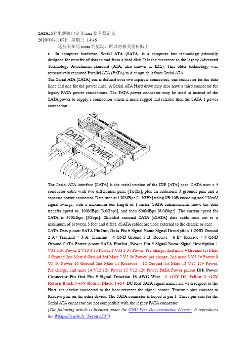
SATA15针电源接口定义/sata信号线定义2010年04月07日星期三14:46这些天在写esata的驱动,所以将相关资料贴上!•In computer hardware, Serial ATA(SATA, is a computer bus technology primarily designed for transfer of data to and from a hard disk. It is the successor to the legacy Advanced Technology Attachment standard (ATA, also known as IDE). This older technology was retroactively renamed Parallel ATA (PA TA) to distinguish it from Serial ATA.The Serial ATA [SATA] bus is defined over two separate connectors, one connector for the data lines and one for the power lines. A Serial ATA Hard drive may also have a third connector for legacy PATA power connections. The PATA power connector may be used in instead of the SATA power to supply a connection which is more rugged and reliable then the SATA-1 power connection.The Serial ATA interface [SATA] is the serial version of the IDE [ATA] spec. SATA uses a 4 conductor cable with two differential pairs [Tx/Rx], plus an additional 3 grounds pins and a separate power connector. Data runs at 150MBps [1.5GHz] using 8B/10B encoding and 250mV signal swings, with a maximum bus length of 1 meter. SATA enhancements move the data transfer speed to; 300MBps [3.0Gbps], and then 600MBps [6.0Gbps]. The current speed for SATA is 300Mbps [3Gbps]. Shielded external SATA [eSATA] data cable runs out to a maximum of between 3 feet and 6 feet. eSATA cables are used external to the chassis or case.SATA Data pinout SATA PinOut, Data Pin #Signal Name Signal Description1 GND Ground 2A+ Transmit + 3A- Transmit - 4GND Ground 5B- Receive - 6B+ Receive + 7GND Ground SATA Power pinout SATA PinOut, Power Pin #Signal Name Signal Description1 V33 3.3v Power 2 V33 3.3v Power 3 V33 3.3v Power, Pre-charge, 2nd mate 4 Ground 1st Mate5 Ground 2nd Mate6 Ground 3rd Mate7 V5 5v Power, pre-charge, 2nd mate8 V5 5v Power 9V5 5v Power 10 Ground 2nd Mate 11 Reserved - 12 Ground 1st Mate 13 V12 12v Power, Pre-charge, 2nd mate 14 V12 12v Power 15 V12 12v Power PATA Power pinout IDE Power Connector Pin Out Pin #Signal Function18 A WG Wire 1 +12V DC Yellow 2 +12V Return Black 3 +5V Return Black 4 +5V DC Red SATA signal names are with respect to the Host, the device connected to the host reverses the signal names. Transmit pins connect to Receive pins on the other device. The SATA connector is keyed at pin 1. These pin outs for the Serial ATA connector are not compatible with the legacy PATA connector.[The following article is licensed under the GNU Free Documentation License. It reproduces the Wikipedia article "Serial ATA"]SATA 1.5 Gb/sFirst-generation Serial ATA interfaces, also known as SATA/150, run at 1.5 Gigahertz (GHz). Serial A TA uses 8B/10B encoding at the physical layer. This encoding scheme has an efficiency of 80%, resulting in an actual data transfer rate of 1.2 Gigabits per second (Gb/s), or 150 megabytes per second (MB/s). The relative simplicity of a serial link and the use of LVDS allow both the use of longer drive cables and an easier transition path to higher speeds.SATA 3.0 Gb/sSoon after SATA's introduction, enhancements were made to the standard. A 3Gb/s signalling rate was added to the PHY layer, offering up to twice the data throughput. To ensure seamless backward compatibility between older SATA and the newer faster SATA/3Gbs devices, the latter devices are required to support the original 1.5Gb/s rate. In practice, some older SATA systems that do not support SATA speed negotiation require the peripheral drive's speed be manually hardlimited to 150Â MB/s with the use of a jumper for a 300Â MB/s drive.Like SATA 1.5Gb/s, SATA 3Gb/s uses 8B/10B encoding resulting in an actual data transfer rate of 2.4 Gb/s, or 300 MB/s.The 3.0Â Gb/s specification has been very widely referred to as “Serial ATA II” (“SATA II”), contrary to the wishes of the Serial ATA standards organization that authored it. The official website notes that SATA II was in fact that organization's name at the time, the SATA 3Gb/s specification being only one of many that the former SATA II defined, and suggests that “SA TA 3Gb/s” be used instead. (The Serial A TA standards organization has since changed names, and is now “The Serial ATA International Organization”, abbreviated SA TA-IO.) SATA-IO plans to further increase the maximum throughput of Serial ATA to 600Â MB/s around the year 2007.SATA 3Gb/s is sometimes also referred to as SATA/300 or SATA II, continuing the line of PATA/100, PATA/133 and SATA/150.SATA 6.0 Gb/sSATA-IO plans to make a 6.0 Gb/s standard. Although the theoretical thoroughput would be doubled, conventional hard disks can't approach saturating this speed. Serial ATA innovationsSATA drops the master/slave shared bus of PATA, giving each device a dedicated cable and dedicated bandwidth. While this requires twice the number of host controllers to support the same number of SATA devices, at the time of SATA's introduction this was no longer a significant drawback. Another controller could be added into a controller ASIC at little cost beyond the addition of the extra seven signal lines and printed circuit board (PCB) space for the cable header.Features allowed for by SATA but not by PA TA include hot-swapping and native command queueing.To ease their transition to SATA, many manufacturers have produced drives which use controllers largely identical to those on their PATA drives and include a bridge chip on the logic board. Bridged drives have a SATA connector, may include either or both kinds of power connectors, and generally perform identically to native drives. They may, however, lack support for some SATA-specific features. As of 2004, all major hard drive manufacturers produce either bridged or native SA TA drives.SATA drives may be plugged into Serial Attached SCSI (SAS) controllers and communicate on the same physical cable as native SAS disks. SAS disks, however, may not be plugged into aSATA controller.Cables and ConnectorsPhysically, the SATA power and data cables are the most noticeable change from Parallel A TA. The SATA standard defines a data cable using seven conductors and 8Â mm wide wafer connectors on each end. SATA cables can be up to 1 m (39 in) long.PATA ribbon cables, in comparison, carry either 40- or 80-conductor wires and are limited to 46 cm (18 in) in length. The reduction in conductors makes SATA connectors and cables much narrower than those of PATA, thus making them more convenient to route within tight spaces and reducing obstructions to air cooling. Unlike early PATA connectors, SATA connectors are keyed — it is not possible to install cable connectors upside down without considerable force.The SATA standard also specifies a power connector sharply differing from the four-pin Molex connector used by PATA drives and many other computer components. Like the data cable, it is wafer-based, but its wider 15-pin shape should prevent confusion between the two. The seemingly large number of pins are used to supply three different voltages if necessary —3.3Â V, 5Â V, and 12Â V. Each voltage is supplied by three pins gangedtogether (and 5 pins for ground). This is because the small pins cannot supply sufficient current for some devices, so they are combined. One pin from each of the three voltages is also used for hotplugging. The same physical connections are used on 3.5-in (90mm) and 2.5-in (70mm) (notebook) hard disks. Some SATA drives include in PA TA style four-pin Molex connector for use with power supplies that lack the SATA power connector. Also, adaptors are available to convert a PATA style power connector to SATA power connector.External SATAeSATA was standardized in mid-2004, with specifically defined cables, connectors, and signal requirements for external SATA drives. eSATA is characterized by:Full SATA speed for external disks (115MB/s have been measured with external RAID enclosures)•No protocol conversion from IDE/SATA to USB/Firewire, all disk features are available to the host•Cable length is restricted to 2m, USB and Firewire span longer distances.•Minimum and maximum transmit voltage decreased to 400mV - 500mV•Minimum and maximum receive voltage decreased to 240mV - 500mVUSB and Firewire require conversion of all communication with the external disk, so external USB/Firewire enclosures include an IDE or SATA bridge chip that translates from the ATA protocol to USB or Firewire. Drive features like S.M.A.R.T. cannot be exploited that way and the achiveable transfer speed with USB/Firewire is only about half of the entire bus data rate of about 50MB/s. This limited effective data transfer rate becomes very visible when using an external RAID array and also with fast single disks which may yield well over 70MB/s during real use.Currently, most PC motherboards do not have an eSA TA connector. eSATA may be enabled through the addition of an eSATA host bus adapter (HBA) or bracket connector for desktop systems or with a Cardbus or ExpressCard for notebooks.Note:Prior to the final specification for eSATA, there were a number of products designed for external connections of SATA drives. Some of these use the internal SATA connector or even connectors designed for other interface specifications, such as IEEE 1394. These products are not eSA TA compliant.eSATA does not provide power, which means that external 2.5" disks which would otherwise be powered over the USB or Firewire cable need a separate power cable when connected over eSATA.eSATA compared to other buseseSA TA PATA Fire Wire 1394b USB 2.0 Actual Speed 2.4 >Gib/s 1064 Mib/s 786 Mib/s ~375 Mib/sMax. cable length 2 meters 46 centimetres4.5 meters 16 cables canbedaisy chained up to 72meters5 metersPower cablerequired?Yes Yes No NoDevices per Channel 1 (5 withmultiplier)3 (3rd deviceread only)63 127Backward compatibilityThe backward compatibility of SATA hard discs is virtually non-existent in the sense that SATA drives will not work with the same connectors that IDE, SCSI, or any other format of hard drive connect to. It is, however, possible to purchase convertors that attach to the rear of the SATA hard disc and will allow it to function as an IDE drive. This can prove useful in situations where one wishes to use their SATA drive on older motherboards that may not have SATA connections, etc.SATA vs SCSISCSI currently offers transfer rates higher than SATA, but is a more complex bus usually resulting in higher costs to the user. Some drive manufacturers offer longer warranties for SCSI devices, however, indicating a possibly higher manufacturing quality control of SCSI devices compared to PATA/SA TA devices.conn_sata.gif(10.79 KB)3030299030-SATA-15P-RA-core-power-connector-dwg.gif(14.14 KB)类别:电脑技术| | 添加到搜藏| 分享到i贴吧| 浏览(1386) | 评论(0)。
- 1、下载文档前请自行甄别文档内容的完整性,平台不提供额外的编辑、内容补充、找答案等附加服务。
- 2、"仅部分预览"的文档,不可在线预览部分如存在完整性等问题,可反馈申请退款(可完整预览的文档不适用该条件!)。
- 3、如文档侵犯您的权益,请联系客服反馈,我们会尽快为您处理(人工客服工作时间:9:00-18:30)。
Micro SATA Connectors Series 78103, 78109, 78285, 78320
Sharon Law Global Product Manager Commercial Products Division (APS)
78103
78109 78285
78320
Development Background
Serial ATA was developed to meet the demand for both faster speed and higher capacity storage drives that keeps on increasing along the digital revolution. With a higher data-transfer rate up to 300MBps, Serial ATA is a natural replacement of the Parallel ATA which could only support data-transfer rate up to 133MBps. The micro SATA connector is designed to enable connection of slim 1.8” drive of form factor 54mm x 78.5mm x (5mm or 8mm) to the Serial ATA interface.
Markets and Applications
Mobile Computing – Notebook PC – Sub-notebook PC Emerging Trends – Set Top Box – Game Console – Solid State Drives
Features and Benefits
Features Benefits Staggered contact lengths (First-Mate-Last-Break) Allows sequential mating of pins for hot-plugging of device drive Guide pocket for plug and guide post for receptacle Power segment key High temperature thermoplastic housing Plastic locating peg for plug Metal locating pin for receptacle Friction locking Solder tab Allows blind-mating Prevents insertion of non-micro SATA power cables Provides lead-free process capability Ensures proper locating on PCB Ensures proper locating on PCB and extra retention to PCB Ensures secure mating of connectors and cable assemblies Provides extra retention to PCB
Comparison between 2.5” / 3.5” SATA and micro (1.8”) SATA
Existing SATA Plug for 2.5”& 3.5”HDD
15 Pins
12V, 5V, 3.3V
Power Segment
Signal Segment
7 Pins
Micro SATA Plug for 1.8” HDD
Power Segment Key
9 Pins
5V, 3.3V
Power Segment
Signal Segment
7 Pins
Additional Features
Guide Post
Locating Pegs Guide Pocket
Solder Tabs
Power Segment Key Metal Locating Pin Staggered Length
Plug Specifications
Reference Information Packaging: Tray UL File No.: Pending CSA File No.: Pending Mates With: Micro SATA Combo Receptacle Designed In: Millimeters Electrical Voltage: 30V Max Current: 1.5A Contact Resistance: 30 milliohms max. Dielectric Withstanding Voltage: 500V AC Insulation Resistance: 1000 Megohms min. 20N (4.50 lb) max. with backplane receptacle 45N (10.11 lb) max. with non latching power & signal cable receptacle Unmating Force: 2.5N (0.56 lb) min. with backplane receptacle 8N (1.8 lb) min. with non latching power cable receptacle 10N (2.25 lb) min. with non latching signal cable receptacle Durability: 50 cycles for internal cable application 500 cycles for backplane application Physical Housing: LCP, Glass Filled, UL 94V-0, Black Contact: Copper Alloy Plating: Contact Area — 0.76µm min. Gold (Au) Solder Tail Area — 0.05µm min. Gold (Au) Underplating — Nickel (Ni) PCB Thickness: 0.35mm Operating Temperature: -40ºC to +105ºC Mechanical Mating Force:
Receptacle Specifications
Reference Information Packaging: TBA UL File No.: Pending CSA File No.: Pending Mates With: Micro SATA Combo Plug Designed In: Millimeters Electrical Voltage: 30V Max Current: 1.5A Contact Resistance: 30 milliohms max. Dielectric Withstanding Voltage: 500V AC Insulation Resistance: 1000 Megohms min. Mechanical Mating Force: Unmating Force: Durability: Physical Housing: Nylon (PA) 9T, Glass Filled, UL 94V-0, Black Contact: Copper Alloy Plating: Contact Area Solder Tail Area Underplating PCB Thickness: Operating Temperature: — 0.76µm min. Gold (Au) —Tin (Sn) —Nickel (Ni) 0.80mm -40ºC to +105ºC 20N (4.50 lb) max. 2.5N (0.56 lb) min. 500 cycles for backplane application.
Micro (1.8”) SATA Connector Pin Layout
Ordering Information
Datum A to PCB sitting surface, 3.80mm,
Top Mount Datum A to PCB sitting plane, 1.15mm, Mid Mount Datum A to PCB sitting plane, 1.29mm Datum A to PCB sitting plane, 3.15mm Mating Z-Height SSD 78285-0001
1.8”HDD 78103-00011.27mm (.050”) Pitch
Micro SATA
Device Plug,
Surface Mount 78320-0001
1.27mm (.050”) Pitch
Micro SATA
Right Angle,
Receptacle,
Surface Mount HDD / SSD Drive Type Drive form factor 78109-0001Order No.Description
Thank You! Questions?。